JP2005271663A - Net body and net body fastener and tire slip prevention device - Google Patents
Net body and net body fastener and tire slip prevention device Download PDFInfo
- Publication number
- JP2005271663A JP2005271663A JP2004085279A JP2004085279A JP2005271663A JP 2005271663 A JP2005271663 A JP 2005271663A JP 2004085279 A JP2004085279 A JP 2004085279A JP 2004085279 A JP2004085279 A JP 2004085279A JP 2005271663 A JP2005271663 A JP 2005271663A
- Authority
- JP
- Japan
- Prior art keywords
- net body
- tightening
- tire
- width direction
- net
- Prior art date
- Legal status (The legal status is an assumption and is not a legal conclusion. Google has not performed a legal analysis and makes no representation as to the accuracy of the status listed.)
- Pending
Links
Images


Landscapes
- Tires In General (AREA)
Abstract
【課題】別体の補助金具を設けることなく緊締索を取り付け可能にしたネット体と、フックを緊締索の端部に設けるようにしたネット体の締結具と、これらネット体および締結具を用いて製造し易いタイヤ滑り止め装置を提供する。
【解決手段】締結具4は、ネット体3の幅方向一方側を緊締する緊締索19a、19bと、接続部材20a、20bとを備えており、ネット体3の幅方向一方側には、緊締索19a、19bを取り付ける取付部16がネット体3と一体に形成されており、この取付部16は、ネット体3の帯長手方向に向いた孔17aを有するループ形状とされていて、この取付部16内に芯材6がループ状に埋設されており、緊締索19a、19bの一端側に、接続部材20a、20bと連結するための連結部22が設けられ、連結部22はフック体23の基部23aを緊締索19a、19bに埋設固定して形成され、緊締索19a、19bが孔17aに挿通されている。
【選択図】図1A net body in which a tightening cord can be attached without providing a separate auxiliary metal fitting, a net body fastener in which a hook is provided at an end of the tightening cord, and the net body and the fastener are used. An anti-slip device for a tire that is easy to manufacture is provided.
A fastener 4 includes fastening lines 19a and 19b for fastening one side of the net body 3 in the width direction, and connecting members 20a and 20b. An attachment portion 16 for attaching the cords 19a and 19b is formed integrally with the net body 3, and this attachment portion 16 has a loop shape having a hole 17a facing the longitudinal direction of the band of the net body 3. The core member 6 is embedded in a loop shape in the portion 16, and a connecting portion 22 for connecting to the connecting members 20 a, 20 b is provided on one end side of the tightening cords 19 a, 19 b, and the connecting portion 22 is a hook body 23. The base portion 23a is embedded and fixed in the tightening cords 19a and 19b, and the tightening cords 19a and 19b are inserted into the holes 17a.
[Selection] Figure 1
Description
本発明は、タイヤ滑り止め用のネット体とこのネット体の締結具およびこれらを用いたタイヤ滑り止め装置に関するものである。 The present invention relates to a net body for preventing tire slip, a fastener for the net body, and a tire slip preventing apparatus using the same.
従来、タイヤ滑り止め装置として、タイヤの外周部に巻回されて幅方向一方側がタイヤ外側に装着されるとともに幅方向の他方側がタイヤ内側に装着される帯状のネット体を備え、緊締索を備えた締結具を用いてネット体の幅方向一方側を締結することでタイヤに装着されるものがある(例えば特許文献1参照)。この従来のタイヤ滑り止め装置のネット体には、締結具を取り付けるためにネット体とは別体の補助金具が複数設けられている。
また、ネット体を締結するための緊締索には、ロープの端部を折り返してカシメ金具でカシメることでループ部を形成し、このループ部にフックが取り付けられたものがある(例えば特許文献2参照)。
In addition, there is a tightening cord for fastening a net body in which a loop portion is formed by folding back an end portion of a rope and caulking with a caulking fitting, and a hook is attached to the loop portion (for example, Patent Documents). 2).
従来のタイヤ滑り止め装置のネット体では、補助金具をネット体に複数取り付けなければならず、その分、ネット体の製造工程が多くて手間がかかっていた。また、従来のネット体の締結に用いる締結具の緊締索は、カシメ金具を用いてループ部を形成していたため、この部分が嵩張ってしまい、緊締索をネット体に取り付ける際に邪魔になる場合があった。
そこで、本発明は、ネット体の幅方向の端部に緊締索を取り付けるための取付部を形成することによって別体の補助金具を設けることなく緊締索を取り付けることができるようにしたネット体を提供することを目的とする。
In the net body of the conventional tire anti-slip device, a plurality of auxiliary metal fittings must be attached to the net body, and accordingly, the manufacturing process of the net body is large, which takes time. In addition, since the conventional tightening cord for fastening the net body has a loop portion formed by using a caulking fitting, this portion becomes bulky and becomes an obstacle when the fastening cord is attached to the net body. There was a case.
Therefore, the present invention provides a net body that can be attached to a tightening cord without providing a separate auxiliary metal fitting by forming an attachment portion for attaching the tightening cord to an end of the net body in the width direction. The purpose is to provide.
本発明の他の目的は、カシメ金具等の取付具を用いることなく、フックを緊締索の端部に設けるようにしたネット体の締結具を提供することである。
また、本発明の他の目的は、ネット体の幅方向の端部に緊締索を取り付けるための取付部を形成することによって補助金具を設けることなく緊締索を取り付けることができるようにしたネット体と、カシメ金具等の取付具を用いることなくフックを緊締索の端部に設けるようにしたネット体の締結具とを組み合わせて、製作が容易なタイヤ滑り止め装置を提供することである。
Another object of the present invention is to provide a net-type fastener in which a hook is provided at an end of a tightening line without using a fitting such as a caulking fitting.
Another object of the present invention is to provide a net body capable of attaching a tightening cord without providing an auxiliary metal fitting by forming an attachment portion for attaching the tightening cord to an end portion in the width direction of the net body. The present invention also provides a tire anti-slip device that is easy to manufacture by combining a net body fastener in which a hook is provided at the end of a tightening line without using a fitting such as a caulking fitting.
本発明は上記の目的を達成するために以下の技術的手段を講じた。
すなわち、第1に、タイヤの外周部に巻回されて、幅方向一方側がタイヤ外側に装着され、幅方向の他方側がタイヤ内側に装着される帯状のネット体において、前記ネット体の幅方向他方側には、ネット体を緊締するための緊締索を取り付ける取付部が前記ネット体と一体に形成されており、この取付部は、ネット体の帯長手方向に向いた孔を有するループ形状とされており、この取付部内に芯材がループ状に埋設されていることである。
これによれば、取付部をネット体に一体に形成することによって、別体の補助金具をネット体に取り付ける必要がなく、製造工程を短縮することができる。
In order to achieve the above object, the present invention takes the following technical means.
That is, first, in the belt-like net body wound around the outer peripheral portion of the tire, one side in the width direction is attached to the tire outer side, and the other side in the width direction is attached to the tire inner side, the other in the width direction of the net body On the side, a mounting portion for attaching a tightening cord for tightening the net body is formed integrally with the net body, and the mounting portion is formed in a loop shape having a hole facing the band longitudinal direction of the net body. The core material is embedded in a loop shape in the mounting portion.
According to this, by forming the attachment portion integrally with the net body, it is not necessary to attach a separate auxiliary metal fitting to the net body, and the manufacturing process can be shortened.
第2に、タイヤの外周部に巻回される帯状のネット体の幅方向一方側を緊締する有端状の緊締索と、緊締索を無端状に接続する接続部材とを備えたネット体の締結具において、前記緊締索の一端側に、前記接続部材と連結するための連結部が設けられ、連結部は先端がフック状のフック体の基部を緊締索に埋設固定して形成されていることである。
これによれば、フック体の基部が緊締索の端部に埋設固定されているので、従来のようにカシメ金具等の取付具を用いずに、フックを緊締索の端部に設けることができ、フックの基部の周りが嵩張ることもなく、邪魔にならない。
Second, a net body comprising an end-like tightening cord that fastens one side in the width direction of a belt-like net body wound around the outer periphery of the tire, and a connection member that connects the tightening cord endlessly. In the fastener, a connecting portion for connecting to the connecting member is provided on one end side of the tightening cord, and the connecting portion is formed by embedding and fixing a base portion of a hook body having a hook shape at the distal end. That is.
According to this, since the base portion of the hook body is embedded and fixed to the end portion of the tightening line, the hook can be provided at the end portion of the tightening line without using a fitting such as a caulking fitting as in the prior art. The area around the base of the hook is not bulky and does not get in the way.
第3に、タイヤの外周部に巻回されて、幅方向一方側がタイヤ外側に装着され、幅方向の他方側がタイヤ内側に装着される帯状のネット体と、ネット体の締結具を備えたタイヤ滑り止め装置において、前記締結具は、ネット体の幅方向一方側を緊締する有端状の緊締索と、緊締索を無端状に接続する接続部材とを備えており、前記ネット体の幅方向他方側には、前記緊締索を取り付ける取付部が前記ネット体と一体に形成されており、この取付部は、ネット体の帯長手方向に向いた孔を有するループ形状とされており、この取付部内に芯材がループ状に埋設されており、前記緊締索の一端側に、前記接続部材と連結するための連結部が設けられ、連結部は先端がフック状のフック体の基部を緊締索に埋設固定して形成され、前記緊締索が前記孔に挿通されていることである。 Thirdly, a tire including a belt-like net body wound around an outer peripheral portion of a tire and attached to the tire outer side on one side in the width direction and attached to the tire inner side on the other side in the width direction, and a fastener for the net body In the anti-slip device, the fastener includes an end-like tightening rope that fastens one side in the width direction of the net body, and a connection member that connects the tightening line endlessly, and the width direction of the net body On the other side, an attachment portion for attaching the tightening cord is formed integrally with the net body, and this attachment portion is formed in a loop shape having a hole facing the band longitudinal direction of the net body. A core material is embedded in a loop shape in the portion, and a connecting portion for connecting to the connecting member is provided on one end side of the tightening cord, and the connecting portion tightens the base portion of the hook body having a hook-like tip. Embedded and fixed, and the tightening cord is It is that they are inserted into.
これによれば、取付部をネット体に一体に形成することによって、別体の補助金具をネット体に取り付ける必要がなく、製造工程を短縮することができるとともに、フック体の基部が緊締索の端部に埋設されているので、カシメ金具等の取付具を用いずに、フックを緊締索の端部に設けることができ、フックの基部の周りが嵩張ることもなく、この部分が邪魔になることもない。
また、緊締索の端部にフック体の基部を埋設しているので、この基部まわりが嵩張ることがなく、取付部の孔に緊締索を挿通するときの邪魔にならず、タイヤ滑り止め装置の組み立て(製造)が容易になる。
According to this, by forming the attachment portion integrally with the net body, there is no need to attach a separate auxiliary metal fitting to the net body, the manufacturing process can be shortened, and the base of the hook body can be tightened. Since it is embedded at the end, the hook can be provided at the end of the tightening cord without using a fitting such as a caulking fitting, and the area around the base of the hook is not bulky. There is nothing.
In addition, since the base of the hook body is embedded at the end of the tightening cord, the circumference of the base does not become bulky, and does not obstruct the insertion of the tightening cord through the hole of the attachment portion. Assembling (manufacturing) becomes easy.
本発明によれば、ネット体は別体の補助金具を設けることなく緊締索を取り付けることができる。
また、ネット体の締結具については、カシメ金具等の取付具を用いることなく、フックを緊締索の端部に設けるようにできる。
また、タイヤ滑り止め装置は、ネット体に補助金具を設けることなく緊締索を取り付け、そしてネット体の締結具を、カシメ金具等の取付具を用いることなく、フックを緊締索に取り付けたものとすることで、製作が容易になる。
According to the present invention, the net body can be attached with the tightening cord without providing a separate auxiliary metal fitting.
Further, with respect to the fastener of the net body, a hook can be provided at the end of the tightening line without using a fitting such as a caulking fitting.
In addition, the tire slip prevention device has a tightening cord attached to the net body without providing an auxiliary metal fitting, and the hook of the net body is attached to the tightening cord without using a fitting such as a caulking metal fitting. This makes it easier to manufacture.
以下、図面を参照しながら本発明の実施形態を説明する。
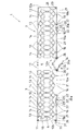
図1〜図5において、タイヤ滑り止め装置1は、タイヤ2の外周を被覆する帯状のネット体3と、このネット体3を締め付けてタイヤ2に装着させるための締結具4とを備えている。
ネット体3は、その幅方向の一方側(以下、幅方向外側ともいう)がタイヤ2の外側に装着され、幅方向の他方側(以下、幅方向内側ともいう)がタイヤ2の内側に装着されてタイヤ2外周部に巻回されるようになっている。
Hereinafter, embodiments of the present invention will be described with reference to the drawings.
1 to 5, the tire slip prevention device 1 includes a belt-like
The
ネット体3は、その帯長手方向(またはタイヤ2周方向)に所定間隔をおいて2枚並設されており、各ネット体3、3の間が開口部5とされている。この開口部5は、タイヤ滑り止め装置1をタイヤ2へ装着するときにタイヤ2の接地部分に対応する隙間となる。
各ネット体3は、所定のネット模様に張りめぐらせた芯材6に合成ゴム、天然ゴム又は合成樹脂などの非金属製の弾性材料を被覆することにより形成されるが、この実施形態では、ゴム材を加硫成形することによってネット状に形成されている。
ネット体3のネット模様は、基本単位であるネット片7を帯長手方向に複数(図例では各ネット体3は5つのネット片7からなる)並設することによって構成される。なお、各ネット片7の幅方向各端部は先細り状に形成されている。
Two
Each
The net pattern of the
ネット体3の幅方向中央部は、タイヤトレッドに対応して地面に接地するトレッド対応領域(接地領域)9とされている。このトレッド対応領域9の幅方向両側は、タイヤ2のショルダー部に対応するショルダー部対応領域10とされている。このショルダー部対応領域10の幅方向両側は、タイヤ2のサイドウォール部に対応するサイドウォール対応領域11とされている。
また、各ネット体3の帯長手方向両側は、帯幅方向に延びる細帯部12a、12bとされており、これらの細帯部12a、12bの間に所定のネット模様が形成されている。なお、2つのネット体3が対向する側の細帯部を第1細帯部12aといい、第1細帯部12aの反対側の細帯部を第2細帯部12bという。
A central portion in the width direction of the
Further, both sides of the
ネット体3の幅方向内側の端部には、タイヤ2の内側に位置してネット体3を緊締する内側緊締部13が設けられている。内側緊締部13は、各ネット片7の幅方向内側の端部、および各細帯部12a、12bのタイヤ2内側寄りの端部に設けられている。
図1に示すように、各内側緊締部13は、ネット体3の帯長手方向に沿って帯状に形成されており、内側緊締部13同士は、連結フック14によって連結されていて、タイヤ2に取り付けたときにネット体3を無端状に連結できるようになっている。
ネット体3の幅方向外側には、前記締結具4を取り付けるための取付部16が設けられている。取付部16は、ネット体3に複数形成されており、具体的には、各ネット片7の幅方向外側の端部に形成されている。
An
As shown in FIG. 1, each of the inner tightening
An
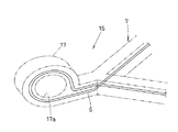
図1、図3に示すように、取付部16は、加硫成形によってネット片7と一体に形成されていて、幅方向外方に突出して形成されている。取付部16の先端部はループ状(環状)に形成されており(以下、この先端部をループ部17という)、このループ部17には帯長手方向に向いた孔17aが形成されている。
取付部16内には芯材6が設けられている。この芯材6は、ネット片7内に設けられたネット状の芯材6を延長したものであり、ループ部17のループ形状に係合してループ状に構成されている。
As shown in FIGS. 1 and 3, the
A
この芯材6のループ形状は、一本の線材を折り曲げることによって形成されている。すなわち、図2、図3に示すように、ネット片7の幅方向外端部は、網目の一辺と他の一辺が交差して先細り状とされているが、芯材6は前記網目の一辺からループ部17に向かって延長されてループを構成するように折り返され、そしてネット片7の網目の他の一辺に延長されて連結されている。
上述のように、締結具4を取り付けるための取付部16をネット体3の加硫成型処理の際に同時に形成することによって、従来のように補助金具をネット体3にカシメ等によって設けるといった行程を経ることがなくなり、これによってネット体3(タイヤ滑り止め装置1)を製造行程を短縮して製造コストを低減することができる。
The loop shape of the
As described above, by forming the
前記締結具4は、有端状の緊締索19a、19bと、この緊締索19a、19bの端部同士を接続する接続部材20a、20bとを備えている。緊締索19a、19bは各ネット体3に対として設けられている。以下、対の緊締索の一方を第1緊締索19aといい、他方を第2緊締索19bという。
各緊締索19a、19bの本体部21の一端側には、接続部材20a、20bと連結するための連結部22が設けられている。緊締索19a、19bの本体部21は、ネット体3と同様のゴム材料によってロープ状に形成されており、連結部22は、本体部21の一端部にフック体23を埋設固定することによって先端がフック状に形成されている。
The
On one end side of the
図4に示すように、フック体23のフック状の先端部とは反対の基部23aには、本体部21の内部に埋設するための埋設しろ25が設けてあり、この部分が本体部21の端部に被覆されている。このフック体23の基部23aは、本体部21の端部に被覆された状態で、本体部21の加硫成形処理の際にこの本体部21と一体に接着され、これによって、フック体23は本体部21に固定される。
緊締索19a、19bは、ネット体3の取付部16の孔17aに挿通されている。緊締索19a、19bの連結部22は、上述のようにフック体23を本体部21に埋設しているので、従来のように本体部21の先端を折り返してループ状に形成する必要がなく、この埋設部分は、嵩張ることもないので、緊締索19a、19bを取付部16の孔17aに挿通しやすくなり、タイヤ滑り止め装置1を組み立て(製造)し易くなっており、また扱いやすいものになっている。なお、この孔17aは、緊締索19a、19bの連結部22が挿通できるように、帯長手方向にやや長い長孔とされている。
As shown in FIG. 4, a base 23 a opposite to the hook-shaped tip of the
The
図1,図5に示すように、各ネット体3に設けられる対の各緊締索19a、19bの連結部22は、ネット体3の帯長手方向(またはタイヤ2の周方向)で対向して設けられており、連結部22同士が接続部材(以下、第1接続部材20aという)によって連結されている。
第1緊締索19aの連結部22とは反対の端部26は、ネット体3の第1細帯部12aにジョイント部材27を介して連結されており、一方、第2緊締索19bの連結部22とは反対の端部28は、ネット体3の第2細帯部12bにジョイント部材29を介して連結されている。
As shown in FIGS. 1 and 5, the connecting
An
第1緊締索19aの前記端部(連結部22とは反対の端部26)同士は、接続部材(以下、第2接続部材20bという)によって連結可能とされている。
また、第2緊締索19bの連結部22とは反対の端部28同士はフック状の連結体31によって連結可能とされており、連結体31によってこの端部同士を連結することで、対のネット体3同士を無端状に連結できるようになっている。
第1接続部材20aは、タイヤ滑り止め装置1をタイヤ2に装着するときに、第1緊締索19aと第2緊締索19bとを連結した状態で、ネット体3の締め付けができるようになっている。
The end portions of the first
Further, the
The first connecting
この第1接続部材20aは、工具係合体32を備えており、この工具係合体の対角部に第1緊締索19aおよび第2緊締索19bの連結部22の先端を揺動自在に連結している。
第1接続部材20aは図示しない締め付け用工具によって工具係合体32を回転操作することで、前記第1緊締索19aの連結部22と第2緊締索19bの連結部22とを、伸長状態と折り込み状態とに切り替え可能とされ、折り込み状態とすることで前記連結部22同士の間隔を狭めるように引き締めることができる。
The first connecting
The first connecting
第2接続部材20bは、第1接続部材20aと略同様の構成であり、各ネット体3の第1細帯部12aに連結されている緊締索19a、19bの端部同士を2本の連結フック34とこの第2接続部材20bとによって連結し、締め付け用工具によって第1接続部材20aと同様に折り込み状態とすることによって、ネット体3を締め付けることができる。
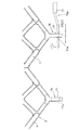
図5に示すようにタイヤ滑り止め装置1をタイヤ2に装着するには、各ネット体3の間にある開口部5をタイヤ2の接地箇所に対応させて、タイヤ2の内側に廻し込み、タイヤ2とフェンダーのすきまから引き上げて、ネット体3をタイヤ2に巻回する。
The
As shown in FIG. 5, in order to attach the tire anti-slip device 1 to the
そして、連結フック14によって内側緊締部13同士を連結し、ネット体3の幅方向内側をタイヤ2の周方向に沿って無端状に連結する。
さらに、第1接続部材20a、第2接続部材20bおよびフック状の連結体31によって、第1緊締索19aおよび第2緊締索19bが無端状に接続するとともに、各ネット体3を無端状に接続する。
その後、第1接続部材20a、第2接続部材20bを締め付け用工具によって操作して、伸張状態から折り込み状態とすると、各緊締索19a、19bは縮径するように引っ張られネット体3の幅方向外側がタイヤ径内方向に締め付けられ、装着が完了する。
Then, the
Further, the first connecting
Thereafter, when the first connecting
1 タイヤ滑り止め装置
2 タイヤ
3 ネット体
4 締結具
6 芯材
16 取付部
17a 孔
19 緊締索(19a、19b)
20 接続部材(20a、20b)
22 連結部
23 フック体
23a 基部
DESCRIPTION OF SYMBOLS 1 Tire
20 connecting members (20a, 20b)
22 connecting
Claims (3)
前記ネット体(3)の幅方向一方側には、ネット体(3)を緊締するための緊締索(19a、19b)を取り付ける取付部(16)が前記ネット体(3)と一体に形成されており、この取付部(16)は、ネット体(3)の帯長手方向に向いた孔(17a)を有するループ形状とされており、この取付部(16)内に芯材(6)がループ状に埋設固定されていることを特徴とするネット体。 In the belt-shaped net body (3) wound around the outer periphery of the tire (2), one side in the width direction is attached to the outside of the tire (2), and the other side in the width direction is attached to the inside of the tire (2).
On one side in the width direction of the net body (3), a mounting portion (16) for attaching a tightening cord (19a, 19b) for tightening the net body (3) is formed integrally with the net body (3). The attachment portion (16) has a loop shape having a hole (17a) oriented in the longitudinal direction of the band of the net body (3), and the core (6) is placed in the attachment portion (16). A net body characterized by being embedded and fixed in a loop shape.
前記緊締索(19a、19b)の一端側に、前記接続部材(20a、20b)と連結するための連結部(22)が設けられ、連結部(22)は、先端がフック状のフック体(23)の基部(23a)を緊締索(19a、19b)に埋設固定して形成されていることを特徴とするネット体の締結具。 Ended tightening cords (19a, 19b) for tightening one side in the width direction of the belt-like net body (3) wound around the outer periphery of the tire (2) and endless tightening cords (19a, 19b) In the fastener of the net body provided with connection members (20a, 20b) connected to
A connecting portion (22) for connecting to the connecting members (20a, 20b) is provided on one end side of the tightening cords (19a, 19b), and the connecting portion (22) has a hook body with a hook-like tip ( 23) A net-type fastener characterized by being formed by embedding and fixing the base portion (23a) of 23) in the fastening cords (19a, 19b).
前記締結具(4)は、ネット体(3)の幅方向一方側を緊締する有端状の緊締索(19a、19b)と、緊締索(19a、19b)を無端状に接続する接続部材(20a、20b)とを備えており、
前記ネット体(3)の幅方向一方側には、前記緊締索(19a、19b)を取り付ける取付部(16)が前記ネット体(3)と一体に形成されており、この取付部(16)は、ネット体(3)の帯長手方向に向いた孔(17a)を有するループ形状とされていて、この取付部(16)内に芯材(6)がループ状に埋設されており、
前記緊締索(19a、19b)の一端側に、前記接続部材(20a、20b)と連結するための連結部(22)が設けられ、連結部(22)は先端がフック状のフック体(23)の基部(23a)を緊締索(19a、19b)に埋設固定して形成されており、
前記緊締索(19a、19b)が前記孔(17a)に挿通されていることを特徴とするタイヤ滑り止め装置。 A belt-shaped net body (3) wound around the outer periphery of the tire (2), with one side in the width direction attached to the outside of the tire (2) and the other side in the width direction attached to the inside of the tire (2), In the tire slip prevention device provided with the fastener (4) of the net body (3),
The fastener (4) includes an end-like tightening line (19a, 19b) for tightening one side in the width direction of the net body (3), and a connecting member for connecting the tightening lines (19a, 19b) in an endless manner. 20a, 20b),
On one side in the width direction of the net body (3), an attachment portion (16) for attaching the tightening cords (19a, 19b) is formed integrally with the net body (3), and this attachment portion (16) Is a loop shape having a hole (17a) facing the longitudinal direction of the band of the net body (3), and the core material (6) is embedded in the loop in the mounting portion (16),
A connecting portion (22) for connecting to the connecting member (20a, 20b) is provided on one end side of the tightening cords (19a, 19b), and the connecting portion (22) has a hook-like hook body (23 ) Base (23a) is embedded and fixed in the tightening cords (19a, 19b),
The tire anti-skid device, wherein the tightening cords (19a, 19b) are inserted into the holes (17a).
Priority Applications (1)
| Application Number | Priority Date | Filing Date | Title |
|---|---|---|---|
| JP2004085279A JP2005271663A (en) | 2004-03-23 | 2004-03-23 | Net body and net body fastener and tire slip prevention device |
Applications Claiming Priority (1)
| Application Number | Priority Date | Filing Date | Title |
|---|---|---|---|
| JP2004085279A JP2005271663A (en) | 2004-03-23 | 2004-03-23 | Net body and net body fastener and tire slip prevention device |
Publications (1)
| Publication Number | Publication Date |
|---|---|
| JP2005271663A true JP2005271663A (en) | 2005-10-06 |
Family
ID=35171778
Family Applications (1)
| Application Number | Title | Priority Date | Filing Date |
|---|---|---|---|
| JP2004085279A Pending JP2005271663A (en) | 2004-03-23 | 2004-03-23 | Net body and net body fastener and tire slip prevention device |
Country Status (1)
| Country | Link |
|---|---|
| JP (1) | JP2005271663A (en) |
-
2004
- 2004-03-23 JP JP2004085279A patent/JP2005271663A/en active Pending
Similar Documents
| Publication | Publication Date | Title |
|---|---|---|
| JPH0330522B2 (en) | ||
| JP2005271663A (en) | Net body and net body fastener and tire slip prevention device | |
| JPH0340641Y2 (en) | ||
| JPH034564Y2 (en) | ||
| JP2719342B2 (en) | Tire anti-slip device | |
| JPH057043Y2 (en) | ||
| JPH04964Y2 (en) | ||
| JP2525992B2 (en) | Tire anti-skid device | |
| JPH02322Y2 (en) | ||
| JP2888277B2 (en) | Anti-slip device for tires | |
| JPH0611202Y2 (en) | Tire anti-skid coupling | |
| JPS6347523Y2 (en) | ||
| JPS581365Y2 (en) | Girdle structure attached to rubber wheels | |
| JP3986164B2 (en) | Anti-slip device for tire | |
| JP2661713B2 (en) | Tire anti-slip device | |
| JP2575416Y2 (en) | Tension band with joint hook for tire anti-slip device | |
| JP3385171B2 (en) | Anti-slip device for tires | |
| JP2524959B2 (en) | Tire slipper | |
| JPS6325112A (en) | Non-skid device for tire | |
| JPH0420647Y2 (en) | ||
| JPH067925Y2 (en) | Tire anti-skid coupling | |
| JP2005001568A (en) | Antiskid for tire | |
| JPH0323363Y2 (en) | ||
| JP2524962B2 (en) | Tire slipper | |
| JPH0596918A (en) | Tire antiskid device |