JP2005254973A - Snow vehicle - Google Patents
Snow vehicle Download PDFInfo
- Publication number
- JP2005254973A JP2005254973A JP2004069032A JP2004069032A JP2005254973A JP 2005254973 A JP2005254973 A JP 2005254973A JP 2004069032 A JP2004069032 A JP 2004069032A JP 2004069032 A JP2004069032 A JP 2004069032A JP 2005254973 A JP2005254973 A JP 2005254973A
- Authority
- JP
- Japan
- Prior art keywords
- engine
- intake
- vehicle body
- air cleaner
- snow
- Prior art date
- Legal status (The legal status is an assumption and is not a legal conclusion. Google has not performed a legal analysis and makes no representation as to the accuracy of the status listed.)
- Pending
Links
Images


Classifications
-
- B—PERFORMING OPERATIONS; TRANSPORTING
- B62—LAND VEHICLES FOR TRAVELLING OTHERWISE THAN ON RAILS
- B62M—RIDER PROPULSION OF WHEELED VEHICLES OR SLEDGES; POWERED PROPULSION OF SLEDGES OR SINGLE-TRACK CYCLES; TRANSMISSIONS SPECIALLY ADAPTED FOR SUCH VEHICLES
- B62M27/00—Propulsion devices for sledges or the like
- B62M27/02—Propulsion devices for sledges or the like power driven
-
- F—MECHANICAL ENGINEERING; LIGHTING; HEATING; WEAPONS; BLASTING
- F02—COMBUSTION ENGINES; HOT-GAS OR COMBUSTION-PRODUCT ENGINE PLANTS
- F02M—SUPPLYING COMBUSTION ENGINES IN GENERAL WITH COMBUSTIBLE MIXTURES OR CONSTITUENTS THEREOF
- F02M35/00—Combustion-air cleaners, air intakes, intake silencers, or induction systems specially adapted for, or arranged on, internal-combustion engines
- F02M35/10—Air intakes; Induction systems
- F02M35/104—Intake manifolds
- F02M35/108—Intake manifolds with primary and secondary intake passages
-
- F—MECHANICAL ENGINEERING; LIGHTING; HEATING; WEAPONS; BLASTING
- F02—COMBUSTION ENGINES; HOT-GAS OR COMBUSTION-PRODUCT ENGINE PLANTS
- F02M—SUPPLYING COMBUSTION ENGINES IN GENERAL WITH COMBUSTIBLE MIXTURES OR CONSTITUENTS THEREOF
- F02M35/00—Combustion-air cleaners, air intakes, intake silencers, or induction systems specially adapted for, or arranged on, internal-combustion engines
- F02M35/10—Air intakes; Induction systems
- F02M35/104—Intake manifolds
- F02M35/112—Intake manifolds for engines with cylinders all in one line
-
- F—MECHANICAL ENGINEERING; LIGHTING; HEATING; WEAPONS; BLASTING
- F02—COMBUSTION ENGINES; HOT-GAS OR COMBUSTION-PRODUCT ENGINE PLANTS
- F02M—SUPPLYING COMBUSTION ENGINES IN GENERAL WITH COMBUSTIBLE MIXTURES OR CONSTITUENTS THEREOF
- F02M35/00—Combustion-air cleaners, air intakes, intake silencers, or induction systems specially adapted for, or arranged on, internal-combustion engines
- F02M35/16—Combustion-air cleaners, air intakes, intake silencers, or induction systems specially adapted for, or arranged on, internal-combustion engines characterised by use in vehicles
- F02M35/162—Motorcycles; All-terrain vehicles, e.g. quads, snowmobiles; Small vehicles, e.g. forklifts
-
- B—PERFORMING OPERATIONS; TRANSPORTING
- B62—LAND VEHICLES FOR TRAVELLING OTHERWISE THAN ON RAILS
- B62M—RIDER PROPULSION OF WHEELED VEHICLES OR SLEDGES; POWERED PROPULSION OF SLEDGES OR SINGLE-TRACK CYCLES; TRANSMISSIONS SPECIALLY ADAPTED FOR SUCH VEHICLES
- B62M27/00—Propulsion devices for sledges or the like
- B62M27/02—Propulsion devices for sledges or the like power driven
- B62M2027/023—Snow mobiles characterised by engine mounting arrangements
Abstract
Description
本発明は、エンジンの前方に操舵軸を設け、エンジンの後方にエアクリーナを含む吸気装置を配置した雪上車に関する。 The present invention relates to a snow vehicle in which a steering shaft is provided in front of an engine and an air intake device including an air cleaner is disposed behind the engine.
従来、エンジンの後方に操舵軸を設け、エンジンと操舵軸との間に吸気装置を配置した雪上車が知られている(例えば、特許文献1参照。)。
特許文献1の図1において、符号1は雪上車、符号2はエンジン、符号25は操舵軸であり、エンジン2の後方に操舵軸25を配置し、エンジン2本体と操舵軸25の間に吸気経路を配置する。そして、雪上車1の進行方向に対しエンジン2を後傾させて、車体フレーム10にエンジン2を搭載した雪上車1である。
In FIG. 1 of Patent Document 1, reference numeral 1 is a snow vehicle, reference numeral 2 is an engine,
操舵軸25の前方にエンジン2を配設することにより、車体上のエンジン2の設置高さを低く抑えて車体の低重心化を図り、雪上車1の旋回性能を高めるというものである。
By disposing the engine 2 in front of the
しかし、操舵軸25を挟んで前方にエンジン2を配設し、操舵軸25を挟んで後方に乗員が乗車するため、エンジン2と乗員の間隔を狭めるには限度がある。
すなわち、エンジン2の質量と乗員の質量を車体の中心に集めることが難しく、車両の慣性モーメントを低減するには限度がある。
However, since the engine 2 is disposed in front of the
That is, it is difficult to collect the mass of the engine 2 and the mass of the occupant at the center of the vehicle body, and there is a limit to reducing the moment of inertia of the vehicle.
エンジン2と乗員の間隔を狭くすることにより質量を車体の中心に集めることができれば、慣性モーメントを低減でき、雪上車1の旋回性能を高めることができ、より快適な走行を行うことができる。 If the mass can be collected at the center of the vehicle body by narrowing the distance between the engine 2 and the occupant, the moment of inertia can be reduced, the turning performance of the snow vehicle 1 can be improved, and more comfortable traveling can be performed.
そこで、本発明は、エンジンと乗員の配置を狭め、質量の集中化を図り、走行時の快適性を高めることを課題とする。 Therefore, an object of the present invention is to narrow the arrangement of the engine and the occupant, to concentrate the mass, and to improve the comfort during traveling.
請求項1に係る発明は、車体前部に配置したエンジンによって車体後方に設けたトラックベルトを駆動すると共に、車体前部に設けた左右一対のスキーをハンドル操作によって操舵する雪上車において、エンジンのシリンダを後傾させると共に、エンジンの前方に操舵軸を通し、エンジン後方にエアクリーナを含む吸気装置を設けることを特徴とする。 The invention according to claim 1 is a snow vehicle in which a track belt provided at the rear of the vehicle body is driven by an engine disposed at the front portion of the vehicle body and a pair of left and right skis provided at the front portion of the vehicle body are steered by steering operation. The cylinder is tilted rearward, a steering shaft is passed in front of the engine, and an intake device including an air cleaner is provided in the rear of the engine.
請求項2に係る発明は、エンジンへ連通する吸気通路に設けたスロットルボディに燃料噴射用インジェクタを一体に設け、このインジェクタはスロットルボディの上側に設けたことを特徴とする。 The invention according to claim 2 is characterized in that a fuel injection injector is integrally provided in a throttle body provided in an intake passage communicating with the engine, and the injector is provided on an upper side of the throttle body.
請求項3に係る発明は、車体前部に配置したエンジンによって車体後方に設けたトラックベルトを駆動すると共に、車体前部に設けた左右一対のスキーをハンドル操作によって操舵する雪上車において、エンジンの後方にエアクリーナを設け、エアクリーナはエアを濾過するためのエレメントを挟んで上部に上室を、下部に下室を設け、上室の左右両側面にエア取入れのための吸気ダクトを設け、上室の上面にメンテナンスのためのメンテリッドを備えることを特徴とする。 According to a third aspect of the present invention, there is provided a snow vehicle that drives a track belt provided at the rear of a vehicle body by an engine disposed at a front portion of the vehicle body and steers a pair of left and right skis provided at the front portion of the vehicle body by a steering operation. An air cleaner is provided at the rear, the air cleaner has an upper chamber with an element for filtering air, a lower chamber in the lower portion, air intake ducts for intake of air on the left and right sides of the upper chamber, It is characterized by having a maintenance maintenance on the upper surface.
請求項4に係る発明は、吸気ダクトは、吸気口が下方を向くように屈曲させたことを特徴とする。 The invention according to claim 4 is characterized in that the intake duct is bent so that the intake port faces downward.
請求項5に係る発明は、上室の左右両側面に吸気ダクトの後端開口部を対向させ、所定間隔をもたせて備えたことを特徴とする。 The invention according to claim 5 is characterized in that the rear end opening of the intake duct is opposed to both the left and right side surfaces of the upper chamber, and is provided with a predetermined interval.
請求項6に係る発明は、車体前部に配置したエンジンによって車体後方に設けたトラックベルトを駆動すると共に、車体前部に設けた左右一対のスキーをハンドル操作によって操舵する雪上車において、エンジンの後方にエアクリーナを設け、エアクリーナはエアを濾過するためのエレメントを挟んで上部に上室を、下部に下室を設け、下室の内部に複数の吸気管を設け、これらの吸気管はエアクリーナケースにセットプレートにより取付けたことを特徴とする。 According to a sixth aspect of the present invention, there is provided a snow vehicle that drives a track belt provided at the rear of a vehicle body by an engine disposed at a front portion of the vehicle body and steers a pair of left and right skis provided at the front portion of the vehicle body by a steering operation. An air cleaner is provided at the rear, the air cleaner has an upper chamber with an air filter element in between, an upper chamber in the upper portion, a lower chamber in the lower portion, and a plurality of intake pipes in the lower chamber. These intake pipes are air cleaner cases. It is characterized by being attached to a set plate.
請求項7に係る発明は、吸気管の外壁に突片部を設け、セットプレートに突片部を挿入するためのスリット部を設け、このスリット部に突片部を連通し、突片部を所定角度だけ回転することによりエアクリーナケースに吸気管を位置決め、固定することを特徴とする。 The invention according to claim 7 is provided with a protruding piece portion on the outer wall of the intake pipe, a slit portion for inserting the protruding piece portion into the set plate, the protruding piece portion communicating with the slit portion, The intake pipe is positioned and fixed to the air cleaner case by rotating by a predetermined angle.
請求項1に係る発明では、エンジンのシリンダを後傾させた。この結果、エンジンの重心は車体後方に寄る。前記エンジンの後傾配置に加え、前記エンジンの前方に操舵軸を設けたので、エンジンの低重心化を図れると共に、車体全体の重心を車体中心寄りに設定することができる。
従って、車体の重心を車体中心近傍に集中化することができ、旋回性能を向上させることができるという利点がある。
In the invention according to claim 1, the cylinder of the engine is tilted backward. As a result, the center of gravity of the engine approaches the rear of the vehicle body. Since the steering shaft is provided in front of the engine in addition to the rearward tilt arrangement of the engine, the center of gravity of the engine can be lowered, and the center of gravity of the entire vehicle body can be set closer to the center of the vehicle body.
Therefore, there is an advantage that the center of gravity of the vehicle body can be concentrated in the vicinity of the vehicle body center and the turning performance can be improved.
請求項2に係る発明は、エンジンへ連通する吸気通路に設けたスロットルボディに燃料噴射用インジェクタを一体に設け、このインジェクタはスロットルボディの上側に設けたので、燃料のガスたまりを防止することができる。 加えて、インジェクタの組付け性を向上することができる。 In the invention according to claim 2, since the fuel injection injector is integrally provided in the throttle body provided in the intake passage communicating with the engine, and this injector is provided on the upper side of the throttle body, it is possible to prevent fuel gas accumulation. it can. In addition, the assembly property of the injector can be improved.
請求項3に係る発明では、上室の上面にメンテリッドを備えたので、エレメントの状態を容易に確認でき、エレメントの脱着を容易に行うことができるという利点がある。 In the invention which concerns on Claim 3, since the maintenance was provided in the upper surface of the upper chamber, there exists an advantage that the state of an element can be confirmed easily and removal | desorption of an element can be performed easily.
請求項4に係る発明では、吸気ダクトは、吸気口が下方を向くように屈曲させたので、吸気口からの雪や氷等の水分の侵入を抑制することができるという利点がある。 In the invention according to claim 4, since the intake duct is bent so that the intake port faces downward, there is an advantage that intrusion of moisture such as snow and ice from the intake port can be suppressed.
請求項5に係る発明では、吸気ダクトの後端開口部を所定間隔にて対向配置したので、一方の閉塞を補完することができるという利点がある。 In the invention which concerns on Claim 5, since the rear-end opening part of the intake duct was opposingly arranged by predetermined spacing, there exists an advantage that one obstruction | occlusion can be supplemented.
請求項6に係る発明では、吸気管は、エアクリーナケースに、セットプレートにより取付けたので、各吸気管ごとに取付けのための締結部材等を用意する必要はなく、セットプレートで代用することができる。
セットプレートで代用できるため、必要な締結部材の数を減らすことができるという利点がある。
In the invention according to
Since the set plate can be substituted, there is an advantage that the number of necessary fastening members can be reduced.
請求項7に係る発明では、セットプレートに前記突片部を挿入するためのスリット部を設け、突片部を所定角度だけ回転することによりエアクリーナケースに吸気管を位置決め、固定したので、吸気管を位置決め、固定する作業を簡便に行える。
この結果、エアクリーナケースへの吸気管の組立工数の低減を図ることができるという利点がある。
In the invention according to claim 7, the slit portion for inserting the protruding piece portion is provided in the set plate, and the intake pipe is positioned and fixed to the air cleaner case by rotating the protruding piece portion by a predetermined angle. Positioning and fixing can be performed easily.
As a result, there is an advantage that the number of assembling steps of the intake pipe to the air cleaner case can be reduced.
本発明を実施するための最良の形態を添付図に基づいて以下に説明する。なお、図面は符号の向きに見るものとする。 The best mode for carrying out the present invention will be described below with reference to the accompanying drawings. The drawings are viewed in the direction of the reference numerals.
本発明を実施するための最良の形態を添付図に基づいて以下に説明する。なお、図面は符号の向きに見るものとする。また、Lは運転者から見て左、Rは同右を表す添え字である。 The best mode for carrying out the present invention will be described below with reference to the accompanying drawings. The drawings are viewed in the direction of the reference numerals. Further, L is a subscript indicating the left when viewed from the driver, and R is a subscript indicating the right.
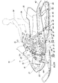
図1は本発明に係る雪上車の全体側面図であり、雪上車10は、車体11に前から後へ、左右一対のスキー12L、12R(12Rは12Lの陰。以下同様)、エンジン13及びトラックベルト14をこの順に備え、エンジン13の動力でトラックベルト14を駆動することで走行し、スキー12L、12Rをハンドル15の操作によって、操舵することのできる雪上乗り物である。そして、車体前部に設けたエンジン13の後方に乗員が座るシート24を設け、このシート24下部に燃料タンク25を前後に長く設ける。
FIG. 1 is an overall side view of a snow vehicle according to the present invention. A
Mは乗員、13aはシリンダヘッドカバー、13bはシリンダヘッド、13cはシリンダ、16は車体カバー、17はエアクリーナ、18はオイルタンク、19は排気管、21は触媒、22はサイレンサ、23はテールパイプ、57はスロットルバルブ、57aはスロットルボディ、58はインジェクタである。 M is an occupant, 13a is a cylinder head cover, 13b is a cylinder head, 13c is a cylinder, 16 is a body cover, 17 is an air cleaner, 18 is an oil tank, 19 is an exhaust pipe, 21 is a catalyst, 22 is a silencer, 23 is a tail pipe, 57 is a throttle valve, 57a is a throttle body, and 58 is an injector.
先ず、吸排気系統を説明すると、エアクリーナ17で吸入したエアはエンジン13の燃焼室に至る。燃焼により発生する排気は、排気管19、触媒21、サイレンサ22、テールパイプ23を通じて大気へ放出する。
テールパイプ23は、サイレンサ22から出た後に図面奥へ進み、次に下降することで、排気を雪面へ吹付ける形状にした。
燃料タンク25とエンジン13との間に、エアクリーナ17を配置したので、エアクリーナ17のメンテナンスを容易に行うことができる。
First, the intake / exhaust system will be described. The air sucked by the
After the
Since the
次に、走行系統を説明すると、車体フレームにエンジンハンガー26L、26R、27L、27Rを介してエンジン13を載置し、このエンジン13のクランク軸28に駆動プーリ31を嵌める。
Next, the traveling system will be described. The
この駆動プーリ31と、エアクリーナ17の下に配置した従動プーリ32とにCVTベルト33を掛け渡すことで、ベルト式無段変速装置30を構成する。従動プーリ32を支えるクロス軸34を図面奥へ延ばし、先端にスプロケット35を取付け、このスプロケット35と、駆動輪36に付設したスプロケット37とにチェーン38を掛け渡す。
The belt type continuously
エンジン13の動力を、駆動プーリ31、CVTベルト33、従動プーリ32、クロス軸34、スプロケット35、チェーン38、スプロケット37の順に伝えることで、駆動輪36を正転若しくは逆転させることができる。
By transmitting the power of the
トラックベルト14は、前部に配置した駆動輪36と、後部に配置した従動輪39と、中間下部に配置した複数の転輪41と、上部に配置したアイドラ42とに巻き掛け、外面に備える突起43を雪面に食い込ませることで、走行する。雪面上の凹凸などを乗り越えるときに発生する上下動はリヤクッション44、45で吸収させる。
The
なお、エンジン13のシリンダ13cを後傾して配置させた。すなわち、エンジン13のシリンダヘッド13bを鉛直軸から後方に角度θだけ傾けて配置した。
In addition, the
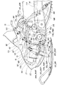
図2は本発明に係る雪上車の前部側面図であり、ハンドル15とスキー12L、12Rとは、次に述べる操舵軸55及びリンク類を用いて連結する。
なお、57はエアクリーナ17の下流側に設けたスロットルバルブ、58はそれより下流側に設けたインジェクタである。
FIG. 2 is a front side view of the snow vehicle according to the present invention, and the
In addition, 57 is a throttle valve provided on the downstream side of the
エンジン13へ連通する吸気通路に設けたスロットルバルブ57を構成するスロットルボディ57aに、燃料噴射用インジェクタ58を一体に設け、このインジェクタ58はスロットルボディ57aの上側に設けたので、燃料のガスたまりを防止することができる。加えて、インジェクタ58の組付け性を向上することができる。
A
操舵軸55は、上端にハンドルホルダ151を備えるとともに前方下方へ傾斜させた操舵軸上部52と、この操舵軸上部52の下端に取付けたユニバーサル型自在継手53と、この自在継手53からほぼ鉛直に下げた操舵軸下部54とからなる。
The steering
そして、操舵軸下部54の下端にレバー155を設け、このレバー155に車幅方向(図面表裏方向)へ延ばした駆動メンバー156を連結し、この駆動メンバー156の左右端に各々レバー157を取付け、このレバー157で縦向きのスピンドル158L、158Rを略鉛直軸回りに回転させることで、スキー12L、12Rを操舵することができる。
Then, a lever 155 is provided at the lower end of the steering shaft
なお、スピンドル158L、158Rは、車体フレームに上下動可能に取付けた下部アーム80L、80R、上部アーム90L、90R及びフロントサスペンション164L、164Rで上下動可能に支持した前脚部59L、59Rに回転自在に収納する。
The
また、サイレンサ22を、エンジン13の前方(図左)に配置し、操舵軸55のうちの操舵軸下部54は、サイレンサ22とエンジン13との間を通したことを特徴とする。
エンジン13を操舵軸下部54より後方に配置した。すなわち操舵軸下部54をエンジン13の前に配置したので、エンジン13を容易に後方へ移動することができる。
Further, the
The
ところで、操舵軸下部54は、サイレンサ22の前方を通す構造と、サイレンサ22とエンジン13との間を通す構造との二通りの構造が考えられる。
サイレンサ22の前方を通すと操舵軸55が全体的に長くなる。この点、本発明では、操舵軸下部54を、サイレンサ22とエンジン13との間を通したので、操舵軸55の短縮化が容易に達成できる。
By the way, the steering shaft
When the front of the
加えて、操舵軸55の途中に、自在継手53を介在させ、操舵軸下部54をエンジン13に接近させたことを特徴とする。
操舵軸下部54をエンジン13に接近させることができれば、連動してサイレンサ22をもエンジン13に接近させることができる。この結果、車体前後方向における質量の集中化が達成できる。
In addition, a
If the steering shaft
車体フレーム176は、トラックベルト14の上面及び左右側面を跨ぐように下方へ開口したコ字断面の後部フレーム177の前部に、側面視U字を呈する中間フレーム178L、178Rを接続し、この中間フレーム178L、178Rの前部に前部フレーム179を接続したフレームであって、中間フレーム178L、178Rに次に述べる補強を施したことを特徴とする。
The
中間フレーム178L、178Rはクランク軸28などを通すことができるように、切欠き部181を有する側面視U字フレームとした。U字フレームであるため適当な補強を施すことが望ましい。
そこで、切欠き部181に沿ってL字補強材182及びI字補強材183を中間フレーム178L、178Rに付設することで切欠き部181を補強する。
The
Therefore, the L-shaped reinforcing member 182 and the I-shaped reinforcing
更に、前部フレーム179の上部と、後部フレーム177の前部上部とを、切欠き部181を跨ぐようにサイドフレーム47L、47Rで接続する。具体的には、前部フレーム179にフロントサスペンション164L、164Rを取付けるが、そのためのサスペンション受け部185の近傍に、サイドフレーム47L、47Rの先端を接続する。そして、後部フレーム177にリヤクッション44を取付けるが、そのためのクッション受け部186の近傍に、サイドフレーム47L、47Rの後端を接続する。
これで、前部フレーム179と後部フレーム177を、強固に結合することができる。
Further, the upper part of the
Thus, the
図3は本発明に係る雪上車の前部平面図(車体カバーは省略)であり、車体11の構成要素である左右のサイドフレーム47L、47Rに左右のクリーナ固定ブラケット48L、48Rを介して、上方からエアクリーナ17を載置し、エアクリーナ17の一部として固定部46L、46Rを左右に延設し、これらの固定部46L、46Rとクリーナ固定ブラケット48L、48R(以下、ブラケットと呼ぶ。)とを締結手段49L、49Rで挟持することにより締結する。
FIG. 3 is a front plan view of a snow vehicle according to the present invention (the vehicle body cover is omitted), and left and right side frames 47L and 47R, which are components of the
エンジン13の前方に、操舵軸上部52、自在継手53、操舵軸下部54とからなる操舵軸55を設けた。そして、前述したように、エンジン13後方にエアクリーナ17を含む吸気装置20を設けた。
A steering
なお、51はエアクリーナ17からエンジン13にエアを供給するためのエア供給パイプ、56L、56Rは左右のフロントサスペンション、57はスロットルバルブ、58はインジェクタ、59L、59Rは左右の前脚部、60は駆動メンバーである。
Note that 51 is an air supply pipe for supplying air from the
図4は本発明に係るエアクリーナの分解斜視図であり、エアクリーナ11は、エレメントを備えるエレメントケース76と、このエレメントケース76を収納する上部ケース68と、この上部ケース68に被せるメンテリッド67と、上部ケース68の左右側面に付属する吸気ダクト65L、65Rと、上部ケース68の底に連結する下部ケース69と、この下部ケース69に収納する吸気管93・・・と、これらの吸気管93を下部ケース69に固定するセットプレート92と、下部ケース69を塞ぐ蓋部96とから構成する。
FIG. 4 is an exploded perspective view of the air cleaner according to the present invention. The
そして、下部ケース69の下部前側面69fの内部にセットプレート92を取付け、セットプレート92に吸気管93・・・を差込んで取付け、蓋部96により蓋をする。
次に、前記下部ケース69の上面開口部71に上方から上部ケース68を嵌め、エレメントを囲うエレメントケース76を嵌め、エレメントケース76の上にリッド固定部材98を介してメンテリッド67を取付ける。
Then, the
Next, the
最後に、上部ケース68の左右側面68a、68bに吸気ダクト65L、65Rを取付ける。組立が完了したエアクリーナ17の断面構成を次に説明する。
Finally, the
図5は本発明に係るエアクリーナの断面図であり、エレメントケース76は鍔部77を備えた筒体に整流羽根94を一体的に備えた部品であり、整流羽根94にエレメント61を付設することができる。
そして、エア99を濾過するためのエレメント61の上部に上室62を、下部に下室63を設ける。すなわち、上室62を形成する部材が上部ケース68であり、下室63を形成する部材が下部ケース69である。
FIG. 5 is a cross-sectional view of the air cleaner according to the present invention, and the
And the
サイドフレーム47にブラケット48を介して下部ケース69を固定し、この下部ケース69の上面69tに設けた開口穴71に、上部ケース68下面の開口部72の周囲に設けた側部73を嵌合する。
The
下部ケース69への上部ケース68の取付け方法は、接着剤によるが、溶着あるいは、嵌合による方法でも差し支えない。
そして、上部ケース68の内部に形成した凸部74に、エレメントケース76下部の鍔部77の下向きの面に備えた凹部78を嵌める。
A method of attaching the
And the recessed
次に、エレメントケース76の周囲に縦部材79を付設し、これらの縦部材79の上面81にメンテリッド67の下面83から脚部84を下方に延ばし、脚部84の先端84aを縦部材79の上面81に当接させる。
従って、上部ケース69の凸部74と、エレメントケース76の凹部78及び縦部材79の上面81と、メンテリッド67の脚部84の先端84aとにより、上部ケース68の上室62の内部にエレメントケース76を固定することができる。
Next, a
Therefore, the
上室62の左右両側面64L、64R(64Lの反対側の面)に後端開口部86L、86Rを対向させて開け、左右から吸気ダクト65L、65Rを取付ける。吸気ダクト65L、65Rは、吸気口88、88が下方を向くように屈曲させて形成する。
The
下部ケース69下部の前側面69fにエア出力穴91を設け、エア出力穴91にセットプレート92を介して吸気管93を取付ける。
エア出力穴91に対向する面である下部ケース69下部の後側面69rは大開口部95であり、この大開口部95を塞ぐため蓋部96を取付ける。
An
A
図6は図5の6矢視図(蓋部96は取外した。)であり、上室62の左右両側面64L、64Rにエア取入れのための吸気ダクト65L、65Rを配設する。
上部ケース吸気ダクト65L、65Rの後端開口部86L、86Rを所定間隔にて対向配置したので、一方の閉塞を補完することができる。
6 is a view taken in the direction of
Since the
図において、下部ケース69の蓋部96(図4参照)を取外した状態で、セットプレート92と、このセットプレート92に取付けた複数の吸気管93・・・(・・・は複数個を示す。以下同じ)を視認することができる。これらの吸気管93・・・の取付け構造については、後で詳しく説明する。
In the figure, with the cover 96 (see FIG. 4) of the
次に、エアクリーナ17の作用につき説明する。
左右に配置した吸気ダクト65L、65Rの吸気口88から吸入したエア99は、上部ケース68に入り、上方から回り込んでエレメントケース76で囲んだエレメント61(図3参照)で濾過され、下部ケース69に入り、下部ケース69に取付けた吸気管93・・・を通過する。
Next, the operation of the
The
図5に戻って、吸気管93を通過したエア99は、エア供給パイプ51に入り、エンジン側に供給される。
吸気ダクト65L、65Rは、吸気口88が下方を向くように屈曲させたので、吸気口88からの雪や氷等の水分の侵入を抑制することができる。
Returning to FIG. 5, the
Since the
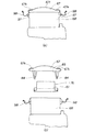
図7はエアクリーナの脱着要領図であり、エレメント61のチェックやエレメント61の交換等のメンテナンスが容易に実施できることを示す。
(a)において、上部ケース68の側面の支軸97に備えたリッド固定部材98をメンテリッド67の上面67tに備えた嵌合部67kから外す。
FIG. 7 is a diagram showing how the air cleaner is attached and detached, and shows that maintenance such as checking of the
In (a), the
(b)において、メンテリッド67を上方に取外すと共に、メンテリッド67の下面83から下方に突出して備えたリッドの脚部84が規制していたエレメントケース76を持上げる。リッド脚部84の規制が外れるので、エレメント61を内蔵したエレメントケース76を上部ケース68から簡単に取外すことができる。
従って、エレメント61の状態を容易に確認できると共に、エレメント61の脱着を容易に行うことができる。
In (b), while removing the
Therefore, the state of the
図8は本発明に係る吸気管及びセットプレートの斜視図であり、以下、各吸気管93の取付け関係は同様であるため、1つの吸気管93で説明する。
下室63の内部に吸気管93を設け、吸気管93はエアクリーナケース112にセットプレート92により取付けた。エアクリーナケース112は、本実施例においては、下部ケース69を指す。
FIG. 8 is a perspective view of the intake pipe and the set plate according to the present invention. Hereinafter, since the attachment relationship of each
An
下部ケース69は、その下部前側面69fに開けたエア出力穴91の周囲に対角状に配置した小凸部113、113と、これらの小凸部113、113の端部に配置したストッパ部114、114とを備えた部材である。
セットプレート92は、フランジ部116とフランジ部116同士を連結する連結部117とからなる。
The
The
フランジ部116は、吸気管差込穴118と、吸気管差込穴118の周囲に対角状に配置したスリット部119、119を備える部材である。一方、連結部117は、セットプレート取付け用穴121・・・を備えた部材である。
吸気管93は、その一端の周囲に対角状に配置した2つの突片部122、122を備える部材である。
The
The
そして、あらかじめ、下部ケース69に締結ボルト123・・・を介してセットプレート92を取付けておき、このセットプレート92に備えたスリット部119、119に吸気管93の突片部122、122を差込み、吸気管93を所定の角度に回動することにより取付ける。
The
吸気管93は、エアクリーナケース112に、セットプレート92により取付けるので、各吸気管93ごとに取付けのための締結部材等を用意する必要はなく、セットプレート92で代用することができる。
セットプレート92で代用できるため、必要な締結部材の数を減らすことができる。
Since the
Since the
図8は図7の作用図であり、吸気管93の外壁93aに突片部122を設け、セットプレート92に突片部122を挿入するためのスリット部119を設け、このスリット部部119に突片部122を連通し、突片部122を所定角度だけ回転することによりエアクリーナケース112に吸気管93を位置決め、固定する。
FIG. 8 is an operation diagram of FIG. 7. A projecting
(a)は、吸気管93の中心軸125を、鉛直軸126から角度θaだけ左側に傾けた状態で、スリット部119の位置に合わせ、吸気管93の突片部122を差込んだことを示す。
(b)は(a)のb−b線断面図であり、突片部122の先端面122fは、下部ケースに設けた小凸部113の表面113aに当接した状態にある。
(A) shows that the projecting
(B) is a sectional view taken along the line bb of (a), and the
(c)において、吸気管93の中心軸125を角度θaから角度θb(θb<θa)まで回動した状態である。
(d)は(c)のd−d線断面図であり、突片部122の先端面122fは、下部ケースに設けた小凸部113の表面113aに当接し、突片部122の後端面122rは、セットプレート92のフランジ裏面116rに当接し、吸気管93の外壁93aは、セットプレート92のフランジ内周面116iに当接した状態にある。すなわち、吸気管93は、下部ケース69とセットプレート92とにより規制されながら回動する。
In (c), the
(D) is a sectional view taken along the line dd of (c), and the
(e)において、吸気管93の中心軸125を角度θbから(0<θb)鉛直軸126と一致するまで回動した状態にある。
In (e), the
(f)は(e)のf−f線断面図であり、突片部122の先端面122fは、下部ケース69に設けたセット部127に接し、突片部122の後端面122rは、セットプレート92のフランジ裏面116rに当接し、吸気管93の外壁93aは、セットプレート92のフランジ内周面116iに当接した状態にある。
(F) is a sectional view taken along the line ff of (e), the
このとき、吸気管93の突片部122の外周面122g及びセットプレート92のフランジ内周部116iの寸法を各々所定の公差内に設定し、回動した吸気管93をセットプレート92及び下部ケース69に固定することができる。
At this time, the dimensions of the outer
セットプレート92に突片部122を挿入するためのスリット部部119を設け、突片部122を所定角度だけ回転することによりエアクリーナケース112に吸気管93を位置決め、固定するので、吸気管93を位置決め、固定する作業を簡便に行える。
この結果、エアクリーナケース112に吸気管93を確実に取付けられる。加えて、組立工数の低減を図ることができる。
A
As a result, the
また、図1に戻って、エンジン13の後傾配置に加え、エンジン13の前方に操舵軸55を通し、エンジン13を構成するシリンダ13cの後方にエアクリーナ17を含む吸気装置20を設けたので、エンジンの低重心化を図ることができ車体全体の重心を車体中心寄りに近づけることができる。
この結果、旋回性能を向上させることができ、より快適な走行をすることができる。
Returning to FIG. 1, in addition to the backward tilting arrangement of the
As a result, the turning performance can be improved and more comfortable traveling can be performed.
本発明は、雪上車に好適である。 The present invention is suitable for snow vehicles.
10…雪上車、12L、12R…スキー、13…エンジン、14…トラックベルト、17…エアクリーナ、24…シート、25…燃料タンク、31…吸気装置、55…操舵軸、61…エレメント、62上室、63…下室、64L、64R…上室の側面、65L。65R…吸気ダクト、67…メンテリッド、68…上部ケース、69…下部ケース、76…エレメントケース、88…吸気ダクトの吸気口、92…セットプレート、93…吸気管、93a…吸気管の外壁、112…エアクリーナケース、122…吸気管の突片部。
DESCRIPTION OF
Claims (7)
前記エンジンのシリンダを後傾させると共に、前記エンジンの前方に操舵軸を通し、前記エンジンシリンダの後方にエアクリーナを含む吸気装置を設けることを特徴とする雪上車。 In a snow vehicle that drives a track belt provided at the rear of the vehicle body by an engine disposed at the front of the vehicle body and steers the pair of left and right skis provided at the front of the vehicle body by steering operation,
A snow vehicle characterized in that a cylinder of the engine is tilted backward, a steering shaft is passed in front of the engine, and an intake device including an air cleaner is provided in the rear of the engine cylinder.
前記エンジンの後方にエアクリーナを設け、前記エアクリーナはエアを濾過するためのエレメントを挟んで上部に上室を、下部に下室を設け、
前記上室の左右両側面にエア取入れのための吸気ダクトを設け、前記上室の上面にメンテナンスのためのメンテリッドを備えることを特徴とする雪上車。 In a snow vehicle that drives a track belt provided at the rear of the vehicle body by an engine disposed at the front of the vehicle body and steers the pair of left and right skis provided at the front of the vehicle body by steering operation,
An air cleaner is provided at the rear of the engine, and the air cleaner has an upper chamber at the top and a lower chamber at the lower portion with an element for filtering air,
A snow vehicle characterized in that air intake ducts for air intake are provided on both left and right side surfaces of the upper chamber, and maintenance is provided on the upper surface of the upper chamber.
前記エンジンの後方にエアクリーナを設け、前記エアクリーナはエアを濾過するためのエレメントを挟んで上部に上室を、下部に下室を設け、
前記下室の内部に複数の吸気管を設け、これらの吸気管はエアクリーナケースにセットプレートにより取付けたことを特徴とする雪上車。 In a snow vehicle that drives a track belt provided at the rear of the vehicle body by an engine disposed at the front of the vehicle body and steers the pair of left and right skis provided at the front of the vehicle body by steering operation,
An air cleaner is provided at the rear of the engine, and the air cleaner has an upper chamber at the top and a lower chamber at the lower portion with an element for filtering air,
A snow vehicle characterized in that a plurality of intake pipes are provided inside the lower chamber, and these intake pipes are attached to an air cleaner case by a set plate.
Priority Applications (3)
| Application Number | Priority Date | Filing Date | Title |
|---|---|---|---|
| JP2004069032A JP2005254973A (en) | 2004-03-11 | 2004-03-11 | Snow vehicle |
| US11/063,659 US7353899B2 (en) | 2004-03-11 | 2005-02-23 | Snowmobile with improved air intake structure |
| CA002499451A CA2499451C (en) | 2004-03-11 | 2005-03-04 | Snowmobile |
Applications Claiming Priority (1)
| Application Number | Priority Date | Filing Date | Title |
|---|---|---|---|
| JP2004069032A JP2005254973A (en) | 2004-03-11 | 2004-03-11 | Snow vehicle |
Publications (2)
| Publication Number | Publication Date |
|---|---|
| JP2005254973A true JP2005254973A (en) | 2005-09-22 |
| JP2005254973A5 JP2005254973A5 (en) | 2007-04-26 |
Family
ID=34984988
Family Applications (1)
| Application Number | Title | Priority Date | Filing Date |
|---|---|---|---|
| JP2004069032A Pending JP2005254973A (en) | 2004-03-11 | 2004-03-11 | Snow vehicle |
Country Status (3)
| Country | Link |
|---|---|
| US (1) | US7353899B2 (en) |
| JP (1) | JP2005254973A (en) |
| CA (1) | CA2499451C (en) |
Cited By (1)
| Publication number | Priority date | Publication date | Assignee | Title |
|---|---|---|---|---|
| JP2007270753A (en) * | 2006-03-31 | 2007-10-18 | Honda Motor Co Ltd | Internal combustion engine equipped with intake silencer |
Families Citing this family (11)
| Publication number | Priority date | Publication date | Assignee | Title |
|---|---|---|---|---|
| CA2506059C (en) * | 2004-05-17 | 2009-02-03 | Honda Motor Co., Ltd. | Snowmobile |
| JP2006199175A (en) * | 2005-01-21 | 2006-08-03 | Yamaha Motor Co Ltd | Snowmobile |
| US8453777B2 (en) * | 2011-10-24 | 2013-06-04 | Deere & Company | Cooling fan duct assembly |
| JP6068101B2 (en) * | 2012-11-13 | 2017-01-25 | 本田技研工業株式会社 | Saddle riding vehicle |
| JP6191249B2 (en) * | 2013-06-06 | 2017-09-06 | スズキ株式会社 | Air cleaner structure for motorcycles |
| JP6190747B2 (en) * | 2014-03-26 | 2017-08-30 | 本田技研工業株式会社 | Saddle riding vehicle |
| USD810140S1 (en) * | 2015-01-09 | 2018-02-13 | Siemens Aktiengesellschaft | Concentric shoveled manifold |
| JP2017136917A (en) | 2016-02-02 | 2017-08-10 | ヤマハ発動機株式会社 | Snow mobile |
| JP2017136916A (en) * | 2016-02-02 | 2017-08-10 | ヤマハ発動機株式会社 | Snow mobile |
| WO2019123432A1 (en) * | 2017-12-22 | 2019-06-27 | Bombardier Recreational Products Inc. | Snowmobile having an air-cooled continuously variable transmission |
| US11242828B2 (en) | 2019-11-15 | 2022-02-08 | Reinhold E. Kober | Snow bike intake |
Family Cites Families (15)
| Publication number | Priority date | Publication date | Assignee | Title |
|---|---|---|---|---|
| FR2369147A1 (en) * | 1976-11-01 | 1978-05-26 | Honda Motor Co Ltd | MOTORCYCLE FRAME |
| JPH0741855B2 (en) * | 1984-12-24 | 1995-05-10 | ヤマハ発動機株式会社 | Intake device for motorcycles |
| JP2724500B2 (en) * | 1989-06-09 | 1998-03-09 | ヤマハ発動機株式会社 | Air intake system for snowmobile engine |
| JP2823930B2 (en) * | 1990-03-22 | 1998-11-11 | 本田技研工業株式会社 | Motorcycle air cleaner device |
| US5660245A (en) * | 1994-02-18 | 1997-08-26 | Yamaha Hatsudoki Kabushiki Kaisha | Snowmobile |
| JPH0976973A (en) * | 1995-09-11 | 1997-03-25 | Yamaha Motor Co Ltd | Air intake device of motorcycle |
| US6098586A (en) * | 1997-08-27 | 2000-08-08 | Siemens Canada Limited | Integrated intake manifold and air cleaner system |
| JP4112701B2 (en) * | 1998-09-10 | 2008-07-02 | 本田技研工業株式会社 | Air cleaner |
| JP2002178979A (en) * | 2000-12-08 | 2002-06-26 | Yamaha Motor Co Ltd | Snow vehicle |
| JP2002266653A (en) * | 2001-03-09 | 2002-09-18 | Yamaha Motor Co Ltd | Snow vehicle |
| JP3912041B2 (en) | 2001-06-01 | 2007-05-09 | スズキ株式会社 | Engine intake structure for snow vehicles |
| JP3896833B2 (en) * | 2001-09-28 | 2007-03-22 | スズキ株式会社 | Control device for 4-cycle engine mounted on vehicle |
| US6808034B2 (en) * | 2001-12-10 | 2004-10-26 | Yamaha Hatsudoki Kabushiki Kaisha | Snowmobile exhaust system |
| JP4000868B2 (en) * | 2002-03-01 | 2007-10-31 | スズキ株式会社 | Snow vehicle drive mechanism |
| US7188696B2 (en) * | 2004-02-17 | 2007-03-13 | Honda Motor Co., Ltd. | Motorcycle with a rear-mounted radiator |
-
2004
- 2004-03-11 JP JP2004069032A patent/JP2005254973A/en active Pending
-
2005
- 2005-02-23 US US11/063,659 patent/US7353899B2/en not_active Expired - Fee Related
- 2005-03-04 CA CA002499451A patent/CA2499451C/en not_active Expired - Fee Related
Cited By (2)
| Publication number | Priority date | Publication date | Assignee | Title |
|---|---|---|---|---|
| JP2007270753A (en) * | 2006-03-31 | 2007-10-18 | Honda Motor Co Ltd | Internal combustion engine equipped with intake silencer |
| JP4675815B2 (en) * | 2006-03-31 | 2011-04-27 | 本田技研工業株式会社 | Internal combustion engine with intake silencer |
Also Published As
| Publication number | Publication date |
|---|---|
| CA2499451A1 (en) | 2005-09-11 |
| CA2499451C (en) | 2008-11-18 |
| US7353899B2 (en) | 2008-04-08 |
| US20050205318A1 (en) | 2005-09-22 |
Similar Documents
| Publication | Publication Date | Title |
|---|---|---|
| JP5301374B2 (en) | Motorcycle | |
| CA2499451C (en) | Snowmobile | |
| JP6642837B2 (en) | ABS arrangement structure of saddle type vehicle | |
| JP4291184B2 (en) | Motorcycle engine mounting structure | |
| JP7351250B2 (en) | saddle type vehicle | |
| JP6019053B2 (en) | Canister layout structure for saddle-ride type vehicles | |
| JP4575005B2 (en) | Snow vehicle | |
| KR20040085071A (en) | Fuel injector of motorcycle engine | |
| US7014240B2 (en) | U-shaped locking anti-theft tool storage and support structure in vehicle | |
| JP6099193B2 (en) | Motorcycle | |
| JP6002707B2 (en) | Canister layout structure for saddle-ride type vehicles | |
| JP4126957B2 (en) | Intake system structure of scooter type vehicle | |
| EP3381780B1 (en) | Vehicle frame structure of saddle type vehicle | |
| JP2006193026A (en) | Motorcycle | |
| JP2008080860A (en) | Air introduction structure of vehicular air cleaner | |
| JP2005254968A (en) | Snow vehicle | |
| WO2012057159A1 (en) | Automatic two-wheeled vehicle | |
| JP5778947B2 (en) | Exhaust gas purification device for saddle-ride type vehicles | |
| JP4785658B2 (en) | Scooter type motorcycle | |
| JP4498998B2 (en) | Motorcycle fuel tank support structure | |
| US20200377166A1 (en) | Saddle-type vehicle | |
| JP2004175357A (en) | Motorcycle/tricycle | |
| WO2020066215A1 (en) | Air intake structure | |
| JP4772772B2 (en) | Motorcycle | |
| JP2023147817A (en) | Saddle-riding type vehicle |
Legal Events
| Date | Code | Title | Description |
|---|---|---|---|
| A521 | Written amendment |
Free format text: JAPANESE INTERMEDIATE CODE: A523 Effective date: 20070308 |
|
| A621 | Written request for application examination |
Free format text: JAPANESE INTERMEDIATE CODE: A621 Effective date: 20070308 |
|
| A131 | Notification of reasons for refusal |
Free format text: JAPANESE INTERMEDIATE CODE: A131 Effective date: 20090728 |
|
| A02 | Decision of refusal |
Free format text: JAPANESE INTERMEDIATE CODE: A02 Effective date: 20091202 |