JP2005250737A - Carrier device - Google Patents
Carrier device Download PDFInfo
- Publication number
- JP2005250737A JP2005250737A JP2004058703A JP2004058703A JP2005250737A JP 2005250737 A JP2005250737 A JP 2005250737A JP 2004058703 A JP2004058703 A JP 2004058703A JP 2004058703 A JP2004058703 A JP 2004058703A JP 2005250737 A JP2005250737 A JP 2005250737A
- Authority
- JP
- Japan
- Prior art keywords
- brake
- power
- transport carriage
- transport
- power supply
- Prior art date
- Legal status (The legal status is an assumption and is not a legal conclusion. Google has not performed a legal analysis and makes no representation as to the accuracy of the status listed.)
- Pending
Links
Images
Landscapes
- Container, Conveyance, Adherence, Positioning, Of Wafer (AREA)
- Control Of Position, Course, Altitude, Or Attitude Of Moving Bodies (AREA)
- Platform Screen Doors And Railroad Systems (AREA)
Abstract
【課題】 搬送台車を安全に停止させる。
【解決手段】 走行路を走行する搬送台車1と、搬送台車1を制御するモータ駆動部2と、モータ駆動部2に電力を供給する電源70と、走行する搬送台車1を停止させる励磁作動型の接触ブレーキ6とを備えている。そして、電源70および/またはモータ駆動部2の異常時に、搬送台車70の運動エネルギーを電気エネルギーに変換し、それにより搬送台車1に制動力を付与するモータ3と、電源70および/またはモータ駆動部2の異常時に、電気エネルギーをブレーキ電力として接触ブレーキ6に供給することで、接触ブレーキ6を作動させるブレーキ作動部5とを備えている。
【選択図】 図1
To safely stop a transport carriage.
SOLUTION: A transport carriage 1 that travels on a travel path, a motor drive unit 2 that controls the transport carriage 1, a power source 70 that supplies electric power to the motor drive unit 2, and an excitation operation type that stops the transport carriage 1 that travels. The contact brake 6 is provided. When the power supply 70 and / or the motor drive unit 2 is abnormal, the kinetic energy of the transport carriage 70 is converted into electric energy, thereby applying a braking force to the transport carriage 1, and the power supply 70 and / or motor drive. A brake operating unit 5 that operates the contact brake 6 by supplying electric energy as brake power to the contact brake 6 when the unit 2 is abnormal is provided.
[Selection] Figure 1
Description
本発明は、電源系又は駆動系に不具合が生じた場合に、走行路を走行する走行台車を停止させる搬送装置に関するものである。 The present invention relates to a transfer device that stops a traveling carriage traveling on a traveling path when a problem occurs in a power supply system or a drive system.
半導体製造、液晶製造、FAなどにおける搬送手段は、OHT(Over head Hoist Transport)やOHS(Over Head Shuttle)などの走行路上を走行する台車による無人搬送システムが主流となってきている。OHT、OHSは走行路上を走行するため、無軌道で床上を走る無人搬送台車に比べて高速走行が可能である。かかる走行路上には複数台の搬送台車が走行しており、搬送台車同士が衝突するおそれがあるため、これまでに、例えば特許文献1のような搬送台車同士の衝突を防止する衝突制御装置が提案されている。
As a transport means in semiconductor manufacturing, liquid crystal manufacturing, FA, and the like, an unmanned transport system using a cart that travels on a traveling path such as OHT (Over Head Hoist Transport) or OHS (Over Head Shuttle) has become mainstream. Since OHT and OHS travel on the traveling road, they can travel at a higher speed than an automatic guided vehicle that travels on the floor without a track. Since there are a plurality of transport carts traveling on the travel path and there is a risk of the transport carts colliding with each other, a collision control device for preventing a collision between the transport carts, for example, as in
特許文献1に記載の衝突制御装置は、搬送台車が走行する走行路上に位置情報を記憶したテープを設け、各搬送台車に設けられているセンサにより検出したテープの位置情報を、通信手段を介して制御盤に送信し、その位置情報に基づいて各搬送台車を制御して互いに衝突しないようにしている。しかしながら、制御盤が故障したり、停電等により電源から制御盤に電力が供給されなくなったりする場合は、各搬送台車からの位置情報を受信し、各搬送台車を制御するということができなくなり、衝突してしまうおそれがある。
The collision control device described in
そこで、本発明の目的は、搬送台車を安全に停止させることができる搬送装置を提供することである。 Then, the objective of this invention is providing the conveying apparatus which can stop a conveyance trolley safely.
本発明は、走行路を走行する搬送台車と、搬送台車を制御する制御部と、制御部に電力を供給する電源部と、走行する搬送台車を停止させる励磁作動型のブレーキ機構と、電源部および/または制御部の異常時に、搬送台車の運動エネルギーを電気エネルギーに変換し、それにより搬送台車に制動力を付与する発電制動機構と、電源部および/または制御部の異常時に、電気エネルギーをブレーキ電力として前記ブレーキ機構に供給することで、ブレーキ機構を作動させるブレーキ作動機構とを備えている。 The present invention includes a transport carriage that travels on a travel path, a control unit that controls the transport carriage, a power supply unit that supplies electric power to the control unit, an excitation-operated brake mechanism that stops the traveling transport cart, and a power supply unit. And / or when the control unit is abnormal, the kinetic energy of the transport carriage is converted into electrical energy, thereby applying a braking force to the transport cart; and when the power supply unit and / or control unit is abnormal, the electrical energy is And a brake operating mechanism that operates the brake mechanism by supplying the brake mechanism with the brake power.
この構成によると、停電や故障等による異常時に、ブレーキ機構と発電制動機構の制動力とにより、搬送台車を安全に停止させることができる。これにより、停電や故障等による異常時に、走行路に複数台の搬送台車が走行している場合でも、搬送台車同士が衝突し破損するなどのおそれがなくなる。また、励磁式のブレーキ機構を動作し続けるための電気エネルギーを発電制動機構から得ることができ、省エネルギーを実現することができる。また、搬送台車が完全に停止すれば発電制動機構は電気エネルギーを生成しなくなるため、搬送台車が停止すると共に、ブレーキ機構が解除される。従って、ブレーキ機構を解除するための機構を設ける必要がなくなる。 According to this configuration, the conveyance carriage can be safely stopped by the braking force of the brake mechanism and the power generation braking mechanism in the event of an abnormality due to a power failure or failure. Thus, even when a plurality of transport carts are traveling on the travel path in the event of an abnormality due to a power failure or failure, there is no risk of the transport carts colliding with each other and being damaged. Further, electric energy for continuing to operate the excitation type brake mechanism can be obtained from the power generation braking mechanism, and energy saving can be realized. Further, if the transport carriage is completely stopped, the power generation braking mechanism does not generate electric energy, so that the transport carriage stops and the brake mechanism is released. Therefore, it is not necessary to provide a mechanism for releasing the brake mechanism.
本発明の発電制動機構が、電源部及び制御部の正常時には、搬送台車を走行させる電動機構であることが好ましい。これによると、電動機構と発電制動機構とを別々に設ける必要がなく、省スペースを実現することができる。 The power generation braking mechanism of the present invention is preferably an electric mechanism that causes the transport carriage to travel when the power supply unit and the control unit are normal. According to this, it is not necessary to separately provide the electric mechanism and the dynamic braking mechanism, and space saving can be realized.
本発明は、電気エネルギーへの変換量を調節することで制動力の大きさを調節する調節手段を備えていてもよい。これによると、発電手段による制動力を調節することができ、搬送台車をさらに効率よく停止させることができる。 The present invention may include adjusting means for adjusting the magnitude of the braking force by adjusting the amount of conversion to electrical energy. According to this, the braking force by the power generation means can be adjusted, and the transport carriage can be stopped more efficiently.
本発明のブレーキ手段が、走行路との接触摩擦により走行する搬送台車を停止させることが好ましい。これによると、搬送台車を確実に停止させることができる。 It is preferable that the brake means of the present invention stops the transport carriage that travels by contact friction with the travel path. According to this, a conveyance trolley can be stopped reliably.
以下、本発明の好適な実施の形態について図面を参照しつつ説明する。 Hereinafter, preferred embodiments of the present invention will be described with reference to the drawings.
(第1の実施形態)
本発明の第1の実施の形態に係る搬送台車停止装置は、図6に示す搬送システム100において好適に用いられている。搬送システム100は、処理内容がそれぞれ異なる複数の半導体製造装置105及びストッカ104をそれぞれ備える各ベイ109(図中の点線で囲んだ領域)が複数備えられて構成されている。各ベイ109内の各半導体製造装置105及びストッカ104は、工程内軌道108で連結され、さらに、工程内軌道108は、分岐軌道107を介して工程間軌道106に連結されている。尚、以下の説明において、工程間軌道106、分岐軌道107、及び工程内軌道108を総じて走行路と称する。
(First embodiment)
The transport carriage stopping device according to the first embodiment of the present invention is suitably used in the
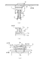
走行路は、半導体を搬送する複数の懸垂型の搬送台車1が走行可能な走行路となっている。これらの走行路は工場の上方(天井側)に設置され、半導体が各搬送台車1に吊り下げられるように搭載されて搬送される。走行路は、平面部材が上下に平行配置され、真中に垂直に平面部材が配設された、断面がエの字型となる形状を有している(図3(b)参照)。尚、ここで半導体とは、例えば、図示しないFOUP(Front Opening Unified Pod)と呼ばれるカセット(収納容器)内に複数枚収納された半導体ウェハである。FOUPは略立方体の形状を有しており、その上面中央にFOUPを把持して搬送するためのフランジが配設されている。半導体は、カセット単位で搬送され、各半導体製造装置105内で所定の処理が施されていく。以下の説明で、搬送台車1によって搬送される搬送物をFOUPと称する。
The travel path is a travel path on which a plurality of suspension-
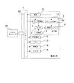
ストッカ104は複数のFOUPが収納可能な保管手段であって、搬送システム100につき1つ又は複数配置されている。FOUPが処理待ちの状態などのときに、FOUPはストッカ104に搬送され、ストッカ104内で要求されるまで保管されるようになっている。また、半導体製造装置105は、工程内軌道108の直下に位置するように配置され、搬送台車1によりFOUPが載置されると、内部に取り込み、クリーンな環境でFOUPに収納されている半導体ウェハに薄膜形成、フォトリソグラフィー、エッチングなどの処理を施す。半導体製造装置105及びストッカ104は、図2に示すシステムコントローラ90と通信可能となっており、システムコントローラ90の指示により各装置が動作するようになっている。
The
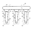
次に、搬送台車1について図3を参照しつつ説明する。搬送台車1は、上述したように、FOUPを把持し走行路を走行し半導体製造装置105及びストッカ104に搬送する。図3(a)に示すように、搬送台車1は、走行機11と、昇降機体12と、ベルト13と、昇降体14と、フィンガ15とを有している。
Next, the
走行機11は、図3(b)及び図3(c)に示すように、支持体11a、支持アーム11b、及び走行体11cを有しており、走行路を一方向(図6中矢印方向)に走行する。走行体11cは、走行路の上下に配設されている平面部材に挟持されて回転する車輪3aを有しており、車輪3aに接続されている回転型のコイルモータ3(発電制動機構・電動機構)(以下、単にモータ3と称す)が駆動することにより、車輪3aが回転し走行路を走行する。また、走行体11cは、走行路の上下に配設されている平面部材に平行するように接触ブレーキ6(ブレーキ機構)が設けられており、搬送システムの異常時には、接触ブレーキ6を走行路に押付けて、その接触摩擦により搬送台車1を停止させるようになっている。走行体11cには、支持アーム11bを介して走行路の下方に位置するように支持体11aが配設されており、支持体11aの下部に昇降機体12が配設されている。
As shown in FIGS. 3B and 3C, the
昇降機体12は、図示しないモータに接続されたリールを有しており、そのリールにベルト13が巻回されている。ベルト13の先端には、昇降体14が配設されており、リールの正逆回転により、ベルト13を介して昇降体14が昇降するようになっている。また、ベルト13は、半導体製造装置105等に載置できるまでFOUPを降下させることができる長さを有している。昇降体14の下部には、フィンガ15が設けられている。フィンガ15は、FOUPのフランジを挟持可能なように開閉可能となっている。上記構成により、搬送台車1は、FOUPを把持して、走行路を走行することができるようになっている。
The
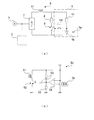
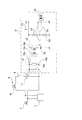
次に、搬送台車1の回路構造及び各機能について図1及び図2を参照しつつ説明する。図2に示すように、搬送台車1は、搬送システム100を制御するシステムコントローラ90と無線又は有線により通信可能なコントローラ80(制御部)を有しており、上述の各機構を動作させるようになっている。また、搬送台車1は、電源70(電源部)を備えており、コントローラ80は、電源70から電力が供給されるようになっている。電源70は、後述のモータ駆動部2及びブレーキ作動部5にも電力を供給するようになっている。尚、図2には示していないが、システムコントローラ90は、半導体製造装置105やストッカ104等にも通信可能となっている。また、電源70は、搬送台車1が備えていなくても良く、搬送台車1の外部から電力が供給されるようになっていても良い。
Next, the circuit structure and functions of the
上記したように、コントローラ80は、走行機11、昇降機体12、ベルト13、昇降体14及びフィンガ15を動作させる。搬送台車1の走行機11は、モータ駆動部2(制御部)と、モータ3と、調節部4と、ブレーキ作動部5(ブレーキ作動機構)と、接触ブレーキ6とを備えている。
As described above, the
モータ駆動部2は、モータ3に制御信号を出力する。また、モータ駆動部2は、電源70に接続されており、電源70の異常時には、制御信号の出力を停止するようになっている。モータ3は、上述したように車輪3aに接続されており、平時は、車輪3aを回転駆動及び停止させることにより走行体11cを走行させる。また、電源70の異常時にモータ駆動部2からの信号が停止すると、惰性により回転する車輪3aと共に回転することで、運動エネルギーを電気エネルギーに変換する発電機として作用するようになっている。さらに、発電機として作用する際に発生する制動力を、車輪3aに付与することでブレーキの役割を果たすようになっている。尚、ここで電気エネルギーとは、電力のことをいう。
The
モータ駆動部2とモータ3とには、ブリッジダイオード7が接続されている。ブリッジダイオード7のアノード側にはコイル61が接続されている。コイル61は、励磁式の接触ブレーキ6を作動させるためのソレノイドである。接触ブレーキ6は、ブレーキシューであり、走行路に押付けることにより搬送台車1にブレーキをかけるようになっている。このコイル61に電流が流れると、接触ブレーキ6が作動し接触摩擦により搬送台車1にブレーキをかけるようになっている。
A
コイル61には調節部4が接続され、自己保持リレー8を介して、ブリッジダイオード7のカソード側に接続されている。自己保持リレー8は、平時は開状態となっており、電源70の異常時には、後述するブレーキ作動部5から出力されるパルス駆動電圧により、閉状態となる。自己保持リレー8は、閉状態となると、パルス駆動電圧が断たれた後も反転への入力があるまで閉状態を保持できるようになっている。
The
自己保持リレー8が閉状態となると、ブリッジダイオード7、コイル61及び調節部4で閉ループを形成する。そして、電源70の異常時に発電機として作用するモータ3からの交流電力がブリッジダイオード7で全波整流され、接触ブレーキ6を作動させるブレーキ電力として閉ループに電力が供給されるようになっている。これにより、コイル61に電流が流れ、接触ブレーキ6が作動するようになっている。また、調節部4は、インダクタンスであり、自己保持リレー8が閉状態となり形成される閉ループ内に流れる電流の大きさを調節する。尚、コイル61及び調節部4を発電機として作用するモータ3の負荷となることで、上述のモータ3による制動力が働くようになっている。
When the self-holding relay 8 is in a closed state, the
ブレーキ作動部5は、調節部4及び自己保持リレー8に並列接続されている。また、ブレーキ作動部5は、電源70に接続されており、電源70が異常の場合、つまり電源70から電力が供給されなくなった場合、パルス駆動電圧を出力して自己保持リレー8を閉状態とするようになっている。これにより、上述した閉ループを形成し、モータ3から閉ループに電力が供給されるようになる。
The
ブレーキ作動部5は、コンデンサ5a、ダイオード5b、インダクタンス5c及びスイッチ回路5dを有している。スイッチ回路5dは、励磁式のスイッチの開閉状態を切替えできる機能を有しており、平時には、スイッチは開状態となっており、電源70の異常時には閉状態となるようになっている。スイッチが閉状態となると、コンデンサ5aに蓄えられている電力で、自己保持リレー8にパルス駆動電圧を出力するようになっている。かかるパルス駆動電圧により、上述したように、自己保持リレー8が閉状態となり、接触ブレーキ6が作動するようになっている。尚、ダイオード5b及びインダクタンス5cは、電流の方向や大きさを調節する周知なものであるため説明は省略する。
The
スイッチ回路5dは、図1(b)に示すように、コイル51、トランジスタ52、インダクタンス53及びコンパレータ54を備えている。コイル51は、エミッタ接地されているトランジスタ52のコレクタに接続されており、プルアップされている。また、トランジスタ52のベースには、ドライブ電力量を調節するインダクタンス53を介してコンパレータ54が接続されている。コンパレータ54の―入力部には、電源70から電力が入力されており、+入力部は、プルアップされている。尚、コンパレータ54の―入力部に入力されている電力は、+入力部と同電位となるように変圧されている。これにより、電源70が正常の場合は、電位差がなく、コンパレータ54は動作しないようになっている。
As shown in FIG. 1B, the
コンパレータ54は、電源70の異常時に電力の供給が停止されると、+入力部の電位が―入力部の電位より高くなるため、差分電圧が出力される。これにより、トランジスタ52のベースに電流が流れ、コレクタ−エミッタ間に電流が流れるようになる。従って、コイル51に電流が流れるようになる。コイル51に電流が流れると、励磁式のスイッチが閉状態となり、コンデンサ5aから自己保持リレー8にパルス駆動電圧を出力するようになっている。これにより、自己保持リレー8は閉状態となる。
When the supply of power is stopped when the
次に、電源70の異常時における搬送装置の動作について説明する。
Next, the operation of the transport device when the
電源70の異常や停電等により、コンパレータ54のー入力部の電位が落ちると、コンパレータ54の電位差が生じるため、コンパレータ54から差分電圧が出力される。それにより、トランジスタ52が動作し、コレクタ−エミッタ間に電流が流れるようになり、コイル51に電流が流れるようになる。それにより、コイル51の励磁式のスイッチが閉状態となる。そうすることにより、コンデンサ5aに蓄えられている電力により、自己保持リレー8にパルス駆動電圧が出力され、自己保持リレー8は閉状態となる。
When the potential at the negative input portion of the
また、一方で、モータ3は電源70の異常や停電等によりモータ駆動部2からの制御信号が停止されると、惰性により回転することで発電機として作用し、発電された電力はブリッジダイオード7により全波整流されたあと、コイル61に供給される。コイル61に電流が流れると、接触ブレーキ6は励磁作動型であるため、接触ブレーキ6が作動し、搬送台車1が接触摩擦によりブレーキがかかる。また、モータ3が発電し、コイル61及び調節部4がモータ3の負荷となることで制動力が発生し、搬送台車1にブレーキがかかる。接触摩擦と制動力との2つのブレーキ作用により搬送台車1が停止する。尚、搬送台車1が停止すると、モータ3は発電しなくなるため、コイル61に電力が供給されず、接触ブレーキ6によるブレーキが解除される。このため、ブレーキ解除機構を設ける必要がなくなる。
On the other hand, when the control signal from the
尚、本実施の形態における搬送台車停止装置は、電源70の異常時に作動するようにしているが、電源70だけでなくモータ駆動部2の異常時にも作動するようにしてもよい。
In addition, although the conveyance trolley | bogie stop apparatus in this Embodiment is made to operate | move when the
以上、説明したように、本実施の形態は、走行路を走行する搬送台車1と、搬送台車1を制御するモータ駆動部2(制御部)と、モータ駆動部2に電力を供給する電源70(電源部)と、走行する搬送台車1を停止させる励磁作動型の接触ブレーキ6(ブレーキ機構)と、電源70および/またはモータ駆動部2の異常時に、搬送台車1の運動エネルギーを電気エネルギーに変換し、それにより搬送台車1に制動力を付与するモータ3(発電制動機構)と、電源70および/またはモータ駆動部2の異常時に、電力(電気エネルギー)をブレーキ電力として接触ブレーキ6に供給することで、接触ブレーキ6を作動させるブレーキ作動機構5とを備えている。
As described above, the present embodiment includes the
上記構成により、停電等の故障による異常時に搬送台車を制御する制御部に電力が供給できない場合に、接触ブレーキ6による接触摩擦とモータ3の制動力とにより、搬送台車を安全に停止させることができる。これにより、走行路に複数台の搬送台車1が走行している場合には、搬送台車1同士が衝突し破損するなどのおそれがなくなる。また、励磁式の接触ブレーキ6を動作し続けるための電気エネルギーをモータ3から得ることができ、省エネルギーを実現することができる。また、搬送台車1が完全に停止すればモータ3は電気エネルギーを生成しなくなるため、搬送台車1が停止すると共に、接触ブレーキ6が解除される。従って、接触ブレーキ6を解除するための機構を設ける必要がなくなる。さらに、接触ブレーキ6は、作動後、モータ3の電気エネルギーで動作し続けるため、ブレーキ作動部5は、接触ブレーキ6を作動させるだけの電力を備えているだけでよくなる。
With the above-described configuration, when power cannot be supplied to the control unit that controls the conveyance carriage in the event of an abnormality due to a failure such as a power failure, the conveyance carriage can be safely stopped by the contact friction by the
尚、コンデンサ5aは、予め充電されているが、電源70の正常時に充電される構成であってもよい。また、自己保持リレー8が閉状態となり形成される閉ループ内の電力の大きさを調節するため調節部4を設けているが、コイル61や、モータ3に用いられるコイル(図示せず)の巻き数を増減させて調節するようにしてもよい。
The
また、自己保持リレー8は、平時が開状態となっており、電源70の異常時に閉状態となるようにしているが、逆であっても良い。つまり、自己保持リレー8を無励磁作動型のリレーを用いて、平時のときは、電源70から電力を供給されることによりリレーを開状態とする。そして、電源70の異常時にはリレーに電力が供給されなくなり、リレーは閉状態となる。これにより、接触ブレーキ6を作動させることができる。
Further, the self-holding relay 8 is in an open state during normal times and is in a closed state when the
(第2の実施形態)
次に、本発明の第2の実施の形態について図4を参照しつつ説明する。本実施の形態は、接触ブレーキ6を作動させるブレーキ作動部5の回路構成が第1の実施形態と相違する。以下、その相違点について説明する。尚、第1の実施形態と同様の部材は、同じ符号を付し、説明は省略する。
(Second Embodiment)
Next, a second embodiment of the present invention will be described with reference to FIG. The present embodiment is different from the first embodiment in the circuit configuration of the
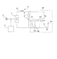
本実施の形態は、第1の実施形態の自己保持リレー8の部分にサイリスタ9を用いている。サイリスタ9のアノード側に調節部4を接続し、カソード側にブリッジダイオード7を接続している。そして、ブレーキ作動部20からサイリスタ9のゲートに電流が供給されると、サイリスタ9がオン状態となり、コイル61に電流が流れ、接触ブレーキ6が作動するようになっている。尚、サイリスタ9は、一度電流が流れ始めると、ゲートに電流が流れなくなってもオン状態を維持するため、ゲートには短パルスを供給するだけでよい。
In the present embodiment, a
ブレーキ作動部20はゲート回路10を備えており、ゲート回路10は、サイリスタ9のゲートに接続されている。ゲート回路10は、上記したように、サイリスタ9をオン/オフ状態を切替える短パルスを供給する。ゲート回路10は、サイリスタ9のノイズによる誤動作を防ぐために、インダクタンス10a・10bおよびコンデンサ10cとを備えたフィルタを構成している。そして、ゲート回路10は、スイッチ回路5dに接続され、さらに、コンデンサ5aおよびダイオード5bが接続されている。尚、コンデンサ5a、ダイオード5bおよびスイッチ回路5dは第1の実施形態と同様のため説明は省略する。
The
次に、電源70の異常時における本実施の形態の搬送装置の動作について説明する。
Next, the operation of the transport device of the present embodiment when the
電源70の異常や停電時には、スイッチ回路5dのスイッチが閉状態となる。それにより、コンデンサ5aに充電されている電力がサイリスタ9のゲートに供給されることにより、サイリスタ9がオン状態となる。それにより、コイル61、ブリッジダイオード7及び調節部4からなる閉ループが形成される。また、一方で、モータ3は電源70の異常や停電等によりモータ駆動部2からの制御信号が停止されると、惰性により回転することで発電機として作用し、発電された電力はブリッジダイオード7により全波整流されたあと、コイル61に供給される。接触ブレーキ6は励磁作動型であるため、コイル61に電流が流れると、接触ブレーキ6が作動し、搬送台車1が接触摩擦によりブレーキがかかる。さらに、コイル61および調節部4を負荷とすることで、モータ3は制動力を発生し、搬送台車1にブレーキがかかる。
When the
以上、説明したように、本実施の形態において第1の実施形態と同様の効果を得ることができる。さらに、ゲート回路10により、ノイズ等によりサイリスタ9が動作することを防ぐことができる。
As described above, in this embodiment, the same effect as that of the first embodiment can be obtained. Further, the
(第3の実施形態)
次に、本発明の第3の実施の形態について図5を参照しつつ説明する。本実施の形態は、接触ブレーキ6を作動させるブレーキ作動部5の回路構成が第1の実施形態と相違する。以下、その相違点について説明する。尚、第1の実施形態と同様の部材は、同じ符号を付し、説明は省略する。
(Third embodiment)
Next, a third embodiment of the present invention will be described with reference to FIG. The present embodiment is different from the first embodiment in the circuit configuration of the
本実施の形態は、第1の実施形態の自己保持リレー8の部分にトライアック11を用いている。また、モータ3は単相2線式となっており、ブリッジダイオード7を省略している。トライアック11は、2つのサイリスタを反対向きに接続し、ゲートを1つにまとめたものである。また、トライアック11は、双方向に電流を流すことができるため、モータ3が単相2線式の場合は、第1の実施形態のブリッジダイオード7を必要としないようになっている。
In the present embodiment, the
トライアック11のゲートにはゲート回路10が接続されており、さらに、絶縁回路12が接続されている。絶縁回路12は、コイル12a・12bを対向配置したリレー回路であり、一方のコイル12aはコイルゲート回路10に接続され、もう一方のコイル12bは、駆動回路13に含まれている。尚、駆動回路13は、第1の実施形態のスイッチ回路5dと同じ構成であり、コイル12bは、コイル51に相当するため、説明は省略する。
A
電源70の異常時には、コイル12bに電流が流れるようになっている。コイル12bに電流が流れると誘導起電力により、コイル12aにも電流が発生するようになっている。従って、ゲート回路10を介してトライアック11のゲートに電流が供給されるようになっている。トライアック11のゲートに電流が供給されると、トライアック11がオン状態となり、モータ3を発電機としてコイル61、調節部4及びトライアック11の閉ループに電流が流れるようになっている。コイル61に電流が流れると接触ブレーキ6が作動し、ブレーキがかかるようになっている。
When the
次に、電源70の異常時における本実施の形態の搬送装置の動作について説明する。
Next, the operation of the transport device of the present embodiment when the
電源70の異常や停電時には、駆動回路13のコイル12bに電流が流れ、磁界が発生する。それに伴い、コイル12aに電流が発生する。それにより、ゲート回路10を介してトライアック11のゲートに電流が供給されることにより、トライアック11がオン状態となる。それにより、コイル61及び調節部4からなる閉ループが形成される。また、一方で、モータ3は電源70の異常や停電等によりモータ駆動部2からの制御信号が停止されると、惰性により回転することで発電機として作用し、発電された電力がコイル61に供給される。接触ブレーキ6は励磁作動型であるため、コイル61に電流が流れると、接触ブレーキ6が作動し、搬送台車1が接触摩擦によりブレーキがかかる。さらに、コイル61および調節部4を負荷とすることで、モータ3は制動力を発生し、搬送台車1にブレーキがかかる。
When the
以上、本実施の形態において、第1及び第2の実施の形態と同様の効果を得ることができる。また、本実施の形態においては、モータ3を2線式とし、トライアック11を用いることで全波整流器のブリッジダイオード7を必要としなくなる。
As described above, in the present embodiment, the same effects as those in the first and second embodiments can be obtained. In the present embodiment, the
また、本発明を好適な実施の形態に基づいて説明したが、本発明はその趣旨を超えない範囲において変更が可能である。例えば、上述の実施の形態では、搬送台車停止装置は半導体製造システムにおいて好適に用いられているが、これに限定されず、別のシステム内に用いられてもよい。また、走行路は上方(天井側)に配設されているが、これに限定されることはない。 Moreover, although this invention was demonstrated based on suitable embodiment, this invention can be changed in the range which does not exceed the meaning. For example, in the above-described embodiment, the transport carriage stop device is suitably used in a semiconductor manufacturing system, but is not limited to this, and may be used in another system. Moreover, although the traveling path is arrange | positioned upwards (ceiling side), it is not limited to this.
本発明は、上記の好ましい実施形態に記載されているが、本発明はそれだけに制限されない。本発明の精神と範囲から逸脱することのない様々な実施形態が他になされることは理解されよう。さらに、本実施形態において、本発明の構成による作用および効果を述べているが、これら作用および効果は、一例であり、本発明を限定するものではない。 Although the present invention has been described in the preferred embodiments above, the present invention is not so limited. It will be understood that various other embodiments may be made without departing from the spirit and scope of the invention. Furthermore, in this embodiment, although the effect | action and effect by the structure of this invention are described, these effect | actions and effects are examples and do not limit this invention.
1 搬送台車
2 モータ駆動部
3 モータ
4 調節部
5 ブレーキ作動部
5a コンデンサ
5d スイッチ回路
6 接触ブレーキ
7 ブリッジダイオード
8 自己保持リレー
70 電源
DESCRIPTION OF
Claims (4)
前記搬送台車を制御する制御部と、
前記制御部に電力を供給する電源部と、
走行する前記搬送台車を停止させる励磁作動型のブレーキ機構と、
前記電源部および/または制御部の異常時に、前記搬送台車の運動エネルギーを電気エネルギーに変換し、それにより前記搬送台車に制動力を付与する発電制動機構と、
前記電源部および/または制御部の異常時に、前記電気エネルギーをブレーキ電力として前記ブレーキ機構に供給することで、前記ブレーキ機構を作動させるブレーキ作動機構と
を備えていることを特徴とする搬送装置。 A transport carriage that travels along the travel path;
A control unit for controlling the transport carriage;
A power supply unit for supplying power to the control unit;
An excitation-actuated brake mechanism for stopping the traveling carriage that travels;
A power generation braking mechanism that converts kinetic energy of the transport carriage into electrical energy and thereby applies a braking force to the transport carriage when the power supply unit and / or the control unit is abnormal;
And a brake operating mechanism that operates the brake mechanism by supplying the electric energy as brake power to the brake mechanism when the power supply unit and / or the control unit is abnormal.
前記電源部及び制御部の正常時には、前記搬送台車を走行させる電動機構であることを特徴とする請求項1に記載の搬送装置。 The dynamic braking mechanism is
The transfer device according to claim 1, wherein the transfer device is an electric mechanism that causes the transfer carriage to travel when the power supply unit and the control unit are normal.
前記走行路との接触摩擦により走行する搬送台車を停止させる
ことを特徴とする請求項1〜3のいずれか1項に記載の搬送装置。
The brake mechanism is
The transport apparatus according to claim 1, wherein the transport cart that travels by contact friction with the travel path is stopped.
Priority Applications (1)
| Application Number | Priority Date | Filing Date | Title |
|---|---|---|---|
| JP2004058703A JP2005250737A (en) | 2004-03-03 | 2004-03-03 | Carrier device |
Applications Claiming Priority (1)
| Application Number | Priority Date | Filing Date | Title |
|---|---|---|---|
| JP2004058703A JP2005250737A (en) | 2004-03-03 | 2004-03-03 | Carrier device |
Publications (1)
| Publication Number | Publication Date |
|---|---|
| JP2005250737A true JP2005250737A (en) | 2005-09-15 |
Family
ID=35031171
Family Applications (1)
| Application Number | Title | Priority Date | Filing Date |
|---|---|---|---|
| JP2004058703A Pending JP2005250737A (en) | 2004-03-03 | 2004-03-03 | Carrier device |
Country Status (1)
| Country | Link |
|---|---|
| JP (1) | JP2005250737A (en) |
Cited By (2)
| Publication number | Priority date | Publication date | Assignee | Title |
|---|---|---|---|---|
| JP2008201268A (en) * | 2007-02-20 | 2008-09-04 | Senyo Kogyo Kk | Braking energy recovery apparatus of track vehicle and transport system |
| JP2016118907A (en) * | 2014-12-19 | 2016-06-30 | 東洋電機製造株式会社 | Automatic driving device |
Citations (8)
| Publication number | Priority date | Publication date | Assignee | Title |
|---|---|---|---|---|
| JPS4971614A (en) * | 1972-11-16 | 1974-07-11 | ||
| JPS5980805U (en) * | 1982-11-19 | 1984-05-31 | 株式会社富士通ゼネラル | Electromagnetic brake control circuit for unmanned vehicles |
| JPH0667835U (en) * | 1993-03-01 | 1994-09-22 | いすゞ自動車株式会社 | Diesel engine start / stop device |
| JPH09233874A (en) * | 1996-02-27 | 1997-09-05 | Sgs Thomson Microelectron Sa | Bidirectional motor on / off control switch |
| JPH11206184A (en) * | 1998-01-19 | 1999-07-30 | Okuma Corp | Inverter control equipment |
| JPH11317655A (en) * | 1997-11-13 | 1999-11-16 | Toshiyasu Suzuki | Insulating type switching means having shielding function, one-way insulating type switching means having shielding function, one-way insulating type three-terminal switching means having shield function, two-way insulating type switching means having shielding function, and two-way insulating type three-terminal switching means having shielding function |
| JP2001001791A (en) * | 1999-04-19 | 2001-01-09 | Toyota Motor Corp | Vehicle control device |
| JP2004023992A (en) * | 2002-06-20 | 2004-01-22 | Max Co Ltd | Braking device of motor |
-
2004
- 2004-03-03 JP JP2004058703A patent/JP2005250737A/en active Pending
Patent Citations (8)
| Publication number | Priority date | Publication date | Assignee | Title |
|---|---|---|---|---|
| JPS4971614A (en) * | 1972-11-16 | 1974-07-11 | ||
| JPS5980805U (en) * | 1982-11-19 | 1984-05-31 | 株式会社富士通ゼネラル | Electromagnetic brake control circuit for unmanned vehicles |
| JPH0667835U (en) * | 1993-03-01 | 1994-09-22 | いすゞ自動車株式会社 | Diesel engine start / stop device |
| JPH09233874A (en) * | 1996-02-27 | 1997-09-05 | Sgs Thomson Microelectron Sa | Bidirectional motor on / off control switch |
| JPH11317655A (en) * | 1997-11-13 | 1999-11-16 | Toshiyasu Suzuki | Insulating type switching means having shielding function, one-way insulating type switching means having shielding function, one-way insulating type three-terminal switching means having shield function, two-way insulating type switching means having shielding function, and two-way insulating type three-terminal switching means having shielding function |
| JPH11206184A (en) * | 1998-01-19 | 1999-07-30 | Okuma Corp | Inverter control equipment |
| JP2001001791A (en) * | 1999-04-19 | 2001-01-09 | Toyota Motor Corp | Vehicle control device |
| JP2004023992A (en) * | 2002-06-20 | 2004-01-22 | Max Co Ltd | Braking device of motor |
Cited By (2)
| Publication number | Priority date | Publication date | Assignee | Title |
|---|---|---|---|---|
| JP2008201268A (en) * | 2007-02-20 | 2008-09-04 | Senyo Kogyo Kk | Braking energy recovery apparatus of track vehicle and transport system |
| JP2016118907A (en) * | 2014-12-19 | 2016-06-30 | 東洋電機製造株式会社 | Automatic driving device |
Similar Documents
| Publication | Publication Date | Title |
|---|---|---|
| KR102575953B1 (en) | Magnetic levitation transfer apparatus | |
| WO2003038869A2 (en) | Universal modular wafer transport system | |
| JP7322120B2 (en) | Transfer device | |
| TWI899317B (en) | Article transport facility | |
| JP2005250737A (en) | Carrier device | |
| TW202525686A (en) | Transport vehicle | |
| KR20220097701A (en) | Article transport facility | |
| JP2004334724A (en) | Operation control device, program and method | |
| JP5617868B2 (en) | Transport device | |
| WO2024122138A1 (en) | Transport vehicle system | |
| US12227110B2 (en) | Track-guided cart system | |
| JP7783567B2 (en) | Transport vehicle | |
| KR102785002B1 (en) | Article transport facility and article transport method | |
| JP3216778B2 (en) | Transfer equipment using linear motor | |
| JP2006103879A (en) | Carriage | |
| TW202300425A (en) | Hash overhead hoist transport rail system and methods of operating the same | |
| KR102324406B1 (en) | Transferring unit and article transferring apparatus comprising the same | |
| CN115593953B (en) | Article conveying vehicle and article conveying apparatus | |
| JP4321222B2 (en) | Magnetic suction ceiling suspension carriage | |
| KR102763762B1 (en) | Transfer apparatus and method of controlling the same | |
| US11749548B2 (en) | Transport system, associated movable container and method | |
| KR20250101500A (en) | Driving wheel for electronic brake using eddy current and transport vehicle including the same | |
| KR102343620B1 (en) | Apparatus for transporting carrier and system for transporting carrier with the apparatus | |
| KR20230100551A (en) | Article transport facility | |
| KR20250118773A (en) | Transport facility |
Legal Events
| Date | Code | Title | Description |
|---|---|---|---|
| A621 | Written request for application examination |
Free format text: JAPANESE INTERMEDIATE CODE: A621 Effective date: 20060831 |
|
| A621 | Written request for application examination |
Free format text: JAPANESE INTERMEDIATE CODE: A621 Effective date: 20060831 |
|
| A131 | Notification of reasons for refusal |
Free format text: JAPANESE INTERMEDIATE CODE: A131 Effective date: 20090224 |
|
| A521 | Request for written amendment filed |
Free format text: JAPANESE INTERMEDIATE CODE: A523 Effective date: 20090422 |
|
| A131 | Notification of reasons for refusal |
Free format text: JAPANESE INTERMEDIATE CODE: A131 Effective date: 20090908 |
|
| A711 | Notification of change in applicant |
Free format text: JAPANESE INTERMEDIATE CODE: A711 Effective date: 20091023 |
|
| A521 | Request for written amendment filed |
Free format text: JAPANESE INTERMEDIATE CODE: A821 Effective date: 20091117 |
|
| RD02 | Notification of acceptance of power of attorney |
Free format text: JAPANESE INTERMEDIATE CODE: A7422 Effective date: 20091117 |
|
| A521 | Request for written amendment filed |
Free format text: JAPANESE INTERMEDIATE CODE: A523 Effective date: 20100106 |
|
| A02 | Decision of refusal |
Free format text: JAPANESE INTERMEDIATE CODE: A02 Effective date: 20100202 |