JP2005249256A - Hollow fiber membrane type humidifier - Google Patents
Hollow fiber membrane type humidifier Download PDFInfo
- Publication number
- JP2005249256A JP2005249256A JP2004058432A JP2004058432A JP2005249256A JP 2005249256 A JP2005249256 A JP 2005249256A JP 2004058432 A JP2004058432 A JP 2004058432A JP 2004058432 A JP2004058432 A JP 2004058432A JP 2005249256 A JP2005249256 A JP 2005249256A
- Authority
- JP
- Japan
- Prior art keywords
- hollow fiber
- water
- membrane
- air
- dirt
- Prior art date
- Legal status (The legal status is an assumption and is not a legal conclusion. Google has not performed a legal analysis and makes no representation as to the accuracy of the status listed.)
- Pending
Links
Images


Abstract
Description
本発明は、空調、住宅、家電、燃料電池などの分野において、加湿に使用される中空糸膜式加湿器の中空糸の洗浄に関する。 The present invention relates to cleaning of hollow fibers of a hollow fiber membrane humidifier used for humidification in the fields of air conditioning, housing, home appliances, fuel cells, and the like.
近年、健康、清潔指向の高まりの中で住空間をより快適にする要求が高まっている。室内の環境条件の中で、温度については高度な機能と省エネ性を兼ね備えたエアコンが登場し、ほぼ要求を達成した状況であるが、湿度についていえばエアコンには通常加湿機能が無く、特に冬場などの乾燥期にエアコンを使用すると相対湿度が下がって乾燥がさらにすすみ、喉や目の痛み、手肌の乾燥などを訴えるケースが増えてきている。また約50%以上の湿度でウイルスの活性が低下することが知られるようになり加湿の重要性の認識が高まってきている。このような中で、加湿器に対する要求もますます高まっており、低コスト、小型、省エネ、低騒音、低消費電力といった基本性能の向上だけでなく、抗菌、殺菌機能があるものや、マイナスイオンを付加するタイプ、アレルギーやウイルスを除去するフィルターを備えたタイプなど多種多様な付加機能を有するものが登場している。ここで、従来の加湿器に用いられている加湿方式としては大きく分けると気化式、スチームファン式、超音波式がよく知られているが、各方式に一長一短があり、現在のところ消費者の全ての要求を満足できる加湿方式は登場していない。中でも超音波加湿器は、低騒音、低消費電力と大きな加湿力を備え、一時期爆発的に普及したが、水タンク中に発生した雑菌を水滴と共に飛散させる恐れがあること、水滴中の金属イオンが水の蒸発と共に白い粉末となって析出するいわゆる白粉問題が発生したため市場から姿を消し、現在では、雑菌や白粉の発生がない気化式が主流となっている。気化式加湿器は水を含んだフィルターに空気を接触させ、空気中から蒸発潜熱を奪って水を気化するのであるが、この方式の場合、加湿効率を向上するためには圧力損失をできるだけ小さくしつつ水と空気の接触面積を増加させることが必要である。一方、近年、水の透過性を備えた多孔性膜の性能の向上が目覚しく、気化式加湿器のフィルターとして多孔性膜が利用されるようになってきた。特に最近では燃料電池に用いられる加湿器として多孔性膜を中空円筒状に形成した中空糸を束ね、中空糸の内外に乾燥空気と水や湿潤空気を流して加湿する中空糸膜式加湿器が、加湿効率が非常に高い気化式加湿器として採用されてきており、さらに中空糸膜式加湿器を家庭用の加湿器へ応用する取り組みも行われている。 In recent years, there has been an increasing demand for more comfortable living spaces amid growing health and cleanliness. Air conditioners with advanced functions and energy-saving performance have appeared in the indoor environmental conditions, and the situation is almost met, but in terms of humidity, air conditioners usually have no humidification function, especially in winter. When air conditioners are used during the dry season, the relative humidity drops and the drying progresses further, and there are an increasing number of cases complaining of sore throat and eye pain and dry hand skin. In addition, it has been known that virus activity decreases at a humidity of about 50% or more, and recognition of the importance of humidification is increasing. Under these circumstances, the demand for humidifiers is increasing, and not only improvements in basic performance such as low cost, small size, energy saving, low noise, and low power consumption, but also antibacterial and sterilizing functions, and negative ions There are various types that have a variety of additional functions, such as a type that adds a filter and a type that has a filter that removes allergies and viruses. Here, vaporizing, steam fan, and ultrasonic methods are well known as humidifying methods used in conventional humidifiers, but each method has its merits and demerits. There is no humidification method that can satisfy all requirements. Ultrasonic humidifiers, among others, have low noise, low power consumption, and high humidification power, and have spread explosively for some time. However, there is a risk that various germs generated in the water tank may be scattered along with the water droplets, and metal ions in the water droplets. However, the so-called white powder problem that occurs as white powder precipitates as the water evaporates has disappeared from the market. At present, the vaporization type is free of germs and white powder. Vaporizing humidifiers bring water into contact with a filter containing water and take the latent heat of vaporization from the air to vaporize the water. In this method, the pressure loss is minimized as much as possible to improve the humidification efficiency. However, it is necessary to increase the contact area between water and air. On the other hand, in recent years, the performance of porous membranes having water permeability has been remarkably improved, and porous membranes have been used as filters for vaporizing humidifiers. In particular, as a humidifier used in fuel cells, there is a hollow fiber membrane humidifier that bundles hollow fibers in which a porous membrane is formed into a hollow cylindrical shape and humidifies by flowing dry air, water, or humid air inside and outside the hollow fibers. In addition, it has been adopted as a vaporizing humidifier with very high humidifying efficiency, and an effort is also being made to apply a hollow fiber membrane humidifier to a home humidifier.
以下、その中空糸膜式加湿器について図を参照しながら説明する。 Hereinafter, the hollow fiber membrane humidifier will be described with reference to the drawings.
図12は従来の中空糸膜式加湿器の加湿モジュール101を示している。図において加湿モジュール101は多数本の所定長さの中空糸102を平行に、かつ円筒状に収束して収束物となし、個々の中空糸102の両端部が開口した状態で固定部103に円筒状に固定され、両端の固定部103がそれぞれ水流入口104を備えた水供給部105、水流出口106を備えた水排出部107に挿入され固定されたものである。このような構成の加湿モジュール101において水を水流入口104から供給すると、水は中空糸102の開口端からその内部へと拡散する。そして中空糸102内部の水は水蒸気となって中空糸102の内側から外側に移動し、中空糸102の外表面の微細孔から滲出される。そして残余の水は水排出部107に集水され、水流出口106から排水される。この時、加湿モジュール101の側方から空気を圧送してやれば、中空糸102表面の水蒸気が空気中に移行し、空気を加湿することができる。
しかしながら、このような従来の中空糸膜式加湿器では、加湿水として一般の水道水を使用した場合、水中の固形物等が中空糸の表面および微細孔に付着して目詰まりが生じ加湿性能が低下するという課題があり、水道水を使用しても長期にわたり加湿性能を維持できる中空糸膜式加湿器が要求されている。 However, in such a conventional hollow fiber membrane type humidifier, when ordinary tap water is used as the humidifying water, the solid matter in the water adheres to the surface of the hollow fiber and the micropores, resulting in clogging and humidifying performance. Therefore, there is a demand for a hollow fiber membrane humidifier that can maintain humidification performance over a long period of time even when tap water is used.
また、水道水の場合は水中の電解質が中空糸表面の気液接触面にスケールとして析出し中空糸の表面および微細孔に付着して目詰まりが生じ加湿性能が低下するという課題があり、水道水を使用してもスケールが付着せず長期にわたり加湿性能を維持できる中空糸膜式加湿器が要求されている。 Also, in the case of tap water, there is a problem that the electrolyte in the water deposits as a scale on the gas-liquid contact surface of the hollow fiber surface and adheres to the surface and fine pores of the hollow fiber, resulting in clogging and reducing the humidification performance. There is a need for a hollow fiber membrane humidifier that can maintain humidification performance over a long period of time without using scale even when water is used.
また、加湿運転をした場合、水道水に添加されいる塩素は直ちに空気中に飛散してしまい殺菌力が無くなり、加湿モジュール内部の水中に微生物が繁殖しやすく、多量の微生物が中空糸の表面および微細孔に付着してバイオフィルムを形成し中空糸の目詰まりが生じ加湿性能が低下するという課題があり、バイオフィルムが付着せず長期にわたり加湿性能を維持できる中空糸膜式加湿器が要求されている。 In addition, when humidifying operation is performed, chlorine added to tap water is immediately scattered in the air, sterilizing power is lost, microorganisms easily propagate in the water inside the humidifying module, and a large amount of microorganisms are on the surface of the hollow fiber and There is a problem that the biofilm is formed by adhering to the micropores, resulting in clogging of the hollow fiber, resulting in a decrease in the humidification performance. ing.
本発明は、このような従来の課題を解決するものであり、水道水を使用しても長期にわたり加湿性能を維持できる中空糸膜式加湿器を提供することを目的としている。 This invention solves such a conventional subject, and it aims at providing the hollow fiber membrane type humidifier which can maintain humidification performance over a long term, even if it uses tap water.
本発明の中空糸膜式加湿器は上記目的を達成するために、水分を透過する微細孔を有する膜を円筒状に形成した中空糸を複数本束ね、前記中空糸の内外の一方に気体を他方に水を流し、膜を透過した水が気体に接触し水分を供給することにより加湿する構成の中空糸膜式加湿器において、中空糸表面に付着した膜汚れを除去する膜汚れ除去手段を備えるとしたものである。 In order to achieve the above object, the hollow fiber membrane humidifier of the present invention bundles a plurality of hollow fibers formed in a cylindrical shape with a membrane having fine pores that allow moisture to pass through, and gas is supplied to one of the inside and outside of the hollow fiber. On the other hand, in the hollow fiber membrane humidifier configured to humidify by flowing water and allowing the water that has passed through the membrane to contact the gas and supply moisture, membrane dirt removing means for removing the membrane dirt adhered to the hollow fiber surface is provided. It is meant to be prepared.
これにより、水道水を使用しても長期にわたり加湿性能を維持できる中空糸膜式加湿器が得られる。 Thereby, even if it uses tap water, the hollow fiber membrane type humidifier which can maintain humidification performance over a long term is obtained.
また、他の手段は、空気を送風する送風手段と水を送水する送水手段を備え、水分を透過する微細孔を有する膜を円筒状に形成した中空糸を複数本束ね、これを水流入口及び水流出口を備えたケーシング内に収納し、前記ケーシングの両端部において前記中空糸の内側と外側が連通しないように複数の前記中空糸の間を封止し前記中空糸の一端を空気流入口、他端を空気流出口とし、前記空気流入口から空気を、前記水流入口からは水を流すことにより、前記中空糸膜の外側から透過した水が前記中空糸の内周面に接触する気体に水分を供給することにより加湿する構成の中空糸膜式加湿器において、前記中空糸の表面に付着した膜汚れを除去する膜汚れ除去手段を備えるとしたものである。 In addition, the other means includes a blowing means for blowing air and a water feeding means for feeding water, and bundles a plurality of hollow fibers in which a membrane having a fine hole that allows moisture to pass through is formed into a cylindrical shape. It is housed in a casing having a water outlet, sealed between a plurality of the hollow fibers so that the inside and outside of the hollow fiber do not communicate with each other at both ends of the casing, and one end of the hollow fiber is an air inlet, The other end is an air outlet, and air is allowed to flow from the air inlet and water is allowed to flow from the water inlet, so that the water that has permeated from the outside of the hollow fiber membrane becomes a gas that contacts the inner peripheral surface of the hollow fiber. The hollow fiber membrane humidifier configured to humidify by supplying moisture is provided with a membrane dirt removing means for removing membrane dirt adhered to the surface of the hollow fiber.
これにより、水道水を使用しても長期にわたり加湿性能を維持できる中空糸膜式加湿器が得られる。 Thereby, even if it uses tap water, the hollow fiber membrane type humidifier which can maintain humidification performance over a long term is obtained.
また他の手段は、膜汚れ除去手段として、膜汚れを中空糸から分離して除去する膜汚れ分離手段を備えるとしたものである。 The other means is provided with a membrane dirt separating means for separating and removing the membrane dirt from the hollow fiber as the membrane dirt removing means.
これにより、水道水を使用しても長期にわたり加湿性能を維持できる中空糸膜式加湿器が得られる。 Thereby, even if it uses tap water, the hollow fiber membrane type humidifier which can maintain humidification performance over a long term is obtained.
また他の手段は、膜汚れ分離手段として、水流により膜汚れを除去するとしたものである。 The other means is a means for removing membrane dirt by a water stream as membrane dirt separating means.
これにより、水道水を使用しても長期にわたり加湿性能を維持できる中空糸膜式加湿器が得られる。 Thereby, even if it uses tap water, the hollow fiber membrane type humidifier which can maintain humidification performance over a long term is obtained.
また他の手段は、膜汚れ分離手段として、中空糸の空気側に水を流し膜汚れを除去するとしたものである。 Another means is a means for removing membrane dirt by flowing water to the air side of the hollow fiber as membrane dirt separating means.
これにより、水道水を使用しても長期にわたり加湿性能を維持できる中空糸膜式加湿器が得られる。 Thereby, even if it uses tap water, the hollow fiber membrane type humidifier which can maintain humidification performance over a long term is obtained.
また他の手段は、膜汚れ分離手段として、中空糸の空気側、水側双方に水を流し膜汚れを除去するとしたものである。 Another means is to remove the membrane dirt by flowing water to both the air side and the water side of the hollow fiber as the membrane dirt separating means.
これにより、水道水を使用しても長期にわたり加湿性能を維持できる中空糸膜式加湿器が得られる。 Thereby, even if it uses tap water, the hollow fiber membrane type humidifier which can maintain humidification performance over a long term is obtained.
また他の手段は、膜汚れ分離手段として、中空糸の空気側の流れを塞ぐ空気流閉鎖手段を備え、前記中空糸の空気側から水を流し、水を逆流させて水側から出すとしたものである。 The other means is provided with air flow closing means for blocking the air-side flow of the hollow fiber as the membrane dirt separation means, and water is flowed from the air side of the hollow fiber, and the water is made to flow backward and out from the water side. Is.
これにより、水道水を使用しても長期にわたり加湿性能を維持できる中空糸膜式加湿器が得られる。 Thereby, even if it uses tap water, the hollow fiber membrane type humidifier which can maintain humidification performance over a long term is obtained.
また他の手段は、膜汚れ分離手段として、水流入口からケーシング内部を流れる水の流速を断続的に変化させるとしたものである。 Another means is a means for intermittently changing the flow rate of water flowing from the water inlet to the inside of the casing as a membrane dirt separating means.
これにより、水道水を使用しても長期にわたり加湿性能を維持できる中空糸膜式加湿器が得られる。 Thereby, even if it uses tap water, the hollow fiber membrane type humidifier which can maintain humidification performance over a long term is obtained.
また他の手段は、膜汚れ分離手段として、ケーシング内部の水に気泡を発生させる気泡発生手段を備え、気泡が膜汚れを分離するとしたものである。 The other means includes a bubble generating means for generating bubbles in the water inside the casing as the membrane dirt separating means, and the bubbles separate the membrane dirt.
これにより、水道水を使用しても長期にわたり加湿性能を維持できる中空糸膜式加湿器が得られる。 Thereby, even if it uses tap water, the hollow fiber membrane type humidifier which can maintain humidification performance over a long term is obtained.
また他の手段は、気泡発生手段として、空気流出口を塞ぐ空気流出口閉鎖手段を備え、送風手段により空気流入口へ空気を送風し中空糸の水側へ空気を送りこんで気泡を発生させるとしたものである。 The other means includes, as the bubble generating means, an air outlet closing means that closes the air outlet, and blows air to the air inlet by the blowing means and sends air to the water side of the hollow fiber to generate bubbles. It is a thing.
これにより、水道水を使用しても長期にわたり加湿性能を維持できる中空糸膜式加湿器が得られる。 Thereby, even if it uses tap water, the hollow fiber membrane type humidifier which can maintain humidification performance over a long term is obtained.
また他の手段は、気泡発生手段として、水流入口の上流側に気泡発生部を備え、送風手段から空気を気泡発生部に送りこむとしたものである。 In addition, as another means for generating bubbles, a bubble generating section is provided on the upstream side of the water inlet, and air is sent from the blowing means to the bubble generating section.
これにより、水道水を使用しても長期にわたり加湿性能を維持できる中空糸膜式加湿器が得られる。 Thereby, even if it uses tap water, the hollow fiber membrane type humidifier which can maintain humidification performance over a long term is obtained.
また他の手段は、膜汚れ除去手段として、中空糸または及び水に振動を与えて膜汚れを分離する振動発生手段を備えるとしたものである。 The other means is provided with a vibration generating means for applying vibration to the hollow fiber or water to separate the film dirt as the film dirt removing means.
これにより、水道水を使用しても長期にわたり加湿性能を維持できる中空糸膜式加湿器が得られる。 Thereby, even if it uses tap water, the hollow fiber membrane type humidifier which can maintain humidification performance over a long term is obtained.
また他の手段は、振動発生手段として、複数の中空糸を束ねた中空糸束が回転またはおよび振動するとしたものである。 Another means is that a hollow fiber bundle in which a plurality of hollow fibers are bundled is rotated or vibrated as vibration generating means.
これにより、水道水を使用しても長期にわたり加湿性能を維持できる中空糸膜式加湿器が得られる。 Thereby, even if it uses tap water, the hollow fiber membrane type humidifier which can maintain humidification performance over a long term is obtained.
また他の手段は、振動発生手段として、ケーシング内部の水に超音波振動を与える超音波振動子を備えるとしたものである。 Another means is provided with an ultrasonic vibrator for applying ultrasonic vibration to the water inside the casing as the vibration generating means.
これにより、水道水を使用しても長期にわたり加湿性能を維持できる中空糸膜式加湿器が得られる。 Thereby, even if it uses tap water, the hollow fiber membrane type humidifier which can maintain humidification performance over a long term is obtained.
また他の手段は、膜汚れ除去手段として、膜汚れを分解して除去する膜汚れ分解手段を備えるとしたものである。 The other means is provided with a film dirt removing means for decomposing and removing the film dirt as the film dirt removing means.
これにより、水道水を使用しても長期にわたり加湿性能を維持できる中空糸膜式加湿器が得られる。 Thereby, even if it uses tap water, the hollow fiber membrane type humidifier which can maintain humidification performance over a long term is obtained.
また他の手段は、膜汚れ分解手段として、有機成分を分解する波長を持った紫外線を中空糸に照射するとしたものである。 Another means is to irradiate the hollow fiber with ultraviolet rays having a wavelength for decomposing organic components as a means for decomposing the membrane dirt.
これにより、水道水を使用しても長期にわたり加湿性能を維持できる中空糸膜式加湿器が得られる。 Thereby, even if it uses tap water, the hollow fiber membrane type humidifier which can maintain humidification performance over a long term is obtained.
また他の手段は、膜汚れ分解手段として、中空糸表面に光触媒を塗布し、光触媒を活性化させる紫外線を中空糸に照射するとしたものである。 Another means is to apply a photocatalyst to the surface of the hollow fiber and irradiate the hollow fiber with ultraviolet rays that activate the photocatalyst as a means for decomposing the membrane dirt.
これにより、水道水を使用しても長期にわたり加湿性能を維持できる中空糸膜式加湿器が得られる。 Thereby, even if it uses tap water, the hollow fiber membrane type humidifier which can maintain humidification performance over a long term is obtained.
また他の手段は、紫外光源がLEDであるとしたものである。 Another means is that the ultraviolet light source is an LED.
これにより、水道水を使用しても長期にわたり加湿性能を維持できる中空糸膜式加湿器が得られる。 Thereby, even if it uses tap water, the hollow fiber membrane type humidifier which can maintain humidification performance over a long term is obtained.
また他の手段は、膜汚れ分解手段として、中空糸に酸性水を流す酸性水発生手段を備えるとしたものである。 Another means is provided with an acidic water generating means for flowing acidic water through the hollow fiber as the membrane dirt decomposing means.
これにより、水道水を使用しても長期にわたり加湿性能を維持できる中空糸膜式加湿器が得られる。 Thereby, even if it uses tap water, the hollow fiber membrane type humidifier which can maintain humidification performance over a long term is obtained.
また他の手段は、酸性水発生手段として、電解水発生装置を備えるとしたものである。 Another means includes an electrolyzed water generator as the acidic water generator.
これにより、水道水を使用しても長期にわたり加湿性能を維持できる中空糸膜式加湿器が得られる。 Thereby, even if it uses tap water, the hollow fiber membrane type humidifier which can maintain humidification performance over a long term is obtained.
また他の手段は、膜汚れ分解手段として、水流入口からケーシング内部を流れる水の温度を上げ下げして膜汚れの溶解度を上げるとしたものである。 The other means is a means for decomposing membrane dirt, which raises and lowers the temperature of the water flowing from the water inlet to the inside of the casing to increase the solubility of the membrane dirt.
これにより、水道水を使用しても長期にわたり加湿性能を維持できる中空糸膜式加湿器が得られる。 Thereby, even if it uses tap water, the hollow fiber membrane type humidifier which can maintain humidification performance over a long term is obtained.
さらに他の手段は、膜汚れの除去を行う時、中空糸の空気側、水側双方とも水を通水した状態で処理を行うとしたものである。 Still another means is that when removing the membrane dirt, the treatment is performed in a state where water is passed through both the air side and the water side of the hollow fiber.
これにより、水道水を使用しても長期にわたり加湿性能を維持できる中空糸膜式加湿器が得られる。 Thereby, even if it uses tap water, the hollow fiber membrane type humidifier which can maintain humidification performance over a long term is obtained.
本発明によれば、長期にわたり加湿性能を維持できる効果のある中空糸膜式加湿器を提供できる。 ADVANTAGE OF THE INVENTION According to this invention, the hollow fiber membrane type humidifier which has the effect which can maintain humidification performance over a long term can be provided.
本発明の請求項1記載の発明は、水分を透過する微細孔を有する膜を円筒状に形成した中空糸を複数本束ね、前記中空糸の内外の一方に気体を他方に水を流し、膜を透過した水が気体に接触し水分を供給することにより加湿する構成の中空糸膜式加湿器において、中空糸表面に付着した膜汚れを除去する膜汚れ除去手段を備えるとしたものであり、中空糸表面や微細孔に付着した汚れを除去するという作用を有する。 According to the first aspect of the present invention, a plurality of hollow fibers formed in a cylindrical shape with a membrane having fine pores that allow moisture to pass through are bundled, gas is flowed to one of the inside and outside of the hollow fiber, and water is flowed to the other. In the hollow fiber membrane humidifier configured to humidify the water that has passed through the gas in contact with the gas and supplying moisture, the membrane dirt removal means for removing the membrane dirt attached to the hollow fiber surface is provided. It has the effect of removing dirt adhering to the hollow fiber surface and micropores.
また、空気を送風する送風手段と水を送水する送水手段を備え、水分を透過する微細孔を有する膜を円筒状に形成した中空糸を複数本束ね、これを水流入口及び水流出口を備えたケーシング内に収納し、前記ケーシングの両端部において前記中空糸の内側と外側が連通しないように複数の前記中空糸の間を封止し前記中空糸の一端を空気流入口、他端を空気流出口とし、前記空気流入口から空気を、前記水流入口からは水を流すことにより、前記中空糸膜の外側から透過した水が前記中空糸の内周面に接触する気体に水分を供給することにより加湿する構成の中空糸膜式加湿器において、前記中空糸の表面に付着した膜汚れを除去する膜汚れ除去手段を備えるとしたものであり、中空糸表面や微細孔に付着した汚れを除去する作用を有する。 In addition, it is provided with a blowing means for blowing air and a water feeding means for feeding water, and bundles a plurality of hollow fibers formed in a cylindrical shape having a fine hole through which moisture permeates, and has a water inlet and a water outlet. The hollow fibers are housed in a casing and sealed between the hollow fibers so that the inner and outer sides of the hollow fibers do not communicate with each other at both ends of the casing. By supplying air from the air inlet and water from the water inlet, water that has permeated from the outside of the hollow fiber membrane supplies moisture to a gas that contacts the inner peripheral surface of the hollow fiber. In the hollow fiber membrane humidifier configured to humidify by means of the above, it is provided with a membrane dirt removing means for removing the membrane dirt adhered to the surface of the hollow fiber, and removes dirt adhered to the hollow fiber surface and fine pores. Have the effect of
また、膜汚れ除去手段として、膜汚れを中空糸から分離して除去する膜汚れ分離手段を備えるとしたものであり、中空糸や微細孔に付着した汚れを中空糸表面から分離する作用を有する。 Further, as the membrane dirt removing means, it is provided with a membrane dirt separating means for separating and removing the membrane dirt from the hollow fiber, and has an action of separating the dirt adhering to the hollow fiber and the fine hole from the surface of the hollow fiber. .
また、膜汚れ分離手段として、水流により膜汚れを除去するとしたものであり、中空糸に接触する水の流れが中空糸や微細孔に付着した汚れを水中に分離しケーシング外部へ排出する作用を有する。 Also, as a membrane dirt separation means, the membrane dirt is removed by water flow, and the flow of water in contact with the hollow fiber separates the dirt adhering to the hollow fiber and micropores into the water and discharges it outside the casing. Have.
また、膜汚れ分離手段として、中空糸の空気側に水を流し膜汚れを除去するとしたものであり、空気流入口から水を流すことにより中空糸の空気側面に付着した汚れを水中に分離しケーシング外部へ排出する作用を有する。 In addition, as a means for separating membrane dirt, water is flowed to the air side of the hollow fiber to remove the membrane dirt, and the dirt adhering to the air side surface of the hollow fiber is separated into water by flowing water from the air inlet. Has the effect of discharging to the outside of the casing.
また、膜汚れ分離手段として、中空糸の空気側、水側双方に水を流し膜汚れを除去するとしたものであり、中空糸内外に水が流れることにより中空糸内外に付着した膜汚れを同時に分離するという作用を有する。 In addition, as a membrane dirt separation means, water is flowed to both the air side and the water side of the hollow fiber to remove the membrane dirt. At the same time, the membrane dirt adhering to the inside and outside of the hollow fiber due to water flowing inside and outside the hollow fiber is removed. Has the effect of separating.
また、膜汚れ分離手段として、中空糸の空気側の流れを塞ぐ空気流閉鎖手段を備え、前記中空糸の空気側から水を流し、水を逆流させて水側から出すとしたものであり、空気流出口が塞がっていることにより、空気流入口から入った水は中空糸の微細孔を逆流し水側へと流れ、この時、微細孔に堆積した汚れは水流により水側へと押し流されケーシング外部へ排出するという作用を有する。 Further, as the membrane dirt separation means, it is provided with an air flow closing means for closing the flow of the hollow fiber on the air side, and water is flowed from the air side of the hollow fiber, and the water is made to flow backward and out from the water side, Due to the blockage of the air outlet, the water entering from the air inlet flows back to the water side through the microholes of the hollow fiber, and at this time, the dirt accumulated in the micropores is pushed to the water side by the water flow. It has the effect of discharging to the outside of the casing.
また、膜汚れ分離手段として、水流入口からケーシング内部を流れる水の流速を断続的に変化させるとしたものであり、水の流速を断続的に変化させることにより中空糸に付着した汚れの分離を促進するという作用を有する。 Further, as a membrane dirt separation means, the flow rate of water flowing from the water inlet to the inside of the casing is changed intermittently, and the dirt attached to the hollow fiber is separated by changing the water flow rate intermittently. Has the effect of promoting.
また、膜汚れ分離手段として、ケーシング内部の水に気泡を発生させる気泡発生手段を備え、気泡が膜汚れを分離するとしたものであり、水中に発生した気泡が中空糸の壁面に沿って流れ、汚れに衝突して分離するという作用を有する。 Further, as the membrane dirt separating means, it is provided with a bubble generating means for generating bubbles in the water inside the casing, and the bubbles are to separate the membrane dirt, and the bubbles generated in the water flow along the wall surface of the hollow fiber, It has an effect of separating by colliding with dirt.
また、気泡発生手段として、空気流出口を塞ぐ空気流出口閉鎖手段を備え、送風手段により空気流入口へ空気を送風し中空糸の水側へ空気を送りこんで気泡を発生させるとしたものであり、空気流出口を塞いで空気流入口から空気の圧力をることにより、中空糸の微細孔より気泡を多量に発生させるという作用を有する。 Further, as the bubble generating means, an air outlet closing means for closing the air outlet is provided, and air is blown to the air inlet by the blowing means and air is sent to the water side of the hollow fiber to generate bubbles. The air flow outlet is closed and air pressure is applied from the air flow inlet, thereby generating a large amount of bubbles from the micropores of the hollow fiber.
また、気泡発生手段として、水流入口の上流側に気泡発生部を備え、送風手段から空気を気泡発生部に送りこむとしたものであり、気泡発生部から発生した気泡が中空糸表面に付着した汚れを分離するという作用を有する。 Further, as the bubble generating means, a bubble generating part is provided upstream of the water inlet, and air is sent from the blowing means to the bubble generating part, and the bubbles generated from the bubble generating part are adhered to the surface of the hollow fiber. It has the effect | action of isolate | separating.
また、膜汚れ除去手段として、中空糸または及び水に振動を与えて膜汚れを分離する振動発生手段を備えるとしたものであり、中空糸または及び水が振動することにより中空糸表面に付着した汚れを分離するという作用を有する。 Further, as the membrane dirt removing means, there is provided a vibration generating means for separating the membrane dirt by applying vibration to the hollow fiber or water, and attached to the hollow fiber surface due to vibration of the hollow fiber or water. It has the effect of separating dirt.
また、振動発生手段として、複数の中空糸を束ねた中空糸束が回転またはおよび振動するとしたものであり、中空糸束が回転または及び振動し、遠心力や慣性力により汚れを分離するという作用を有する。 Further, as the vibration generating means, a hollow fiber bundle in which a plurality of hollow fibers are bundled is rotated or vibrated, and the hollow fiber bundle is rotated or vibrated to separate dirt by centrifugal force or inertial force. Have
また、振動発生手段として、ケーシング内部の水に超音波振動を与える超音波振動子を備えるとしたものであり、ケーシング内部の水に超音波振動を付加することにより水中にキャビテーションを生じさせ、キャビテーションにより生じた空隙が破裂する時の衝撃力により中空糸に付着した汚れを分離するという作用を有する。 Further, as the vibration generating means, an ultrasonic vibrator for applying ultrasonic vibration to the water inside the casing is provided, and cavitation is generated in the water by adding ultrasonic vibration to the water inside the casing, thereby causing cavitation. It has the effect | action of isolate | separating the stain | pollution | contamination adhering to a hollow fiber with the impact force at the time of the space | gap produced by explosion.
また、膜汚れ除去手段として、膜汚れを分解して除去する膜汚れ分解手段を備えるとしたものであり、中空糸に付着した汚れを分解して水中に溶かすことにより加湿性能が回復するという作用を有する。 Further, as the membrane dirt removing means, it is provided with a membrane dirt decomposing means for decomposing and removing the membrane dirt, and the humidifying performance is restored by decomposing the dirt adhering to the hollow fiber and dissolving it in water. Have
また、膜汚れ分解手段として、有機成分を分解する波長を持った紫外線を中空糸に照射するとしたものであり、紫外線により中空糸の表面に付着した有機物を分解するという作用を有する。 Further, the membrane dirt is decomposed by irradiating the hollow fiber with ultraviolet rays having a wavelength for decomposing organic components, and has an action of decomposing organic substances adhering to the surface of the hollow fiber by the ultraviolet rays.
また、膜汚れ分解手段として、中空糸表面に光触媒を塗布し、光触媒を活性化させる紫外線を中空糸に照射するとしたものであり、紫外線により中空糸表面に塗布された光触媒が活性化され表面にOHラジカルが発生し、ラジカルの酸化力により中空糸の表面に付着した汚れを酸化分解するという作用を有する。 In addition, as a means for decomposing membrane dirt, a photocatalyst is applied to the surface of the hollow fiber and the hollow fiber is irradiated with ultraviolet rays that activate the photocatalyst. OH radicals are generated, and have the effect of oxidizing and decomposing dirt attached to the surface of the hollow fiber by the oxidizing power of the radicals.
また、紫外光源がLEDであるとしたものであり、紫外線源にLEDを使用することにより中空糸束の深部にまで紫外線を到達させるという作用を有する。 Further, the ultraviolet light source is assumed to be an LED, and by using the LED as the ultraviolet light source, the ultraviolet light reaches the deep part of the hollow fiber bundle.
また、膜汚れ分解手段として、中空糸に酸性水を流す酸性水発生手段を備えるとしたものであり、酸性水を流すことにより中空糸表面に付着した炭酸カルシウム等の酸溶解性スケールを分解するという作用を有する。 In addition, as a means for decomposing membrane dirt, an acid water generating means for flowing acidic water to the hollow fiber is provided, and an acid-soluble scale such as calcium carbonate attached to the hollow fiber surface is decomposed by flowing the acidic water. It has the action.
また、酸性水発生手段として、電解水発生装置を備えるとしたものであり、水に直流電圧を印加して電気分解することにより酸性水を得るという作用を有する。 In addition, as the acidic water generating means, an electrolyzed water generating device is provided, and has an action of obtaining acidic water by applying a direct current voltage to water and performing electrolysis.
また、膜汚れ分解手段として、水流入口からケーシング内部を流れる水の温度を上げ下げして膜汚れの溶解度を上げるとしたものであり、水温の上げ下げにより温度によって溶解度が変化する性質の膜汚れを溶解するという作用を有する。 In addition, as a means for decomposing membrane dirt, the temperature of the water flowing inside the casing from the water inlet is raised and lowered to increase the solubility of the film dirt, and the degree of solubility of the film varies depending on the temperature by raising and lowering the water temperature. Has the effect of
また、膜汚れの除去を行う時、中空糸の空気側、水側双方とも水を通水した状態で処理を行うとしたものであり、中空糸全体を水中に没した状態で膜汚れ去手段を行うことにより水に接触する面積が増え、空気側面に付着した汚れをも除去するという作用を有する。 Also, when removing the membrane dirt, the treatment is performed with water flowing through both the air side and the water side of the hollow fiber, and the membrane dirt removing means is immersed in the whole hollow fiber. As a result, the area in contact with water is increased, and the dirt attached to the air side surface is also removed.
以下、本発明の実施の形態について図面を参照しながら説明する。 Hereinafter, embodiments of the present invention will be described with reference to the drawings.
(実施の形態1)
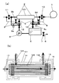
従来例と同一の部分については同一番号を付し、詳細な説明は省略する。図1に示すように、本発明の中空糸膜式加湿器は、被加湿空気を吸入し加湿された空気を外部に送風するための送風手段としての送風機1と、空気を送風するための送風経路2と送風機1により送られてきた空気を加湿するための加湿モジュール101と、加湿モジュール101に水を循環させるための加湿水循環経路3と加湿水循環経路3内の水を循環させるための送水手段としてのポンプ4と、加湿水循環系路3上で加湿水を貯留するためのタンク5と、タンク5の水を系外に排出するための排水口6と排水を制御する排水弁7を備えている。また、送風経路2は加湿モジュール101の前後で加湿水循環経路3と接続する気水連絡経路8を2本ずつ備えており、気水連絡経路8には開閉により経路を遮断する気水連絡経路弁9a、9b、9c、9dが配置されている。さらに送風経路2、加湿水循環経路3上の、2本の気水連絡経路8の分岐点の間には送風前弁10、送風後弁11、送水前弁12、送水後弁13が配置されている。
(Embodiment 1)
The same parts as those in the conventional example are denoted by the same reference numerals, and detailed description thereof is omitted. As shown in FIG. 1, the hollow fiber membrane humidifier of the present invention includes a
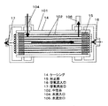
また、加湿モジュール101は図2に示すように水の透過性を有する多孔性膜を管状に形成した中空糸102を複数本束ね、略円筒形状のケーシング14内に収納し、その両端部において、中空糸102の内側と外側が連通しないように複数の中空糸の間をエポキシなどの樹脂によりなる封止部15により封止してある。ケーシング14には中空糸102の内側の流路に空気を供給するための空気流入口16、中空糸102内部の流路から空気を排出するための空気流出口17、中空糸102の外側でケーシング14の内側に水を供給するための水流入口104、中空糸102の外側でケーシング14の内側を流通してきた水を加湿モジュール101の外部へと排出するための水流出口106が設けられている。
Further, as shown in FIG. 2, the
次に、本発明の中空糸膜式加湿器が通常の加湿運転を行う場合の動作を説明する。図1に示ように通常の加湿時においては、送風前弁10、送風後弁11、送水前弁12、送水後弁13を開に、全ての気水連絡経路弁9を閉にする。ここで加湿水循環経路3上のタンク5からポンプ4により送水された加湿用水は加湿モジュール101の水流入口104より加湿モジュール101内の中空糸102の外側、ケーシング14の内側の流路へと供給される。加湿水は加湿モジュール101内で水の透過性をもつ中空糸102の内側の流路を通る空気と熱交換及び水蒸気の移行を行って低温となった後、水流出口106を経て水流出口106に接続された加湿水循環経路3へと排出される。加湿水循環経路3に排出された加湿後の残余水は再びタンク5へと戻される。一方、送風機1により送風された被加湿空気は送風経路2を通って空気流入口16から加湿モジュール101内へと送り込まれ、中空糸102の内部で中空糸102の外側から透過してきた水分と接触して加湿され空気流出口17より送風経路2を通って送風される。
Next, the operation when the hollow fiber membrane humidifier of the present invention performs a normal humidification operation will be described. As shown in FIG. 1, during normal humidification, the
尚、本実施の形態において、空気の流れを太字の点線、加湿水の流れを太い実線、流れのない経路を細い実線、弁は図1の送風後弁11に示すように開状態で白抜き、排水弁7に示すように閉状態では黒塗りで表示してある。
In the present embodiment, the air flow is indicated by bold dotted lines, the humidified water flow is indicated by a thick solid line, the non-flow path is indicated by a thin solid line, and the valve is open and white as shown in FIG. In the closed state, as shown in the
ここで、加湿器を連続的に長期間運転した場合、加湿モジュール101内の中空糸102の表面には水中の汚れ成分、いわゆる膜汚れが付着し、水分が中空糸102の膜を透過する割合である水透過率が低下し加湿性能が次第に低下してくる。膜汚れは大きく分けると、水中の微粒子、スケール、バイオフィルムに大別でき、膜汚れが微細孔の深部に堆積したり表面に付着して膜の微細孔を閉塞したりして水透過率が減少する。膜汚れのうち微粒子は水に溶解していない固形成分で中空糸102表面に電気的、化学的に吸着する。また、スケールは中空糸102における膜内部および表面の気液界面において、蒸発による水分の減少により水中の電解質成分が局所的に溶解度を越えて濃縮され、空気中の二酸化炭素等と結合して難溶性の塩として析出してくるものである。特に微細孔内部に析出したスケールを放置しておくと微細な結晶粒を形成しながら徐々に成長し非常に強力に膜表面に固着し、容易に除去することができなくなる。また、加湿モジュール101内部には、加湿水中や送風機1から送り込まれる空気に乗って微生物が侵入してくるが、加湿モジュール101内部の水に微生物が大量に繁殖した場合、微生物は膜表面や微細孔内部に付着し、微生物の死骸や粘ちょう性の代謝物を伴いながらバイオフィルム、いわゆるスライムを形成して中空糸102の水透過率を大幅に低下させる恐れがある。
Here, when the humidifier is operated continuously for a long period of time, a dirt component in water, so-called membrane dirt adheres to the surface of the
ここで、本実施の形態は、膜汚れ除去手段として定期的に、中空糸102内部に付着した膜汚れを水流により膜表面から分離することにより、水透過率を回復させ、長期間にわたり加湿性能を維持する膜汚れ分離手段を備えるとしたものである。以下、加湿モジュールの内部の中空糸に付着した膜汚れ分離手段について具体的に説明する。
Here, the present embodiment periodically recovers the water permeability by separating the membrane dirt adhered inside the
図3は本実施の形態の中空糸膜式加湿器において中空糸102の空気側に水を流すことにより膜汚れを分離する例を示している。図3の(a)において送風機1を停止し、送風前弁10、送風後弁11、送水前弁12、送水後弁13、気水連絡経路弁9b、9dを閉じ、気水連絡経路弁9aと9cを開くことにより、ポンプ4から送水された水が加湿モジュール101の中空糸102の空気側を通りタンク5に戻る。この時、図3の(b)に示すようにに、中空糸102の内側の空気の経路に水が流れ、水流により空気の経路の表面に付着した膜汚れを膜表面より分離し水流に乗せてタンク5まで押し流すことができる。タンク5には汚れが排出されてくるので排水弁7を開き系外へ汚れを排出する。
FIG. 3 shows an example of separating membrane dirt by flowing water to the air side of the
同様に、図4は本実施の形態の別の例として図3で説明した状態で送水前弁12、送水後弁13を開いた場合であり、中空糸102の内外両面に水を流すことにより膜の内外両方の表面に付着した膜汚れを同時に除去することができる。
Similarly, FIG. 4 shows a case where the
図5はさらに別の例を示す。図5(a)では空気流閉鎖手段としての送風前弁10、送風後弁11、送水前弁12、気水連絡経路弁9b、9c及び9dを閉じ、気水連絡経路弁9aと送風後弁11を開くことにより、ポンプ4から送出された加湿水は加湿モジュール101の空気流出口17より流入するが、空気流入口16の出口が塞がっていることにより、図5(b)に示すように中空糸102の内側から外側へ向かって圧力がかかり、膜表面の微細孔から加湿水が中空糸102の外側へと透過して流れ、水流出口106からタンク5へと回収される。この時、加湿水の流れ方向は通常の加湿時における水の透過方向と逆方向に進行しいわゆる逆洗状態となり、微細孔の内部に堆積した膜汚れは膜表面から分離され中空糸の外側へ押し戻され水流に乗って加湿モジュール101の外部へ排出される。
FIG. 5 shows another example. In FIG. 5 (a), the
以上のように、加湿モジュール101の空気流出口17から水を送出することにより中空糸102表面に付着した膜汚れを水流を用いて膜表面から分離させ、加湿モジュール101の外部へ排出することにより、中空糸102の水透過率を回復させ加湿性能の低下を防ぐことができる。
As described above, by sending water from the
この時、ポンプ4を断続的に動作させたり、水が流れる経路の途中にある弁を断続的に開閉させることにより、水流に脈動を生じさせ、流速を一時的に増減することにより、水流による膜汚れの分離作用をさらに促進することができる。
At this time, the
また、本発明の実施の形態では上述の3つのパターン全てが可能なように、構成したが、このうちの1つあるいは、2つの組み合わせだけで処理を行う場合、構成はさらに簡略化できる。 In the embodiment of the present invention, the above-described three patterns are configured to be possible. However, when processing is performed with only one or a combination of the two, the configuration can be further simplified.
また、上記の3つのパターンを組み合わせて用いることも可能であり、この場合、膜汚れの除去効果はさらに高められる。 It is also possible to use a combination of the above three patterns. In this case, the effect of removing the film dirt is further enhanced.
(実施の形態2)
実施の形態1と同一の部分については同一番号を付し、詳細な説明は省略する。
(Embodiment 2)
The same parts as those in the first embodiment are denoted by the same reference numerals, and detailed description thereof is omitted.
本実施の形態は、膜汚れ分離手段として気泡発生手段を備え、気泡発生手段により水流に気泡を発生させ、気泡により中空糸102内部に付着した膜汚れを膜表面から分離することにより、水透過率を回復させ長期間にわたり加湿性能を維持するとしたものである。以下、加湿モジュール101の内部の気泡発生手段を説明する。
This embodiment includes a bubble generating means as a membrane dirt separating means, generating bubbles in the water flow by the bubble generating means, and separating the membrane dirt adhered inside the
図6は加湿モジュール101内部の水に気泡を発生させる気泡発生手段の一例を示している。図6(a)に示すように、送風前弁10、送水前弁12、送水後弁13を開き、空気流閉鎖手段としての送風後弁11および全ての気水連絡経路弁9を閉じることにより、送風機1から送出された空気は加湿モジュール101の空気流入口16より流入するが、空気流出口17の出口側が塞がっていることにより、図6(b)に示すように中空糸102の内側から外側へ向かって空気の圧力がかかり、膜表面の微細孔から空気が中空糸の外側へと透過して流れ、大量の微細な気泡が発生し膜表明を流れることにより膜表面に付着した膜汚れを分離し、膜汚れは水流に乗って水流出口106からタンク5へと排出される。この時、気泡は膜の空気側から発生し、膜の微細孔内部に付着した膜汚れをも除去することができる。また、気泡はタンク5により大気へと開放される。
FIG. 6 shows an example of bubble generating means for generating bubbles in the water inside the
尚、本実施の形態において、空気の流れを太字の点線、加湿水の流れを太い実線、流れのない経路を細い実線、弁は開状態で白抜き、閉状態では黒塗りで表示してあり、特に加湿モジュールから送水経路を通ってタンクへと排水される気泡を含んだ気液混相流は太字の破線で示している。 In this embodiment, the air flow is indicated by a bold dotted line, the humidified water flow is indicated by a thick solid line, the non-flow path is indicated by a thin solid line, the valve is open and white, and the closed state is black. In particular, the gas-liquid mixed phase flow including bubbles discharged from the humidification module through the water supply path to the tank is indicated by a bold broken line.
また、図7は気泡発生手段の別の例を示しており、図7の(a)は本実施の形態の中空糸式加湿器の構成を示しており、送風経路2は加湿モジュール101の前で加湿水循環経路3に備えられた気泡発生手段としての気泡発生部18と接続する気泡発生部連絡経路19を備えており、気泡発生部連絡経路19には開閉により経路を遮断する気泡発生部連絡経路弁20が配置されている。
7 shows another example of the bubble generating means, FIG. 7A shows the configuration of the hollow fiber humidifier of the present embodiment, and the
また、加湿モジュール101には図7(b)に示すように水流入口104の上流側に気泡発生部連絡経路19と接続した気泡発生部18が接続されており、気泡発生部18はエアーストーン等多孔質の素材で形成されている。
Further, as shown in FIG. 7B, the
ここで、気泡発生路連絡経路弁20を開き、送風前弁10を閉じることにより、送風機1から送出された空気は気泡発生部連絡経路19より気泡発生部18へと送りこまれる。このとき空気は気泡発生部18の微細孔より水流入口104から送水されている水へと微細な気泡となって送り込まれ、加湿モジュール101内部を流れる水に大量の微細な気泡が発生し、気泡は中空糸102の膜表面を流れることにより付着した膜汚れに衝突して中空糸より分離し、膜汚れは水流に乗って水流出口106からタンク5へと排出される。
Here, by opening the bubble generation path
尚、本実施の形態において気泡発生手段について二つの例を用いて説明したが、加湿モジュール101の内部を流れる水流に気泡を発生する手段であれば、例えば電気分解による水素発生などの方法を用いても同様の効果が期待できる。
In the present embodiment, the bubble generating means has been described by using two examples. However, as long as it is a means for generating bubbles in the water flow flowing inside the
(実施の形態3)
実施の形態1と同一の部分については同一番号を付し、詳細な説明は省略する。
(Embodiment 3)
The same parts as those in the first embodiment are denoted by the same reference numerals, and detailed description thereof is omitted.
本実施の形態は、膜汚れ分離手段として振動発生手段を備え、振動発生手段により加湿モジュール内の水または及び中空糸102に振動を発生させることにより中空糸102内部に付着した膜汚れを膜表面から分離することにより、水透過率を回復させ長期間にわたり加湿性能を維持するとしたものである。以下、加湿モジュール101の内部の振動発生手段を説明する。
This embodiment includes a vibration generating means as a membrane dirt separating means, and the vibration generating means causes the water in the humidification module or the membrane dirt attached to the inside of the
図8は本実施の形態の加湿モジュール101を示している。(a)において、加湿モジュール101内部の中空糸102を束ねた中空糸束21は中空糸102及び封止部15と一体に形成されており、中空糸束21はケーシング14内部において水密を維持しながら長軸方向に回転自在なように配置されている。また、中空糸束21の側面一端には円筒棒状の軸22が接続され、軸22は空気流入口16を通ってモーター23に接続されている。(b)は中空糸束21の斜視図を示している。ここで、モーター23に電力を投入して中空糸束21を回転させると、中空糸102の膜表面に付着した膜汚れは遠心力により水中へと分離し、水流により加湿モジュール101の外部へ排出することにより、中空糸102の水透過率を回復させ加湿性能の低下を防ぐことができる。
FIG. 8 shows the
尚、本実施の形態において、加湿水の流れを太い実線で表示してある。 In addition, in this Embodiment, the flow of humidification water is displayed with the thick continuous line.
尚、本実施の形態では、中空糸束21を回転する手段として、軸22を加湿モジュール101の外部に出し、モーター23によって回転させる方法を示したが、中空糸102を回転するのであれば、別の手段、例えば中空糸102に磁石を貼り付け、外部より磁場を与えて回転させる方法や、中空糸束21の外部を流れる水流を円周方向に与えて回転させる方法等も考えられ、同様の効果が期待できる。
In the present embodiment, as a means for rotating the
尚、本実施の形態では、中空糸束21を回転し、遠心力により膜汚れを分離する方法で説明したが、モーター23の代りに中空糸束21を直接振動させる振動発生手段を使用し、中空糸の往復振動により膜汚れを分離しても同様の効果が期待できる。
In the present embodiment, the
また、図9は振動発生手段としてケーシング14に超音波振動子24を設置した例である。超音波振動子24は超音波発振回路25に接続されており、超音波発振回路25は電源装置(図示せず)に接続されている。ここで超音波振動子24によりケーシング14内面と中空糸102外面と間の空間を流れる水に数十〜数百Hzの超音波振動を印加した場合、水中に超音波による疎密が発生し疎の状態で圧力の減少により気泡が発生し、気泡が消滅する際には気泡の周囲の水が衝突し強い衝撃波を発生する。これはキャビテーション現象と呼ばれており、キャビテーションにより生じた衝撃波が膜表面に付着している膜汚れを破砕して水中へと分離し加湿モジュール101の外部へ排出することにより、中空糸膜の水透過率を回復させ加湿性能の低下を防ぐことができる。
FIG. 9 shows an example in which an
(実施の形態4)
実施の形態1と同一の部分については同一番号を付し、詳細な説明は省略する。
(Embodiment 4)
The same parts as those in the first embodiment are denoted by the same reference numerals, and detailed description thereof is omitted.
図10は本実施の形態の加湿モジュールを示している。図10において、中空糸102の表面は膜汚れ除去手段としての膜汚れ分解手段として酸化チタンを主成分とした光触媒が塗布されている。また、ケーシング14内面には約380nm以下の波長を有した広角紫外LED26が備えられている。また、中空糸102と中空糸102の間の空間には同様の波長を有した狭角紫外LED27が配置されている。各LEDは外部に設置された電源(図示せず)と配線(図示せず)により接続されている。光触媒は光活性効果を有する酸化チタンを主成分としている。酸化チタンはn型半導体に属し約390nm以下波長の電磁波が照射されると酸化チタンを構成している価電子が励起され正孔と伝導帯電子が生じ、酸化チタンと接触している水と酸素を酸化還元して水酸化物ラジカル(・OH)や過酸化水素を発生させ、これらの強力な酸化力により有機物を分解する。ここで、本実施の形態においては、LEDを用いて紫外線を照射し、光触媒の分解作用により中空糸102の表面に付着したバイオフィルム等の有機物による膜汚れを分解して水中に溶解させ、加湿モジュール101の外部へ排出することにより、中空糸102の水透過率を回復させ加湿性能の低下を防ぐことができる。
FIG. 10 shows the humidification module of the present embodiment. In FIG. 10, the surface of the
尚、本実施の形態において、加湿水の流れを太い実線で表示してある。 In addition, in this Embodiment, the flow of humidification water is displayed with the thick continuous line.
ところで、光触媒の分解作用が持続する為には連続的に紫外線を照射しなければならない。紫外線源としては真空中に水銀を封入したランプ(ブラックライト)を用いてもよいが、ブラックライトは消費電力が大きいうえサイズが大きく、外側の中空糸102を照射するのが限界であり、深部にある中空糸102に紫外線を照射することが困難である。そこで本実施の形態においては、紫外線を放射する光源としてLEDを使用している。LEDは低消費電力かつ小型であり、中空糸102と中空糸102の間の空間に複数個設置可能である。本実施の形態においては、低距離広範囲に照射できる広角紫外LED26と長距離狭範囲に照射できる狭角紫外LED27を併用しており、ケーシング14内面に設置されたLEDは広角タイプで外周の中空糸102を広範囲に渡り照射する。一方狭角タイプは、中空糸102と中空糸102の間に設置し、中空糸102の軸方向に紫外線を照射することができる。
By the way, in order to continue the decomposition action of the photocatalyst, it is necessary to continuously irradiate ultraviolet rays. A lamp (black light) in which mercury is enclosed in a vacuum may be used as the ultraviolet light source. However, the black light has a large power consumption and a large size, and the limit is that the outer
以上のように、中空糸102内部にLEDを複数個組み合わせて設置することにより、中空糸102の全体に紫外線を照射することができ、中空糸102表面の光触媒の活性を維持することができる。
As described above, by installing a combination of a plurality of LEDs inside the
尚、本実施の形態におけるLEDの配置はほんの一例であり、中空糸102のサイズや形状、LEDの種類形状により様々な配置が考えられ、本実施の形態で説明した配置に限定されるものではない。
The LED arrangement in the present embodiment is merely an example, and various arrangements are conceivable depending on the size and shape of the
尚、中空糸102は有機系高分子が用いられる事が多く、光触媒は有機物を分解する作用があるので、中空糸102の表面に塗布する場合、無機系の下地剤で処理し、膜を保護することが必要である。また、本実施の形態において光触媒の皮膜を形成する場合、膜表面の微細孔を塞がないように処理してある。
The
また、本実施の形態では膜汚れ分解手段として光触媒の酸化作用により有機物を分解するが、光触媒を用いず紫外線単独の殺菌、有機物分解作用を用いることもできる。この場合、紫外線は殺菌線253.7nmや有機物分解作用のある185nmと短い波長の紫外線を用いる。現在のところこのような短い波長のLEDは実用化されていないので、光源としてLEDを用いることはできず、低圧水銀ランプを用いることになるが、将来的にLEDが実用化された場合は本実施の形態のように配置することも可能となる。 In the present embodiment, the organic matter is decomposed by the oxidation action of the photocatalyst as the film dirt decomposition means, but it is also possible to use ultraviolet light sterilization or organic substance decomposition action without using the photocatalyst. In this case, ultraviolet rays having a short wavelength such as a germicidal line of 253.7 nm and an organic substance decomposing action of 185 nm are used. At present, such short-wavelength LEDs have not been put into practical use, so LEDs cannot be used as a light source, and low-pressure mercury lamps will be used. It is also possible to arrange as in the embodiment.
(実施の形態5)
実施の形態1と同一の部分については同一番号を付し、詳細な説明は省略する。
(Embodiment 5)
The same parts as those in the first embodiment are denoted by the same reference numerals, and detailed description thereof is omitted.
本実施の形態の中空糸膜式加湿器は、図11の(a)に示すように、加湿モジュール101とタンク5を繋ぐ加湿水循環経路3から電解水経路28が分岐され、電解水経路28は膜汚れ分解手段としての酸性水発生手段としての電解水発生装置29に接続されている。電解水発生装置29からは酸性水供給管30およびアルカリ性水供給管31がそれぞれタンク5と排水口6に接続されている。また、加湿モジュール101とタンク5を繋ぐ加湿水循環経路3のタンク5との接続点より前段側には送水後弁13が、電解水経路28には電解水弁32がそれぞれ接続されている。ここで、送風機1を停止し電解水弁32を開き、送水後弁13を閉じることにより、ポンプ4から送り込まれた加湿水は加湿モジュール101を出た後、電解水経路28を通って電解水発生装置29へと送り込まれる。
In the hollow fiber membrane humidifier of the present embodiment, as shown in FIG. 11A, the electrolyzed
図11の(b)は二層式の電解水発生装置29を模式的に表した図であり、電解槽33内部に直流電源34に接続された陽極35と陰極36が隔膜としてのイオン交換膜37を隔てて配置されている。水道水等電解質を含んだ水に直流電圧を印加すると、陽極35側では水が分解されて酸素と水素イオンが発生すると共に水中の塩素イオンが結合して塩素が発生し、陰極36側では水が分解されて水素と水酸化物イオンが発生する。この時、陽極35側で発生した塩素が水に溶けて次亜塩素酸となり陽極35側の水は酸性を示す。反対に陰極36側の水はアルカリ性を示す。電解水発生装置29を通電した状態でポンプ4を連続運転した場合、電解水発生装置29から酸性水が酸性水供給管30を通ってタンク5に回収され、加湿モジュール101を流れる加湿水は酸性となり、陰極36側のアルカリ性水はアルカリ性水供給管31を通って排出される。
FIG. 11B schematically shows a two-layer type electrolyzed
尚、本実施の形態において、空気の流れを太字の点線、加湿水の流れを太い実線、流れのない経路を細い実線、弁は開状態で白抜き、閉状態では黒塗りで表示してある。 In the present embodiment, the air flow is indicated by bold dotted lines, the humidified water flow is indicated by a thick solid line, the non-flow path is indicated by a thin solid line, the valve is open and white, and the closed state is black. .
このように、加湿モジュール101内部に酸性の水を流すことにより中空糸102の膜に付着した炭酸カルシウムや炭酸マグネシウムなど酸溶解性のスケールが溶解されると共に、次亜塩素酸の酸化力により微生物やバイオフィルムなどの有機物を殺菌、分解することができ、分解した膜汚れは水流に乗ってタンク5へと回収される。このようにして中空糸102の水透過率を回復させ加湿性能の低下を防ぐことができる。
In this way, by flowing acidic water inside the
ここで、水の電気分解は通常水道水を用いる。この場合pHは3.5程度が限度であるが、別途塩化ナトリウムなどの電解質を投入することによりpHを2.7以下の強酸性にすることも可能であり、膜汚れの除去効果をさらに高めることができる。 Here, water electrolysis usually uses tap water. In this case, the pH is limited to about 3.5, but it is also possible to make the pH strongly 2.7 or less by adding an electrolyte such as sodium chloride separately, which further enhances the effect of removing membrane dirt. be able to.
また、本実施の形態では、アルカリ性水を排水して用いていないが、構成を逆にして酸性水を捨て、アルカリ性水を流すことによりアルカリ溶解性の膜汚れの分解に用いてもよい。さらに、これらを組み合わせて用いることも可能である。 In this embodiment, alkaline water is not drained and used. However, the configuration may be reversed and the acidic water may be discarded and the alkaline water may be used to decompose the alkali-soluble film stain. Furthermore, it is also possible to use these in combination.
尚、本実施の形態では、電解により次亜塩素酸による酸性水を作製したが、水のpHを下げるのであれば電解以外の方法であっても同様の効果が期待できる。 In the present embodiment, acidic water using hypochlorous acid is produced by electrolysis, but the same effect can be expected even by a method other than electrolysis if the pH of the water is lowered.
また、本実施の形態においては膜汚れ溶解手段として酸性水を用いたが、膜汚れを分解する手段として、水温を一定時間上下させる方法も考えられる。水温を上げた場合は高温で溶解度が増すシリカ系のスケールやバイオフィルムを溶解することができ、水温を下げた場合は、炭酸塩系の低温で溶解度が増すスケールを溶解することができる。対象となる膜汚れに対し選択して用いるとよい。 Further, in this embodiment, acidic water is used as the film dirt dissolving means, but as a means for decomposing the film dirt, a method of raising and lowering the water temperature for a certain time is also conceivable. When the water temperature is raised, a silica-based scale or biofilm whose solubility is increased at a high temperature can be dissolved, and when the water temperature is lowered, a carbonate-based scale whose solubility is increased at a low temperature can be dissolved. It is good to select and use for the target film | membrane dirt.
これまで、説明した実施の形態1、2、3、4、5を用いることにより、膜汚れを除去し中空糸102の水透過率を回復させ加湿性能の低下を防ぐことができるが、各実施の形態において、基本的には中空糸102の外部に水を通水し、内側については実施の形態1を除き特に言及しなかったが、中空糸102の内側の空気の経路に水を流し中空糸内外に通水した状態で処理を行うことによりさらに一層膜汚れの分離、分解効果が促進される。
By using the first, second, third, fourth, and fifth embodiments described so far, it is possible to remove membrane dirt and recover the water permeability of the
さらに本発明の実施の形態では、加湿モジュール101の中空糸102の内側に空気を流し、外側に水を流して加湿する構成で説明したが、水と空気を逆にした配置の構成とした加湿器においても本発明の各本実施の形態を適用可能である。
Furthermore, in the embodiment of the present invention, the description has been given of the configuration in which air is flowed inside the
本発明にかかる中空糸膜式加湿器は、長期にわたり加湿性能を維持できる効果を有し、加湿、空調、燃料電池の用途にも適用できる。 The hollow fiber membrane humidifier according to the present invention has an effect of maintaining humidification performance over a long period of time, and can be applied to humidification, air conditioning, and fuel cell applications.
1 送風機
2 送風経路
3 加湿水循環経路
4 ポンプ
5 タンク
8 気水連絡経路
9 気水連絡経路弁
10 送風前弁
11 送風後弁
12 送水前弁
13 送水後弁
14 ケーシング
15 封止部
16 空気流入口
17 空気流出口
18 気泡発生部
19 気泡発生部連絡経路
20 気泡発生部連絡経路弁
21 中空糸束
23 モーター
24 超音波振動子
26 広角紫外LED
27 狭角紫外LED
29 電解水発生装置
101 加湿モジュール
102 中空糸
104 水流入口
106 水流出口
DESCRIPTION OF
27 Narrow UV LED
29
Claims (22)
Priority Applications (1)
| Application Number | Priority Date | Filing Date | Title |
|---|---|---|---|
| JP2004058432A JP2005249256A (en) | 2004-03-03 | 2004-03-03 | Hollow fiber membrane type humidifier |
Applications Claiming Priority (1)
| Application Number | Priority Date | Filing Date | Title |
|---|---|---|---|
| JP2004058432A JP2005249256A (en) | 2004-03-03 | 2004-03-03 | Hollow fiber membrane type humidifier |
Publications (1)
| Publication Number | Publication Date |
|---|---|
| JP2005249256A true JP2005249256A (en) | 2005-09-15 |
Family
ID=35029892
Family Applications (1)
| Application Number | Title | Priority Date | Filing Date |
|---|---|---|---|
| JP2004058432A Pending JP2005249256A (en) | 2004-03-03 | 2004-03-03 | Hollow fiber membrane type humidifier |
Country Status (1)
| Country | Link |
|---|---|
| JP (1) | JP2005249256A (en) |
Cited By (12)
| Publication number | Priority date | Publication date | Assignee | Title |
|---|---|---|---|---|
| JP2007195875A (en) * | 2006-01-30 | 2007-08-09 | Sanyo Electric Co Ltd | Air disinfection device |
| WO2007125707A1 (en) * | 2006-04-26 | 2007-11-08 | Entegris, Inc. | Liquid vaporization apparatus |
| KR100911563B1 (en) * | 2007-08-29 | 2009-08-10 | 현대자동차주식회사 | Humidifier for fuel cell vehicle |
| CN102607126A (en) * | 2012-03-23 | 2012-07-25 | 魏宝利 | External pressure hollow fiber membrane humidifier |
| JP2014001899A (en) * | 2012-06-19 | 2014-01-09 | Mitsubishi Electric Corp | Water treatment device, humidifier and hot water dispensing system |
| KR101449154B1 (en) | 2012-12-05 | 2014-10-08 | 현대자동차주식회사 | Ultrasonic humidifier apparatus for membrane humidifier |
| WO2014192887A1 (en) * | 2013-05-29 | 2014-12-04 | 久光製薬株式会社 | System for producing microneedle pharmaceutical preparation, and air-conditioning method |
| CN106765746A (en) * | 2016-11-28 | 2017-05-31 | 西安工程大学 | Film dehumidifying dew point indirect evaporative cooling air conditioning group based on Driven by Solar Energy |
| CN113418257A (en) * | 2020-02-20 | 2021-09-21 | 成都中邦智能科技有限责任公司 | A evaporation filter core mounting structure for vertical evaporation humidifier |
| US11130148B2 (en) | 2013-05-29 | 2021-09-28 | Hisamitsu Pharmaceutical Co., Inc. | System for manufacturing microneedle preparation, and air-conditioning method |
| CN113932394A (en) * | 2020-06-29 | 2022-01-14 | 中国移动通信集团浙江有限公司 | Antiscaling method and equipment for wet film humidifier |
| KR20220169101A (en) * | 2021-06-18 | 2022-12-27 | (주)필로스 | Hollow fiber membrane dehumidifier and humidity control device having the same |
-
2004
- 2004-03-03 JP JP2004058432A patent/JP2005249256A/en active Pending
Cited By (17)
| Publication number | Priority date | Publication date | Assignee | Title |
|---|---|---|---|---|
| JP2007195875A (en) * | 2006-01-30 | 2007-08-09 | Sanyo Electric Co Ltd | Air disinfection device |
| WO2007125707A1 (en) * | 2006-04-26 | 2007-11-08 | Entegris, Inc. | Liquid vaporization apparatus |
| KR100911563B1 (en) * | 2007-08-29 | 2009-08-10 | 현대자동차주식회사 | Humidifier for fuel cell vehicle |
| CN102607126A (en) * | 2012-03-23 | 2012-07-25 | 魏宝利 | External pressure hollow fiber membrane humidifier |
| JP2014001899A (en) * | 2012-06-19 | 2014-01-09 | Mitsubishi Electric Corp | Water treatment device, humidifier and hot water dispensing system |
| KR101449154B1 (en) | 2012-12-05 | 2014-10-08 | 현대자동차주식회사 | Ultrasonic humidifier apparatus for membrane humidifier |
| US11130148B2 (en) | 2013-05-29 | 2021-09-28 | Hisamitsu Pharmaceutical Co., Inc. | System for manufacturing microneedle preparation, and air-conditioning method |
| WO2014192887A1 (en) * | 2013-05-29 | 2014-12-04 | 久光製薬株式会社 | System for producing microneedle pharmaceutical preparation, and air-conditioning method |
| JPWO2014192887A1 (en) * | 2013-05-29 | 2017-02-23 | 久光製薬株式会社 | Microneedle formulation manufacturing system and air conditioning method |
| CN106765746A (en) * | 2016-11-28 | 2017-05-31 | 西安工程大学 | Film dehumidifying dew point indirect evaporative cooling air conditioning group based on Driven by Solar Energy |
| CN113432220A (en) * | 2020-02-20 | 2021-09-24 | 成都中邦智能科技有限责任公司 | Air purification type vertical evaporation humidifier |
| CN113418257A (en) * | 2020-02-20 | 2021-09-21 | 成都中邦智能科技有限责任公司 | A evaporation filter core mounting structure for vertical evaporation humidifier |
| CN113932394A (en) * | 2020-06-29 | 2022-01-14 | 中国移动通信集团浙江有限公司 | Antiscaling method and equipment for wet film humidifier |
| KR20220169101A (en) * | 2021-06-18 | 2022-12-27 | (주)필로스 | Hollow fiber membrane dehumidifier and humidity control device having the same |
| KR20230035541A (en) * | 2021-06-18 | 2023-03-14 | (주)필로스 | Humidity control device |
| KR102628049B1 (en) | 2021-06-18 | 2024-01-23 | (주)필로스 | Humidity control device |
| KR102628048B1 (en) | 2021-06-18 | 2024-01-23 | (주)필로스 | Hollow fiber membrane dehumidifier and humidity control device having the same |
Similar Documents
| Publication | Publication Date | Title |
|---|---|---|
| US6398928B1 (en) | Electrolytic ozone generating method, system and ozone water producing system | |
| WO2008053871A1 (en) | Air purifier | |
| JP2005249256A (en) | Hollow fiber membrane type humidifier | |
| JP2008048759A (en) | Air sterilizing device and air cleaning device | |
| JPH05184992A (en) | Humidifier | |
| JP2008190753A (en) | Air conditioner and pure water production system | |
| JP2010105619A (en) | Vehicular air cleaner | |
| JP5197306B2 (en) | Air purification device | |
| JP2018175740A (en) | Air purification device | |
| JP2005177672A (en) | Electrolysis type ozonizer | |
| JP6413088B2 (en) | Air purification device | |
| WO2013077303A1 (en) | Air purifying device | |
| KR20120065887A (en) | Ultrasonic wave humidiator | |
| JP2010017413A (en) | Air sterilization device | |
| JP2008043889A (en) | Water sterilization device, and evaporative humidifier, dehumidifier, and hand dryer having the same | |
| CN101712512B (en) | Water treatment apparatus | |
| JP2016180531A (en) | Air purification device | |
| JP6672248B2 (en) | Drinking water generator | |
| JP2011177293A (en) | Air sterilization device | |
| KR102190696B1 (en) | Wet air purification supply apparatus using electro-analysised water | |
| JP2020000771A (en) | Space sterilizer | |
| JP2022113450A (en) | air purifier | |
| JP2009106706A (en) | Air sterilizing apparatus | |
| JP2011010702A (en) | Air sterilizing apparatus | |
| KR100835727B1 (en) | Air-cleaning humidifier using complex electrolyzer |