JP2005247232A - Lid opening/closing device, and storage compartment device using it - Google Patents
Lid opening/closing device, and storage compartment device using it Download PDFInfo
- Publication number
- JP2005247232A JP2005247232A JP2004063321A JP2004063321A JP2005247232A JP 2005247232 A JP2005247232 A JP 2005247232A JP 2004063321 A JP2004063321 A JP 2004063321A JP 2004063321 A JP2004063321 A JP 2004063321A JP 2005247232 A JP2005247232 A JP 2005247232A
- Authority
- JP
- Japan
- Prior art keywords
- lid
- main body
- opening
- closing device
- closed position
- Prior art date
- Legal status (The legal status is an assumption and is not a legal conclusion. Google has not performed a legal analysis and makes no representation as to the accuracy of the status listed.)
- Pending
Links
- 239000000428 dust Substances 0.000 abstract description 6
- 238000010586 diagram Methods 0.000 description 3
- 238000003780 insertion Methods 0.000 description 2
- 230000037431 insertion Effects 0.000 description 2
- 239000000700 radioactive tracer Substances 0.000 description 2
- 239000011359 shock absorbing material Substances 0.000 description 2
- 238000004804 winding Methods 0.000 description 2
- 241000219109 Citrullus Species 0.000 description 1
- 235000012828 Citrullus lanatus var citroides Nutrition 0.000 description 1
- 239000000470 constituent Substances 0.000 description 1
- 230000006866 deterioration Effects 0.000 description 1
- 238000005192 partition Methods 0.000 description 1
Images


Classifications
-
- B—PERFORMING OPERATIONS; TRANSPORTING
- B60—VEHICLES IN GENERAL
- B60R—VEHICLES, VEHICLE FITTINGS, OR VEHICLE PARTS, NOT OTHERWISE PROVIDED FOR
- B60R7/00—Stowing or holding appliances inside vehicle primarily intended for personal property smaller than suit-cases, e.g. travelling articles, or maps
- B60R7/04—Stowing or holding appliances inside vehicle primarily intended for personal property smaller than suit-cases, e.g. travelling articles, or maps in driver or passenger space, e.g. using racks
-
- B—PERFORMING OPERATIONS; TRANSPORTING
- B60—VEHICLES IN GENERAL
- B60R—VEHICLES, VEHICLE FITTINGS, OR VEHICLE PARTS, NOT OTHERWISE PROVIDED FOR
- B60R11/00—Arrangements for holding or mounting articles, not otherwise provided for
-
- B—PERFORMING OPERATIONS; TRANSPORTING
- B60—VEHICLES IN GENERAL
- B60R—VEHICLES, VEHICLE FITTINGS, OR VEHICLE PARTS, NOT OTHERWISE PROVIDED FOR
- B60R7/00—Stowing or holding appliances inside vehicle primarily intended for personal property smaller than suit-cases, e.g. travelling articles, or maps
- B60R7/04—Stowing or holding appliances inside vehicle primarily intended for personal property smaller than suit-cases, e.g. travelling articles, or maps in driver or passenger space, e.g. using racks
- B60R7/06—Stowing or holding appliances inside vehicle primarily intended for personal property smaller than suit-cases, e.g. travelling articles, or maps in driver or passenger space, e.g. using racks mounted on or below dashboards
-
- E—FIXED CONSTRUCTIONS
- E05—LOCKS; KEYS; WINDOW OR DOOR FITTINGS; SAFES
- E05B—LOCKS; ACCESSORIES THEREFOR; HANDCUFFS
- E05B83/00—Vehicle locks specially adapted for particular types of wing or vehicle
- E05B83/28—Locks for glove compartments, console boxes, fuel inlet covers or the like
- E05B83/32—Locks for glove compartments, console boxes, fuel inlet covers or the like for console boxes, e.g. between passenger seats
-
- E—FIXED CONSTRUCTIONS
- E05—LOCKS; KEYS; WINDOW OR DOOR FITTINGS; SAFES
- E05F—DEVICES FOR MOVING WINGS INTO OPEN OR CLOSED POSITION; CHECKS FOR WINGS; WING FITTINGS NOT OTHERWISE PROVIDED FOR, CONCERNED WITH THE FUNCTIONING OF THE WING
- E05F1/00—Closers or openers for wings, not otherwise provided for in this subclass
- E05F1/08—Closers or openers for wings, not otherwise provided for in this subclass spring-actuated, e.g. for horizontally sliding wings
- E05F1/10—Closers or openers for wings, not otherwise provided for in this subclass spring-actuated, e.g. for horizontally sliding wings for swinging wings, e.g. counterbalance
- E05F1/12—Mechanisms in the shape of hinges or pivots, operated by springs
- E05F1/1207—Mechanisms in the shape of hinges or pivots, operated by springs with a coil spring parallel with the pivot axis
- E05F1/1215—Mechanisms in the shape of hinges or pivots, operated by springs with a coil spring parallel with the pivot axis with a canted-coil torsion spring
-
- E—FIXED CONSTRUCTIONS
- E05—LOCKS; KEYS; WINDOW OR DOOR FITTINGS; SAFES
- E05F—DEVICES FOR MOVING WINGS INTO OPEN OR CLOSED POSITION; CHECKS FOR WINGS; WING FITTINGS NOT OTHERWISE PROVIDED FOR, CONCERNED WITH THE FUNCTIONING OF THE WING
- E05F1/00—Closers or openers for wings, not otherwise provided for in this subclass
- E05F1/08—Closers or openers for wings, not otherwise provided for in this subclass spring-actuated, e.g. for horizontally sliding wings
- E05F1/10—Closers or openers for wings, not otherwise provided for in this subclass spring-actuated, e.g. for horizontally sliding wings for swinging wings, e.g. counterbalance
- E05F1/14—Closers or openers for wings, not otherwise provided for in this subclass spring-actuated, e.g. for horizontally sliding wings for swinging wings, e.g. counterbalance with double-acting springs, e.g. for closing and opening or checking and closing no material
-
- B—PERFORMING OPERATIONS; TRANSPORTING
- B60—VEHICLES IN GENERAL
- B60R—VEHICLES, VEHICLE FITTINGS, OR VEHICLE PARTS, NOT OTHERWISE PROVIDED FOR
- B60R11/00—Arrangements for holding or mounting articles, not otherwise provided for
- B60R2011/0001—Arrangements for holding or mounting articles, not otherwise provided for characterised by position
- B60R2011/0003—Arrangements for holding or mounting articles, not otherwise provided for characterised by position inside the vehicle
- B60R2011/0007—Mid-console
-
- B—PERFORMING OPERATIONS; TRANSPORTING
- B60—VEHICLES IN GENERAL
- B60R—VEHICLES, VEHICLE FITTINGS, OR VEHICLE PARTS, NOT OTHERWISE PROVIDED FOR
- B60R11/00—Arrangements for holding or mounting articles, not otherwise provided for
- B60R2011/0094—Arrangements for holding or mounting articles, not otherwise provided for characterised by means for covering after user, e.g. boxes, shutters or the like
-
- E—FIXED CONSTRUCTIONS
- E05—LOCKS; KEYS; WINDOW OR DOOR FITTINGS; SAFES
- E05Y—INDEXING SCHEME RELATING TO HINGES OR OTHER SUSPENSION DEVICES FOR DOORS, WINDOWS OR WINGS AND DEVICES FOR MOVING WINGS INTO OPEN OR CLOSED POSITION, CHECKS FOR WINGS AND WING FITTINGS NOT OTHERWISE PROVIDED FOR, CONCERNED WITH THE FUNCTIONING OF THE WING
- E05Y2900/00—Application of doors, windows, wings or fittings thereof
- E05Y2900/50—Application of doors, windows, wings or fittings thereof for vehicles
- E05Y2900/53—Application of doors, windows, wings or fittings thereof for vehicles characterised by the type of wing
- E05Y2900/538—Interior lids
Abstract
Description
本発明は、リッドを本体の対応面(開口部以外に、スイッチ等の操作面等でもよい)に対し開位置と閉位置とに回動切り換えるリッド開閉装置及びそれを用いた小物入れ装置に関するものである。 TECHNICAL FIELD The present invention relates to a lid opening / closing device that switches a lid between an open position and a closed position with respect to a corresponding surface of a main body (in addition to an opening, an operation surface such as a switch) and an accessory case using the lid opening / closing device. It is.
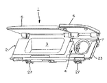
図7は車両用コンソール等に組み込まれる小物入れ装置例を示している。この小物入れ装置1は、本体2が収納用凹所3,4を左右に形成しており、各凹所3,4が対応するリッド5,6により開閉される。凹所3は、凹所4より一回り大きな格納空間を形成している。凹所4は、開口した受部7を底面側に形成し、図1等に示されるように該受部7にソケット部8が装着される。このソケット部8は、乗員が必要に応じリッド6を開閉して各種機器類の電源接続部として利用され、不使用時にリッド6で閉じられることで塵等の進入を防いで安全性を確保している。
FIG. 7 shows an example of an accessory case incorporated in a vehicle console or the like. In the accessory case 1, the
以上の小物入れ装置1に採用されるリッド開閉装置は、通常、リッドが付勢手段により開方向へ付勢されており、該付勢手段の付勢力に抗して開位置から閉位置へ回動切り換えられ、該閉位置で本体及びリッドの一方に設けられたラッチ手段に対し他方に設けられたストライカを係止して閉状態に保持され、前記係止を解除操作することで前記付勢手段により閉位置から開位置へ自動的に回動切り換えられる。 In the lid opening / closing device employed in the accessory case 1 described above, the lid is normally urged in the opening direction by the urging means, and the lid opening / closing device rotates from the open position to the closed position against the urging force of the urging means. In the closed position, the striker provided on the other side is locked to the latch means provided on one side of the main body and the lid, and is held in the closed state. The rotation is automatically switched from the closed position to the open position by the means.
また、前記ラッチ手段としては、使い勝手を良好にする上で、特許文献1に開示されているようにハートカムを利用したプッシュ・プッシュ機構が採用されている。この作動特徴は、リッドに対する閉方向への押し操作により前記ストライカを係止し、リッドに対する次の同方向への押し操作により前記係止を解除する係止機構である。
上記した小物入れ装置1のうち、リッド6が従来のように閉方向への押し操作によりロック状態に係止され、次の押し操作により係止解除されて開位置へ回動切り換えられる態様だと次のようなことが問題となる。すなわち、この構造では、凹所4がリッド6の開位置で全開しているため塵や小物等が不用意に入ってソケット部8にショートしたり、子供等が手や指を差し込んでソケット部8にショートする虞もある。また、このような対策としては、リッド6を常に付勢手段の付勢力により閉位置の方向へ付勢しておくことも考えられる。しかし、その場合は、まず、リッド6を付勢力に抗して開方向へ回動操作する上で、操作用指掛け部をリッド上面や前端側に形成しなくてはならず、該指掛け部の存在により外観低下が避けられないこと、リッド6が常に閉じ方向へ付勢されていると、ソケット部8に電気接続したコード類のうち、凹所4への挿入部分が本体2とリッド6との間に強く挟み込まれて摩耗劣化し易くなる。
In the accessory case 1 described above, when the
本発明の目的は、以上のような課題を簡易に解消して、塵等が本体内に不用意に入り難くしたり、手や指が不用意に本体内へ挿入するという虞を無くし、それにより外観特定及び使い勝手を維持して、安全性や信頼性を向上することにある。 The object of the present invention is to easily solve the above-mentioned problems and eliminate the possibility that dust and the like will not easily enter into the main body or that hands and fingers may be inadvertently inserted into the main body. Thus, it is to improve the safety and reliability by maintaining appearance identification and usability.
請求項1の発明は、リッドを本体の対応面に対し該対応面を覆う閉位置と開放する開位置とに回動切り換えるリッド開閉装置において、前記リッドを閉位置から開位置に至る途中位置まで付勢移動するための第1付勢手段と、 前記リッドを開位置から前記途中位置まで付勢移動するための第2付勢手段と、前記リッド及び前記本体の一方に設けられたストライカと、他方に設けられて前記リッドの閉方向への押し操作により前記ストライカを係止して前記リッドを閉位置に保ち、かつ、前記リッドの同方向への押し操作により前記係止を解除可能なラッチ手段とを備え、前記リッドを、前記閉位置から途中位置まで前記第1付勢手段の付勢力により自動で回動し、前記途中位置から開位置へ前記第2付勢手段の付勢力に抗して手動で回動することを特徴としている。
また、請求項5の発明は、以上の発明を小物入れ装置に適用した態様であり、本体が上向きの開口部を形成し、前記開口部をリッドにより開閉する小物入れ装置において、前記リッドが請求項1〜4の何れかに記載のリッド開閉装置により回動切り換えられると共に、前記途中位置で当該リッド先端と前記本体との間に少なくとも指掛け用として使用される隙間を形成することを特徴としている。
According to a first aspect of the present invention, in the lid opening and closing device that switches the lid to a closed position that covers the corresponding surface with respect to the corresponding surface of the main body and an open position that opens the lid, the lid is moved from the closed position to an intermediate position to the open position. A first urging means for urging and moving; a second urging means for urging and moving the lid from the open position to the midway position; and a striker provided on one of the lid and the main body; A latch provided on the other side for locking the striker by pushing the lid in the closing direction to keep the lid in the closed position, and releasing the locking by pushing the lid in the same direction. Means for automatically rotating the lid from the closed position to an intermediate position by the urging force of the first urging means and resisting the urging force of the second urging means from the intermediate position to the open position. And rotate manually It is characterized by that.
The invention of
以上の各発明では、リッドが本体に回動可能に枢支され、本体の対応面(例えば、開口部や操作部等)に対し第1付勢手段の付勢力に抗して覆う閉位置と、該閉位置より第1付勢手段の付勢力で開方向へ所定角だけ回動される途中位置と、該途中位置より第2付勢手段の付勢力に抗して回動される開位置(通常は全開位置を意味している)とに回動切り換えられる。そして、この構造では、リッドが閉位置から第1付勢手段の付勢力により途中位置に回動されると、リッド先端と本体側との間に所定大の隙間(通常は5〜15mm程度の隙間)を形成する。該隙間は、使用者がリッドを途中位置から開位置へ回動操作する際に指掛け用として利用する以外に、実施例のごとく本体内のソケット部に電機接続したコード類を引き出すための引出用クリアランスとして利用される。また、この構造では、リッドが第2付勢手段の付勢力に抗して途中位置から開位置へ回動されるが、開位置でリッドに対する押力を解放すると、第2付勢手段の付勢力により再び途中位置まで自動的に回動されるため、実施例のごとく本体内のソケット部に対して塵等の進入の虞を極力無くしたり、手や指等を本体内に挿入して接触するというような虞を確実に解消できる。 In each of the above inventions, the lid is pivotally supported by the main body so as to cover the corresponding surface of the main body (for example, an opening or an operating portion) against the biasing force of the first biasing means; A halfway position rotated by a predetermined angle in the opening direction by the biasing force of the first biasing means from the closed position, and an open position pivoted against the biasing force of the second biasing means from the halfway position (Normally, it means a fully open position). In this structure, when the lid is rotated from the closed position to the middle position by the urging force of the first urging means, a predetermined large gap (usually about 5 to 15 mm) is provided between the lid tip and the main body side. Gap). The gap is used for pulling out cords electrically connected to the socket portion in the main body as in the embodiment, in addition to being used as a finger hook when the user rotates the lid from the midway position to the open position. Used as clearance. Further, in this structure, the lid is rotated from the midway position to the open position against the urging force of the second urging means, but when the pressing force against the lid is released at the open position, the urging force of the second urging means is applied. As it is automatically rotated to the middle position again by force, as in the embodiment, there is no possibility of dust entering the socket part in the main unit, or a hand or finger is inserted into the main unit to make contact It is possible to surely eliminate the fear of doing.
以上の各発明は、請求項2〜4のように具体化することがより好ましい。すなわち、
・第1に、前記ラッチ手段が前記本体に設けられ、前記ストライカが前記リッドに枢支されたアームに設けられている構成である(請求項2)。
・第2に、前記第1付勢手段が前記本体と前記アームとの間に介在されて、前記アームを前記リッドと一体的に途中位置から閉位置へ回動可能にしている構成である(請求項3)。
・第3に、前記リッドは、前記アームが前記本体に設けられたストッパ部に当接した状態で途中位置に保持され、前記アームに対し相対的に回動しながら途中位置から開位置へ切り換えられる構成である(請求項3)。
Each of the above inventions is more preferably embodied as in the second to fourth aspects. That is,
First, the latch means is provided in the main body, and the striker is provided in an arm pivotally supported by the lid (Claim 2).
Second, the first urging means is interposed between the main body and the arm so that the arm can be rotated integrally with the lid from a midway position to a closed position ( Claim 3).
Third, the lid is held at an intermediate position in a state where the arm is in contact with a stopper portion provided on the main body, and is switched from an intermediate position to an open position while rotating relative to the arm. (Claim 3).
上述したように、本発明にあっては次のような利点を具備できる。
・請求項1及び4の各発明では、リッドが閉位置と、途中位置と、開位置とに回動切り換えられることと、リッドが第1付勢手段の付勢力により閉位置から途中位置まで切り換えられたり、リッドが第2付勢手段の付勢力に抗して途中位置から開位置へ切り換えられるため、課題に挙げたような問題を比較的簡易に解消して、本体内への塵等の進入を防止したり、手や指を不用意に本体内へ挿入するという虞を無くし、それにより、例えば本体内にソケット部等を付設するような場合に外観特性を維持して安全性等を向上できる。
・請求項2の発明では、例えば、リッド側にアームを介してストライカを付設することにより、部材同士の配置に規制され難くしたり、外観特性を維持できるようにする。
・請求項3の発明では、アームがリッドの途中位置でストッパ部と当接するため、リッドが途中位置で安定した状態で、かつ、第2付勢手段の付勢力に抗して開方向へ回動操作可能に保持される。
As described above, the present invention can have the following advantages.
In the first and fourth aspects of the present invention, the lid is pivotally switched between the closed position, the midway position, and the open position, and the lid is switched from the closed position to the midway position by the biasing force of the first biasing means. Or the lid can be switched from an intermediate position to an open position against the urging force of the second urging means. This eliminates the risk of preventing intrusion or inadvertent insertion of a hand or finger into the main body, thereby maintaining the appearance characteristics when attaching a socket or the like in the main body, for example. It can be improved.
In the invention of
In the invention of
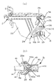
本発明の最良な形態を図面の実施例を参照しながら説明する。なお、図1及び図2は小物入れ装置を示し、図1(a)は側面図、図1(b)は図2(a)の略B−B線に沿った縦断面図、図2(a)は平面図、図2(b)は図2(a)の略A−A線に沿った縦断面図である。図3は小物入れ装置を背面側から見た要部の模式外観図、図4はリッドの裏面側を各付勢手段等と共に示す模式外観図である。図5と図6はリッド開閉装置の作動図である。以下の説明では、小物入れ装置とリッド開閉装置及びその作動の順に詳述する。 The best mode of the present invention will be described with reference to embodiments of the drawings. 1 and FIG. 2 show an accessory case, FIG. 1 (a) is a side view, FIG. 1 (b) is a longitudinal sectional view taken along the line BB in FIG. 2 (a), and FIG. FIG. 2A is a plan view, and FIG. 2B is a longitudinal sectional view taken along line AA in FIG. FIG. 3 is a schematic external view of the main part of the accessory case when viewed from the back side, and FIG. 4 is a schematic external view showing the back side of the lid together with each urging means. 5 and 6 are operation diagrams of the lid opening / closing device. In the following description, the accessory case device, the lid opening / closing device and the operation thereof will be described in detail.
(小物入れ装置)実施例の小物入れ装置1は、図7に示された車両用コンソールに組み込まれる小物入れ装置1とほぼ同じ形状のもので、本体2が左右に収納用凹所3,4を有し、各凹所3,4が対応するリッド5,6により開閉される。凹所3は、凹所4より一回り大きな格納空間を形成しており、回動式のリッド5により開閉される。このリッド5は、従来と同じく不図示の付勢手段により開方向へ付勢されており、該付勢手段の付勢力に抗して開位置から閉位置へ回動切り換えられ、該閉位置で本体2側に取り付けられたラッチ手段に対しリッド5側に付設されたストライカを係止して閉位置に保持され、前記係止を解除操作することで前記付勢手段により閉位置から開位置へ切り換えられる。これに対し、凹所4は、筒形の受部7を底面側に形成し、図1等に示されるように該受部7に電源接続用のソケット部8が装着され、又、凹所4が本発明のリッド開閉装置10を適用したリッド6により開閉される。そして、ソケット部8は、必要に応じリッド6を開閉して各種機器類の電源接続部として利用される。
(Accessory device) The accessory device 1 of the embodiment has substantially the same shape as the accessory device 1 incorporated in the vehicle console shown in FIG. The
次に、以上の小物入れ装置1において、本発明のリッド開閉装置10と関係する本体2及びリッド6の構成を説明する。本体2は、図1〜図3に示されるように、下両側に突設されている縦壁21,22と、凹所3と凹所4との各区画部の境界に突設されている中間縦壁23と、中間縦壁23から受部7側へ突設されている複数のストッパ部24と、中間縦壁23の下側からストッパ部24と同方向へ突設されている略矩形枠状の取付枠25と、下後側に突設されている対の支持壁26,26などを一体に有している。このうち、ストッパ部24と取付枠25とは、後述するアーム13及びラッチ手段15に対応した間隔が設定されている。各ストッパ部24は、所定の勾配を持って突出された片状となっていて、下側の先端面がアーム13に対する当接部に設定されている。取付枠25には後述するラッチ手段15が装着される。各支持壁26には、同軸線上に設けられて後述するシャフト29を回動自在に支持する軸孔と、段差状に形成されて後述するコイルスプリング11,12の他端11b,12bを係止する係止部とが設けられている。なお、符号27,28はコンソール側への位置決め兼用の取付片である。
Next, in the accessory case 1 described above, the configuration of the
リッド6は、図4や図5に示されるように、アウタ部材30にインナ部材31を装着した構成である。インナ部材31には、下後両側に突出されている支持部32,34と、支持部32,34に対応して突出されているばね受け33,36と、支持部32と支持部34との間に突出されている当接部37とが設けられている。支持部32は半円弧状をなし、軸孔32aを形成している。支持部34は、支持部32より大きな円弧状でかつその肉厚内に嵌合溝35を形成し、又、軸孔34aを軸孔32aと同軸線上に形成している。嵌合溝35は、後側と下側とが開口され、前側が閉じられている(図5を参照)。ばね受け33,34は、支持部32及び支持部34の対向している側面から略半筒状に突設され、対応するコイルスプリング11,12のばね巻部をインナ部材31との間で保持する。なお、インナ部材31の下前側は、図1に示されるように2箇所に取り付けられた緩衝材38を有し、本体2の上面体対応部に緩衝材38を介して当接するようになっている。
As shown in FIGS. 4 and 5, the
以上のリッド6は、本体2に対しシャフト29が支持部32の軸孔32a、前記各支持壁26,26の軸孔、支持部34の軸孔34a、中間縦壁23の上側に設けられた軸孔に挿通された状態で回動切換可能に枢支されるが、その際、次に述べるリッド開閉装置10の各部材が対応箇所に組み付けられることになる。
In the
(リッド開閉装置)実施例のリッド開閉装置10は、リッド6を本体2の凹所4等に対し該凹所4を覆って塞ぐ閉位置と開放する開位置とに回動切り換えるものである。構成部材は、第1コイルスプリング11及び第2コイルスプリング12と、リッド6の支持部34に枢支されるアーム13及び該アーム13に付設されたストライカ14と、本体2側に付設されてストライカ14と係脱するラッチ手段15とを備えている。
(Lid Opening / Closing Device) The lid opening /
このうち、第1コイルスプリング11は、リッド6を閉位置から開位置に至る途中位置まで付勢移動するためのもので、両端11a,11bが比較的長く形成されている。第2コイルスプリング12は、リッド6を開位置から前記途中位置まで付勢移動するためのもので、両端12a,12bが比較的長く形成されている。そして、第1コイルスプリング11は、ばね受け36にばね巻部を乗せた状態で軸孔34aへ向かうシャフト29の軸回りに配置され、一端12aが対応支持壁26の係止部に係止され、他端12bがばね圧を発現しながら後述するアーム13の係止部13cに掛け止めされる(図5参照)。第2コイルスプリング12は、ばね受け33にばね巻部を乗せた状態で軸孔32aを貫通しくるシャフト29の軸回りに配置されて、一端12aがリッド6の下面側に係止され、他端11bがばね圧を発現しながら対応支持壁26の係止部に掛け止めされる。
Of these, the
アーム13は、図3及び図5に示されるように上下に細長い片状をなし、上部に設けられた軸孔13aと、下端13bの少し上に位置した側面部に突設されたスイライカ14と、正面のうち上下略中間に位置した箇所に突設されている係止部13cとを一体に形成している。また、板厚的には、係止部13cより上側が支持部34の嵌合溝35に余裕を持って入り込む薄肉板状に形成され、それよりも板側が相対的に厚肉板状に形成されている。ストライカ14は軸の先端に係合突起14aを形成している。そして、このアーム13は、リッド6が本体2にシャフト29を介し取り付けられるときに、上側を支持部34の嵌合溝35に挿入し、軸孔13aを支持部34の軸孔34aに一致させた状態から、シャフト29を支持部34の内側軸孔34a、軸孔13a、支持部34の外側軸孔34aへ挿通操作する。その後、第1コイルスプリング11は前述した通り、一端11aが対応支持壁26の係止部に係止され、他端11bがばね圧を発現しながらアーム13の係止部13cに掛け止めされる。すると、アーム13は、第1コイルスプリング11の付勢力により前方へ回動されて、上側が嵌合溝35に最大まで入り込み、下前方側がストッパ部24に当接して回動を規制する。
As shown in FIGS. 3 and 5, the
ラッチ手段15は、図5及び図6に示されるように本体2の取付枠25に挿入保持されて、リッド6の閉方向への押し操作によりストライカ14を係止してリッド6を閉位置に保持し、かつ、リッド6の同方向への押し操作により前記係止を解除可能なプッシュ・プッシュ係止機構である。この構造は、例えば、前後面を開口したケース40、ケース40に収容されて、ストライカ14の係合突起14aを係脱する対の係止片41を有する摺動体42、摺動体42を一方向に付勢する不図示のスプリング、摺動体42に設けられたハートカム溝43、ケース40内に軸支されたトレーサ44、トレーサ44に突設されてハートカム溝43と係合し摺動体42の摺動によりハートカム溝43を一巡するピン45等を有している。そして、ラッチ手段15は、ケース40が取付枠25に対し挿入状態で両側の弾性係合部40aを介して抜け止め装着される。但し、ラッチ手段15は、この構造のもの限られず、例えば、特許文献1に開示のプッシュ・プッシュ機構でも差し支えない。
The latch means 15 is inserted and held in the mounting
(作動)以上のリッド開閉装置10では、本体2に対しリッド6を次のような操作により閉位置、途中位置、開位置とに切り換える。
ア)、図1の実線及び図5は、リッド6が図6の実線で示される途中位置から閉方向への押し操作により回動されて、ラッチ手段15にストライカ14を係止した閉位置を示している。すなわち、この場合には、リッド6が閉方向へ押されて回動されると、係合突起14aが摺動体42に突き当たり、不図示のスプリングの付勢力に抗して摺動体42をケース40の奥へ摺動する。これと連動して、両係止片41はケース40内に引き込まれつつ係合突起14aを間に挟み込む。同時に、ピン45とハートカム溝43との係合によって係止片41が後退位置で係止される。この結果、リッド6は、第1コイルスプリング11の付勢力に抗して閉位置に保持される。
(Operation) In the lid opening /
1) The solid line in FIG. 1 and FIG. 5 show the closed position in which the
イ)、リッド6を開位置にするには、まず、リッド6を途中位置に回動切り換える。この場合には、リッド6を更に閉方向へ押した後、リッド6への押し力を解放する。すると、ラッチ手段15は、リッド6の閉方向への押し操作によりじピン45とハートカム溝43との係合が外れ、同時に摺動体42が不図示のスプリングの付勢力により押されて、両係止片41をケース40の前方へ大きく突出する。この結果、係合突起14aは、両係止片41による挟み込みから外れて係止状態が解除される。このため、リッド6は、第1コイルスプリング11の付勢力により閉位置から開方向へ回動されて、アーム13がストッパ部24に当接した状態、つまり途中位置に自動で切り換えられる。この途中位置では、リッド6の先端側と本体2の上面との間に所定の隙間を形成する。該隙間は、指掛け用として好適な5〜15mm程度に設定されている。
B) In order to set the
ウ)、リッド6を途中位置から開位置にする場合は、図6の実線に示される前記した隙間に指等を引っ掛け、第2コイルスプリング12の付勢力に抗してリッド6を想像線で示す開方向へ押しなから回動操作する。この形態では、リッド6が開方向へ回動されて、上記した当接部37が支持壁26,26の対応部に当接した段階でリッド6の全開位置となる。すなわち、支持壁26,26はリッド6の開方向へのストッパとしても機能する。使用者は、リッド6を開位置に切り換えた状態で、凹所4内のソケット部8へ各種機器類の接続部を接続操作することになる。また、リッド6は、開方向への押し力が解放されると、第2コイルスプリング12の付勢力により途中位置まで回動される。このため、ソケット部8を使用している間は、リッド6が途中位置に保持されており、例えば、前記したリッド6の先端側と本体2の上面との間に形成される隙間から各種機器類のコート類を凹所4の内外へ配置することができる。
C) When the
以上のように、本発明のリッド開閉装置及びそれを適用した小物入れ装置は、課題に挙げたような問題を一掃して塵等が本体内に不用意に入り難くしたり、子供等が手や指を不用意に本体内へ進入するという虞を確実に無くすことができる。勿論、本発明は、上記した実施例に何ら制約されるものではなく、各手段の細部については種々変更可能なものである。一例としては、各コイルスプリング11,12を板ばねやトーションばねにて構成したり、ストライカ14を本体2側に設けると共にラッチ手段15をリッド6側に付設することである。
As described above, the lid opening / closing device of the present invention and the accessory case to which the lid opening / closing device of the present invention is applied, wipes out the problems as listed above and makes it difficult for dust and the like to enter the main body inadvertently. It is possible to reliably eliminate the risk of inadvertently entering the body with the fingers. Of course, the present invention is not limited to the above-described embodiments, and details of each means can be variously changed. For example, each of the coil springs 11 and 12 is constituted by a plate spring or a torsion spring, or the
1…小物入れ装置
2…本体(3,4は凹所、7は受部)
5,6…リッド
10…リッド開閉装置
11…第1コイルスプリング(第1付勢手段で、11a,11bは両端部)
12…第2コイルスプリング(第2付勢手段で、12a,12bは両端部)
13…アーム
14…ストライカ
15…ラッチ手段(プッシュ・プッシュ係止機構)
24…ストッパ部
DESCRIPTION OF SYMBOLS 1 ... Small
5, 6 ...
12 ... 2nd coil spring (the 2nd biasing means, 12a and 12b are both ends)
13 ...
24 ... Stopper
Claims (5)
前記リッドを閉位置から開位置に至る途中位置まで付勢移動するための第1付勢手段と、 前記リッドを開位置から前記途中位置まで付勢移動するための第2付勢手段と、
前記リッド及び前記本体の一方に設けられたストライカと、他方に設けられて前記リッドの閉方向への押し操作により前記ストライカを係止して前記リッドを閉位置に保ち、かつ、前記リッドの同方向への押し操作により前記係止を解除可能なラッチ手段とを備え、
前記リッドを、前記閉位置から途中位置まで前記第1付勢手段の付勢力により自動で回動し、前記途中位置から開位置へ前記第2付勢手段の付勢力に抗して手動で回動することを特徴とするリッド開閉装置。 In the lid opening and closing device that switches the lid to a closed position that covers the corresponding surface and an open position that opens the corresponding surface of the main body,
A first urging means for urging and moving the lid from a closed position to an intermediate position from the open position; a second urging means for urging and moving the lid from the open position to the intermediate position;
A striker provided on one of the lid and the main body, and a striker provided on the other to lock the striker by pushing the lid in the closing direction to keep the lid in the closed position, and the same lid Latch means capable of releasing the locking by pushing in the direction,
The lid is automatically rotated from the closed position to an intermediate position by the urging force of the first urging means, and is manually rotated against the urging force of the second urging means from the intermediate position to the open position. A lid opening and closing device characterized by moving.
In the accessory case in which the main body forms an upward opening and the opening is opened and closed by the lid, the lid is rotated and switched by the lid opening and closing device according to any one of claims 1 to 4, and the intermediate position The accessory case is characterized in that at least a gap for use as a finger hook is formed between the lid tip and the main body.
Priority Applications (5)
| Application Number | Priority Date | Filing Date | Title |
|---|---|---|---|
| JP2004063321A JP2005247232A (en) | 2004-03-08 | 2004-03-08 | Lid opening/closing device, and storage compartment device using it |
| KR1020050013583A KR100625925B1 (en) | 2004-03-08 | 2005-02-18 | Lid opening/closing device and small article storage device using the same |
| CNB2005100510772A CN100382993C (en) | 2004-03-08 | 2005-03-03 | Lid operating device and storage device using the same |
| US11/070,303 US7243970B2 (en) | 2004-03-08 | 2005-03-03 | Lid operating device and storage device using the same |
| GB0504525A GB2412097B (en) | 2004-03-08 | 2005-03-04 | Lid operating device and storage device using the same |
Applications Claiming Priority (1)
| Application Number | Priority Date | Filing Date | Title |
|---|---|---|---|
| JP2004063321A JP2005247232A (en) | 2004-03-08 | 2004-03-08 | Lid opening/closing device, and storage compartment device using it |
Publications (1)
| Publication Number | Publication Date |
|---|---|
| JP2005247232A true JP2005247232A (en) | 2005-09-15 |
Family
ID=34464055
Family Applications (1)
| Application Number | Title | Priority Date | Filing Date |
|---|---|---|---|
| JP2004063321A Pending JP2005247232A (en) | 2004-03-08 | 2004-03-08 | Lid opening/closing device, and storage compartment device using it |
Country Status (5)
| Country | Link |
|---|---|
| US (1) | US7243970B2 (en) |
| JP (1) | JP2005247232A (en) |
| KR (1) | KR100625925B1 (en) |
| CN (1) | CN100382993C (en) |
| GB (1) | GB2412097B (en) |
Cited By (3)
| Publication number | Priority date | Publication date | Assignee | Title |
|---|---|---|---|---|
| JP2012096167A (en) * | 2010-11-02 | 2012-05-24 | Sumitomo Electric Ind Ltd | Gas decomposition element, power generation device and gas decomposition method |
| JP2022167232A (en) * | 2021-04-22 | 2022-11-04 | 森六テクノロジー株式会社 | Vehicular storage device |
| JP2022167233A (en) * | 2021-04-22 | 2022-11-04 | 森六テクノロジー株式会社 | Vehicular storage device |
Families Citing this family (17)
| Publication number | Priority date | Publication date | Assignee | Title |
|---|---|---|---|---|
| DE10228399A1 (en) * | 2002-06-25 | 2004-01-15 | Daimlerchrysler Ag | Storage compartment for a vehicle |
| KR100543759B1 (en) * | 2003-12-18 | 2006-01-23 | 현대모비스 주식회사 | Opening and closing structure of a tray in a car |
| JP4615269B2 (en) * | 2004-08-18 | 2011-01-19 | 株式会社ニフコ | Acceleration / deceleration mechanism and vehicle accessory case equipped with the acceleration / deceleration mechanism |
| KR100645186B1 (en) * | 2005-07-07 | 2006-11-10 | 현대모비스 주식회사 | Center upper tray |
| US7175217B1 (en) * | 2006-02-03 | 2007-02-13 | Toyota Technical Center Usa, Inc. | Vehicle power outlet bezel assembly |
| JP5108358B2 (en) * | 2007-04-06 | 2012-12-26 | 株式会社ニフコ | Lid opening / closing device |
| US7731254B2 (en) * | 2008-01-09 | 2010-06-08 | Toyota Motor Engineering & Manufacturing North America, Inc. | Motor vehicle center console assembly having a container assembly with a flush door |
| FR2961145B1 (en) * | 2010-06-15 | 2012-06-08 | Peugeot Citroen Automobiles Sa | PAVILION CONSOLE OF A MOTOR VEHICLE |
| JP5561154B2 (en) * | 2010-07-30 | 2014-07-30 | 豊田合成株式会社 | Shutter case |
| FR2976876B1 (en) * | 2011-06-23 | 2013-11-29 | Faurecia Interieur Ind | STORAGE DEVICE FOR A MOTOR VEHICLE COMPRISING LOCKING MEANS TO PREVENT AN INVOLUNTARY OPENING OF THE DEVICE |
| CN105725713A (en) * | 2016-04-12 | 2016-07-06 | 王本 | Plane with scrap collecting function |
| EP3249142B1 (en) * | 2016-05-24 | 2021-11-17 | FCA Italy S.p.A. | Covering device for a trunk of a motor vehicle |
| DE102016011206A1 (en) * | 2016-09-12 | 2018-03-15 | GM Global Technology Operations LLC (n. d. Ges. d. Staates Delaware) | Armrest device and motor vehicle with the armrest device |
| US20190111849A1 (en) * | 2017-10-16 | 2019-04-18 | Matthew Thomas Besley | Open Space Organizer Apparatus and System |
| EP3947041A4 (en) * | 2019-03-25 | 2022-12-28 | Shanghai Yanfeng Jinqiao Automotive Trim Systems Co. Ltd | Vehicle interior component |
| US11161441B2 (en) * | 2019-09-20 | 2021-11-02 | Ford Global Technologies, Llc | Vehicle console assembly |
| DE102022102402A1 (en) | 2022-02-02 | 2023-08-03 | Dr. Ing. H.C. F. Porsche Aktiengesellschaft | Charging flap arrangement or tank flap arrangement of a motor vehicle and motor vehicle |
Citations (3)
| Publication number | Priority date | Publication date | Assignee | Title |
|---|---|---|---|---|
| JPH0565687U (en) * | 1992-02-14 | 1993-08-31 | 株式会社ニフコ | Small vehicle storage device with cup holder |
| JPH0737812U (en) * | 1993-12-24 | 1995-07-14 | 株式会社ニフコ | Vehicle accessory storage device |
| JP2000272426A (en) * | 1999-03-23 | 2000-10-03 | Araco Corp | Console box |
Family Cites Families (6)
| Publication number | Priority date | Publication date | Assignee | Title |
|---|---|---|---|---|
| JP2594955Y2 (en) * | 1993-03-15 | 1999-05-24 | 株式会社ニフコ | Accessory storage device for vehicles |
| AU8463898A (en) * | 1997-07-15 | 1999-02-10 | Seong Soo Kim | Trunk lid emergency opening apparatus of automobile |
| JP3736832B2 (en) | 1999-11-30 | 2006-01-18 | 株式会社今仙電機製作所 | Overhead console |
| JP4629240B2 (en) | 2001-01-19 | 2011-02-09 | 株式会社ニフコ | Opening and closing device for door |
| JP4111308B2 (en) | 2001-12-13 | 2008-07-02 | 株式会社イノアックコーポレーション | Storage box with lid |
| JP3935020B2 (en) * | 2002-07-31 | 2007-06-20 | 株式会社ニフコ | Lid opening / closing mechanism and vehicle storage device |
-
2004
- 2004-03-08 JP JP2004063321A patent/JP2005247232A/en active Pending
-
2005
- 2005-02-18 KR KR1020050013583A patent/KR100625925B1/en not_active IP Right Cessation
- 2005-03-03 CN CNB2005100510772A patent/CN100382993C/en not_active Expired - Fee Related
- 2005-03-03 US US11/070,303 patent/US7243970B2/en not_active Expired - Fee Related
- 2005-03-04 GB GB0504525A patent/GB2412097B/en not_active Expired - Fee Related
Patent Citations (3)
| Publication number | Priority date | Publication date | Assignee | Title |
|---|---|---|---|---|
| JPH0565687U (en) * | 1992-02-14 | 1993-08-31 | 株式会社ニフコ | Small vehicle storage device with cup holder |
| JPH0737812U (en) * | 1993-12-24 | 1995-07-14 | 株式会社ニフコ | Vehicle accessory storage device |
| JP2000272426A (en) * | 1999-03-23 | 2000-10-03 | Araco Corp | Console box |
Cited By (5)
| Publication number | Priority date | Publication date | Assignee | Title |
|---|---|---|---|---|
| JP2012096167A (en) * | 2010-11-02 | 2012-05-24 | Sumitomo Electric Ind Ltd | Gas decomposition element, power generation device and gas decomposition method |
| JP2022167232A (en) * | 2021-04-22 | 2022-11-04 | 森六テクノロジー株式会社 | Vehicular storage device |
| JP2022167233A (en) * | 2021-04-22 | 2022-11-04 | 森六テクノロジー株式会社 | Vehicular storage device |
| JP7341183B2 (en) | 2021-04-22 | 2023-09-08 | 森六テクノロジー株式会社 | Vehicle storage device |
| JP7383663B2 (en) | 2021-04-22 | 2023-11-20 | 森六テクノロジー株式会社 | Vehicle storage device |
Also Published As
| Publication number | Publication date |
|---|---|
| GB2412097A (en) | 2005-09-21 |
| GB2412097B (en) | 2007-06-06 |
| GB0504525D0 (en) | 2005-04-13 |
| KR100625925B1 (en) | 2006-09-20 |
| KR20060042987A (en) | 2006-05-15 |
| US7243970B2 (en) | 2007-07-17 |
| CN1666909A (en) | 2005-09-14 |
| US20050205591A1 (en) | 2005-09-22 |
| CN100382993C (en) | 2008-04-23 |
Similar Documents
| Publication | Publication Date | Title |
|---|---|---|
| JP2005247232A (en) | Lid opening/closing device, and storage compartment device using it | |
| WO2009081983A1 (en) | Safety device, and opening and closing mechanism | |
| JP2007161288A (en) | Lid body locking structure | |
| JP2011094440A (en) | Lock device and door using the same | |
| KR100575157B1 (en) | Computer | |
| JP2009180883A (en) | Electronic device | |
| JP2008133656A (en) | Electric lock | |
| JP2004059023A (en) | Lid | |
| JP4966883B2 (en) | Open / close assist mechanism | |
| JP2006299691A (en) | Handle device and fittings | |
| JP5479217B2 (en) | Locking and unlocking device for opening and closing body in article storage fixture | |
| KR200471689Y1 (en) | Locking assembly for a storage container of car | |
| JP2004058731A (en) | Portable machine slot device | |
| KR101569991B1 (en) | Door locking device for cabinet | |
| JP2019107265A (en) | Handle case in furniture | |
| WO2006046451A1 (en) | Lock device | |
| JP2008196279A (en) | Lid opening operation apparatus | |
| JP2007190936A (en) | Hinge device of deck board | |
| JP3988235B2 (en) | Cassette lid opening / closing mechanism of recording / reproducing apparatus | |
| JP2016123807A (en) | Lock device | |
| JP5154287B2 (en) | Vibration lock device | |
| JP6737719B2 (en) | Locking device for movable units | |
| JP2011153450A (en) | Article storage furniture with opening/closing body | |
| JP4464795B2 (en) | Storage device with double doors | |
| KR100715900B1 (en) | Fob key holder |
Legal Events
| Date | Code | Title | Description |
|---|---|---|---|
| A621 | Written request for application examination |
Free format text: JAPANESE INTERMEDIATE CODE: A621 Effective date: 20061221 |
|
| A131 | Notification of reasons for refusal |
Free format text: JAPANESE INTERMEDIATE CODE: A131 Effective date: 20081111 |
|
| A977 | Report on retrieval |
Free format text: JAPANESE INTERMEDIATE CODE: A971007 Effective date: 20081112 |
|
| A02 | Decision of refusal |
Free format text: JAPANESE INTERMEDIATE CODE: A02 Effective date: 20090402 |