JP2005238299A - Vacuum die casting apparatus and vacuum die casting method - Google Patents
Vacuum die casting apparatus and vacuum die casting method Download PDFInfo
- Publication number
- JP2005238299A JP2005238299A JP2004052820A JP2004052820A JP2005238299A JP 2005238299 A JP2005238299 A JP 2005238299A JP 2004052820 A JP2004052820 A JP 2004052820A JP 2004052820 A JP2004052820 A JP 2004052820A JP 2005238299 A JP2005238299 A JP 2005238299A
- Authority
- JP
- Japan
- Prior art keywords
- mold
- slide core
- space
- cover
- die casting
- Prior art date
- Legal status (The legal status is an assumption and is not a legal conclusion. Google has not performed a legal analysis and makes no representation as to the accuracy of the status listed.)
- Pending
Links
Images

Abstract
Description
本発明は、減圧ダイカスト鋳造装置および減圧ダイカスト鋳造方法に関し、より詳しくは、金型要素として固定型および可動型のほかにスライドコアを備えていて、それらの金型要素によって形成される製品形状部空間を予め減圧した上で、その製品形状部空間に溶湯を充填して鋳造を行う減圧もしくは真空ダイカスト鋳造装置とその鋳造方法に関するものである。 The present invention relates to a reduced pressure die casting apparatus and a reduced pressure die casting method, and more specifically, a product shape portion that includes a slide core as a mold element in addition to a fixed mold and a movable mold, and is formed by these mold elements. The present invention relates to a decompression or vacuum die casting apparatus and a casting method for performing casting by filling a molten product into the product shape space after the space has been decompressed in advance.
組織の緻密な高品質の鋳物製品の生産に適した減圧ダイカスト法においては、金型内の減圧度もしくは真空度を保つためのシール技術が重要な要素となる。一般的には、金型のキャビティとして機能することになる製品形状部空間を大気から遮断するために金型の型合わせ面(パーティング面)に弾性を有するゴム等のシール材を配置するようにしており、いわゆる主型二分割タイプの金型には有効である。 In the vacuum die casting method suitable for producing a high-quality cast product with a dense structure, a sealing technique for maintaining the degree of vacuum or vacuum in the mold is an important factor. Generally, an elastic rubber or other sealing material is disposed on the mold mating surface (parting surface) of the mold in order to block the product shape space that will function as a mold cavity from the atmosphere. This is effective for a so-called main type two-part mold.
その一方、より複雑な形状の鋳物製品の鋳造を目的とした金型構造では、主型である固定型や可動型以外にスライドコア(いわゆる可動中子)を併用することが行われており、この場合においても、上記シール技術の延長線として、例えば特許文献1に記載のように、各金型要素同士の合わせ面にシール材を配置することが行われている。
しかしながら、上記のようなスライドコアを併用した金型構造では、シール面自体が単純平面ではなく全体として三次元的なものとなるが故に、シール材の配置だけではそのシール効果が不十分で、必要とするシール性能を長期にわたって維持することがきわめて困難であり、なおも改善の余地を残している。 However, in the mold structure using the slide core as described above, the sealing surface itself is not a simple plane but a three-dimensional one as a whole. It is extremely difficult to maintain the required sealing performance over a long period of time, and there is still room for improvement.
本発明はこのような課題に着目してなされたものであり、とりわけスライドコアを併用する減圧ダイカスト鋳造において、スライドコアそのもののシール構造に依存することなく、製品形状部空間を大気から確実に遮断してその減圧度もしくは真空度を維持することができるようにした減圧ダイカスト鋳造装置と減圧ダイカスト鋳造方法を提供しようとするものである。 The present invention has been made paying attention to such problems, and in particular, in reduced-pressure die casting using a slide core in combination, the product shape part space is surely cut off from the atmosphere without depending on the seal structure of the slide core itself. Thus, a reduced pressure die casting apparatus and a reduced pressure die casting method capable of maintaining the reduced pressure degree or the vacuum degree are provided.
請求項1に記載の発明は、金型要素として固定型と可動型のほかにスライドコアを備え、それらの金型要素によって形成される製品形状部空間を予め減圧した上で、その製品形状部空間に溶湯を充填して鋳造を行う減圧ダイカスト鋳造装置であって、スライドコアの周囲を密閉空間とした上で、このスライドコアの周囲の密閉空間を製品形状部空間の減圧動作と並行して減圧するべく、少なくともスライドコアの周囲を覆って密閉空間を形成するカバーを設けたことを特徴とする。
The invention described in
もちろん、請求項2に記載のように、スライドコアを含む金型全体の周囲を覆って密閉空間を形成するようにしてもよい。
Of course, as described in
また、スライドコアを併用する金型構造では、多くの場合に、請求項3に記載のように、固定型と可動型との接近離間動作に基づいてその型締め型開きが行われるようになっているとともに、その型締め型開き方向と直交する方向から固定型または可動型に対してスライドコアが接近離間可能となっていることから、請求項1,2に記載の発明でもこのような金型構造を想定している。
In many cases, in a mold structure using a slide core, as described in
請求項6に記載の発明は、請求項1に記載の技術を減圧ダイカスト鋳造方法として捉えたものである。すなわち、金型要素として固定型と可動型のほかにスライドコアを備え、それらの金型要素によって形成される製品形状部空間を予め減圧した上で、その製品形状部空間に溶湯を充填して鋳造を行う減圧ダイカスト鋳造方法であって、少なくともスライドコアの周囲をカバーで覆って密閉空間を形成し、製品形状部空間の減圧動作と並行して、カバー内の密閉空間を減圧することを特徴とする。
The invention described in
したがって、請求項1,6に記載の発明では、少なくともスライドコアの周囲をカバーで覆って密閉空間とした上で、この密閉空間を製品形状部空間の減圧動作と並行して減圧するようにすれば、仮にスライドコア相当部にシールが施されていない場合であっても、実質的に製品形状部空間の内外ではその圧力が平衡化される。これにより、製品形状部空間を大気から遮断して、必要とする減圧度もしくは真空度を維持することが可能となる。 Therefore, according to the first and sixth aspects of the present invention, at least the periphery of the slide core is covered with a cover to form a sealed space, and the sealed space is decompressed in parallel with the decompression operation of the product shape portion space. For example, even if the seal core equivalent portion is not sealed, the pressure is substantially balanced inside and outside the product shape portion space. Thereby, it becomes possible to block the product shape part space from the atmosphere and maintain the required degree of vacuum or vacuum.
請求項1,6に記載の発明によれば、少なくともスライドコアの周囲を密閉空間とした上でこの空間をも製品形状部空間とともに減圧することで、スライドコア相当部に特別なシールを施さずして、製品形状部空間の減圧度もしくは真空度を確実に維持できるようになり、鋳物製品の品質が向上する。 According to the first and sixth aspects of the present invention, at least the periphery of the slide core is a sealed space, and this space is decompressed together with the product shape portion space, so that no special seal is applied to the corresponding portion of the slide core. As a result, the decompression degree or the vacuum degree of the product shape portion space can be reliably maintained, and the quality of the cast product is improved.
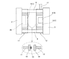
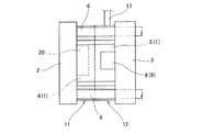
図1〜3は本発明のより具体的な実施の形態を示す図であり、特に図1は型開き状態での金型全体の側面の概略構造を、図2は型締め状態での金型全体の側面の概略構造を、図3の(A),(B)は固定型および可動型それぞれの正面図をそれぞれ示している。 1 to 3 are diagrams showing a more specific embodiment of the present invention. In particular, FIG. 1 shows a schematic structure of the entire side surface of a mold in an opened state, and FIG. 2 shows a mold in a clamped state. 3A and 3B are front views of a fixed type and a movable type, respectively.
図1に示すように、金型1の構成要素であって且つ主型として機能する固定型4および可動型5は、それぞれに独立した固定プラテン2および可動プラテン3に個別に固定支持されていて、可動プラテン3は固定プラテン2から立設した複数のタイバー6にスライド可能に案内支持されている。そして、可動プラテン3をタイバー6に沿って固定プラテン2に対して接近離間動作させることにより、固定型4と可動型5の型締め,型開き動作が行われることになる。
As shown in FIG. 1, the
ここで、固定型4と可動型5との型合わせ面(パーティング面)には、上記のような型締めに際して製品形状部空間Rを密閉空間とするべくシールするためのOリング等のシール材7(図3参照)を配置してある。
Here, the mold fitting surface (parting surface) of the fixed
また、可動型5の周囲には、その可動型5および固定型4とともに金型1を構成することになる複数(ただし、図1〜3では1つのもののみ図示)のスライドコア8が配設されている。これらのスライドコア8は、可動プラテン3に固定されたスライドコア駆動用の油圧シリンダ9によって進退駆動されるようになっている。すなわち、各スライドコア8は、固定型4と可動型5との型締め,型開き方向に対してその直交方向に進退駆動される。そして、スライドコア8が前進動作したときには、可動型5側のコア受容凹部10がスライドコア8を受容して、主型である固定型4および可動型5とともにキャビティたる製品形状部空間Rを形成することになる。
Around the
なお、型締め完了後の製品形状部空間Rでは、予め所定の減圧度もしくは真空度まで減圧された上で溶湯の射出,充填が開始される一方、溶湯の射出,充填が完了する前にその減圧もしくは真空処理が停止されるようになっており、この点に関するかぎり従来の減圧ダイカスト鋳造法と同様である。 In addition, in the product shape part space R after completion of mold clamping, injection and filling of the molten metal are started after the pressure is reduced to a predetermined degree of vacuum or vacuum in advance, while before injection and filling of the molten metal are completed. The decompression or vacuum processing is stopped, and as far as this point is concerned, it is the same as the conventional decompression die casting method.
図3の(A),(B)に示すように、固定型4よび可動型5が個別に固定支持されている固定プラテン2および可動プラテン3には、タイバー6を回避しつつ固定型4および可動型5を取り囲むようにして鋼板製の第1のカバー11もしくは第2のカバー12がそれぞれ立設されている。これらの第1,第2のカバー11,12は、正面視にて互いに同形状の閉ループ状をなすように、固定型4および可動型5と同程度の高さ寸法をもって複数の支柱13を介して立設されているもので、これらの第1,第2のカバー11,12は固定型4および可動型5の関係と同様に型締め,型開き方向で互いに正対している。
As shown in FIGS. 3A and 3B, the
そして、固定型4と可動型5が型締めされたときには、同時に第1,第2のカバー11,12同士がその開口面をもって互いに突き合わされて、固定型4と可動型5およびスライドコア8からなる金型1の周囲には、その金型1全体を取り囲むような単一の比較的大きな密閉空間Cが形成されることになる。
When the fixed
さらに、図1に拡大して示すように、第1,第2のカバー11,12の開口面には、互いの突き合わせ面の拡大化を図るべく幅広のフランジ部14がその全周にわたり形成されていて、いずれか一方のフランジ部14にはゴム等の弾性体からなるシール材15が閉ループ状に配置されている。したがって、先に述べた型締め時には第1,第2のカバー11,12同士もまたフランジ部14をもって互いに突き合わされて、なお且つそのシール材15をもって確実にシールされるように設定されている。なお、シール材15は第1,第2のカバー11,12同士が突き合わされる際の緩衝効果をも発揮するようになっている。
Further, as shown in an enlarged view in FIG. 1, a
そして、第2のカバー12側には真空ポンプ16を減圧源とする減圧用配管17が接続されていることから、この配管17を介していわゆる真空引きを行うことで第1,第2のカバー11,12で覆われた密閉空間Cを減圧することが可能となっている。
Since the
なお、スライドコア8を駆動するための油圧シリンダ9はその長さが大きい故に、第1,第2のカバー11,12を大きくしないかぎりはそれらのカバー11,12内に完全に収容することができないため、本実施の形態では油圧シリンダ9について第2のカバー12を貫通するように突出させ、その油圧シリンダ9と第2のカバー12との間にはパッキン等のシール材を介在させることでシールを施してある。
Since the
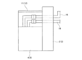
また、図4に示すように、金型要素のうち主型として機能することになる固定型4や可動型5には、製品形状部空間Rの減圧用配管18以外にも冷却水配管19等が付帯することにあるが、これらの主型に付帯することになる配管18,19類については、第1,第2のカバー11,12の貫通を回避するために、背面側の固定プラテン2もしくは可動プラテン3を貫通するような取り回しをもって配設してある。もちろん、各プラテン2,3の貫通部には所定のシールを施してある。
As shown in FIG. 4, the fixed
ここで、上記の第1,第2のカバー11,12によって形成される密閉空間Cは、後述するように金型1内部の製品形状部空間Rの圧力と平衡させるための空間にほかならないことから、減圧効率を高める上では極力その容積が小さい方が望ましい。そこで、本実施の形態では、固定型4および可動型5の周囲に軽量で且つ剛性のある複数の容積減量用ブロック20を配置してある。
Here, the sealed space C formed by the first and
このように構成された減圧ダイカスト鋳造装置によれば、図1,2に示すように、可動型5に対してスライドコア8を前進動作させるとともに、固定型4と可動型5とを突き合わせるべく型締めを行えば、それらの固定型4と可動型5およびスライドコア8をもって密閉された製品形状部空間Rが形成される。同時に、固定プラテン2および可動プラテン3に付帯している第1,第2のカバー11,12同士もまた突き合わされて、金型1の周囲に密閉空間Cが形成される。
According to the reduced pressure die casting apparatus constructed as described above, as shown in FIGS. 1 and 2, the
この状態で、公知の真空引きにより製品形状部空間Rを減圧する一方、それと同時に第2のカバー12に付帯している減圧用配管17を使って真空ポンプ16にて真空引きを行って、金型1の周囲の密閉空間Cを減圧する。
In this state, the product shape portion space R is depressurized by known evacuation, and at the same time, the evacuation is performed by the
ここで、第1,第2のカバー11,12同士の付き合わせ面では図1に示すシール材15によるシールが施されてはいても、可動型5とスライドコア8との突き合わせ面もしくは摺動部では特別なシールが施されていない。そして、その可動型5とスライドコア8との隙間を通して製品形状部空間Rが外部と連通していたと仮定したとしても、金型1の外部空間である密閉空間Cも同様に減圧されているために、結果として製品形状部空間Rと密閉空間Cが圧力平衡することになり、製品形状部空間Rの減圧度が低下するようなことはなく、所定の減圧度を維持できることになる。
Here, the abutting surfaces or sliding surfaces of the
なお、本実施の形態では、先に述べたように密閉空間Cの容積の縮小化を目的として容積減量用ブロック20を配置してあることから、仮にその密閉空間Cの容積が製品形状部空間Rの容積に比べて大きい場合であっても、その密閉空間Cを速やかに減圧することができる。
In the present embodiment, since the
また、密閉空間Cの容積が小さければ小さいほど、より速やかに所定の減圧度にすることができることは先に述べたとおりである。その意味では、上記のように金型1全体を第1,第2のカバー11,12で覆うことなく、少なくともスライドコア8とそれを駆動するための油圧シリンダ9の一部を第1,第2のカバー11,12で覆うことでそのスライドコア8の周囲に密閉空間Cを形成するようにすればより好ましいものとなる。
Further, as described above, the smaller the volume of the sealed space C is, the faster the pressure reduction can be achieved. In that sense, without covering the
製品形状部空間Rが所定の減圧度となったならば、減圧処理を継続したままで、図示しない射出スリーブと射出プランジャを使って溶湯の射出,充填を行い、その溶湯の射出,充填が完了する直前に製品形状部空間R側の減圧を停止する。そして、溶湯の射出,充填が完了して保圧冷却状態に移行したならば金型1の周囲の密閉空間Cの減圧を停止する。
When the product shape part space R reaches a predetermined degree of decompression, the molten metal is injected and filled using an injection sleeve and an injection plunger (not shown) while the decompression process is continued, and the injection and filling of the molten metal are completed. Immediately before the depressurization, the decompression on the product shape part space R side is stopped. When the injection and filling of the molten metal are completed and the pressure holding cooling state is reached, the decompression of the sealed space C around the
その後、所定の保圧冷却時間が経過したならば型開きして鋳物製品を取り出し、以上をもって減圧ダイカスト鋳造のための1サイクルが終了する。 Thereafter, when a predetermined holding pressure cooling time has elapsed, the mold is opened and the cast product is taken out. Thus, one cycle for decompression die casting is completed.
このように本実施の形態によれば、スライドコア8相当部にシールを施さなくても必要な減圧度を容易に維持できることから、減圧ダイカスト鋳造法本来の組織の緻密な鋳物製品を鋳造でき、製品の品質向上に大きく寄与できることになる。
Thus, according to the present embodiment, the required degree of reduced pressure can be easily maintained without sealing the portion corresponding to the
1…金型
2…固定プラテン
3…可動プラテン
4…固定型(金型要素)
5…可動型(金型要素)
8…スライドコア(金型要素)
9…油圧シリンダ
11…第1のカバー
12…第2のカバー
15…シール材
16…真空ポンプ
17…減圧用配管
C…密閉空間
R…製品形状部空間
DESCRIPTION OF
5 ... Moveable type (mold element)
8 ... Slide core (mold element)
DESCRIPTION OF
Claims (7)
スライドコアの周囲を密閉空間とした上で、このスライドコアの周囲の密閉空間を製品形状部空間の減圧動作と並行して減圧するべく、少なくともスライドコアの周囲を覆って密閉空間を形成するカバーを設けたことを特徴とする減圧ダイカスト鋳造装置。 In addition to the fixed mold and movable mold as mold elements, a slide core is provided, and the product shape part space formed by these mold elements is depressurized in advance, and then the product shape part space is filled with molten metal for casting. A vacuum die casting apparatus for performing,
A cover that covers at least the periphery of the slide core and forms a sealed space in order to decompress the sealed space around the slide core in parallel with the decompression operation of the product-shaped portion space after the slide core is used as a sealed space. A reduced-pressure die casting apparatus characterized by comprising:
その型締め型開き方向と直交する方向から固定型または可動型に対してスライドコアが接近離間可能となっていることを特徴とする請求項1または2に記載の減圧ダイカスト鋳造装置。 The clamping mold opening is performed based on the approaching and separating operation of the fixed mold and the movable mold,
3. The reduced pressure die casting apparatus according to claim 1, wherein the slide core is movable toward and away from the fixed mold or the movable mold from a direction orthogonal to the mold clamping mold opening direction.
型締め時に第1,第2のカバー同士が突き合わされることにより、スライドコアを含む金型全体の周囲に密閉空間が形成されるようになっていることを特徴とする請求項3に記載の減圧ダイカスト鋳造装置。 A first cover that covers the periphery of one of the fixed mold and the movable mold, and a second cover that covers the periphery of the other mold element including the slide core,
The sealed space is formed around the entire mold including the slide core by abutting the first and second covers at the time of mold clamping. Vacuum die casting equipment.
少なくともスライドコアの周囲をカバーで覆って密閉空間を形成し、
製品形状部空間の減圧動作と並行して、カバー内の密閉空間を減圧することを特徴とする減圧ダイカスト鋳造方法。 In addition to the fixed mold and movable mold as mold elements, a slide core is provided, and the product shape part space formed by these mold elements is depressurized in advance, and then the product shape part space is filled with molten metal for casting. A vacuum die casting method to perform,
Cover at least the periphery of the slide core with a cover to form a sealed space,
A pressure-reducing die-casting method, wherein the sealed space in the cover is depressurized in parallel with the pressure-reducing operation of the product shape portion space.
製品形状部空間の減圧動作と並行して、カバー内の密閉空間を減圧することを特徴とする請求項6に記載の減圧ダイカスト鋳造方法。 Cover the entire mold including the slide core with a cover to form a sealed space,
The decompression die casting method according to claim 6, wherein the sealed space in the cover is decompressed in parallel with the decompression operation of the product shape portion space.
Priority Applications (1)
| Application Number | Priority Date | Filing Date | Title |
|---|---|---|---|
| JP2004052820A JP2005238299A (en) | 2004-02-27 | 2004-02-27 | Vacuum die casting apparatus and vacuum die casting method |
Applications Claiming Priority (1)
| Application Number | Priority Date | Filing Date | Title |
|---|---|---|---|
| JP2004052820A JP2005238299A (en) | 2004-02-27 | 2004-02-27 | Vacuum die casting apparatus and vacuum die casting method |
Publications (1)
| Publication Number | Publication Date |
|---|---|
| JP2005238299A true JP2005238299A (en) | 2005-09-08 |
Family
ID=35020580
Family Applications (1)
| Application Number | Title | Priority Date | Filing Date |
|---|---|---|---|
| JP2004052820A Pending JP2005238299A (en) | 2004-02-27 | 2004-02-27 | Vacuum die casting apparatus and vacuum die casting method |
Country Status (1)
| Country | Link |
|---|---|
| JP (1) | JP2005238299A (en) |
Cited By (4)
| Publication number | Priority date | Publication date | Assignee | Title |
|---|---|---|---|---|
| JP2009078279A (en) * | 2007-09-25 | 2009-04-16 | Nissan Motor Co Ltd | Die for vacuum die casting, and vacuum die casting method |
| WO2011126878A1 (en) * | 2010-03-30 | 2011-10-13 | Superior Press & Automation, Inc. | Vacuum die casting apparatus |
| CN103464721A (en) * | 2013-09-06 | 2013-12-25 | 昆山旭龙精密机械有限公司 | Die-casting mould |
| CN110802211A (en) * | 2019-11-29 | 2020-02-18 | 东莞邦达五金有限公司 | Sealing structure of vacuum die-casting die |
-
2004
- 2004-02-27 JP JP2004052820A patent/JP2005238299A/en active Pending
Cited By (5)
| Publication number | Priority date | Publication date | Assignee | Title |
|---|---|---|---|---|
| JP2009078279A (en) * | 2007-09-25 | 2009-04-16 | Nissan Motor Co Ltd | Die for vacuum die casting, and vacuum die casting method |
| WO2011126878A1 (en) * | 2010-03-30 | 2011-10-13 | Superior Press & Automation, Inc. | Vacuum die casting apparatus |
| CN103464721A (en) * | 2013-09-06 | 2013-12-25 | 昆山旭龙精密机械有限公司 | Die-casting mould |
| CN110802211A (en) * | 2019-11-29 | 2020-02-18 | 东莞邦达五金有限公司 | Sealing structure of vacuum die-casting die |
| CN110802211B (en) * | 2019-11-29 | 2022-01-04 | 东莞邦达五金有限公司 | Sealing structure of vacuum die-casting die |
Similar Documents
| Publication | Publication Date | Title |
|---|---|---|
| JP4650506B2 (en) | Casting equipment | |
| JPS6260618A (en) | Injection laminating molding device | |
| JP2014042926A (en) | Press casting apparatus and press casting method | |
| JP6255614B2 (en) | Injection molding method, injection molding machine | |
| JP2008264867A (en) | Foundry equipment for casting cast product | |
| JP2015120176A (en) | Aluminum die casting apparatus and aluminum die casting method | |
| JP2005238299A (en) | Vacuum die casting apparatus and vacuum die casting method | |
| JP6132365B2 (en) | Control method for injection molding machine and injection molding machine | |
| JP6489500B2 (en) | Casting apparatus and casting method | |
| WO2018025677A1 (en) | Die cast machine | |
| US2866240A (en) | Mechanism for reducing porosity of die castings | |
| JP2005211918A (en) | Molding die | |
| JP2000225422A (en) | Hydraulic forming device and hydraulic forming method | |
| JP2005335075A (en) | Control method of mold clamping device | |
| JP2006068814A (en) | Vacuum die casting apparatus and vacuum die casting method | |
| KR101732419B1 (en) | Manufacturing method of a upper die and lower die including of Stretch draw molding apparatus | |
| JP6354543B2 (en) | Die casting apparatus and die casting method | |
| JPH07116815A (en) | Die casting apparatus for casting non-blow hole product | |
| JP5076778B2 (en) | Vacuum die casting mold and vacuum die casting method | |
| JP2010162798A (en) | Injection moulding apparatus and method | |
| JP2007203361A (en) | Casting method and casting equipment | |
| JP2016150367A (en) | Die-cast casting metal mold | |
| JP2006142781A (en) | Mold and method for injection press molding | |
| JP6344863B2 (en) | Control method of injection molding machine | |
| JPS5884661A (en) | Method and device for pressure casting |