JP2005231446A - On-vehicle alarm device and its remote control device - Google Patents
On-vehicle alarm device and its remote control device Download PDFInfo
- Publication number
- JP2005231446A JP2005231446A JP2004041274A JP2004041274A JP2005231446A JP 2005231446 A JP2005231446 A JP 2005231446A JP 2004041274 A JP2004041274 A JP 2004041274A JP 2004041274 A JP2004041274 A JP 2004041274A JP 2005231446 A JP2005231446 A JP 2005231446A
- Authority
- JP
- Japan
- Prior art keywords
- alarm
- panic
- command
- vehicle
- value
- Prior art date
- Legal status (The legal status is an assumption and is not a legal conclusion. Google has not performed a legal analysis and makes no representation as to the accuracy of the status listed.)
- Pending
Links
Images


Classifications
-
- B—PERFORMING OPERATIONS; TRANSPORTING
- B60—VEHICLES IN GENERAL
- B60R—VEHICLES, VEHICLE FITTINGS, OR VEHICLE PARTS, NOT OTHERWISE PROVIDED FOR
- B60R25/00—Fittings or systems for preventing or indicating unauthorised use or theft of vehicles
- B60R25/10—Fittings or systems for preventing or indicating unauthorised use or theft of vehicles actuating a signalling device
- B60R25/104—Fittings or systems for preventing or indicating unauthorised use or theft of vehicles actuating a signalling device characterised by the type of theft warning signal, e.g. visual or audible signals with special characteristics
-
- B—PERFORMING OPERATIONS; TRANSPORTING
- B60—VEHICLES IN GENERAL
- B60R—VEHICLES, VEHICLE FITTINGS, OR VEHICLE PARTS, NOT OTHERWISE PROVIDED FOR
- B60R25/00—Fittings or systems for preventing or indicating unauthorised use or theft of vehicles
- B60R25/10—Fittings or systems for preventing or indicating unauthorised use or theft of vehicles actuating a signalling device
- B60R25/1004—Alarm systems characterised by the type of sensor, e.g. current sensing means
Landscapes
- Engineering & Computer Science (AREA)
- Mechanical Engineering (AREA)
- Lock And Its Accessories (AREA)
Abstract
Description
この発明は、車両に生じた異常を検知して警報を出力する車載警報装置およびその遠隔制御装置に関し、特に不審者の撃退効果と騒音公害の低減効果とを併せ持つ車載警報装置およびその遠隔制御装置に関するものである。 The present invention relates to an in-vehicle alarm device that detects an abnormality occurring in a vehicle and outputs an alarm, and a remote control device thereof, and more particularly to an in-vehicle alarm device that has both a suspicious person repelling effect and a noise pollution reducing effect, and the remote control device thereof It is about.
従来、車両からの盗難(車上荒らし)などを検出して警報を発する車載警報装置や、車両のドアの施錠・開錠を遠隔操作するワイヤレスドアロック装置が利用されている。さらに、近年では車載警報装置やワイヤレスドアロック装置に対し、遠隔操作で強制的に警報動作を実行させるパニックアラーム機能を持たせたものが実用化されている。 2. Description of the Related Art Conventionally, an in-vehicle alarm device that issues an alarm by detecting a theft from a vehicle (car roughening) and a wireless door lock device that remotely controls locking / unlocking of a vehicle door are used. Furthermore, in recent years, an in-vehicle alarm device or a wireless door lock device having a panic alarm function for forcibly executing an alarm operation by remote operation has been put into practical use.
パニックアラーム機能は、例えば運転者が車両の周辺をうろつく不審者を発見した場合や、車両にいたずらをしている人間を発見した場合に使用する機能であり、警報の遠隔操作によって不審者に接近することなく、安全に撃退することができる。 The panic alarm function is used when, for example, a driver finds a suspicious person who wanders around the vehicle or a person who is tampering with the vehicle, and approaches the suspicious person by remote control of the alarm. You can repel safely without having to.
例えば、特許文献1は、キーレスエントリーシステムに用いる受信装置において、ドアの施錠・開錠を指示する通信データが所定時間以上連続して受信した場合に警報を発することで、簡易な操作でパニックアラームを実現する技術を開示している。
For example,
ところで、パニックアラーム機能において用いられる警報は、従来、盗難検出時と同一の警報、例えば車両ホーンなどが用いられてきた。この警報は非常に大きな音量で出力されるので、不審者の撃退効果がある反面、近所迷惑になるなど騒音公害の基にもなるという問題点があった。 By the way, the alarm used in the panic alarm function has conventionally been the same alarm as when a theft is detected, such as a vehicle horn. Since this alarm is output at a very high volume, it has the effect of repelling suspicious people, but it also causes noise pollution such as annoying the neighborhood.
そこで、騒音公害を低減しつつ不審者を撃退可能なパニックアラーム機能の実現が、近年の重要な課題となっていた。 Thus, the realization of a panic alarm function that can repel suspicious persons while reducing noise pollution has been an important issue in recent years.
この発明は、上述した従来技術による問題点を解消し、課題を解決するためになされたものであり、不審者の撃退効果と騒音公害の低減効果とを併せ持つ車載警報装置およびその遠隔制御装置を提供することを目的とする。 The present invention has been made to solve the above-described problems caused by the prior art and to solve the problems. An in-vehicle alarm device having both a repelling effect of a suspicious person and a reduction effect of noise pollution, and a remote control device thereof are provided. The purpose is to provide.
上述した課題を解決し、目的を達成するため、請求項1の発明に係る遠隔制御装置は、車載警報装置の動作を制御する遠隔制御装置であって、前記車載警報装置に第1の警報動作を実行させる第1の警報指令と、前記車載警報装置に前記第1の警報動作とは異なる第2の警報動作を実行させる第2の警報指令と、をそれぞれ送信する送信手段を備えたことを特徴とする。
In order to solve the above-described problems and achieve the object, a remote control device according to the invention of
この請求項1の発明によれば遠隔制御装置は、車載警報装置に第1の警報動作を実行させる第1の警報指令と、第1の警報動作とは異なる第2の警報動作を実行させる第2の警報指令とをそれぞれ送信する。 According to the first aspect of the present invention, the remote control device executes a first alarm command for causing the in-vehicle alarm device to execute the first alarm operation, and a second alarm operation different from the first alarm operation. 2 alarm commands are transmitted respectively.
また、請求項2の発明に係る遠隔制御装置は、請求項1の発明において、前記第1の警報指令を送信する場合と前記第2の警報指令を送信する場合とに共通して使用される共通操作手段をさらに備え、前記送信手段は、前記共通操作手段の操作態様に応じて前記第1の警報指令と前記第2の警報指令のいずれを送信するかを決定することを特徴とする。
The remote control device according to the invention of
この請求項2の発明によれば遠隔制御装置は、共通操作手段の操作態様に応じて車載警報装置に第1の警報動作を実行させる第1の警報指令と、第1の警報動作とは異なる第2の警報動作を実行させる第2の警報指令とをそれぞれ送信する。 According to the second aspect of the present invention, the remote control device is different from the first alarm command and the first alarm command for causing the in-vehicle alarm device to execute the first alarm operation according to the operation mode of the common operation means. A second alarm command for executing the second alarm operation is transmitted.
また、請求項3の発明に係る遠隔制御装置は、請求項2の発明において、前記共通操作手段は、車両のドアの施錠、開錠、監視開始、監視終了のうち少なくともいずれか一つを指示する指令の送信操作と共用されることを特徴とする。 According to a third aspect of the present invention, in the remote control device according to the second aspect of the present invention, the common operation means instructs at least one of locking, unlocking, monitoring start, and monitoring end of a vehicle door. It is characterized by being shared with a command transmission operation.
この請求項3の発明によれば遠隔制御装置は、車両のドアの施錠、開錠、監視開始、監視終了のうち少なくともいずれか一つを指示する指令の送信操作と共用される共通操作手段を用い、その操作態様に応じて第1の警報指令と、第2の警報指令とをそれぞれ送信する。 According to the third aspect of the present invention, the remote control device includes a common operation means shared with a command transmission operation instructing at least one of locking, unlocking, monitoring start, and monitoring end of a vehicle door. The first alarm command and the second alarm command are transmitted according to the operation mode.
また、請求項4の発明に係る遠隔制御装置は、請求項1,2または3の発明において、前記送信手段は、前記第1の警報指令に対応する第1の警報指令出力条件と、前記第2の警報指令に対応する第2の警報指令出力条件とを記憶し、前記第1の警報指令出力条件が成立した時点で前記第1の警報指令を送信し、該第1の警報指令出力条件の成立後、前記第2の警報指令出力条件が成立した場合に、出力する警報指令を前記第1の警報指令から前記第2の警報指令に切り替えることを特徴とする。 According to a fourth aspect of the present invention, there is provided the remote control device according to the first, second, or third aspect, wherein the transmission means includes a first alarm command output condition corresponding to the first alarm command, and the first alarm command output condition. The second alarm command output condition corresponding to the second alarm command, and when the first alarm command output condition is satisfied, the first alarm command is transmitted, and the first alarm command output condition When the second alarm command output condition is satisfied after the condition is satisfied, the alarm command to be output is switched from the first alarm command to the second alarm command.
この請求項4の発明によれば遠隔制御装置は、第1の警報指令に対応する第1の警報指令出力条件と、第2の警報指令に対応する第2の警報指令出力条件とを記憶し、第1の警報指令出力条件が成立した時点で第1の警報指令を送信し、第1の警報指令出力条件の成立後、第2の警報指令出力条件が成立した場合に、出力する警報指令を第1の警報指令から第2の警報指令に切り替える。 According to the invention of claim 4, the remote control device stores the first alarm command output condition corresponding to the first alarm command and the second alarm command output condition corresponding to the second alarm command. The first alarm command is transmitted when the first alarm command output condition is satisfied, and the alarm command is output when the second alarm command output condition is satisfied after the first alarm command output condition is satisfied. Is switched from the first warning command to the second warning command.
また、請求項5の発明に係る遠隔制御装置は、請求項1〜4の発明において、前記第1の警報動作は、前記第2の警報動作に比して静かな警報動作であることを特徴とする。 According to a fifth aspect of the present invention, in the remote control device according to the first to fourth aspects of the present invention, the first alarm operation is an alarm operation that is quieter than the second alarm operation. And
この請求項5の発明によれば遠隔制御装置は、車載警報装置に第2の警報動作を実行させる第2の警報指令と、第2の警報動作に比して静かな第1の警報動作とを実行させる第1の警報指令とをそれぞれ送信する。
According to the invention of
また、請求項6の発明に係る車載警報装置は、車両に生じた異常を検知して警報を出力する車載警報装置であって、警報の強制的な出力指示である警報指令を受信する受信手段と、前記車両に生じた異常を検知した場合もしくは前記警報指令を受信した場合に、第1の警報動作と、該第1の警報動作とは異なる第2の警報動作とのいずれかを選択して出力する警報手段と、を備えたことを特徴とする。
The on-vehicle alarm device according to the invention of
この請求項6の発明によれば車載警報装置は、車両に生じた異常を検知した場合、もしくは警報の強制的な出力指示である警報指令を受信した場合に、第1の警報動作と、第1の警報動作とは異なる第2の警報動作とのいずれかを選択して実行する。 According to the sixth aspect of the present invention, when the vehicle-mounted alarm device detects an abnormality that has occurred in the vehicle or receives an alarm command that is a forced output instruction of the alarm, One of the second alarm operations different from the first alarm operation is selected and executed.
また、請求項7の発明に係る車載警報装置は、請求項6の発明において、前記受信手段は、前記第1の警報動作の出力を指示する第1の警報指令と、前記第2の警報動作の出力を指示する第2の警報指令とをそれぞれ受信することを特徴とする。 According to a seventh aspect of the present invention, there is provided the in-vehicle alarm device according to the sixth aspect of the present invention, wherein the receiving means includes a first alarm command for instructing an output of the first alarm operation, and the second alarm operation. Each of the second alarm commands for instructing the output is received.
この請求項7の発明によれば車載警報装置は、第1の警報動作の出力を指示する第1の警報指令と、第2の警報動作の出力を指示する第2の警報指令とをそれぞれ受信し、受信した警報指令に対応する警報動作を実行する。 According to the seventh aspect of the present invention, the in-vehicle alarm device receives the first alarm command for instructing the output of the first alarm operation and the second alarm command for instructing the output of the second alarm operation, respectively. Then, the alarm operation corresponding to the received alarm command is executed.
また、請求項8の発明に係る車載警報装置は、請求項6または7の発明において、前記警報手段は、同一の警報指令の受信態様をもとに出力する警報を選択することを特徴とする。
The on-vehicle alarm device according to the invention of claim 8 is characterized in that, in the invention of
この請求項8の発明によれば車載警報装置は、警報指令の受信態様を識別し、その識別結果に基づいて第1の警報動作と第2の警報動作のいずれを実行するかを選択する。 According to the eighth aspect of the present invention, the in-vehicle alarm device identifies the reception mode of the alarm command, and selects which of the first alarm operation and the second alarm operation is executed based on the identification result.
また、請求項9の発明に係る車載警報装置は、請求項6,7または8の発明において、前記第1の警報動作は、前記第2の警報動作に比して静かな警報動作であることを特徴とする。
Further, in the in-vehicle alarm device according to the invention of claim 9, in the invention of
この請求項9の発明によれば車載警報装置は、車両に生じた異常を検知した場合、もしくは警報の強制的な出力指示である警報指令を受信した場合に、第2の警報動作と、第2の警報動作に比して静かな第1の警報動作とのいずれかを選択して実行する。
According to the ninth aspect of the present invention, when the vehicle-mounted alarm device detects an abnormality that has occurred in the vehicle or receives an alarm command that is a forced output instruction of the alarm, The first alarm action which is quieter than the
また、請求項10の発明に係る車載警報装置は、請求項6〜9の発明において、前記警報手段は、前記車両に生じた異常を検知した場合に前記第2の警報動作を選択することを特徴とする。 According to a tenth aspect of the present invention, there is provided an in-vehicle alarm device according to the sixth to ninth aspects, wherein the alarm means selects the second alarm operation when an abnormality occurring in the vehicle is detected. Features.
この請求項10の発明によれば車載警報装置は、車両に生じた異常を検知した場合に第2の警報動作を選択して実行する。
According to the invention of
また、請求項11の発明に係る車載警報装置は、請求項6〜10の発明において、前記第1の警報動作と前記第2の警報動作のうち、少なくともいずれか一つの動作内容を変更する警告動作プログラム手段をさらに備えたことを特徴とする。 An in-vehicle alarm device according to an eleventh aspect of the present invention is the alarm according to any of the sixth to tenth aspects, in which at least one of the first alarm operation and the second alarm operation is changed. An operation program means is further provided.
この請求項11の発明によれば車載警報装置は、車両に生じた異常を検知した場合、もしくは警報指令を受信した場合に、動作内容をプログラム可能な第1の警報動作および第2の警報動作とのいずれかを選択して実行する。 According to the eleventh aspect of the present invention, the on-vehicle alarm device can detect the first alarm operation and the second alarm operation whose operation contents can be programmed when an abnormality occurring in the vehicle is detected or an alarm command is received. Select and execute either.
また、請求項12の発明に係る車載警報装置は、車両に生じた異常を検知して警報を出力する車載警報装置であって、警報の強制的な出力指示である警報指令を受信する受信手段と、前記警報指令を受信した場合に、第1の警報動作を行なう第1の警報手段と、前記車両に生じた異常を検知した場合に、第1の警報動作と異なる第2の警報動作を行なう第2の警報手段と、を備えたことを特徴とする。
The on-vehicle alarm device according to the invention of
この請求項12の発明によれば車載警報装置は、警報の強制的な出力指示である警報指令を受信した場合に実行する第1の警報動作と、車両に生じた異常を検知した場合に実行する第2の警報動作とで、その動作内容を異ならせている。 According to the twelfth aspect of the present invention, the in-vehicle alarm device executes the first alarm operation that is executed when an alarm command that is an instruction to forcibly output an alarm is received and an abnormality that occurs in the vehicle is detected. The content of the operation differs depending on the second alarm operation.
請求項1の発明によれば遠隔制御装置は、車載警報装置に第1の警報動作を実行させる第1の警報指令と、第1の警報動作とは異なる第2の警報動作を実行させる第2の警報指令とをそれぞれ送信するので、複数の警報動作から状況に適した警報動作を選択し、騒音公害を低減しつつ不審者を撃退可能な遠隔制御装置を得ることができるという効果を奏する。 According to the first aspect of the invention, the remote control device causes the in-vehicle alarm device to execute the first alarm operation and the second alarm operation to execute the second alarm operation different from the first alarm operation. Therefore, it is possible to obtain a remote control device that can repel a suspicious person while reducing noise pollution by selecting an alarm operation suitable for the situation from a plurality of alarm operations.
また、請求項2の発明によれば遠隔制御装置は、共通操作手段の操作態様に応じて車載警報装置に第1の警報動作を実行させる第1の警報指令と、第1の警報動作とは異なる第2の警報動作を実行させる第2の警報指令とをそれぞれ送信するので、簡易な構成および操作で複数の警報動作から状況に適した警報動作を選択し、騒音公害を低減しつつ不審者を撃退可能な遠隔制御装置を得ることができるという効果を奏する。 According to the second aspect of the invention, the remote control device includes a first alarm command for causing the in-vehicle alarm device to execute the first alarm operation according to the operation mode of the common operation means, and the first alarm operation. Since a second alarm command for executing a different second alarm operation is transmitted respectively, a suspicious person can be selected while selecting a suitable alarm operation from a plurality of alarm operations with a simple configuration and operation and reducing noise pollution. It is possible to obtain a remote control device capable of fighting off.
また、請求項3の発明によれば遠隔制御装置は、車両のドアの施錠、開錠、監視開始、監視終了のうち少なくともいずれか一つを指示する指令の送信操作と共用される共通操作手段を用い、その操作態様に応じて第1の警報指令と、第2の警報指令とをそれぞれ送信するので、簡易な構成および操作で複数の警報動作から状況に適した警報動作を選択し、騒音公害を低減しつつ不審者を撃退可能な遠隔制御装置を得ることができるという効果を奏する。 According to a third aspect of the present invention, the remote control device is a common operation means shared with a command transmission operation instructing at least one of locking, unlocking, monitoring start, and monitoring end of a vehicle door. The first alarm command and the second alarm command are transmitted according to the operation mode, so that an alarm operation suitable for the situation is selected from a plurality of alarm operations with a simple configuration and operation, and noise There is an effect that it is possible to obtain a remote control device capable of repelling a suspicious person while reducing pollution.
また、請求項4の発明によれば遠隔制御装置は、第1の警報指令に対応する第1の警報指令出力条件と、第2の警報指令に対応する第2の警報指令出力条件とを記憶し、第1の警報指令出力条件が成立した時点で第1の警報指令を送信し、第1の警報指令出力条件の成立後、第2の警報指令出力条件が成立した場合に、出力する警報指令を第1の警報指令から第2の警報指令に切り替えるので、操作開始時点で警報を発動して迅速な不審者撃退を実現するとともに、騒音公害を低減可能な遠隔制御装置を得ることができるという効果を奏する。 According to the invention of claim 4, the remote control device stores the first alarm command output condition corresponding to the first alarm command and the second alarm command output condition corresponding to the second alarm command. The first alarm command is transmitted when the first alarm command output condition is satisfied, and the alarm is output when the second alarm command output condition is satisfied after the first alarm command output condition is satisfied. Since the command is switched from the first warning command to the second warning command, it is possible to obtain a remote control device capable of activating a warning at the start of operation to quickly repel suspicious persons and reducing noise pollution. There is an effect.
また、請求項5の発明によれば遠隔制御装置は、車載警報装置に第2の警報動作を実行させる第2の警報指令と、第2の警報動作に比して静かな第1の警報動作とを実行させる第1の警報指令とをそれぞれ送信するので、騒音公害の低減効果の高い遠隔制御装置を得ることができるという効果を奏する。
According to the invention of
また、請求項6の発明によれば車載警報装置は、車両に生じた異常を検知した場合、もしくは警報の強制的な出力指示である警報指令を受信した場合に、第1の警報動作と、第1の警報動作とは異なる第2の警報動作とのいずれかを選択して実行するので、複数の警報動作から状況に適した警報動作を選択し、騒音公害を低減しつつ不審者を撃退可能な車載警報装置を得ることができるという効果を奏する。
Further, according to the invention of
また、請求項7の発明によれば車載警報装置は、第1の警報動作の出力を指示する第1の警報指令と、第2の警報動作の出力を指示する第2の警報指令とをそれぞれ受信し、受信した警報指令に対応する警報動作を実行するので、複数の警報動作から指定された警報動作を選択し、騒音公害を低減しつつ不審者を撃退可能な車載警報装置を得ることができるという効果を奏する。 According to a seventh aspect of the invention, the in-vehicle alarm device has a first alarm command for instructing an output of the first alarm operation and a second alarm command for instructing an output of the second alarm operation, respectively. Since the alarm operation corresponding to the received alarm command is executed, a specified alarm operation is selected from a plurality of alarm operations, and an in-vehicle alarm device capable of repelling a suspicious person while reducing noise pollution can be obtained. There is an effect that can be done.
また、請求項8の発明によれば車載警報装置は、警報指令の受信態様を識別し、その識別結果に基づいて第1の警報動作と第2の警報動作のいずれを実行するかを選択するので、複数の警報動作から状況に適した警報動作を選択し、騒音公害を低減しつつ不審者を撃退可能な車載警報装置を得ることができるという効果を奏する。 According to the invention of claim 8, the in-vehicle alarm device identifies the reception mode of the alarm command, and selects which of the first alarm operation and the second alarm operation is executed based on the identification result. Therefore, it is possible to select an alarm operation suitable for the situation from a plurality of alarm operations, and to obtain an on-vehicle alarm device capable of repelling a suspicious person while reducing noise pollution.
また、請求項9の発明によれば車載警報装置は、車両に生じた異常を検知した場合、もしくは警報の強制的な出力指示である警報指令を受信した場合に、第2の警報動作と、第2の警報動作に比して静かな第1の警報動作とのいずれかを選択して実行するので、騒音公害の低減効果の高い車載警報装置を得ることができるという効果を奏する。 Further, according to the invention of claim 9, when the on-vehicle alarm device detects an abnormality that has occurred in the vehicle, or receives an alarm command that is a forced output instruction of the alarm, the second alarm operation; Since any one of the first alarm operations that are quieter than the second alarm operations is selected and executed, an on-vehicle alarm device having a high noise pollution reduction effect can be obtained.
また、請求項10の発明によれば車載警報装置は、車両に生じた異常を検知した場合に第2の警報動作を選択して実行するので、自律的な警報動作と、強制的な警報動作とで動作内容を共用した車載警報装置を得ることができるという効果を奏する。
According to the invention of
また、請求項11の発明によれば車載警報装置は、車両に生じた異常を検知した場合、もしくは警報指令を受信した場合に、動作内容をプログラム可能な第1の警報動作および第2の警報動作とのいずれかを選択して実行するので、任意に変更可能な警報動作によって、騒音公害を低減しつつ不審者を撃退可能な車載警報装置を得ることができるという効果を奏する。
According to the invention of
また、請求項12の発明によれば車載警報装置は、警報の強制的な出力指示である警報指令を受信した場合に実行する第1の警報動作と、車両に生じた異常を検知した場合に実行する第2の警報動作とで、その動作内容を異ならせているので、複数の警報動作から状況に適した警報動作を選択し、騒音公害を低減しつつ不審者を撃退可能な車載警報装置を得ることができるという効果を奏する。 According to a twelfth aspect of the invention, the in-vehicle alarm device detects the first alarm operation that is executed when an alarm command that is a forced output instruction of the alarm is received and an abnormality that has occurred in the vehicle. Since the operation content differs depending on the second alarm operation to be executed, an on-vehicle alarm device capable of selecting an alarm operation suitable for the situation from a plurality of alarm operations and repelling suspicious persons while reducing noise pollution There is an effect that can be obtained.
以下に添付図面を参照して、この発明に係る車載警報装置およびその遠隔制御装置の好適な実施の形態を詳細に説明する。 Exemplary embodiments of an in-vehicle alarm device and a remote control device thereof according to the present invention will be described below in detail with reference to the accompanying drawings.
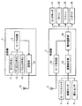
図1は、本発明の実施例1かかるパニックアラームシステムの概要構成を示す概要構成図である。同図に示すように、本実施例1にかかるパニックアラームシステムは、車載警報装置である受信機2と遠隔制御装置である送信機1によって構成される。
FIG. 1 is a schematic configuration diagram illustrating a schematic configuration of a panic alarm system according to a first embodiment of the present invention. As shown in the figure, the panic alarm system according to the first embodiment includes a
送信機1は、ロックボタン11、アンロックボタン12、パニックボタン13、コード作成部14、送信部15およびアンテナ16を備える。
The
ロックボタン11は、受信機2が搭載された車両のドアに対する施錠指示の入力を受け付けるボタンであり、アンロックボタン12は、受信機2が搭載された車両のドアに対する開錠指示の入力を受け付けるボタンである。
The
ユーザ(例えば運転者)は、このロックボタン11、アンロックボタン12の押下操作によって、車両のドアの施錠・開錠を実行する。すなわち、送信機1は、受信機2が搭載された車両のワイヤレスドアロック装置の遠隔操作端末(リモートキー)として機能する。
A user (for example, a driver) locks and unlocks the door of the vehicle by pressing the
さらに、パニックボタン13は、受信機2による警報の強制出力(パニックアラーム)の実行要求を受け付けるボタンである。
Furthermore, the
コード作成部14は、ロックボタン11、アンロックボタン12、パニックボタン13の押下状態をもとに、受信機2に送信する送信コード40を作成する処理部である。送信コード40は、具体的には図2に示すように、IDコード41およびファンクションコード42から構成される(実際は同期コード等が含まれるが、ここでは省略している)。
The
IDコード41は、受信機2が送信機1の識別に用いるコードであり、ファンクションコード42は、送信機1から受信機2へ送信される動作指示、すなわち施錠指令、開錠指令、警報指令を示すコードである。ここで、コード作成部14は、ロックボタン11、アンロックボタン12、パニックボタン13の押下状態に応じて、第1の警報指令(第1パニック)と第2の警報指令(第2パニック)とを作成する。
The
具体的には、コード作成部14は、施錠指令としてファンクションコード「00」を、開錠指令としてファンクションコード「01」を、第1パニックとしてファンクションコード「10」を、第2パニックとしてファンクションコード「11」を作成する。
Specifically, the
送信部15は、コード作成部14が作成した送信コード40を所定の変調方式で変調し、アンテナ16から送信する。
The
受信機2は、アンテナ21、コード受信部22、盗難検出部23および動作選択部24を備えると共に、カーテシスイッチ3、振動センサ4、侵入センサ5、ロックモータ31、ホーン32、サイレン33およびハザード34と接続している。
The
カーテシスイッチ3は、受信機2が搭載された車両のドアに連動し、ドアが開いている状態でオン、ドアが閉じている状態でオフとなる。なお、このカーテシスイッチ3は、車両の複数のドアにそれぞれ対応して設ける。
The courtesy switch 3 is linked to the door of the vehicle on which the
振動センサ4は、車体や窓の振動を検知して受信機2に出力するセンサである。また、侵入センサ5は、超音波などを用いて車両内への不審者の侵入を検出し、検出結果を受信機2に出力する。
The vibration sensor 4 is a sensor that detects the vibration of the vehicle body or the window and outputs it to the
盗難検出部23は、カーテシスイッチ3、振動センサ4、侵入センサ5の出力をもとに、車両からの盗難が発生したか否かを監視し、盗難の発生を検出した場合に動作選択部24に出力する。
The
一方、コード受信部22は、送信機1が送信した送信コード40を、アンテナ21を介して受信し、復調処理およびコード解析処理を実行する。コード解析処理では、まず、受信したIDコード41が受信機2側で記憶しているIDコードと一致するか否かを判定する。その結果、IDコードが一致したならば、ファンクションコード42によって示された指令を受け付ける。
On the other hand, the
動作選択部24は、コード受信部22および盗難検出部23の動作を受けて、ロックモータ31、ホーン32、サイレン33およびハザード34の動作制御を行う。ロックモータ31は、車両のドアロックの開閉を行なうモータであり、動作選択部24は、ロックモータ31の動作制御によってドアの施錠および開錠を行なう。
The
また、ホーン32は、車両の周囲に警告音を発する警音器である。動作選択部24は、このホーン32を鳴らすことで、不審者の撃退を行なう。また、サイレン33は、車両周辺に対して音声出力を行うことで、不審者の撃退を実現する。尚、ホーンを削除し、単一のサイレンで警報音と音声の出力を行なってもよい。
The
ハザード34は、車両の方向指示灯の同時点灯によって、ユーザなどへの情報伝達、例えはドアロックの完了など伝達を行なう。
The
上述したように、送信機1は、第1パニック(ファンクションコード「10」)および第2パニック(ファンクションコード「11」)を送信する。動作選択部24は、この第1パニックと第2パニックに対して、それぞれ異なる警報動作を対応させている。例えば、第1パニックに対してはサイレンを用いた合成音声による警告音声の出力(例えば「車から離れなさい。警察を呼びます。」などの音声出力)を実行し、第2パニックに対してはホーン32による警告音の出力を行なう。
As described above, the
第1パニックに対応する警報動作(第1アラーム)と第2パニックに対応する警報動作(第2アラーム)としては、それぞれ任意の動作を用いることができるが、第1アラームは第2アラームに比して静かなものとする。 Arbitrary actions can be used as the warning action corresponding to the first panic (first alarm) and the warning action corresponding to the second panic (second alarm), respectively, but the first alarm is different from the second alarm. And be quiet.
このように、通常の警報動作に比して静かな警報動作を設け、警報動作の内容をユーザが選択可能な構成とすることで、騒音公害の低減と不審者の撃退とを両立させることができる。 In this way, by providing a quiet alarm operation compared to the normal alarm operation and making the user selectable the content of the alarm operation, it is possible to achieve both reduction of noise pollution and repelling suspicious persons it can.
つぎに、第1パニックを実行する場合と、第2パニックを実行する場合における操作方法について説明する。図3は、パニックボタン13の操作時間によって第1パニックと第2パニックのいずれかを選択する方法について説明する説明図である。
Next, an operation method when executing the first panic and when executing the second panic will be described. FIG. 3 is an explanatory diagram for explaining a method of selecting either the first panic or the second panic according to the operation time of the
具体的には、コード作成部14は、パニックボタン13の押下が2秒未満である場合には第1パニックを選択し、パニックボタン13が2秒以上押下された場合に第2パニックを選択する。
Specifically, the
すなわち、図3−1に示すように、パニックボタン13がオンになった時点で時間の計測を開始し、パニックボタン13がオフになるまでの経過時間T1が「0<T1<2秒」である場合に、第1パニックを選択する。一方、図3−2に示すように、パニックボタン13のオン時間T2が「T2≧2秒」を満足した場合には、第2パニックを選択する。
That is, as shown in FIG. 3A, the time measurement starts when the
すなわち、この選択方法では、パニックボタン13のオン時間が2秒以下の場合はパニックボタン13がオフに戻った時点で第1パニックを選択し、オン時間が2秒を超えるとその時点で第2パニックを選択することとなる。
That is, in this selection method, when the on time of the
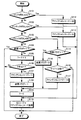
つぎに、コード作成部14、コード受信部22および動作選択部24の処理動作についてそれぞれ説明する。図4は、コード作成部14の処理動作を説明するフローチャートである。この処理フローは、送信機1に電源が投入されている状態で繰り返し実行されるメインルーチンの一部である。
Next, processing operations of the
図4に示すように、まずコード作成部14は、ロックボタン11が押下されている、すなわちオン状態であるか否かを判定する(ステップS101)。その結果、ロックボタン11がオン状態であるならば(ステップS101,Yes)、コード作成部14は、ファンクションコード42を「00」に設定する(ステップS112)。
As shown in FIG. 4, first, the
一方、ロックボタン11がオン状態でないならば(ステップS101,No)、コード作成部14は、アンロックボタン12が押下されている、すなわちオン状態であるか否かを判定する(ステップS102)。
On the other hand, if the
その結果、アンロックボタン12がオン状態であるならば(ステップS102,Yes)、コード作成部14は、ファンクションコート42を「01」に設定する(ステップS113)。
As a result, if the
一方、アンロックボタン12がオン状態でないならば(ステップS102,No)、コード作成部14は、パニックボタン13が押下されている、すなわちオン状態であるか否かを判定する(ステップS103)。
On the other hand, if the
その結果、パニックボタン13がオン状態であるならば(ステップS103,Yes)コード作成部14は送信フラグの値が「1」であるか否かを判定する(ステップS104)。なお、この送信フラグは「0」または「1」のいずれかの値をとり、初期状態の値が「0」である。
As a result, if the
送信フラグの値が「1」でないならば(ステップS104,No)、コード作成部14は、パニックボタン13がオン状態になってからの経過時間Tの値を「1」増加させる(ステップS105)。なお、この経過時間Tは、初期状態での値が「0」である。
If the value of the transmission flag is not “1” (No at Step S104), the
ステップS105終了後、コード作成部14は、経過時間Tが2秒以上であるか否かを判定する(ステップS106)。具体的には、経過時間Tは処理のサイクルによって加算した値であるので、例えば処理の1サイクルが50msであるならば、経過時間Tの値が「40」以上である場合に「T≧2秒」となる。
After step S105, the
ステップS106における判定の結果、経過時間Tが2秒以上であるならば(ステップS106,Yes)、コード作成部14は、ファンクションコード42を「11」に設定して(ステップS107)、送信フラグの値を「1」に設定する(ステップS108)。この送信フラグは「0」または「1」のいずれかの値をとり、初期状態の値が「0」である。
As a result of the determination in step S106, if the elapsed time T is 2 seconds or more (step S106, Yes), the
ところで、ステップS103において、パニックボタン13がオン状態で無いならば(ステップS103,No)、コード作成部14は、送信フラグの値が「1」であるかいなかを判定する(ステップS114)。
By the way, if the
その結果、送信フラグの値が「1」であるならば(ステップS114,Yes)、コード作成部14は送信フラグをリセット、すなわちその値を「0」に設定する(ステップS115)。
As a result, if the value of the transmission flag is “1” (step S114, Yes), the
一方、送信フラグの値が「1」でなければ(ステップS114,No)、コード作成部14は,経過時刻Tが0秒より大きく、かつ2秒未満であるか否かを判定する(ステップS116)。その結果、経過時間Tが0秒より大きく、かつ2秒未満であるならば(ステップS116,Yes)、コード作成部14は、ファンクションコード42を「10」に設定する(ステップS117)。
On the other hand, if the value of the transmission flag is not “1” (No at Step S114), the
ステップS108、ステップS115もしくはステップS117の終了後、コード作成部14は、経過時間Tの値をリセットする(ステップS109)。
After step S108, step S115, or step S117 ends, the
そして、ステップS109、ステップS112もしくはステップS113の終了後、コード作成部14は、送信機1に固有のIDコード41をファンクションコード42に付加して送信コード40を作成し、送信部15によって送信する(ステップS110)。
After step S109, step S112, or step S113, the
ステップS110が終了した場合、ステップS104において送信フラグの値が「1」である場合(ステップS104,Yes)、ステップS106において経過時間Tが2秒未満である場合(ステップS106,No)、ステップS116において経過時間Tが2秒以上もしくは0秒である場合(ステップS106,No)、コード処理部14は、このルーチンを抜ける。
When step S110 ends, when the value of the transmission flag is “1” at step S104 (step S104, Yes), when elapsed time T is less than 2 seconds at step S106 (step S106, No), step S116 When the elapsed time T is 2 seconds or longer or 0 seconds (step S106, No), the
つぎに、図5のフローチャートを参照し、コード受信部22の処理動作を説明する。この処理フローは、受信機2に電源が投入されている状態で繰り返し実行されるメインルーチンの一部である。
Next, the processing operation of the
図5に示すように、まずコード受信部22は、アンテナ21が送信機1からコードを受信したか否かを判定する(ステップS201)。アンテナ21が送信機1からコードを受信したならば(ステップS201,Yes)、コード受信部22は、受信したIDコード41が受信機2側で記憶しているIDコードと一致するか否かを判定する(ステップS202)。
As shown in FIG. 5, the
その結果、IDコードが一致したならば(ステップS202,Yes)、コード受信部22は、ファンクションコード42が「00」、すなわち施錠指令(ロック要求)であるか否かを判定する(ステップS203)。
As a result, if the ID codes match (step S202, Yes), the
その結果、ファンクションコード42が「00」であれば(ステップS203,Yes)、コード受信部22は、ロック要求フラグの値を「1」に設定する(ステップS210)。このロック要求フラグは「0」または「1」のいずれかの値をとり、初期状態の値が「0」である。
As a result, if the
一方、ファンクションコード42が「00」でなければ(ステップS203,No)、コード受信部22は、ファンクションコード42が「01」、すなわち開錠指令(アンロック要求)であるか否かを判定する(ステップS204)。
On the other hand, if the
その結果、ファンクションコード42が「01」であれば(ステップS204,Yes)、コード受信部22は、アンロック要求フラグの値を「1」に設定する(ステップS211)。このアンロック要求フラグは「0」または「1」のいずれかの値をとり、初期状態の値が「0」である。
As a result, if the
一方、ファンクションコード42が「01」でなければ(ステップS204,No)、コード受信部22は、ファンクションコード42が「10」、すなわち第1パニック要求であるか否かを判定する(ステップS205)。
On the other hand, if the
その結果、ファンクションコード42が「10」であれば(ステップS205,Yes)、コード受信部22は、第1パニック要求フラグの値を「1」に設定し(ステップS212)、第2パニック要求フラグの値を「0」に設定する(ステップS213)。この第1パニック要求フラグおよび第2パニック要求フラグはそれぞれ「0」または「1」のいずれかの値をとり、初期状態の値が「0」である。
As a result, if the
一方、ファンクションコード42が「10」でなければ(ステップS205,No)、コード受信部22は、ファンクションコード42が「11」、すなわち第2パニック要求であるか否かを判定する(ステップS206)。
On the other hand, if the
その結果、ファンクションコード42が「11」であれば(ステップS206,Yes)、コード受信部22は、第2パニック要求フラグの値を「1」に設定し(ステップS209)、第1パニック要求フラグの値を「0」に設定する(ステップS208)。
As a result, if the
アンテナ21が送信機1からコードを受信していない場合(ステップS201,No)、IDコードが一致しない場合(ステップS202,No)、ファンクションコード42が「11」でない場合(ステップS206,No)、もしくはステップS208、ステップS213、ステップS211、ステップS210のいずれかが終了した場合、コード受信部22は、このルーチンを抜ける。
When the
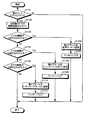
つぎに、図6のフローチャートを参照し、動作選択部24の処理動作を説明する。この処理フローは、受信機2に電源が投入されている状態で繰り返し実行されるメインルーチンの一部である。
Next, the processing operation of the
図6に示すように、まず動作選択部24は、ロック要求フラグの値が「1」であるか否かを判定する(ステップS301)。その結果、ロック要求フラグの値が「1」であるならば(ステップS301,Yes)、動作選択部24は、カーテシスイッチ3の出力をもとに、車両の全てのドアが閉まっているか否かを判定する(ステップS309)。
As shown in FIG. 6, the
その結果、全てのドアが閉まっているならば(ステップS309,Yes)、動作選択部24はロックモータ31を動作させて施錠を実行し(ステップS310)、アームフラグの値を「1」に設定する(ステップS311)。このアームフラグは、盗難検出部23による盗難の自動検出処理を実行するか否かを指定するフラグである。具体的には、アームフラグは「0」または「1」のいずれかの値をとり、値が「0」の場合には盗難検出処理を実行せず、値が「1」の場合には盗難検出処理を実行する。なお、初期状態の値は「0」である。従って本処理フローでは、ロック要求によって車両のドアが施錠された際に、盗難検出処理が自動的に起動することとなる。
As a result, if all the doors are closed (step S309, Yes), the
動作選択部24は、ステップS311の終了後、ロック要求フラグの値を「0」に設定するとともに、ハザード34やホーン32などを用いて施錠の完了をユーザに通知する、いわゆるアンサーバックを実行する(ステップS312)。
After completing step S311, the
また、閉まっていないドアがある場合(ステップS309,No)、動作選択部24は、閉まっていないドアがあるために施錠ができないことを通知するアンサーバックを実行する(ステップS313)。
If there is a door that is not closed (step S309, No), the
一方、ロック要求フラグの値が「1」でないならば(ステップS301,No)、動作選択部24は、アンロック要求フラグの値が「1」であるか否かを判定する(ステップS302)。
On the other hand, if the value of the lock request flag is not “1” (No at Step S301), the
その結果、アンロック要求フラグの値が「1」であるならば(ステップS302,Yes)、動作選択部24は、ロックモータ31を動作させて開錠を実行し(ステップS314)、アームフラグの値を「0」に設定した(ステップS315)後、ハザード34やホーン32などを用いて開錠の完了をユーザに通知するアンサーバックを行う(ステップS316)。
As a result, if the value of the unlock request flag is “1” (step S302, Yes), the
一方、アンロック要求フラグの値が「1」でないならば(ステップS302,No)、動作選択部24は、つぎに第1パニック要求フラグの値が「1」であるか否かを判定する(ステップS303)。
On the other hand, if the value of the unlock request flag is not “1” (No in step S302), the
その結果、第1パニック要求フラグの値が「1」であるならば(ステップS303,Yes)、動作選択部24は、第1アラームフラグの値を「1」に設定するとともに、第2アラームフラグの値を「0」に設定する(ステップS317)。この第1アラームフラグおよび第2アラームフラグはそれぞれ「0」または「1」のいずれかの値をとり、初期状態の値が「0」である。
As a result, if the value of the first panic request flag is “1” (step S303, Yes), the
一方、第1パニック要求フラグの値が「1」でないならば(ステップS303,No)、動作選択部24は、つぎに第2パニック要求フラグの値が「1」であるか否かを判定する(ステップS304)。
On the other hand, if the value of the first panic request flag is not “1” (No in step S303), the
その結果、第2パニック要求フラグの値が「1」であるならば(ステップS304,Yes)、動作選択部24は、第1アラームフラグの値を「0」に設定するとともに、第2アラームフラグの値を「1」に設定する(ステップS318)。
As a result, if the value of the second panic request flag is “1” (step S304, Yes), the
第2パニック要求フラグの値が「1」でない場合(ステップS304,No)、もしくはステップS312、ステップS313、ステップS316、ステップS317、ステップS318のいずれかが終了した場合、動作選択部24はアームフラグの値が「1」であるか否かを判定する(ステップS305)。
When the value of the second panic request flag is not “1” (No at Step S304), or when any of Step S312, Step S313, Step S316, Step S317, and Step S318 ends, the
その結果、アームフラグの値が「1」であるならば(ステップS305,Yes)、動作選択部24は、盗難検出部23が盗難を検出したか否かを判定する(ステップS306)。
As a result, if the value of the arm flag is “1” (step S305, Yes), the
その結果、盗難検出部23が盗難を検出したならば(ステップS306,Yes)、動作選択部24は、第1アラームフラグの値を「0」に設定するとともに、第2アラームフラグの値を「1」に設定する(ステップS307)。
As a result, if the
アームフラグの値が「1」でない場合(ステップS305,No)、盗難検出部23が盗難を検出していない場合(ステップS306,No)、もしくはステップS307が終了した場合、動作選択部24は、このルーチンを抜ける。
When the value of the arm flag is not “1” (No at Step S305), when the
つぎに、図7のフローチャートを参照し、動作選択部24における警報動作を説明する。この処理フローは、受信機2に電源が投入されている状態で繰り返し実行されるメインルーチンの一部である。
Next, the alarm operation in the
図7に示すように、まず動作選択部24は、第1アラームフラグの値が「1」であるか否かを判定し(ステップS401)、その結果、第1アラームフラグの値が「1」であるならば(ステップS401,Yes)、動作選択部24は第1アラームである警告音声の出力を実行し、第1アラームフラグの値を「0」に設定する(ステップS402)。
As shown in FIG. 7, the
一方、第1アラームフラグの値が「1」でないならば(ステップS401,No)、動作選択部24は、第2アラームフラグの値が「1」であるか否かを判定する(ステップS404)。
On the other hand, if the value of the first alarm flag is not “1” (No in step S401), the
その結果、第2アラームフラグの値か「1」であるならば(ステップS404,Yes)、動作選択部24は第2アラームであるホーン32からの警告音出力を実行し、第2アラームフラグの値を「0」に設定する(ステップS405)。
As a result, if the value of the second alarm flag is “1” (step S404, Yes), the
第2アラームフラグの値が「1」でない場合(ステップS404,No)、もしくはステップS402とステップS405のいずれかが終了した場合、動作選択部24は、このルーチンを抜ける。
When the value of the second alarm flag is not “1” (No at Step S404), or when one of Step S402 and Step S405 ends, the
図3〜図7によって説明したように、送信機1は、パニックボタン13を押下する時間の長さによって第1パニックと第2パニックとを選択的に指定し、受信機2にそれぞれ異なった警報動作を実行させる。また、第1パニックに対応する第1アラームを第2パニックに対応する第2アラームに比して静かな警報動作とするとともに、第2アラームを盗難検出の警報と共用している。
As described with reference to FIGS. 3 to 7, the
ところで、図3および図4では、パニックボタン13のオン時間が2秒以上か否かに応じて第1パニックと第2パニックとのいずれを選択するかを決定していたが、第1パニックと第2パニックとの選択方法はこの方法に限定されるものではない。
By the way, in FIG. 3 and FIG. 4, it was determined whether to select the first panic or the second panic depending on whether the on time of the
例えば、パニックボタン13がオンになった時点で第1パニックを選択してファンクションコードの作成・送信を開始し、パニックボタン13がオンになってから所定時間(例えば2秒)経過した時点で第1パニックから第2パニックに切替えるようにしてもよい。この場合、受信機2側の警報動作も、まず第1アラームを実行し、その後、第2アラームに切替わることとなる。
For example, when the
図8は、パニックボタン13の操作開始時点でファンクションコードを作成・送信する場合の操作について説明する説明図である。図8−1に示すように、パニックボタン13がオンになった時点で、ファンクションコード「10」の作成・送信を開始するとともに、時間の計測を開始する。そして、パニックボタン13がオフになるまでの経過時間T1が「0<T1<2秒」である場合、ファンクションコード「10」のみが作成・送信されることとなる。
FIG. 8 is an explanatory diagram for explaining an operation in the case where a function code is created / transmitted when the operation of the
一方、図8−2に示すように、パニックボタン13がオフになるまでの経過時間T2が「T2≧2秒」である場合、経過時間2秒の時点でファンクションコード「10」の作成を終了し、ファンクションコード「11」を作成・送信する。
On the other hand, as shown in FIG. 8B, when the elapsed time T2 until the
パニックボタン13の操作開始時点でファンクションコードを作成・送信する場合のコード作成部14の処理動作を図9のフローチャートを参照して説明する。この処理フローは、送信機1に電源が投入されている状態で繰り返し実行されるメインルーチンの一部である。
The processing operation of the
図9に示すように、まずコード作成部14は、ロックボタン11が押下されている、すなわちオン状態であるか否かを判定する(ステップS501)。その結果、ロックボタン11がオン状態であるならば(ステップS501,Yes)、コード作成部14は、ファンクションコード42を「00」に設定する(ステップS510)。
As shown in FIG. 9, first, the
一方、ロックボタン11がオン状態でないならば(ステップS501,No)、コード作成部14は、アンロックボタン12が押下されている、すなわちオン状態であるか否かを判定する(ステップS502)。
On the other hand, if the
その結果、アンロックボタン12がオン状態であるならば(ステップS502,Yes)、コード作成部14は、ファンクションコート42を「01」に設定する(ステップS511)。
As a result, if the
一方、アンロックボタン12がオン状態でないならば(ステップS502,No)、コード作成部14は、パニックボタン13が押下されている、すなわちオン状態であるか否かを判定する(ステップS503)。
On the other hand, if the
その結果、パニックボタン13がオン状態で無いならば(ステップS503,No)、コード作成部14は、経過時間Tの値をリセットする(ステップS512)。一方、パニックボタン13がオン状態であるならば(ステップS503,Yes)、コード作成部14は、パニックボタン13がオン状態になってからの経過時間Tの値を「1」増加させる(ステップS504)。
As a result, if the
ステップS504終了後、コード作成部14は、経過時間Tが2秒以上であるか否かを判定し(ステップS505)、経過時間Tが2秒以上であるならば(ステップS505,Yes)、コード作成部14は、ファンクションコード42を「11」に設定する(ステップS506)。一方、経過時間Tが2秒未満であるならば(ステップS505,No)、コード作成部14は、ファンクションコード42を「10」に設定する(ステップS507)。
After step S504, the
そして、ステップS506、ステップS507、ステップS510もしくはステップS511の終了後、コード作成部14は、送信機1に固有のIDコード41をファンクションコード42に付加して送信コード40を作成し、送信部15によって送信する(ステップS508)。
After step S506, step S507, step S510, or step S511, the
ステップS508が終了した場合、もしくはステップS512が終了した場合、コード処理部14は、このルーチンを抜ける。
When step S508 ends or when step S512 ends, the
この図9に示した処理フローを送信機1が用いる場合であっても、受信機2側の処理は上述の処理フロー(図5〜図7)を利用することができる。但し、この場合、送信機のパニックボタンを押し続けると、2秒を経過した時点で第1パニックが第2パニックに切り換わるため、第1パニックによる音声警告が途中で途切れることになる。これを防ぐ場合は、少なくとも1フレーズ分は第1パニック警報を出力した後に第2パニック警報に切替えればよい(図7のステップS404で「Yes」と判定した後、警告音声が出力中であれば、その1フレーズが終了するまでステップS405をパスさせる)。
Even when the
ところで、パニックアラームとして用いる第2アラームは、必ずしも盗難の自動検出時の警報と共用する必要はなく、盗難の自動検出時の警報動作(メインアラーム)を独自に設定してもよい。 By the way, the second alarm used as the panic alarm is not necessarily shared with the alarm at the time of automatic detection of the theft, and the alarm operation (main alarm) at the time of the automatic detection of the theft may be set independently.
図10は、盗難の自動検出時の警報動作(メインアラーム)を独自に設定した場合の動作選択部24の処理動作を示すフローチャートである。このフローチャートは、盗難を検出した場合の処理(ステップS607)が異なり、第2アラームフラグのセットに替えて独自の第3アラームフラグのセットを行なっている。他の処理については図6に示したフローチャートと同様であるので、ここでは説明を省略する。
FIG. 10 is a flowchart showing the processing operation of the
また、図11は、メインアラームを独自に設定した場合における動作選択部24の警報動作を説明するフローチャートである。この処理フローは、受信機2に電源が投入されている状態で繰り返し実行されるメインルーチンの一部である。
FIG. 11 is a flowchart for explaining the alarm operation of the
図11に示すように、まず動作選択部24は、第3アラームフラグの値が「1」であるか否かを判定し(ステップS701)、その結果、第3アラームフラグの値が「1」であるならば(ステップS701,Yes)、第1優先として第3アラームを実行し、第3アラームフラグの値を「0」に設定する(ステップS702)。
As shown in FIG. 11, first, the
一方、第3アラームフラグの値が「1」でないならば(ステップS701,No)、動作選択部24は、第1アラームフラグの値が「1」であるか否かを判定する(ステップS704)。
On the other hand, if the value of the third alarm flag is not “1” (step S701, No), the
その結果、第1アラームフラグの値が「1」であるならば(ステップS704,Yes)、動作選択部24は第1アラームを実行し、第1アラームフラグの値を「0」に設定する(ステップS705)。
As a result, if the value of the first alarm flag is “1” (Yes in step S704), the
一方、第1アラームフラグの値が「1」でないならば(ステップS704,No)、動作選択部24は、第2アラームフラグの値が「1」であるか否かを判定する(ステップS706)。
On the other hand, if the value of the first alarm flag is not “1” (step S704, No), the
その結果、第2アラームフラグの値か「1」であるならば(ステップS706,Yes)、動作選択部24は第2アラームを実行し、第2アラームフラグの値を「0」に設定する(ステップS405)。
As a result, if the value of the second alarm flag is “1” (step S706, Yes), the
第2アラームフラグの値が「1」でない場合(ステップS404,No)、もしくはステップS702,ステップS705,ステップS707のいずれかが終了した場合、動作選択部24は、このルーチンを抜ける。
When the value of the second alarm flag is not “1” (step S404, No), or when any of step S702, step S705, and step S707 ends, the
つぎに、第1パニックと第2パニックとの選択方法のバリエーションについて、さらに説明する。第1パニックと第2パニックとの選択方法には、大別すると、送信機側で第1パニックと第2パニックに対応する異なるファンクションコードを作成する方法と、受信機側で第1パニックと第2パニックとを選択する方法がある。 Next, variations of the selection method between the first panic and the second panic will be further described. The selection method of the first panic and the second panic can be broadly divided into a method of creating different function codes corresponding to the first panic and the second panic on the transmitter side, and a first panic and a second panic on the receiver side. There is a method of selecting two panics.
まず、送信機側で第1パニックと第2パニックに対応する異なるファンクションコードを作成する方法としては、第1パニックに対応する操作ボタンと第2パニックに対応する操作ボタンとをそれぞれ設ける方法がある。この場合、第1パニックボタンと第2パニックボタンのいずれかが操作されると、対応するファンクションコードを直ちに送信することができる。 First, as a method of creating different function codes corresponding to the first panic and the second panic on the transmitter side, there is a method of providing an operation button corresponding to the first panic and an operation button corresponding to the second panic, respectively. . In this case, when either the first panic button or the second panic button is operated, the corresponding function code can be transmitted immediately.
また、送信機側にパニックボタンに替えてシフトボタンを設け、このシフトホタンと他のボタンが同時に操作された場合に、第1パニックと第2パニックのいずれかに対応するファンクションコードを送信する方法もある。例えば、ロックボタンとシフトボタンとが同時に操作された場合に第1パニックに対応するファンクションコードを送信し、アンロックボタンとシフトボタンとが同時に操作された場合に第2パニックに対応するファンクションコードを送信すればよい。 There is also a method of transmitting a function code corresponding to either the first panic or the second panic when a shift button is provided instead of the panic button on the transmitter side and this shift button and another button are operated simultaneously. is there. For example, a function code corresponding to the first panic is transmitted when the lock button and the shift button are operated simultaneously, and a function code corresponding to the second panic is transmitted when the unlock button and the shift button are operated simultaneously. Just send it.
また、送信機側にパニックボタンに替えてシフトボタンを設け、シフトボタンと他のボタンとが同時に操作された時間によって、第1パニックと第2パニックのいずれかに対応するファンクションコードを送信する方法もある。例えば、ロックボタンとシフトボタンとが同時に、2秒未満操作された場合には第1パニックに対応するファンクションコードを送信し、ロックボタンとシフトボタンとが同時に、2秒以上操作された場合に第2パニックに対応するファンクションコードを送信すればよい。 A method of transmitting a function code corresponding to either the first panic or the second panic according to the time when the shift button and another button are operated simultaneously is provided with a shift button instead of the panic button on the transmitter side. There is also. For example, when the lock button and the shift button are simultaneously operated for less than 2 seconds, a function code corresponding to the first panic is transmitted, and when the lock button and the shift button are simultaneously operated for 2 seconds or more, the first function code is transmitted. A function code corresponding to two panics may be transmitted.
また、他の機能を有するボタンを所定時間以上押した場合に、第1パニックと第2パニックのいずれかに対応するファンクションコードを送信する方法もある。例えば、ロックボタンがオン状態になった場合に直ちにロック要求を送信し、ロックボタンが2秒以上4秒未満の間オン状態となった場合に第1パニックに対応するファンクションコードを送信し、ロックボタンが4秒以上オン状態となった場合に第2パニックに対応するファンクションコードを送信すればよい。 There is also a method of transmitting a function code corresponding to either the first panic or the second panic when a button having another function is pressed for a predetermined time or more. For example, a lock request is immediately sent when the lock button is turned on, and a function code corresponding to the first panic is sent when the lock button is turned on for more than 2 seconds and less than 4 seconds. What is necessary is just to transmit the function code corresponding to a 2nd panic when a button will be in an ON state for 4 seconds or more.
他にも、ロックボタン、アンロックボタンや他のボタン、シフトボタンなどの所定時間内の操作回数やその組み合わせによって第1パニックと第2パニックのいずれかに対応するファンクションコードを送信してもよい。 In addition, a function code corresponding to either the first panic or the second panic may be transmitted depending on the number of operations within a predetermined time such as a lock button, an unlock button, another button, a shift button, or a combination thereof. .
つぎに、受信機側で第1パニックと第2パニックとを選択する方法としては、送信機からパニック要求を示す単一のファンクションコードを受信し、その受信時間によって第1パニックと第2パニックとのいずれかを選択する方法がある。例えば、パニック要求を示すファンクションコードの受信時間が2秒以下であれば第1パニックを選択し、受信時間が2秒以上であれば第2パニックを選択すればよい。 Next, as a method of selecting the first panic and the second panic on the receiver side, a single function code indicating a panic request is received from the transmitter, and the first panic and the second panic are received according to the reception time. There is a way to choose either. For example, the first panic may be selected if the reception time of the function code indicating the panic request is 2 seconds or less, and the second panic may be selected if the reception time is 2 seconds or more.
この方法において、送信機側は、パニック要求を指示するファンクションコードを作成するために専用のパニックボタンを設けてもよいし、他のボタンとシフトボタン、例えばロックボタンとシフトボタンとを同時に操作した場合にパニック要求を指示するファンクションコードを作成する構成としてもよい。 In this method, the transmitter side may be provided with a dedicated panic button for creating a function code for instructing a panic request, or another button and a shift button, for example, a lock button and a shift button are operated simultaneously. In some cases, a function code for instructing a panic request may be created.
この方法を用いる場合の動作選択部24の処理動作を図12のフローチャートに示す。同図に示すように、まず動作選択部24は、ロック要求フラグの値が「1」であるか否かを判定する(ステップS801)。その結果、ロック要求フラグの値が「1」であるならば(ステップ801,Yes)、動作選択部24は、カーテシスイッチ3の出力をもとに、車両の全てのドアが閉まっているか否かを判定する(ステップS812)。
The processing operation of the
その結果、全てのドアが閉まっているならば(ステップS812,Yes)、動作選択部24はロックモータ31を動作させて施錠を実行し(ステップS813)、アームフラグの値を「1」に設定する(ステップS814)。
As a result, if all the doors are closed (step S812, Yes), the
動作選択部24は、ステップS814の終了後、ロック要求フラグの値を「0」に設定するとともに、ハザード34やホーン32などを用いて施錠の完了をユーザに通知するアンサーバックを実行する(ステップS815)。
The
また、閉まっていないドアがある場合(ステップS812,No)、動作選択部24は、閉まっていないドアがあるために施錠ができないことを通知するアンサーバックを実行する(ステップS816)。
If there is a door that is not closed (step S812, No), the
一方、ロック要求フラグの値が「1」でないならば(ステップS801,No)、動作選択部24は、アンロック要求フラグの値が「1」であるか否かを判定する(ステップS802)。
On the other hand, if the value of the lock request flag is not “1” (No in step S801), the
その結果、アンロック要求フラグの値が「1」であるならば(ステップS802,Yes)、動作選択部24は、ロックモータ31を動作させて開錠を実行し(ステップS817)、アームフラグの値を「0」に設定した(ステップS818)後、ハザード34やホーン32などを用いて開錠の完了をユーザに通知するアンサーバックを行う(ステップS819)。
As a result, if the value of the unlock request flag is “1” (step S802, Yes), the
一方、アンロック要求フラグの値が「1」でないならば(ステップS802,No)、動作選択部24は、つぎにパニック要求フラグの値が「1」であるか否かを判定する(ステップS803)。その結果、パニック要求フラグの値が「1」でない場合(ステップS803,No)、動作選択部24は経過時刻Tの値をリセットする(ステップS820)。
On the other hand, if the value of the unlock request flag is not “1” (step S802, No), the
一方、パニック要求フラグの値が「1」であるならば(ステップS803,Yes)、動作選択部24は、パニック要求フラグが「1」になってからの経過時間Tの値を「1」増加させる(ステップS804)。
On the other hand, if the value of the panic request flag is “1” (step S803, Yes), the
ステップS804終了後、動作選択部24は、経過時間Tが2秒以上であるか否かを判定する(ステップS805)。経過時間Tが2秒以上であるならば(ステップS805,Yes)、動作選択部24は、第1アラームフラグの値を「0」に設定するとともに、第2アラームフラグの値を「1」に設定する(ステップS807)。
After step S804 ends, the
一方、経過時間Tが2秒未満であるならば(ステップS805,No)、動作選択部24は、第1アラームフラグの値を「1」に設定するとともに、第2アラームフラグの値を「0」に設定する(ステップS806)。
On the other hand, if the elapsed time T is less than 2 seconds (step S805, No), the
ステップS806、ステップS807、ステップS820、ステップS817、ステップS816、ステップS815のいずれかが終了した場合、動作選択部24はアームフラグの値が「1」であるか否かを判定する(ステップS808)。
When any of Step S806, Step S807, Step S820, Step S817, Step S816, and Step S815 is completed, the
その結果、アームフラグの値が「1」であるならば(ステップS808,Yes)、動作選択部24は、盗難検出部23が盗難を検出したか否かを判定する(ステップS809)。
As a result, if the value of the arm flag is “1” (step S808, Yes), the
その結果、盗難検出部23が盗難を検出したならば(ステップS809,Yes)、動作選択部24は、第3アラームフラグの値を「1」に設定する(ステップS810)。
As a result, if the
アームフラグの値が「1」でない場合(ステップS808,No)、盗難検出部23が盗難を検出していない場合(ステップS809,No)、もしくはステップS810が終了した場合、動作選択部24は、このルーチンを抜ける。
When the value of the arm flag is not “1” (step S808, No), when the
また、受信機側で第1パニックと第2パニックのいずれかを選択する他の方法としては、送信機から複数のファンクションコードを同時に受信し、その組み合わせによって第1パニックと第2パニックとのいずれかを選択する方法がある。 As another method for selecting either the first panic or the second panic on the receiver side, a plurality of function codes are simultaneously received from the transmitter, and a combination of the first panic and the second panic is received. There is a way to choose.
例えば、送信機側にロックボタン、アンロックボタン、シフトボタンを設け、それぞれのボタンを操作した場合に対応するファンクションコードが送信されるとすると、ロックに対応するファンクションコードとシフトに対応するファンクションコードとを同時に受信した場合に第1パニックを選択し、アンロックに対応するファンクションコードとシフトに対応するファンクションコードとを同時に受信した場合に第2パニックを選択することができる。 For example, when a lock button, unlock button, and shift button are provided on the transmitter side and the corresponding function code is transmitted when each button is operated, the function code corresponding to the lock and the function code corresponding to the shift are transmitted. Can be selected at the same time, and the second panic can be selected when the function code corresponding to unlock and the function code corresponding to shift are received simultaneously.
また、送信機から受信したファンクションコードの組み合わせと、ファンクションコードの受信時間とを用いて第1パニックと第2パニックとのいずれかを選択してもよい。例えば、ロックに対応するファンクションコードとシフトに対応するファンクションコードとを同時に、2秒未満受信した場合に第1パニックを選択し、ロックに対応するファンクションコードとシフトに対応するファンクションコードとを同時に、2秒以上受信した場合に第2パニックを選択することができる。 Moreover, you may select either 1st panic and 2nd panic using the combination of the function code received from the transmitter, and the reception time of the function code. For example, when the function code corresponding to the lock and the function code corresponding to the shift are simultaneously received for less than 2 seconds, the first panic is selected, and the function code corresponding to the lock and the function code corresponding to the shift are simultaneously selected. The second panic can be selected when received for 2 seconds or longer.
また、送信機から受信した他のファンクションコードと、その受信時間とを用いて第1パニックと第2パニックとのいずれかを選択してもよい。例えば、ロックに対応するファンクションコードを受信した時点で直ちにロック要求フラグをセットし、ロックに対応するファンクションコードを2秒以上4秒未満受信した場合に第1パニック要求フラグをセットし、ロックに対応するファンクションコードを4秒以上受信した場合に第2パニック要求フラグをセットすることで、第1パニックと第2パニックとを選択することができる。 Moreover, you may select either 1st panic and 2nd panic using the other function code received from the transmitter, and its reception time. For example, when a function code corresponding to a lock is received, the lock request flag is set immediately. When a function code corresponding to a lock is received for 2 seconds or more and less than 4 seconds, the first panic request flag is set to support the lock. When the function code to be received is received for 4 seconds or more, the first panic and the second panic can be selected by setting the second panic request flag.
他にも、各種ファンクションコードなどの所定時間内の操作回数やその組み合わせ、受信時間など、他の方法で第1パニックと第2パニックとを選択する構成としてもよい。 In addition, the first panic and the second panic may be selected by other methods such as the number of operations within a predetermined time such as various function codes, a combination thereof, and a reception time.
上述してきたように、本実施例1にかかるパニックアラームシステムでは、簡易な構成と操作で複数の警報動作から任意の警報動作を選択することができる。さらに、音声による警報や、通常に比して短い時間のホーン出力を選択することにより、騒音公害を低減しつつ不審者の撃退を実現することができる。 As described above, in the panic alarm system according to the first embodiment, an arbitrary alarm operation can be selected from a plurality of alarm operations with a simple configuration and operation. Further, by selecting a warning by voice or a horn output that is shorter than usual, it is possible to repel a suspicious person while reducing noise pollution.
尚、他の実施形態として、第2パニック指令を受信した場合、動作選択部24が故意にカーテシスイッチ3やセンサ4,5をオンにすることで擬似盗難状態を発生させ、メインアラームを出力させるようにしてもよい。
As another embodiment, when the second panic command is received, the
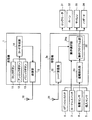
本実施例2では、複数の警報動作について、その動作内容をプログラム可能としたパニックアラームシステムについて説明する。図13は、本発明の実施例2にかかるパニックアラームシステムの概要構成を示す概要構成図である。 In the second embodiment, a panic alarm system in which the operation contents of a plurality of alarm operations can be programmed will be described. FIG. 13 is a schematic configuration diagram illustrating a schematic configuration of the panic alarm system according to the second embodiment of the present invention.
同図に示すように、本実施例2にかかるパニックアラームシステムは、車載警報装置である受信機2aと遠隔制御装置である送信機1によって構成される。受信機2aは、イグニッションスイッチ6に接続される。また、受信機2a内部の動作選択部24aは、実施例1に示した動作選択部24と同様の機能に加え、その内部に動作プログラム部25を有する。その他の構成および動作については、実施例1と同様であるので、同一の構成要素には同一の符号を付して説明を省略する。
As shown in the figure, the panic alarm system according to the second embodiment includes a
イグニッションスイッチ6は、車両のイグニッションキーによってオン/オフ制御されるスイッチである。動作選択部24aは、イグニッションスイッチ6の状態とコード受信部22におけるコード受信状態とが所定の条件を満たした場合に、動作プログラム部25を起動する。
The
動作プログラム部25は、カーテシスイッチ3などの操作手段の入力によって、各種アラームの動作内容を変更する。
The
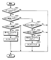
図14は、動作選択部24aによる動作プログラム部25の起動処理について説明するフローチャートである。この処理フローは、受信機2aに電源が投入されている状態で繰り返し実行されるメインルーチンの一部である。
FIG. 14 is a flowchart for explaining the activation process of the
図14に示すように、まず動作選択部24aは、イグニッションスイッチ6がオン状態であるか否かを判定する(ステップS901)。その結果、イグニッションスイッチ6がオン状態であるならば(ステップS901,Yes)、動作選択部24aはロック要求フラグの値が「1」であるか否かを判定する(ステップS902)。
As shown in FIG. 14, the
ロック要求フラグの値が「1」である場合(ステップS902,Yes)、動作選択部24aは、ロック要求フラグが「1」である状態が2秒以上継続したか否かを判定する(ステップS903)。
When the value of the lock request flag is “1” (step S902, Yes), the
ロック要求フラグが「1」である状態が2秒以上継続した場合(ステップS903,Yes)、動作選択部24aは、第1アラームプログラムフラグの値を「1」に設定して(ステップS904)、第1アラームの書き換えを実行することをユーザに通知するアンサーバックを実行する(ステップS905)。ここで、第1アラームフラグは、第1アラームの書き換えを動作プログラム部25に指示するフラグであり、「0」または「1」のいずれかの値をとる。また、初期状態の値は「0」である。
When the state where the lock request flag is “1” continues for 2 seconds or more (step S903, Yes), the
一方、ロック要求フラグの値が「1」ではない場合(ステップS902,No)、動作選択部24aは、アンロック要求フラグの値が「1」であるか否かを判定する(ステップS907)。
On the other hand, when the value of the lock request flag is not “1” (step S902, No), the
アンロック要求フラグの値が「1」である場合(ステップS907,Yes)、動作選択部24aは、アンロック要求フラグが「1」である状態が2秒以上継続したか否かを判定する(ステップS908)。
When the value of the unlock request flag is “1” (step S907, Yes), the
アンロック要求フラグが「1」である状態が2秒以上継続した場合(ステップS908,Yes)、動作選択部24aは、第2アラームプログラムフラグの値を「1」に設定して(ステップS909)、第2アラームの書き換えを実行することをユーザに通知するアンサーバックを実行する(ステップS910)。ここで、第2アラームフラグは、第2アラームの書き換えを動作プログラム部25に指示するフラグであり、「0」または「1」のいずれかの値をとる。また、初期状態の値は「0」である。
When the state where the unlock request flag is “1” continues for 2 seconds or more (step S908, Yes), the
ロック要求フラグが「1」である状態の継続時間が2秒未満である場合(ステップS903,No)、アンロック要求フラグが「1」である状態の継続時間が2秒未満である場合(ステップS908,No)、アンロック要求フラグの値が「1」ではない場合(ステップS907,No)、イグニッションスイッチ6がオフである場合(ステップS901,No)、もしくはステップS905とステップS910のいずれかが終了した場合、動作選択部24aは、このルーチンを抜ける。
When the duration of the state where the lock request flag is “1” is less than 2 seconds (step S903, No), or when the duration of the state where the unlock request flag is “1” is less than 2 seconds (step S903) S908, No), if the value of the unlock request flag is not “1” (No in Step S907), if the
このように、本実施例おいて動作選択部24aは、イグニッションスイッチ6がオンの状態で、ロック要求が2秒以上行なわれた場合に、動作プログラム部25に第1アラームの警報の書き換えを実行させ、イグニッションスイッチ6がオンの状態で、アンロック要求が2秒以上行なわれた場合に、第2アラームの警報の書き換えを動作プログラム部25に実行させる。
Thus, in this embodiment, the
つぎに、動作プログラム部25の処理動作について説明する。図15は、動作プログラム部25の処理動作を説明するフローチャートである。同図に示す処理フローは、受信部2aに電源が投入されている状態で繰り返し実行されるメインルーチンの一部である。
Next, the processing operation of the
まず、動作プログラム部25は、第1アラームプログラムフラグの値が「1」であるか否かを判定する(ステップS1001)。その結果、第1アラームプログラムフラグの値が「1」でないならば(ステップS1001,No)、動作プログラム部25は、第2アラームのプログラム処理を実行する(ステップS1006)。
First, the
一方、第1アラームプログラムフラグの値が「1」であるならば(ステップS1001,Yes)、動作プログラム部25は、カーテシスイッチ3の出力をもとに、所定時間内、例えば10秒以内のドアの開閉回数を検出する(ステップS1002)。その後、ドアの開閉が1回行なわれたか否かを判定する(ステップS1003)。
On the other hand, if the value of the first alarm program flag is “1” (step S <b> 1001, Yes), the
その結果、ドアの開閉が1回行なわれているならば(ステップS1003,Yes)、動作プログラム部25は、第1アラームを音声モード、すなわちサイレン33からの合成音声出力による警報動作に設定し(ステップS1007)、第1アラームを音声モードに設定したことをユーザに通知するアンサーバックを実行し、第1アラームプログラムフラグをクリアする(ステップS1008)。
As a result, if the door is opened and closed once (step S1003, Yes), the
一方、ドアの開閉が1回でなければ(ステップS1003,No)、動作プログラム部25は、ドアの開閉が2回行なわれたか否かを判定する(ステップS1004)。その結果、ドアの開閉が2回行なわれているならば(ステップS1004,Yes)、動作プログラム部25は、第1アラームを2秒のホーンモード、すなわちホーン32から警告音を2秒間出力する警報動作に設定し(ステップS1009)、第1アラームを2秒のホーンモードに設定したことをユーザに通知するアンサーバックを実行し、第1アラームプログラムフラグをクリアする(ステップS1010)。
On the other hand, if the door is not opened and closed once (step S1003, No), the
一方、ドアの開閉が2回でなければ(ステップS1004,No)、動作プログラム部25は、ドアの開閉が3回行なわれたか否かを判定する(ステップS1005)。その結果、ドアの開閉が3回行なわれているならば(ステップS1005,Yes)、動作プログラム部25は、第1アラームをレギュラーアラーム、すなわち盗難検出時と同一の警報動作に設定し(ステップS1011)、第1アラームをレギュラーアラームに設定したことをユーザに通知するアンサーバックを実行し、第1アラームプログラムフラグをクリアする(ステップS1012)。
On the other hand, if the door is not opened and closed twice (step S1004, No), the
ここで、盗難検出時の警報動作(レギュラーアラーム)とは、例えばホーン32を60秒間鳴らす警報動作である。
Here, the alarm operation (regular alarm) at the time of theft detection is an alarm operation for sounding the
ドアの開閉が3回でない場合(ステップS1005,No)、もしくはステップS1006、ステップS1008、ステップS1010、ステップS1012のいずれかが終了した場合、動作プログラム部25は、このルーチンを抜ける。
When the door is not opened and closed three times (step S1005, No), or when any of step S1006, step S1008, step S1010, and step S1012 is completed, the
つぎに、図15に示した第2アラームのプログラム処理(ステップS1006)について、さらに説明する。図16は、第2アラームのプログラム処理について説明するフローチャートである。 Next, the second alarm program process (step S1006) shown in FIG. 15 will be further described. FIG. 16 is a flowchart for explaining the program processing of the second alarm.
同図に示すように、動作プログラム部25は、まず、第2アラームプログラムフラグの値が「1」であるか否かを判定する(ステップS1101)。その結果、第2アラームプログラムフラグの値が「1」であるならば(ステップS1101,Yes)、動作プログラム部25は、カーテシスイッチ3の出力をもとに、所定時間内、例えば10秒以内のドアの開閉回数を検出する(ステップS1102)。その後、ドアの開閉が1回行なわれたか否かを判定する(ステップS1103)。
As shown in the figure, the
その結果、ドアの開閉が1回行なわれているならば(ステップS1103,Yes)、動作プログラム部25は、第2アラームを音声モードに設定し(ステップS1106)、第2アラームを音声モードに設定したことをユーザに通知するアンサーバックを実行する(ステップS1107)と共に第2アラームプログラムフラグをクリアする。
As a result, if the door is opened and closed once (step S1103, Yes), the
一方、ドアの開閉が1回でなければ(ステップS1103,No)、動作プログラム部25は、ドアの開閉が2回行なわれたか否かを判定する(ステップS1104)。その結果、ドアの開閉が2回行なわれているならば(ステップS1104,Yes)、動作プログラム部25は、第2アラームを2秒のホーンモードに設定し(ステップS1108)、第2アラームを2秒のホーンモードに設定したことをユーザに通知するアンサーバックを実行すると共に第2アラームプログラムフラグをクリアする(ステップS1109)。
On the other hand, if the door is not opened and closed once (step S1103, No), the
一方、ドアの開閉が2回でなければ(ステップS1104,No)、動作プログラム部25は、ドアの開閉が3回行なわれたか否かを判定する(ステップS1105)。その結果、ドアの開閉が3回行なわれているならば(ステップS1105,Yes)、動作プログラム部25は、第2アラームをレギュラーアラームに設定し(ステップS1110)、第2アラームをレギュラーアラームに設定したことをユーザに通知するアンサーバックを実行すると共に第2アラームプログラムフラグをクリアする(ステップS1111)。
On the other hand, if the door is not opened and closed twice (step S1104, No), the
ドアの開閉が3回でない場合(ステップS1105,No)、第2アラームプログラムフラグの値が「1」でない場合(ステップS1102,No)、もしくはステップS1107、ステップS1109、ステップS1111のいずれかが終了した場合、第2アラームのプログラム処理を終了する。 When the door is not opened and closed three times (step S1105, No), when the value of the second alarm program flag is not “1” (step S1102, No), or any of step S1107, step S1109, or step S1111 is completed. If so, the program processing of the second alarm is terminated.
このように、動作プログラム部25は、カーテシスイッチ3の出力を利用し、ドアの連続した開閉回数によって第1アラームおよび第2アラームの警報動作を変更することができる。ここで、ドアの開閉回数の検出については、開閉動作が行なわれた後、所定時間以内に再度開閉動作が行なわれた場合に、開閉回数を加算すればよい。
In this manner, the
また、ここではイグニッションスイッチ6を警報動作のプログラム処理の起動に利用し、カーテシスイッチ3を警報動作の特定に使用しているが、専用の操作手段を設けたり、他の操作手段を利用してもよい。
In this example, the
ところで、これまでの説明では複数のパニックアラームから任意のパニックアラームを選択可能なパニックアラームシステムについて説明したが、例えばパニックアラームの警報動作を1種類とし、このパニックアラームの動作を盗難検出時の警報動作に比して静かな警報動作としてもよい。 By the way, in the description so far, a panic alarm system that can select an arbitrary panic alarm from a plurality of panic alarms has been described. For example, one type of panic alarm alarm action is used, and this panic alarm action is an alarm when a theft is detected. The alarm operation may be quieter than the operation.
図17は、盗難検出時の警報動作に比して静かな単一のパニックアラームを実行する場合の動作選択部24aの処理動作について説明するフローチャートである。同図に示す処理フローは、図6,図10,図12に示した処理フローと同様に、受信機2aに電源が投入されている状態で繰り返し実行されるメインルーチンの一部である。
FIG. 17 is a flowchart for explaining the processing operation of the
図17に示すように、まず動作選択部24aは、ロック要求フラグの値が「1」であるか否かを判定する(ステップS1201)。その結果、ロック要求フラグの値が「1」であるならば(ステップS1201,Yes)、動作選択部24aは、カーテシスイッチ3の出力をもとに、車両の全てのドアが閉まっているか否かを判定する(ステップS1209)。
As shown in FIG. 17, first, the
その結果、全てのドアが閉まっているならば(ステップS1209,Yes)、動作選択部24aはロックモータ31を動作させて施錠を実行し(ステップS1210)、アームフラグの値を「1」に設定する(ステップS1211)。
As a result, if all the doors are closed (step S1209, Yes), the
動作選択部24aは、ステップS1211の終了後、ロック要求フラグの値を「0」に設定するとともに、ハザード34やホーン32などを用いて施錠の完了をユーザに通知するアンサーバックを実行する(ステップS1212)。
After completing step S1211, the
また、閉まっていないドアがある場合(ステップS1209,No)、動作選択部24aは、閉まっていないドアがあるために施錠ができないことを通知するアンサーバックを実行する(ステップS1213)。
If there is a door that is not closed (step S1209, No), the
一方、ロック要求フラグの値が「1」でないならば(ステップS1201,No)、動作選択部24aは、アンロック要求フラグの値が「1」であるか否かを判定する(ステップS1202)。
On the other hand, if the value of the lock request flag is not “1” (step S1201, No), the
その結果、アンロック要求フラグの値が「1」であるならば(ステップS1202,Yes)、動作選択部24aは、ロックモータ31を動作させて開錠を実行し(ステップS1214)、アームフラグの値を「0」に設定した(ステップS1215)後、ハザード34やホーン32などを用いて開錠の完了をユーザに通知するアンサーバックを行う(ステップS1216)。
As a result, if the value of the unlock request flag is “1” (step S1202, Yes), the
一方、アンロック要求フラグの値が「1」でないならば(ステップS1202,No)、動作選択部24aは、つぎにパニック要求フラグの値が「1」であるか否かを判定する(ステップS1203)。
On the other hand, if the value of the unlock request flag is not “1” (No in step S1202), the
その結果、パニック要求フラグの値が「1」であるならば(ステップS1203,Yes)、動作選択部24aは、パニックアラームフラグの値を「1」に設定する(ステップS1205)。このパニックアラームフラグはそれぞれ「0」または「1」のいずれかの値をとり、初期状態の値が「0」である。
As a result, if the value of the panic request flag is “1” (step S1203, Yes), the
パニック要求フラグの値が「1」でない場合(ステップS1203,No)、もしくはステップS1204、ステップS1216、ステップS1213、ステップS1212のいずれかが終了した場合、動作選択部24aはアームフラグの値が「1」であるか否かを判定する(ステップS1205)。
When the value of the panic request flag is not “1” (step S1203, No), or when any of step S1204, step S1216, step S1213, or step S1212 ends, the
その結果、アームフラグの値が「1」であるならば(ステップS1205,Yes)、動作選択部24aは、盗難検出部23が盗難を検出したか否かを判定する(ステップS1206)。
As a result, if the value of the arm flag is “1” (step S1205, Yes), the
その結果、盗難検出部23が盗難を検出したならば(ステップS1206,Yes)、動作選択部24aは、メインアラームフラグの値を「1」に設定する(ステップS1207)。
As a result, if the
アームフラグの値が「1」でない場合(ステップS1205,No)、盗難検出部23が盗難を検出していない場合(ステップS1206,No)、もしくはステップS1207が終了した場合、動作選択部24aは、このルーチンを抜ける。
When the value of the arm flag is not “1” (step S1205, No), when the
つぎに、図18のフローチャートを参照し、盗難検出時の警報動作に比して静かな単一のパニックアラームを実行する場合の動作選択部24における警報動作を説明する。同図に示す処理フローは、図7,図11に示した処理フローと同様に、受信機2aに電源が投入されている状態で繰り返し実行される。
Next, with reference to the flowchart of FIG. 18, the alarm operation in the
図18に示すように、まず動作選択部24aは、メインアラームフラグの値が「1」であるか否かを判定し(ステップS1301)、その結果、メインアラームフラグの値が「1」であるならば(ステップS1301,Yes)、動作選択部24aは、メインアラーム、例えばホーン32による60秒間の警告音出力を実行し、メインアラームフラグの値を「0」に設定する(ステップS1302)。
As shown in FIG. 18, first, the
一方、メインアラームフラグの値が「1」でないならば(ステップS1301,No)、動作選択部24aは、パニックアラームフラグの値が「1」であるか否かを判定する(ステップS1304)。
On the other hand, if the value of the main alarm flag is not “1” (step S1301, No), the
その結果、パニックアラームフラグの値か「1」であるならば(ステップS1304,Yes)、動作選択部24aはパニックアラーム、例えばサイレン33からの警告音声出力やホーン32による2秒間の警告音出力を実行し、パニックアラームフラグの値を「0」に設定する(ステップS1305)。
As a result, if the value of the panic alarm flag is “1” (step S1304, Yes), the
パニックアラームフラグの値が「1」でない場合(ステップS1304,No)、もしくはステップS1302とステップS1305のいずれかが終了した場合、動作選択部24aは、このルーチンを抜ける。
When the value of the panic alarm flag is not “1” (step S1304, No), or when either step S1302 or step S1305 is completed, the
また、盗難検出時の警報動作に比して静かな単一のパニックアラームを実行する場合であっても、盗難検出時の警報動作やパニックアラーム時の警報動作の内容をプログラム可能とすることができる。 In addition, even when a single panic alarm that is quieter than the alarm operation at the time of theft detection is executed, the alarm operation at the time of the theft detection and the content of the alarm operation at the time of the panic alarm can be programmed. it can.
図19は、盗難検出時の警報動作に比して静かな単一のパニックアラームを実行する場合における動作プログラム部25の起動処理を説明するフローチャートである。このフローチャートは、イグニッションスイッチ6がオンで、かつロック要求フラグの値が「1」である状態が2秒以上継続した場合(ステップS1404)、パニックアラームプログラムフラグの値が「1」となる。
FIG. 19 is a flowchart for explaining the activation process of the
また、イグニッションスイッチ6がオンで、かつアンロック要求フラグの値が「1」である状態が2秒以上継続した場合(ステップS1404)、メインアラームプログラムフラグの値が「1」となる。他の処理については図14に示したフローチャートと同様であるので、ここでは説明を省略する。
Further, when the
図20は、盗難検出時の警報動作に比して静かな単一のパニックアラームを実行する場合における動作プログラム部25の処理動作を説明するフローチャートである。同図に示す処理フローは、図15の処理フローと同様に受信部2aに電源が投入されている状態で繰り返し実行されるメインルーチンの一部である。
FIG. 20 is a flowchart for explaining the processing operation of the
まず、動作プログラム部25は、パニックアラームプログラムフラグの値が「1」であるか否かを判定する(ステップS1501)。その結果、パニックアラームプログラムフラグの値が「1」でないならば(ステップS1501,No)、動作プログラム部25は、メインアラームのプログラム処理を実行する(ステップS1506)。
First, the
一方、パニックアラームプログラムフラグの値が「1」であるならば(ステップS1501,Yes)、動作プログラム部25は、カーテシスイッチ3の出力をもとに、所定時間内、例えば10秒以内のドアの開閉回数を検出する(ステップS1502)。その後、
ドアの開閉が1回行なわれたか否かを判定する(ステップS1503)。
On the other hand, if the value of the panic alarm program flag is “1” (step S1501, Yes), the
It is determined whether the door has been opened and closed once (step S1503).
その結果、ドアの開閉が1回行なわれているならば(ステップS1503,Yes)、動作プログラム部25は、パニックアラームを音声モードに設定し(ステップS1507)、パニックアラームを音声モードに設定したことをユーザに通知するアンサーバックを実行すると共にパニックアラームプログラムフラグをクリアする(ステップS1508)。
As a result, if the door is opened and closed once (step S1503, Yes), the
一方、ドアの開閉が1回でなければ(ステップS1503,No)、動作プログラム部25は、ドアの開閉が2回行なわれたか否かを判定する(ステップS1504)。その結果、ドアの開閉が2回行なわれているならば(ステップS1504,Yes)、動作プログラム部25は、パニックアラームを2秒のホーンモードに設定し(ステップS1509)、パニックアラームを2秒のホーンモードに設定したことをユーザに通知するアンサーバックを実行すると共にパニックアラームプログラムフラグをクリアする(ステップS1510)。
On the other hand, if the door is not opened and closed once (step S1503, No), the
一方、ドアの開閉が2回でなければ(ステップS1504,No)、動作プログラム部25は、ドアの開閉が3回行なわれたか否かを判定する(ステップS1505)。その結果、ドアの開閉が3回行なわれているならば(ステップS1505,Yes)、動作プログラム部25は、パニックアラームを60秒のホーンモードに設定し(ステップS1511)、パニックアラームを60秒のホーンモードに設定したことをユーザに通知するアンサーバックを実行すると共にパニックアラームプログラムフラグをクリアする(ステップS1512)。
On the other hand, if the door is not opened and closed twice (step S1504, No), the
ドアの開閉が3回でない場合(ステップS1505,No)、もしくはステップS1506、ステップS1508、ステップS1510、ステップS1512のいずれかが終了した場合、動作プログラム部25は、このルーチンを抜ける。
When the door is not opened and closed three times (step S1505, No), or when any of step S1506, step S1508, step S1510, or step S1512 is completed, the
つぎに、図20に示したメインアラームのプログラム処理(ステップS1506)について、さらに説明する。図21は、メインアラームのプログラム処理について説明するフローチャートである。 Next, the main alarm program processing (step S1506) shown in FIG. 20 will be further described. FIG. 21 is a flowchart for explaining the main alarm program processing.
同図に示すように、動作プログラム部25は、まず、メインアラームプログラムフラグの値が「1」であるか否かを判定する(ステップS1601)。その結果、メインアラームプログラムフラグの値が「1」であるならば(ステップS1601,Yes)、動作プログラム部25は、カーテシスイッチ3の出力をもとに、所定時間内、例えば10秒以内のドアの開閉回数を検出する(ステップS1602)。その後、ドアの開閉が1回行なわれたか否かを判定する(ステップS1603)。
As shown in the figure, the
その結果、ドアの開閉が1回行なわれているならば(ステップS1603,Yes)、動作プログラム部25は、メインアラームを音声モードに設定し(ステップS1606)、メインアラームを音声モードに設定したことをユーザに通知するアンサーバックを実行すると共にメインアラームプログラムフラグをクリアする(ステップS1607)。
As a result, if the door is opened and closed once (step S1603, Yes), the
一方、ドアの開閉が1回でなければ(ステップS1603,No)、動作プログラム部25は、ドアの開閉が2回行なわれたか否かを判定する(ステップS1604)。その結果、ドアの開閉が2回行なわれているならば(ステップS1604,Yes)、動作プログラム部25は、メインアラームを2秒のホーンモードに設定し(ステップS1608)、メインアラームを2秒のホーンモードに設定したことをユーザに通知するアンサーバックを実行すると共にメインアラームプログラムフラグをクリアする(ステップS1609)。
On the other hand, if the door is not opened and closed once (step S1603, No), the
一方、ドアの開閉が2回でなければ(ステップS1604,No)、動作プログラム部25は、ドアの開閉が3回行なわれたか否かを判定する(ステップS1605)。その結果、ドアの開閉が3回行なわれているならば(ステップS1605,Yes)、動作プログラム部25は、メインアラームを60秒のホーンモードに設定し(ステップS1610)、メインアラームを60秒のホーンモードに設定したことをユーザに通知するアンサーバックを実行すると共にメインアラームプログラムフラグをクリアする(ステップS1611)。
On the other hand, if the door is not opened and closed twice (step S1604, No), the
ドアの開閉が3回でない場合(ステップS1605,No)、メインアラームプログラムフラグの値が「1」でない場合(ステップS1601,No)、もしくはステップS1607、ステップS1609、ステップS1611のいずれかが終了した場合、メインアラームのプログラム処理を終了する。 When the door is not opened and closed three times (step S1605, No), when the value of the main alarm program flag is not “1” (step S1601, No), or when any of step S1607, step S1609, or step S1611 is completed Then, the main alarm program processing is terminated.
このように、盗難検出時の警報動作に比して静かな単一のパニックアラームを実行する場合であっても、盗難検出時の警報動作やパニックアラーム時の警報動作の内容をプログラムすることができる。 In this way, even when a single panic alarm that is quieter than the alarm operation at the time of theft detection is executed, the contents of the alarm operation at the time of the theft detection and the alarm operation at the time of the panic alarm can be programmed. it can.
上述してきたように、本実施例2にかかるパニックアラームシステムでは、複数の警報動作から任意の警報動作を選択することができ、さらに、その動作内容をプログラムすることができる。したがって使用用途や車両の駐車位置などに応じて、騒音公害が少なく、かつ不審者を撃退する効果的な警報動作を任意に選択可能となる。 As described above, in the panic alarm system according to the second embodiment, an arbitrary alarm operation can be selected from a plurality of alarm operations, and further, the operation content can be programmed. Therefore, it is possible to arbitrarily select an effective alarm operation that reduces noise pollution and repels a suspicious person, depending on the intended use and the parking position of the vehicle.
なお、上述した実施例1および2では、ホーン用いた警告音の出力やサイレンを用いた警告音声の出力を警報動作の一例として挙げたが、本発明の利用に際しては、任意の警報動作を選択できるものである。 In the first and second embodiments, the warning sound output using the horn and the warning voice output using the siren are given as examples of the alarm operation. However, when using the present invention, any alarm operation is selected. It can be done.
例えば、警報用のスピーカを設けてもよいし、ヘッドライトなどの灯具を利用した警報動作を用いてもよい。さらに、警報の態様に関しても、警報の出力時間や音量を変化させる、出力する音自体を変化させる、などを利用することができる。 For example, an alarm speaker may be provided, or an alarm operation using a lamp such as a headlight may be used. Furthermore, regarding the form of the alarm, it is possible to change the alarm output time and volume, change the output sound itself, or the like.
特に、サイレンからの音声出力では、「警察への通報を実行します。」、「周辺の撮影を開始します。」など、音声の内容自体に不審者の撃退効果を持たせることが望ましい。 In particular, in the sound output from the siren, it is desirable to have a suspicious person repelling effect on the audio content itself, such as “I will make a report to the police” and “I will start shooting the surrounding area”.
さらに、従来、盗難などを自動検出した場合に、本来の警報動作を実行する前に、軽微な警報動作(プレアラーム)を実行する技術がある。このプレアラームは、例えば車両に対する不審者の侵入を自動検出した場合に、プレアラームとして2秒間ホーンを鳴らし、不審者が侵入を継続した場合に連続してホーンを鳴らすものである。 Further, conventionally, there is a technique for executing a minor alarm operation (pre-alarm) before executing an original alarm operation when theft or the like is automatically detected. This pre-alarm, for example, sounds a horn for 2 seconds as a pre-alarm when automatically detecting the intrusion of a suspicious person into the vehicle, and sounds the horn continuously when the suspicious person continues intrusion.
そこで、パニックアラームの動作内容をプレアラームの動作内容と同一のものとしたならば、パニックアラームをプレアラーム、すなわち車両側で自動実行された警報に偽装することができる。 Therefore, if the operation content of the panic alarm is the same as the operation content of the pre-alarm, the panic alarm can be disguised as a pre-alarm, that is, an alarm automatically executed on the vehicle side.
従って、ユーザが自車両に接近したことを不審者に知らせることなく、不審者の撃退を実行することができ、ユーザの安全をより強固に確保することができる。 Therefore, the suspicious person can be repelled without notifying the suspicious person that the user has approached the host vehicle, and the safety of the user can be secured more firmly.
なお、上述した実施例1および2では、バニックアラームの警報動作が2種ないし1種の場合について説明したが、3以上の警報動作を選択して実行する構成として本発明を実施してもよい。 In the first and second embodiments described above, the case where the alarm operation of the panic alarm is two or one type has been described. However, the present invention may be implemented as a configuration in which three or more alarm operations are selected and executed. .
以上のように、本発明にかかる車載警報装置およびその遠隔制御装置からなるパニックアラームシステムは、車両の異常発生時の警報に有用であり、特に、不審者の撃退効果と騒音公害の低減効果との両立に適している。 As described above, the panic alarm system including the in-vehicle alarm device and the remote control device thereof according to the present invention is useful for alarming when an abnormality occurs in the vehicle, Suitable for both.
1 送信機
2,2a 受信機
3 カーテシスイッチ
4 振動センサ
5 侵入センサ
6 イグニッションスイッチ
11 ロックボタン
12 アンロックボタン
13 パニックボタン
14 コード作成部
15 送信部
16,21 アンテナ
22 コード受信部
23 盗難検出部
24,24a 動作選択部
25 動作プログラム部
31 ロックモータ
32 ホーン
33 サイレン
34 ハザード
40 送信コード
41 IDコード
42 ファンクションコード
DESCRIPTION OF
Claims (12)
前記車載警報装置に第1の警報動作を実行させる第1の警報指令と、前記車載警報装置に前記第1の警報動作とは異なる第2の警報動作を実行させる第2の警報指令と、をそれぞれ送信する送信手段を備えたことを特徴とする遠隔制御装置。 A remote control device for controlling the operation of the in-vehicle alarm device,
A first alarm command that causes the in-vehicle alarm device to execute a first alarm operation; and a second alarm command that causes the in-vehicle alarm device to execute a second alarm operation different from the first alarm operation. A remote control device comprising transmission means for transmitting each.
警報の強制的な出力指示である警報指令を受信する受信手段と、
前記車両に生じた異常を検知した場合もしくは前記警報指令を受信した場合に、第1の警報動作と、該第1の警報動作とは異なる第2の警報動作とのいずれかを選択して出力する警報手段と、
を備えたことを特徴とする車載警報装置。 An in-vehicle alarm device that detects an abnormality occurring in a vehicle and outputs an alarm,
A receiving means for receiving an alarm command which is a forced output instruction of the alarm;
When an abnormality occurring in the vehicle is detected or when the alarm command is received, the first alarm action and a second alarm action different from the first alarm action are selected and output Alarm means to perform,
An in-vehicle alarm device comprising:
警報の強制的な出力指示である警報指令を受信する受信手段と、
前記警報指令を受信した場合に、第1の警報動作を行なう第1の警報手段と、
前記車両に生じた異常を検知した場合に、第1の警報動作と異なる第2の警報動作を行なう第2の警報手段と、
を備えたことを特徴とする車載警報装置。 An in-vehicle alarm device that detects an abnormality occurring in a vehicle and outputs an alarm,
A receiving means for receiving an alarm command which is a forced output instruction of the alarm;
First alarm means for performing a first alarm operation when the alarm command is received;
Second alarm means for performing a second alarm operation different from the first alarm operation when an abnormality occurring in the vehicle is detected;
An in-vehicle alarm device comprising:
Priority Applications (2)
| Application Number | Priority Date | Filing Date | Title |
|---|---|---|---|
| JP2004041274A JP2005231446A (en) | 2004-02-18 | 2004-02-18 | On-vehicle alarm device and its remote control device |
| US11/060,694 US7453349B2 (en) | 2004-02-18 | 2005-02-18 | Vehicular alarm apparatus and remote control apparatus therefor |
Applications Claiming Priority (1)
| Application Number | Priority Date | Filing Date | Title |
|---|---|---|---|
| JP2004041274A JP2005231446A (en) | 2004-02-18 | 2004-02-18 | On-vehicle alarm device and its remote control device |
Publications (2)
| Publication Number | Publication Date |
|---|---|
| JP2005231446A true JP2005231446A (en) | 2005-09-02 |
| JP2005231446A5 JP2005231446A5 (en) | 2007-03-29 |
Family
ID=34836408
Family Applications (1)
| Application Number | Title | Priority Date | Filing Date |
|---|---|---|---|
| JP2004041274A Pending JP2005231446A (en) | 2004-02-18 | 2004-02-18 | On-vehicle alarm device and its remote control device |
Country Status (2)
| Country | Link |
|---|---|
| US (1) | US7453349B2 (en) |
| JP (1) | JP2005231446A (en) |
Cited By (2)
| Publication number | Priority date | Publication date | Assignee | Title |
|---|---|---|---|---|
| JP2006273239A (en) * | 2005-03-30 | 2006-10-12 | Fujitsu Ten Ltd | Vehicular control device, and vehicle stopping method |
| KR101055036B1 (en) * | 2008-12-04 | 2011-08-05 | 기아자동차주식회사 | Car remote control system |
Families Citing this family (4)
| Publication number | Priority date | Publication date | Assignee | Title |
|---|---|---|---|---|
| US7539882B2 (en) * | 2005-05-30 | 2009-05-26 | Rambus Inc. | Self-powered devices and methods |
| US11155236B2 (en) | 2009-01-15 | 2021-10-26 | Ahern Rentals, Inc. | Method and a system for controlling and monitoring operation of a device |
| JP5946919B2 (en) * | 2012-09-27 | 2016-07-06 | 京セラ株式会社 | Management system, management method and equipment |
| US10443195B2 (en) | 2017-10-01 | 2019-10-15 | James Contrino | Concrete edging tool |
Citations (4)
| Publication number | Priority date | Publication date | Assignee | Title |
|---|---|---|---|---|
| JPH0935150A (en) * | 1995-07-21 | 1997-02-07 | Nippon Denki Ido Tsushin Kk | Vehicle burglary alarming device |
| JP2001088661A (en) * | 1999-09-28 | 2001-04-03 | Mazda Motor Corp | Theft prevention device for vehicle |
| JP2001247013A (en) * | 1999-12-27 | 2001-09-11 | Fuji Denki Kogyo Kk | Theft alarm device |
| JP2003262055A (en) * | 2002-03-11 | 2003-09-19 | Fujitsu Ten Ltd | Door control system and receiver |
Family Cites Families (12)
| Publication number | Priority date | Publication date | Assignee | Title |
|---|---|---|---|---|
| US4796002A (en) * | 1982-12-27 | 1989-01-03 | Heidman Jr William A | Alarm system for automotive vehicles |
| JPH0771338A (en) | 1993-08-31 | 1995-03-14 | Nippon Soken Inc | Solenoid valve |
| US6285296B1 (en) * | 1994-11-10 | 2001-09-04 | Audiovox Corporation | Differential range remote control |
| US5568120A (en) * | 1994-12-06 | 1996-10-22 | Ford Motor Company | Anti-theft system with remote controlled verification of arming |
| US5654688A (en) * | 1995-04-14 | 1997-08-05 | Omega Research And Development, Inc. | Vehicle security system having enhanced remote transmitter security |
| US6028505A (en) * | 1996-03-27 | 2000-02-22 | Clifford Electronics, Inc. | Electronic vehicle security system with remote control |
| JPH10222782A (en) | 1997-02-12 | 1998-08-21 | Brother Ind Ltd | Alarm system |
| JP3492893B2 (en) | 1997-10-16 | 2004-02-03 | 株式会社東芝 | Alarm device |
| US6049268A (en) * | 1999-08-03 | 2000-04-11 | Flick; Kenneth E. | Vehicle remote control system with less intrusive audible signals and associated methods |
| US6130605A (en) * | 1999-08-13 | 2000-10-10 | Flick; Kenneth E. | Vehicle security system with multi-sound pattern alarm and associated methods |
| JP2002138724A (en) | 2000-10-27 | 2002-05-17 | Calsonic Kansei Corp | Transmitter and remote control device using it |
| JP2003063355A (en) | 2001-08-28 | 2003-03-05 | Mitsuba Corp | Anti-theft device for vehicle |
-
2004
- 2004-02-18 JP JP2004041274A patent/JP2005231446A/en active Pending
-
2005
- 2005-02-18 US US11/060,694 patent/US7453349B2/en not_active Expired - Fee Related
Patent Citations (4)
| Publication number | Priority date | Publication date | Assignee | Title |
|---|---|---|---|---|
| JPH0935150A (en) * | 1995-07-21 | 1997-02-07 | Nippon Denki Ido Tsushin Kk | Vehicle burglary alarming device |
| JP2001088661A (en) * | 1999-09-28 | 2001-04-03 | Mazda Motor Corp | Theft prevention device for vehicle |
| JP2001247013A (en) * | 1999-12-27 | 2001-09-11 | Fuji Denki Kogyo Kk | Theft alarm device |
| JP2003262055A (en) * | 2002-03-11 | 2003-09-19 | Fujitsu Ten Ltd | Door control system and receiver |
Cited By (2)
| Publication number | Priority date | Publication date | Assignee | Title |
|---|---|---|---|---|
| JP2006273239A (en) * | 2005-03-30 | 2006-10-12 | Fujitsu Ten Ltd | Vehicular control device, and vehicle stopping method |
| KR101055036B1 (en) * | 2008-12-04 | 2011-08-05 | 기아자동차주식회사 | Car remote control system |
Also Published As
| Publication number | Publication date |
|---|---|
| US7453349B2 (en) | 2008-11-18 |
| US20050179525A1 (en) | 2005-08-18 |
Similar Documents
| Publication | Publication Date | Title |
|---|---|---|
| US7551076B2 (en) | Object locator feature as part of a security system | |
| US5973611A (en) | Hands-free remote entry system | |
| JP4501719B2 (en) | Vehicle remote control device | |
| US5774051A (en) | Security system with multi-function transmitter | |
| JP4259503B2 (en) | Remote control system | |
| US5986571A (en) | Building security system having remote transmitter code verification and code reset features | |
| JP2007146415A (en) | Smart entry system and its warning method | |
| JP2003097113A (en) | Door lock device for vehicle | |
| JP2007146441A (en) | On-vehicle equipment control system | |
| JP2006077408A (en) | Smart key system | |
| US7453349B2 (en) | Vehicular alarm apparatus and remote control apparatus therefor | |
| JPH1059131A (en) | Keyless system | |
| US6573838B2 (en) | Differential range remote control | |
| JP4123035B2 (en) | Crime prevention system | |
| JP6388254B2 (en) | Vehicle control system | |
| JP6930323B2 (en) | Vehicle communication device | |
| JPH11139252A (en) | Vehicle communication device | |
| JP4549399B2 (en) | Door keyless opening and closing system | |
| JP2015187343A (en) | vehicle control system | |
| JP2007046342A (en) | Remote controller | |
| KR200364383Y1 (en) | Multi Function Digital Door Lock System | |
| JP3737641B2 (en) | Chirp sound and alarm sound generation control method | |
| JP2008238832A (en) | Message information reporting device for vehicle | |
| JP4097328B2 (en) | Door keyless opening and closing system | |
| JPH08199874A (en) | Remote operation control method of locking device and equipment thereof |
Legal Events
| Date | Code | Title | Description |
|---|---|---|---|
| A521 | Written amendment |
Free format text: JAPANESE INTERMEDIATE CODE: A523 Effective date: 20070209 |
|
| A621 | Written request for application examination |
Free format text: JAPANESE INTERMEDIATE CODE: A621 Effective date: 20070209 |
|
| A131 | Notification of reasons for refusal |
Free format text: JAPANESE INTERMEDIATE CODE: A131 Effective date: 20090421 |
|
| A977 | Report on retrieval |
Free format text: JAPANESE INTERMEDIATE CODE: A971007 Effective date: 20090423 |
|
| A521 | Written amendment |
Free format text: JAPANESE INTERMEDIATE CODE: A523 Effective date: 20090616 |
|
| A131 | Notification of reasons for refusal |
Free format text: JAPANESE INTERMEDIATE CODE: A131 Effective date: 20100105 |
|
| A521 | Written amendment |
Free format text: JAPANESE INTERMEDIATE CODE: A523 Effective date: 20100301 |
|
| A02 | Decision of refusal |
Free format text: JAPANESE INTERMEDIATE CODE: A02 Effective date: 20100706 |