JP2005231079A - Endless belt manufacturing method and cylindrical core body - Google Patents
Endless belt manufacturing method and cylindrical core body Download PDFInfo
- Publication number
- JP2005231079A JP2005231079A JP2004040343A JP2004040343A JP2005231079A JP 2005231079 A JP2005231079 A JP 2005231079A JP 2004040343 A JP2004040343 A JP 2004040343A JP 2004040343 A JP2004040343 A JP 2004040343A JP 2005231079 A JP2005231079 A JP 2005231079A
- Authority
- JP
- Japan
- Prior art keywords
- cylindrical core
- endless belt
- cutting
- coating film
- polyimide
- Prior art date
- Legal status (The legal status is an assumption and is not a legal conclusion. Google has not performed a legal analysis and makes no representation as to the accuracy of the status listed.)
- Withdrawn
Links
Images

Abstract
Description
本発明は、複写機、プリンター等の電子写真方式を利用した画像形成装置に用い得る無端ベルトの製造方法およびその製造方法に使用する円筒芯体に関する。 The present invention relates to a manufacturing method of an endless belt that can be used in an image forming apparatus using an electrophotographic system such as a copying machine and a printer, and a cylindrical core used in the manufacturing method.
画像形成装置において、感光体、帯電体、転写体、及び定着体等には、金属やプラスチック、又はゴム製の回転体が使用されているが、機器の小型化或いは高性能化のために、これら回転体は変形可能なものが好ましい場合があり、それには肉厚が薄いプラスチック製フィルムからなるベルトが用いられる。この場合、ベルトに継ぎ目(シーム)があると、出力画像に継ぎ目に起因する欠陥が生じるので、継ぎ目がない無端ベルトが好ましい。材料としては、強度や寸法安定性、耐熱性等の面でポリイミド樹脂が特に好ましい。 In an image forming apparatus, a rotating body made of metal, plastic, or rubber is used for a photosensitive member, a charging member, a transfer member, and a fixing member. In some cases, these rotating bodies are preferably deformable, and for this, a belt made of a plastic film having a small thickness is used. In this case, if there is a seam in the belt, a defect due to the seam occurs in the output image. Therefore, an endless belt without a seam is preferable. As a material, polyimide resin is particularly preferable in terms of strength, dimensional stability, heat resistance, and the like.
ポリイミド樹脂で無端ベルトを作製するには、特許文献1に記載のように、円筒体の内面にポリイミド前駆体溶液を塗布し、回転しながら乾燥させる遠心成形法や、特許文献2に記載のように、円筒体内面にポリイミド前駆体溶液を展開する内面塗布法が知られている。但し、これらの内面に成膜する方法では、PI前駆体の加熱の際に、皮膜を円筒体から抜いて外型に載せ換える必要があり、工数がかかる短所を有している。
In order to produce an endless belt with polyimide resin, as described in
他のポリイミド樹脂無端ベルトの製造方法として、例えば、特許文献3に記載のように、円筒芯体の表面に、浸漬塗布法によってポリイミド前駆体溶液を塗布して乾燥し、加熱反応させた後、ポリイミド樹脂皮膜を円筒芯体から剥離する方法もある。この方法では、外型に載せ換える工数が不要という利点を有している。
ところが、ポリイミド樹脂は、加熱反応時の気体発生が非常に多いという性質を有しており、加熱反応後のポリイミド樹脂無端ベルトは、発生する気体のために、部分的に提灯状の膨れを生じやすい問題がある。これは特にポリイミド樹脂皮膜の膜厚が50μmを越えるような厚い場合に顕著である。加熱反応時に発生する気体としては、残留溶剤の揮発気体と、反応時に発生する水の蒸気が挙げられる。
As another method for producing a polyimide resin endless belt, for example, as described in Patent Document 3, the polyimide precursor solution is applied to the surface of the cylindrical core body by a dip coating method, dried, and heated and reacted. There is also a method of peeling the polyimide resin film from the cylindrical core. This method has the advantage that no man-hours are required for mounting on the outer mold.
However, the polyimide resin has a property that gas generation during the heating reaction is very large, and the endless belt of the polyimide resin after the heating reaction partially bulges like a lantern due to the generated gas. There is an easy problem. This is particularly noticeable when the thickness of the polyimide resin film is thicker than 50 μm. Examples of the gas generated during the heating reaction include a volatile gas of the residual solvent and water vapor generated during the reaction.
上記膨れを防止するために、本発明者等は過去に、特許文献4に開示の如く、芯体表面を粗面化し、気体を逃がす技術を提案した。しかしながら、この方法は芯体とポリイミド樹脂皮膜の間に形成されるわずかな隙間に気体を通過させ、端部から気体を逃がすので、芯体とポリイミド樹脂皮膜の長さが長くなると、気体の流通路が長くなって逃げにくくなり、膨れを生じやすくなることがあり、効果が不十分であった。そのため、無端ベルトの生産を効率化するために、長い芯体を用いて、一回の塗布作業にて複数のポリイミド樹脂無端ベルトを製造するのは困難であった。
In order to prevent the swelling, the present inventors have previously proposed a technique for roughening the surface of the core body and releasing gas as disclosed in
また、上記特許文献4及び特許文献5に記載のように、芯体側面に気体を逃がすための穴(貫通孔)を設ける方法もある。ところが、芯体側面に穴をあけた場合、塗布して製造される無端ベルトの内面に、どうしても穴に対応した突起が形成されてしまう問題があった。なお、特許文献5に記載のものは、あらかじめ形成した前駆体等の皮膜を、貫通孔を設けた円筒芯体に被着して加熱成膜するのであり、既述の載せ換え方式の芯体であるため、芯体自体に塗布しないので、無端ベルトの内面に突起を生じることがないと考えられる。
Further, as described in
以上から、円筒芯体の表面に塗布する方式では、一回の塗布作業にて複数のポリイミド樹脂無端ベルトを製造する方法はなかった。
以上から、本発明は、一回の塗布作業にて複数の無端ベルト製造することが可能で、製造段階において膨れ等を生じにくい無端ベルトの製造方法を提供することを目的とする。また、その製造方法の実施に適した円筒芯体を提供することを目的する。 In view of the above, an object of the present invention is to provide a method for producing an endless belt that can produce a plurality of endless belts in a single coating operation and that is less likely to swell in the production stage. Moreover, it aims at providing the cylindrical core body suitable for implementation of the manufacturing method.
上記課題を解決すべく鋭意検討した結果、本発明者らは、下記本発明により当該課題を解決できることを見出し、本発明に想到した。すなわち、本発明は、
<1> 表面を粗面化してなる円筒芯体の外周面側に、ポリイミド前駆体溶液を塗布してポリイミド前駆体塗膜を形成するポリイミド前駆体塗膜形成工程と、
前記ポリイミド前駆体塗膜を乾燥させてポリイミド樹脂皮膜を形成するポリイミド樹脂皮膜形成工程と、
前記ポリイミド樹脂皮膜を前記円筒芯体から剥離し、切断処理を施して無端ベルトを得るポリイミド樹脂皮膜加工工程と、を有する無端ベルトの製造方法であって、
前記ポリイミド前駆体塗膜形成工程の前工程もしくは後工程として、前記切断処理の際の切断位置を規定しておく切断位置規定工程を有し、
前記切断処理による切断が前記切断位置に基づいて行われ、当該切断処理により複数の無端ベルトを作製することを特徴とする無端ベルトの製造方法である。
As a result of intensive studies to solve the above problems, the present inventors have found that the problems can be solved by the following present invention, and have arrived at the present invention. That is, the present invention
<1> A polyimide precursor coating film forming step of forming a polyimide precursor coating film by applying a polyimide precursor solution to the outer peripheral surface side of a cylindrical core body having a roughened surface;
A polyimide resin film forming step of drying the polyimide precursor coating film to form a polyimide resin film;
The polyimide resin film is peeled from the cylindrical core, and a polyimide resin film processing step for obtaining an endless belt by performing a cutting process, and a method for producing an endless belt,
As a pre-process or post-process of the polyimide precursor coating film forming step, it has a cutting position defining step for prescribing a cutting position at the time of the cutting treatment,
The endless belt manufacturing method is characterized in that cutting by the cutting process is performed based on the cutting position, and a plurality of endless belts are manufactured by the cutting process.
<2> 前記切断位置規定工程が前記ポリイミド前駆体塗膜形成工程の前にあり、前記切断位置が前記円筒芯体表面の一部に位置決め部材を設けて規定されてなり、前記ポリイミド前駆体塗膜形成工程の後、または、ポリイミド樹脂皮膜形成工程の後に、前記位置決め部材を除去し、その除去した箇所に基づいて前記切断処理を施すことを特徴とする<1>に記載の無端ベルトの製造方法である。 <2> The cutting position defining step is before the polyimide precursor coating film forming step, and the cutting position is defined by providing a positioning member on a part of the surface of the cylindrical core body. After the film formation step or after the polyimide resin film formation step, the positioning member is removed, and the cutting process is performed based on the removed portion. The production of the endless belt according to <1> Is the method.
<3> 前記切断位置規定工程が前記ポリイミド前駆体塗膜形成工程の前にあり、前記切断位置が前記円筒芯体の一部に孔を設けることで規定され、前記孔の存在によりポリイミド皮膜に形成された孔に基づいて前記切断処理を施すことを特徴とする<1>に記載の無端ベルトの製造方法である。 <3> The cutting position defining step is in front of the polyimide precursor coating film forming step, the cutting position is defined by providing a hole in a part of the cylindrical core, and the polyimide film is formed by the presence of the hole. The method for producing an endless belt according to <1>, wherein the cutting process is performed based on the formed holes.
<4> 前記切断位置規定工程が前記ポリイミド前駆体塗膜形成工程とポリイミド樹脂皮膜形成工程との間にあり、前記切断位置がポリイミド前駆体塗膜の一部分を除去することで規定されてなり、除去された当該一部に基づいて前記切断処理を施すことを特徴とする<1>に記載の無端ベルトの製造方法である。 <4> The cutting position defining step is between the polyimide precursor coating film forming step and the polyimide resin film forming step, and the cutting position is defined by removing a part of the polyimide precursor coating film, The endless belt manufacturing method according to <1>, wherein the cutting process is performed based on the removed part.
<5> <1>〜<3>のいずれかに記載の無端ベルトの製造方法に使用する円筒芯体であって、粗面化された外周面の一部にポリイミド皮膜の切断位置を規定するための位置決め処理が施されてなることを特徴とする円筒芯体である。
<6> 前記位置決め処理が、前記切断位置に相当する箇所の一部に孔もしくは位置決め部材を設ける処理であることを特徴とする<5>に記載の円筒芯体である。
<5> A cylindrical core used in the method for producing an endless belt according to any one of <1> to <3>, wherein a cutting position of the polyimide film is defined on a part of the roughened outer peripheral surface. The cylindrical core body is characterized by being subjected to a positioning process.
<6> The cylindrical core body according to <5>, wherein the positioning process is a process of providing a hole or a positioning member in a part corresponding to the cutting position.
本発明によれば、複数の無端ベルトを同時に製造できるようになるので、ポリイミド樹脂等からなる無端ベルトをより安価に製造することができる。また、本発明の製造方法により得られる無端ベルトは、製造段階において膨れ等を生じにくく、膜厚が均一であり、電子写真複写機やレーザープリンタ等の画像形成装置に好適である。 According to the present invention, since a plurality of endless belts can be manufactured simultaneously, an endless belt made of polyimide resin or the like can be manufactured at a lower cost. Further, the endless belt obtained by the production method of the present invention is less likely to swell at the production stage, has a uniform film thickness, and is suitable for an image forming apparatus such as an electrophotographic copying machine or a laser printer.
[1]無端ベルトの製造方法:
本発明の無端ベルトの製造方法は、表面を粗面化してなる円筒芯体の外周面側に、ポリイミド前駆体溶液を塗布してポリイミド前駆体塗膜を形成するポリイミド前駆体塗膜形成工程と、ポリイミド前駆体塗膜を乾燥させてポリイミド樹脂皮膜を形成するポリイミド樹脂皮膜形成工程と、ポリイミド樹脂皮膜を円筒芯体から剥離し、切断処理を施して無端ベルトを得るポリイミド樹脂皮膜加工工程と、を有する。
[1] Manufacturing method of endless belt:
The manufacturing method of the endless belt of the present invention includes a polyimide precursor coating film forming step of forming a polyimide precursor coating film by applying a polyimide precursor solution to the outer peripheral surface side of a cylindrical core body having a roughened surface. A polyimide resin film forming step of forming a polyimide resin film by drying the polyimide precursor coating film, a polyimide resin film processing step of peeling the polyimide resin film from the cylindrical core, and performing a cutting treatment to obtain an endless belt; Have
そして、ポリイミド前駆体塗膜形成工程の前工程もしくは後工程として、切断処理の際の切断位置を規定しておく切断位置規定工程を有し、当該切断処理による切断が切断位置に基づいて行われ、当該切断処理により複数の無端ベルトを製造する。
このように、切断位置を規定し、その切断位置を目印にして後のポリイミド樹脂皮膜加工工程において切断処理を施すことで、複数の無端ベルトを同時に作製することが可能となる。また、切断位置を適宜設定することで、容易に所望の大きさで、所望の数の無端ベルトを作製することができる。
And, as a pre-process or a post-process of the polyimide precursor coating film forming process, it has a cutting position defining step for prescribing the cutting position in the cutting process, and the cutting by the cutting process is performed based on the cutting position. A plurality of endless belts are manufactured by the cutting process.
Thus, by defining the cutting position and performing the cutting process in the subsequent polyimide resin film processing step with the cutting position as a mark, a plurality of endless belts can be produced simultaneously. In addition, by appropriately setting the cutting position, a desired number of endless belts can be easily produced with a desired size.
切断位置規定工程における切断位置の規定方法は、特に限定されないが、後述する下記第1〜第3の方法を適用することが好ましい。
以下、ポリイミド樹脂製の無端ベルトを例に、まず、第1の方法を含む本発明の無端ベルトの製造方法を工程毎に詳細に説明する。なお、「ポリイミド」は適宜、「PI」と略すことがある。
The method for defining the cutting position in the cutting position defining step is not particularly limited, but it is preferable to apply the following first to third methods described later.
Hereinafter, taking a polyimide resin endless belt as an example, the endless belt manufacturing method of the present invention including the first method will be described in detail step by step. “Polyimide” may be abbreviated as “PI” as appropriate.
(第1の方法)
まず、PI前駆体等を塗布する円筒芯体は、公知の物で粗面化処理が施されてなるものを適宜選択して使用することができるが、複数の無端ベルトを効率よく、かつ、容易に作製するため、後述する本発明の円筒芯体を使用することが好ましい。
(First method)
First, the cylindrical core body to which the PI precursor or the like is applied can be appropriately selected and used from a known material that has been subjected to a roughening treatment, but a plurality of endless belts can be efficiently used, and In order to produce easily, it is preferable to use the cylindrical core of this invention mentioned later.
−切断位置規定工程−
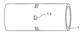
本発明の第1の方法では、まず、円筒芯体表面の一部に位置決め部材を設けて切断位置を規定する。位置決め部材としては、切断処理時に切断のための目印となれば特に限定されない。例えば、2つの無端ベルトを同時に作製する場合、無端ベルトが形成される領域でその中間に相当する箇所の円筒芯体表面の一部分に、図1に示すように、位置決め部材としての粘着テープ12を貼り付ける。その大きさは、5×5〜20×20mmまでの範囲であれば任意である。上記範囲より小さすぎると貼り付けたり剥がす作業がやりにくくなることがあり、大きすぎると皮膜の無効領域が多くなることがある。粘着テープ12の個数は、円筒芯体の外径や粘着テープの大きさにもよるが、円周方向に4〜12個程度が好ましい。個数が少ないと気体の通過量が不足することがあり、多すぎるとはがす手間が多くなることがある。
-Cutting position defining process-
In the first method of the present invention, first, a cutting member is defined by providing a positioning member on a part of the surface of the cylindrical core. The positioning member is not particularly limited as long as it becomes a mark for cutting during the cutting process. For example, when two endless belts are manufactured simultaneously, as shown in FIG. 1, an adhesive tape 12 as a positioning member is applied to a part of the surface of the cylindrical core at a position corresponding to the middle of the region where the endless belt is formed. paste. The size is arbitrary as long as it is in the range of 5 × 5 to 20 × 20 mm. If it is smaller than the above range, it may be difficult to apply or peel off, and if it is too large, the ineffective area of the film may increase. The number of adhesive tapes 12 is preferably about 4 to 12 in the circumferential direction, although it depends on the outer diameter of the cylindrical core and the size of the adhesive tape. If the number is small, the amount of gas passing may be insufficient, and if it is too large, the effort to remove may increase.
粘着テープ12の基材の材質は、塗液に侵されない物であれば何でもよく、ポリエステル、ナイロン、ポリイミド、ポリプロピレン等が好ましい。粘着テープを貼り付ける際、後で剥がしやすいよう、片方または両方に折り目を設けても良い。 The material of the base material of the adhesive tape 12 may be anything as long as it is not affected by the coating liquid, and polyester, nylon, polyimide, polypropylene and the like are preferable. When affixing the adhesive tape, a crease may be provided on one or both so that it can be easily peeled off later.
−PI前駆体塗膜形成工程−
次に、PI前駆体溶液を用意する。PI前駆体としては、種々の公知のものを用いることができる。また、PI前駆体は、2種以上を混合して用いてもよいし、複数の酸又はアミンのモノマーを混合して共重合されていてもよい。
-PI precursor coating film formation process-
Next, a PI precursor solution is prepared. As the PI precursor, various known ones can be used. Further, two or more kinds of PI precursors may be mixed and used, or a plurality of acid or amine monomers may be mixed and copolymerized.
PI前駆体の溶剤としては、N−メチルピロリドン、N,N−ジメチルアセトアミド、アセトアミド等の非プロトン系極性溶剤が挙げられる。PI前駆体溶液の混合比、濃度、粘度等は、塗布方法に応じて適宜選択される。 Examples of the solvent for the PI precursor include aprotic polar solvents such as N-methylpyrrolidone, N, N-dimethylacetamide, and acetamide. The mixing ratio, concentration, viscosity, etc. of the PI precursor solution are appropriately selected according to the coating method.
PI前駆体塗膜形成工程おいて、PI前駆体溶液の塗布方法としては、円筒芯体をPI前駆体溶液に浸漬して引き上げる浸漬塗布法、円筒芯体を回転させながら表面にPI前駆体溶液を吐出する流し塗り法、その際にブレードで塗膜を平滑化するブレード塗布法など、公知の方法が採用できる。上記流し塗り法やブレード塗布法では、塗布部を水平移動させるので、塗膜はらせん状に形成されるが、PI前駆体溶液は乾燥が遅いために、継ぎ目は自然に平滑になる。
なお、「円筒芯体上に塗布する」とは、円柱も含まれる円筒芯体の側面の表面、及び該表面に層を有する場合は、その層の表面に塗布することをいう。また、「円筒芯体を上昇」とは、塗布時の液面との相対関係であり、「円筒芯体を停止し、塗布液面を下降」させる場合を含む。
In the PI precursor coating film forming step, the PI precursor solution is applied by a dip coating method in which the cylindrical core body is dipped in the PI precursor solution and pulled up, or the PI precursor solution is applied to the surface while rotating the cylindrical core body. A known method such as a flow coating method for discharging the film and a blade coating method for smoothing the coating film with a blade can be employed. In the above-described flow coating method or blade coating method, the coating portion is moved horizontally, so that the coating film is formed in a spiral shape, but the PI precursor solution is slow to dry, so the seam is naturally smooth.
In addition, "applying on a cylindrical core body" means apply | coating to the surface of the surface of the side surface of a cylindrical core body also including a column, and when there is a layer in this surface. Further, “rising the cylindrical core” refers to a relative relationship with the liquid level during application, and includes the case of “stopping the cylindrical core and lowering the coating liquid level”.
PI前駆体塗膜形成工程おいて、PI前駆体溶液の塗布を浸漬塗布法で行う場合、PI前駆体溶液は粘度が非常に高いので、膜厚が所望値より厚くなりすぎることがある。その際は、特開2002−91027号公報に記載のような環状体により膜厚を制御する方法が適用できる。 In the PI precursor coating film forming step, when the PI precursor solution is applied by a dip coating method, the viscosity of the PI precursor solution is very high, and thus the film thickness may be too thick. In that case, a method of controlling the film thickness with an annular body as described in JP-A-2002-91027 can be applied.
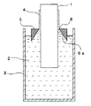
環状体により膜厚を制御する方法を、図4〜5を参照して説明する。図4は、環状体により膜厚を制御する浸漬塗布法に用いる装置の一例を示す概略構成図である。ただし、図は塗布するための主要部のみを示し、他の装置は省略している。
図4に示すように、この浸漬塗布法は、塗布槽3に満たされたPI前駆体溶液2に、円筒芯体1の外径よりも大きな孔6を設けた環状体5を浮かべ、該孔6を通して円筒芯体1をPI前駆体溶液2に浸漬し、次いで引き上げて塗布する塗布法である。
A method for controlling the film thickness by the annular body will be described with reference to FIGS. FIG. 4 is a schematic configuration diagram showing an example of an apparatus used for a dip coating method in which the film thickness is controlled by an annular body. However, the figure shows only the main part for coating, and other devices are omitted.
As shown in FIG. 4, this dip coating method floats an
環状体5の材質は、PI前駆体溶液2によって侵されない金属やプラスチック等から選ばれる。また、浮上しやすいように中空構造であってもよいし、沈没防止のために、環状体5の外周面または塗布槽3に、環状体5を支える足や腕を設けても良い。
The material of the
環状体5は、PI前駆体溶液2の上でわずかの力で動くことができよう、溶液上に浮遊させたり、環状体5をロールやベアリングで支える方法、環状体5をエア圧で支える方法、などの方法で水平方向に自由移動可能に設置する。
また、環状体5が塗布槽3の中央部に位置するように、環状体5を一時的に固定する固定手段を設けてもよい。固定手段を用いた場合、円筒芯体1を浸漬した後、引き上げる際には、環状体5が自由に動き得るように、該固定手段は取り外し可能なように配置されることが好ましい。
The
Moreover, you may provide the fixing means which fixes the
円筒芯体1の外径と、孔6の径との間隙により、塗膜4の膜厚が規制されるので、孔6の内径は、所望の膜厚により調整する。また、上記間隙により塗膜4の膜厚が決まるので、環状体の孔の真円度は重要である。真円度が低いと膜厚精度が低下するので、真円度は20μm以下であることが好ましく、10μm以下であることはさらに好ましい。もちろん、真円度が0μmであることが最適なのであるが、加工上は困難である。
Since the film thickness of the
環状体5に設けられる孔6の内壁面6aは、PI前駆体溶液に浸る下部が広く、上部が狭い形状であれば、図4に示すように、斜めの直線状である傾斜面であるものや、図5に示すように組み合わせた傾斜面であってもよい。また、階段状や曲線状でもよい。
As shown in FIG. 4, the inner wall surface 6a of the
塗布を行う際、円筒芯体1をPI前駆体溶液2に浸漬し、次いで、孔6の中を通して円筒芯体1を引き上げる。引き上げ速度は、0.1〜1.5m/min程度が好ましい。この塗布方法に好ましいPI前駆体溶液の固形分濃度は10〜40質量%、粘度は1〜100Pa・sである。
When coating, the
円筒芯体1を、孔6を通して引き上げると、環状体5は水平方向に自由移動可能であるため、円筒芯体1と環状体5との摩擦抵抗が周方向で一定になるように、環状体5は動く。即ち、円筒芯体1を引き上げる際、ある位置で、環状体5と円筒芯体1との間隙が狭まろうとした場合、狭まろうとした部分では摩擦抵抗が大きくなる一方、その反対側では摩擦抵抗が小さくなり、一時的に摩擦抵抗が不均一な状態が生じるが、環状体5は自由に動きうるので、そのような摩擦抵抗が不均一な状態から均一な状態になるように、環状体5が自動的に動く。そのため、環状体5が円筒芯体1と接触するようなことはない。従って、円筒芯体1の表面には、均一な膜厚のPI前駆体塗膜4が形成される。
When the
更に、浸漬塗布法に用いる塗布装置は、円筒芯体を保持する円筒芯体保持手段、並びに、所望により、該保持手段を上下方向に移動する第1の移動手段及び/又は塗布槽を上下方向に移動する第2の移動手段を有してもよい。 Further, the coating apparatus used for the dip coating method includes a cylindrical core body holding means for holding the cylindrical core body, and, if desired, a first moving means and / or a coating tank for moving the holding means in the vertical direction. You may have the 2nd moving means to move to.
このように、高粘度のPI前駆体溶液を用いて、環状体により膜厚を制御する浸漬塗布法を適用することで、重力による円筒芯体上端部での塗膜の垂れも少なくなり、周方向でも軸方向でも膜厚を均一にすることができる。 In this way, by applying the dip coating method in which the film thickness is controlled by the annular body using the high-viscosity PI precursor solution, dripping of the coating film at the upper end of the cylindrical core due to gravity is reduced, The film thickness can be made uniform both in the direction and in the axial direction.
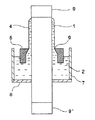
なお、PI前駆体塗膜形成工程おいて、図5に示す環状塗布法も適用できる。図5は、環状塗布法に用いる装置の一例を示す概略構成図である。
図5において、図4との違いは、環状塗布槽7の底部に、円筒芯体の外径より若干小さい穴を有する環状シール材8が設けられることである。円筒芯体1を環状シール材8の中心に挿通させ、環状塗布槽7にPI前駆体溶液2を収容する。これにより、PI前駆体溶液2は漏れることがない。円筒芯体1は、環状塗布槽7の下部から上部に順次つき上げられ、環状体5を挿通させることにより、表面に塗膜4が形成される。円筒芯体の上下には、円筒芯体に嵌合可能な中間体9、9’が取り付けられることもある。環状体の機能は、前述と同様である。
このような環状塗布法では、環状塗布槽7は図4の浸漬塗布槽3よりも小さくできるので、溶液の必要量が少なくて済む利点がある。
In the PI precursor coating film forming step, the annular coating method shown in FIG. 5 can also be applied. FIG. 5 is a schematic configuration diagram showing an example of an apparatus used for the annular coating method.
In FIG. 5, the difference from FIG. 4 is that an
In such an annular coating method, the annular coating tank 7 can be made smaller than the dip coating tank 3 of FIG.
以上のようなポリイミド前駆体塗膜形成工程の後に、前記位置決め部材を除去する。位置決め部材を除去した箇所には、穴が形成されるため、被膜が形成されている領域と明確に区別することができる。そのため、その除去した箇所に基づいて後述の切断処理を施せば、精度よく複数の無端ベルトを作製することができる。
なお、後述のポリイミド樹脂皮膜形成工程における乾燥前もしくは後に上記位置決め部材を除去してもよい。この場合も剥がした後には、皮膜に粘着テープの大きさに応じた穴が生じる。
After the polyimide precursor coating film forming step as described above, the positioning member is removed. Since a hole is formed at the position where the positioning member is removed, it can be clearly distinguished from the region where the film is formed. Therefore, a plurality of endless belts can be manufactured with high accuracy by performing a cutting process described later based on the removed portion.
The positioning member may be removed before or after drying in the polyimide resin film forming step described later. Also in this case, after peeling, a hole corresponding to the size of the adhesive tape is formed in the film.
−PI樹脂皮膜形成工程−
PI樹脂皮膜形成工程においては、以下のようにして、前記PI前駆体塗膜を加熱等の乾燥により反応させてPI樹脂皮膜を形成する。
まず、PI前駆体塗膜中に存在する溶剤の大部分を除去する目的で、塗膜を静置しても変形しない程度の加熱乾燥を行う。加熱条件は、90〜170℃の温度で30〜60分間が好ましい。その際、温度が高いほど、加熱時間は短くてよい。また、加熱することに加え、熱風を当てることも有効である。加熱は、時間内において、段階的に上昇させたり、一定速度で上昇させてもよい。
なお、PI前駆体塗膜から溶剤を除去しすぎると、塗膜はまだベルトとしての強度を保持していないので、割れを生じる虞がある。そこで、ある程度(具体的にはPI前駆体塗膜中に15〜45質量%)、溶剤を残留させておく方がよい。
-PI resin film formation process-
In the PI resin film forming step, the PI precursor film is reacted by drying such as heating to form a PI resin film as follows.
First, for the purpose of removing most of the solvent present in the PI precursor coating film, heat drying is performed to such an extent that it does not deform even when the coating film is left standing. The heating condition is preferably 90 to 170 ° C. and 30 to 60 minutes. At that time, the higher the temperature, the shorter the heating time. In addition to heating, it is also effective to apply hot air. Heating may be increased stepwise or at a constant rate over time.
If the solvent is removed too much from the PI precursor coating film, the coating film does not yet maintain the strength as a belt, and there is a risk of causing cracks. Therefore, it is better to leave the solvent to some extent (specifically, 15 to 45% by mass in the PI precursor coating film).
上記乾燥の後、好ましくは300〜450℃、より好ましくは350℃前後で、20〜60分間、PI前駆体塗膜を加熱反応させることで、PI樹脂皮膜を形成することができる。加熱反応の際、加熱の最終温度に達する前に、完全に残留溶剤を除去することが好ましく、具体的には、200〜250℃の温度で、10〜30分間加熱して残留溶剤を乾燥させ、続けて、温度を段階的、又は一定速度で徐々に上昇させて加熱することが好ましい。
第1の方法では皮膜に穴があるので、そこから気体が抜けるようになる。
After the drying, a PI resin film can be formed by heating and reacting the PI precursor coating film at a temperature of preferably 300 to 450 ° C., more preferably around 350 ° C. for 20 to 60 minutes. During the heating reaction, it is preferable to completely remove the residual solvent before reaching the final heating temperature. Specifically, the residual solvent is dried by heating at a temperature of 200 to 250 ° C. for 10 to 30 minutes. Subsequently, it is preferable to heat by gradually increasing the temperature stepwise or at a constant rate.
In the first method, since there is a hole in the film, gas can escape from there.
−PI樹脂皮膜加工工程−
PI樹脂皮膜加工工程では、加熱反応後、形成されたPI樹脂皮膜を円筒芯体から剥離し、切断処理を施して無端ベルトを得る工程である。
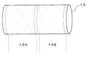
図6に示すように、抜き取られた無端ベルト10の両端部は、膜厚の均一性が劣っていたり、欠陥が多くあるため、不要部分として切断される。また、2つの無端ベルトを同時に作製する場合、目的とする無端ベルト10Aと10Bの間には、穴または内面に突起があるので、やはり不要部分として切断される。図6においては、点線が切断箇所である。
無端ベルトには、さらに必要に応じて、穴あけ(パンチング)加工、リブ付け加工、等が施されることがある。
-PI resin film processing-
In the PI resin film processing step, after the heat reaction, the formed PI resin film is peeled off from the cylindrical core body and subjected to a cutting process to obtain an endless belt.
As shown in FIG. 6, both end portions of the extracted
The endless belt may be further subjected to drilling (punching) processing, rib attaching processing, and the like as necessary.
(第2の方法)
本発明の第2の方法は、切断位置規定工程がポリイミド前駆体塗膜形成工程の前にあり、切断位置が円筒芯体の一部に孔を設けることで規定され、孔の存在によりポリイミド皮膜に形成された孔に基づいて前記切断処理を施すものである。その他の工程は第1の方法で説明したとおりである。
(Second method)
In the second method of the present invention, the cutting position defining step is before the polyimide precursor coating film forming step, the cutting position is defined by providing a hole in a part of the cylindrical core, and the polyimide film is formed by the presence of the hole. The cutting process is performed on the basis of the holes formed. Other steps are as described in the first method.
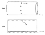
当該孔は気体を逃がすための意義も有し、例えば、2つの無端ベルトを作製する場合、無端ベルトが形成される領域でその中間に相当する箇所の円筒芯体に貫通孔を設ける。これについて、図2により説明する。 The hole also has a significance for letting gas escape. For example, when two endless belts are manufactured, a through hole is provided in a cylindrical core at a position corresponding to the middle of the region where the endless belt is formed. This will be described with reference to FIG.
図2は2本の無端ベルトを製造する場合の芯体の構造を説明する図面であり、(a)は斜視図、(b)は断面図である。図2中、円筒芯体1に貫通孔11を設けるが、等しい幅の無端ベルトを作製する場合、その位置は無端ベルトの中間に相当する箇所である。貫通孔の大きさは、大きすぎると液が入り込んで詰まる虞があり、小さすぎると気体の通過量が不足するので、0.2〜1.5mm程度が好ましい。貫通孔11の個数は、芯体の外径にもよるが、円周方向に4〜18個程度が好ましい。個数が少ないと気体の通過量が不足することになるが、多すぎるのは不要である。貫通孔の中にも離型剤を浸入させて塗布しておくのが好ましい。
貫通孔に塗布された部分の無端ベルトの内面には突起が生じることになるが、それは不要部分として切断するようにするため問題ない。なお、第2の方法では皮膜に穴があるので、そこから気体が抜けるようになる。
FIG. 2 is a drawing for explaining the structure of the core body in the case of manufacturing two endless belts, where (a) is a perspective view and (b) is a cross-sectional view. In FIG. 2, the through hole 11 is provided in the
Protrusions are formed on the inner surface of the endless belt applied to the through hole, but this is not a problem because it is cut as an unnecessary part. In the second method, since there is a hole in the film, gas can escape from there.
(第3の方法)
本発明の第3の方法は、切断位置規定工程がポリイミド前駆体塗膜形成工程とポリイミド樹脂皮膜形成工程との間にあり、切断位置がポリイミド前駆体塗膜の一部分を除去することで規定されてなり、除去された当該一部に基づいて切断処理を施すものである。その他の工程は第1の方法で説明したとおりである。
(Third method)
In the third method of the present invention, the cutting position defining step is between the polyimide precursor coating film forming step and the polyimide resin film forming step, and the cutting position is defined by removing a part of the polyimide precursor coating film. Thus, a cutting process is performed based on the removed part. Other steps are as described in the first method.
PI前駆体塗膜形成後、PI前駆体塗膜を加熱乾燥させる前に、例えば、2つの無端ベルトを作製する場合、無端ベルトが形成される領域でその無端ベルトの中間に相当する箇所のPI前駆体塗膜4の一部分を、図3に示すように除去して穴13をあける。その大きさは、直径2〜20mm程度であることが好ましい。小さすぎると気体を逃がす効果が不足し、大きすぎると皮膜の無効領域が多くなる。穴13の個数は、芯体の外径や穴の大きさにもよるが、円周方向に4〜12個程度が好ましい。個数が少ないと気体の通過量が不足し、多すぎるのは不要である。塗膜の一部分を除去する方法としては、紙や布等のウェスや、綿棒等で拭き取ったり、スポイトで吸い取る方法がある。なお、第3の方法では、芯体の貫通孔から気体が抜ける。
For example, when two endless belts are produced after the PI precursor coating is formed and before the PI precursor coating is heated and dried, the PI corresponding to the middle of the endless belt in the region where the endless belt is formed. A part of the
以上のようにして作製された無端ベルトを転写ベルトや、接触帯電ベルトとして使用する場合には、樹脂材料の中に必要に応じて導電性物質を分散させる。導電性物質としては、例えば、カーボンブラック、カーボンブラックを造粒したカーボンビーズ、カーボンファイバー、カーボンナノチューブ、グラファイト等の炭素系物質;銅、銀、アルミニウム等の金属又は合金;酸化錫、酸化インジウム、酸化アンチモン、SnO2−In2O3複合酸化物等の導電性金属酸化物;等が挙げられる。 When the endless belt produced as described above is used as a transfer belt or a contact charging belt, a conductive substance is dispersed in the resin material as necessary. Examples of the conductive material include carbon black, carbon-based materials such as carbon beads granulated from carbon black, carbon fiber, carbon nanotube, and graphite; metals or alloys such as copper, silver, and aluminum; tin oxide, indium oxide, And conductive metal oxides such as antimony oxide and SnO 2 —In 2 O 3 composite oxide.
無端ベルトを定着体として使用する場合には、表面に付着するトナーの剥離性の向上のため、ベルト表面に非粘着性の樹脂被膜を形成することが有効である。その非粘着性の樹脂被膜の材料としては、ポリテトラフルオロエチレン(PTFE)、テトラフルオロエチレン−パーフルオロアルキルビニルエーテル共重合体(PFA)、テトラフルオロエチレン−ヘキサフルオロプロピレン共重合体(FEP)等のフッ素系樹脂が好ましい。また、非粘着性の樹脂被膜には、耐久性や静電オフセットの向上のためにカーボン粉末が分散されていてもよい。 When an endless belt is used as a fixing member, it is effective to form a non-adhesive resin film on the belt surface in order to improve the releasability of the toner adhering to the surface. Examples of the non-adhesive resin coating material include polytetrafluoroethylene (PTFE), tetrafluoroethylene-perfluoroalkyl vinyl ether copolymer (PFA), and tetrafluoroethylene-hexafluoropropylene copolymer (FEP). A fluororesin is preferred. In addition, carbon powder may be dispersed in the non-adhesive resin film in order to improve durability and electrostatic offset.
上記フッ素系樹脂被膜を形成するには、その水分散液を無端ベルトの表面に塗布して焼き付け処理する方法が好ましい。このように、ベルト表面にフッ素系樹脂被膜を形成するには、無端ベルトを円筒芯体の表面に形成して加熱してから、これらを塗布してもよいが、PI前駆体溶液を塗布して溶剤を乾燥させた後、フッ素系樹脂分散液を塗布し、その後に加熱してイミド転化完結反応とフッ素系樹脂皮膜の焼成処理を同時に行ってもよい。この場合、プライマー層がなくてもフッ素系樹脂皮膜の密着性が強固になることもある。 In order to form the fluororesin coating, a method in which the aqueous dispersion is applied to the surface of the endless belt and baked is preferable. Thus, in order to form a fluorine resin film on the belt surface, an endless belt may be formed on the surface of the cylindrical core body and heated, and then these may be applied, but a PI precursor solution is applied. Then, after drying the solvent, a fluororesin dispersion may be applied, followed by heating to simultaneously complete the imide conversion reaction and the firing treatment of the fluororesin film. In this case, even if there is no primer layer, the adhesiveness of the fluororesin film may be strengthened.
無端ベルトを定着体として使用する場合、その厚さとしては25〜500μmの範囲であることが好ましい。必要に応じて設けられるプライマー層の厚さは0.5〜10μmの範囲が好ましい。また、フッ素系樹脂被膜の厚さは4〜40μmの範囲が好ましい。 When an endless belt is used as a fixing member, the thickness is preferably in the range of 25 to 500 μm. The thickness of the primer layer provided as necessary is preferably in the range of 0.5 to 10 μm. The thickness of the fluororesin coating is preferably in the range of 4 to 40 μm.
なお、本発明において、円筒芯体に形成された塗膜に顔料が含有されている場合、それらの厚さは、以下に説明するようにして測定することが好ましい。 In the present invention, when pigments are contained in the coating film formed on the cylindrical core, their thickness is preferably measured as described below.
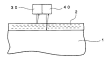
円筒芯体上に形成された塗膜もしくは皮膜に顔料が分散されている場合、それらに光透過性はないが、皮膜表面が平滑であるので反射率はきわめて高い。そこで、塗膜もしくは皮膜の膜厚測定は、静置状態を防ぎ、かつ効率的に測定するために、円筒芯体を水平回転させながら、図7に示すように、レーザ変位センサ30および渦電流式変位センサ40により行うことができる。
When pigments are dispersed in a coating film or a film formed on a cylindrical core, they are not light transmissive, but the reflectance is extremely high because the film surface is smooth. Therefore, the film thickness of the coating film or the film is measured as shown in FIG. 7 while rotating the cylindrical core horizontally in order to prevent the stationary state and to measure efficiently. This can be done by the
例えば、塗膜の厚さを測定する場合、まず、レーザ変位センサ30により塗膜4までの距離を測定する。その後、渦電流式変位センサ40により円筒芯体1表面までの距離を測定し、その差から膜厚を算出することができる。ここで、円筒芯体を水平回転させながら測定を行うことが好ましいが、その理由は、塗膜形成工程直後の塗膜はポリイミド前駆体を溶解する溶剤が約8割含まれており、かつこの溶剤が常温では蒸発しにくく、静置させると徐々に垂れが発生してしまうので、この垂れを防止することによる。一方、乾燥後の皮膜は、溶剤が約4割に減少するので静置しても垂れることはない。
For example, when measuring the thickness of the coating film, first, the distance to the
レーザ変位センサ30は塗膜4表面もしくは皮膜表面によりレーザ光が反射されるので、それらの外周面までの距離を測定することができる。一方、渦電流センサは塗膜4もしくは皮膜の存在にかかわらず、金属体までの距離を測定することができる。そのため、渦電流センサの導入により、円筒芯体1を水平回転させる際の振れや円筒芯体1自体の変形があっても、両者の差をとれば対処することができ、膜厚測定が可能となる。
Since the laser beam is reflected by the surface of the
ここで用いるレーザ変位センサ30は、例えば、レーザ波長が670nmで、レーザスポット径が楕円(短径30μm、長径850μm)のものを使用することで、塗膜もしくは皮膜の曲面に対する測定が可能となり、光沢面の測定が可能なものを使用する。一方、渦電流式変位センサ40は円筒芯体の材質がアルミやステンレスに対応すべくオールメタル仕様のものを使用する。
As the
以上により、レーザ変位センサと渦電流式変位センサとを併用することで、円筒芯体表面の塗膜もしくは皮膜の膜厚測定が可能となり、さらに円筒芯体を水平回転させる際に振れが発生した場合や、円筒芯体自体に変形があった場合でも、これらの影響を受けることなく膜厚が測定可能となる。 As described above, by using the laser displacement sensor and the eddy current displacement sensor in combination, it becomes possible to measure the film thickness of the coating film or film on the surface of the cylindrical core body, and further, vibration occurs when the cylindrical core body is rotated horizontally. Even when the cylindrical core itself is deformed, the film thickness can be measured without being affected by these effects.
[2]円筒芯体:
本発明の円筒芯体は、無端ベルトの製造方法に使用する円筒芯体であって、粗面化された外周面の一部にポリイミド皮膜の切断位置を規定するための位置決め処理が施されてなる。
一回の塗布作業にて複数の無端ベルト製造する際、最終的には、切断により複数の無端ベルトを製造することになるが、当該位置決め処理により切断位置が規定されていれば、精度よく所望の数の無端ベルトを得ることができる。また、後述する位置決め部材を具備することで、無端ベルトの製造段階において膨れ等の不良をより効果的に抑制することができる。
[2] Cylindrical core:
The cylindrical core body of the present invention is a cylindrical core body used in a method for manufacturing an endless belt, and a positioning process for defining a cutting position of a polyimide film is performed on a part of a roughened outer peripheral surface. Become.
When manufacturing a plurality of endless belts in a single coating operation, a plurality of endless belts will eventually be manufactured by cutting. If the cutting position is specified by the positioning process, it is desired with high accuracy. The number of endless belts can be obtained. Further, by providing a positioning member to be described later, it is possible to more effectively suppress defects such as swelling at the stage of manufacturing the endless belt.
位置決め処理は、切断位置に相当する箇所の一部に孔もしくは位置決め部材を設ける処理であることが好ましい。
切断位置に相当する箇所の一部に孔を設ける態様としては、具体的には、既述の第2の方法の例を挙げることができる。また、位置決め部材を設ける態様としては、既述の第1の方法の例を挙げることができる。
The positioning process is preferably a process in which a hole or a positioning member is provided in a part corresponding to the cutting position.
As an aspect which provides a hole in a part corresponding to a cutting position, the example of the above-mentioned 2nd method can be mentioned specifically ,. Moreover, as an aspect which provides a positioning member, the example of the above-mentioned 1st method can be given.
また、円筒芯体は、アルミニウムやステンレス等の金属製であることが好ましい。本発明において、円筒芯体の長さ(軸方向の長さ)は、2本以上の無端ベルトを作製するため、目的とする本数の無端ベルトの合計の幅以上の長さが必要である。さらに、両端部に生じる無効領域や、無端ベルトを切断して複数の無端ベルトを得るための切断位置に余裕幅を確保するため、円筒芯体の長さは、目的とする無端ベルトの本数分の長さより、10〜40%程度長いことが好ましい。円筒芯体の肉厚は、機械的及び熱的強度に耐え得ることが必要な程度で、円筒芯体の材質、外径によって異なるが、1〜30mm程度が好ましい。 The cylindrical core is preferably made of a metal such as aluminum or stainless steel. In the present invention, the length of the cylindrical core body (the length in the axial direction) needs to be equal to or greater than the total width of the target number of endless belts in order to produce two or more endless belts. Furthermore, the length of the cylindrical core is equal to the number of target endless belts in order to secure a margin at the ineffective area generated at both ends and the cutting position for cutting the endless belt to obtain a plurality of endless belts. It is preferable that the length is about 10 to 40% longer than the length. The thickness of the cylindrical core is required to withstand mechanical and thermal strength, and varies depending on the material and outer diameter of the cylindrical core, but is preferably about 1 to 30 mm.
また、既述のPI樹脂皮膜形成工程において、形成されるPI樹脂皮膜が円筒芯体表面に強く接着するおそれがあるため、円筒芯体の表面には、離型性が付与されていることが好ましい。それには、円筒芯体表面をクロムやニッケルでメッキしたり、フッ素樹脂やシリコーン樹脂で被覆したり、表面に離型剤を塗布する方法がある。 In addition, in the above-described PI resin film forming step, the formed PI resin film may strongly adhere to the surface of the cylindrical core body, and therefore the surface of the cylindrical core body may be provided with releasability. preferable. For example, the surface of the cylindrical core is plated with chromium or nickel, coated with a fluorine resin or silicone resin, or a mold release agent is applied to the surface.
前述したように、無端ベルトの製造段階において、PI樹脂皮膜の膨れを防止するために、円筒芯体の表面は、Ra0.2〜2μm程度に粗面化する。これにより、PI樹脂から生じる残留溶剤又は水の蒸気は、円筒芯体とPI樹脂皮膜との間にできるわずかな隙間を通って外部に出ることができ、膨れを防止する。円筒芯体表面の粗面化には、ブラスト、切削、サンドペーパーがけ等の方法がある。 As described above, the surface of the cylindrical core body is roughened to about Ra 0.2 to 2 [mu] m in order to prevent the swelling of the PI resin film at the stage of manufacturing the endless belt. Thereby, the residual solvent or water vapor generated from the PI resin can be discharged to the outside through a slight gap formed between the cylindrical core body and the PI resin film, thereby preventing swelling. For roughening the surface of the cylindrical core body, there are methods such as blasting, cutting, sandpapering and the like.
以下、本発明を実施例により具体的に説明する。ただし、各実施例は、本発明を制限するものではない。 Hereinafter, the present invention will be specifically described by way of examples. However, each example does not limit the present invention.
(実施例1)
−PI前駆体塗膜形成工程−
BPDA(3’,4,4’−ビフェニルテトラカルボン酸二無水物)とPDA(p−フェニレンジアミン)とをN,N−ジメチルアセトアミド中で合成した20質量%濃度のPI前駆体溶液Aを調製した。粘度は35Pa・sであった。
(Example 1)
-PI precursor coating film formation process-
Preparation of 20 mass% PI precursor solution A prepared by synthesizing BPDA (3 ′, 4,4′-biphenyltetracarboxylic dianhydride) and PDA (p-phenylenediamine) in N, N-dimethylacetamide did. The viscosity was 35 Pa · s.
外径68mm、長さ800mmのアルミニウム製円筒を用意した。これに球形アルミナ粒子によるブラスト処理を行い、表面をRa1.0μmに粗面化した。更に、端部から400mmの中央位置に、直径0.8mmの貫通孔を円周方向に等間隔に6個あけた(切断位置規定工程)。
次いで、表面と貫通孔内部に、シリコーン系離型剤(商品名:KS700、信越化学(株)製)を塗布して、300℃で1時間、焼き付け処理を施し、円筒芯体とした。
An aluminum cylinder having an outer diameter of 68 mm and a length of 800 mm was prepared. This was blasted with spherical alumina particles to roughen the surface to Ra 1.0 μm. Furthermore, six through-holes with a diameter of 0.8 mm were formed at equal intervals in the circumferential direction at a central position of 400 mm from the end (cutting position defining step).
Next, a silicone release agent (trade name: KS700, manufactured by Shin-Etsu Chemical Co., Ltd.) was applied to the surface and the inside of the through-hole, and baked at 300 ° C. for 1 hour to obtain a cylindrical core.
図5に示す環状塗布法により、PI前駆体溶液を円筒芯体上に塗布した。環状体5としては、外径110mm、最小部の内径69.2mm、高さ30mmのアルミニウム製のものを作製した。内壁は直線傾斜状であり、鉛直線との傾斜角は7°とし、内径の真円度は13μmであった。
円筒芯体1の上下に中間体9、9’を取り付けた。中間体9の底面に、内径66mmの穴を有するポリエチレン製環状シール材8が取り付けられた、内径150mm、高さ50mmの環状塗布槽3’に通した。環状塗布槽3’にPI前駆体溶液2を入れ、環状体5を配置して、円筒芯体1を0.5m/分で上昇させ、塗布を行った。これにより、円筒芯体1の表面には濡れ膜厚が約600μmのPI前駆体塗膜4が形成された。
The PI precursor solution was applied onto the cylindrical core body by the annular coating method shown in FIG. As the
Intermediate bodies 9 and 9 ′ were attached to the top and bottom of the
−PI樹脂皮膜形成工程−
次に、円筒芯体を水平にして、20rpmで回転させながら、室温で5分間の乾燥後、80℃で20分間、100℃で1時間、加熱乾燥させた。これにより、厚さ約150μmのPI前駆体塗膜を得た。次に、円筒芯体を一旦、室温まで冷却した。この際、PI前駆体塗膜はその軸方向に約1%収縮した。
-PI resin film formation process-
Next, the cylindrical core was horizontal and rotated at 20 rpm, followed by drying at room temperature for 5 minutes, followed by heat drying at 80 ° C. for 20 minutes and at 100 ° C. for 1 hour. Thereby, a PI precursor coating film having a thickness of about 150 μm was obtained. Next, the cylindrical core was once cooled to room temperature. At this time, the PI precursor coating film contracted by about 1% in the axial direction.
その後、PI前駆体塗膜の一端部に、幅20mmのポリエステルテープを巻き付けて被覆処理をした。次に、PFA(テトラフルオロエチレン−パーフルオロアルキルビニルエーテル共重合体)のディスパージョン水性塗料(商品名:710CL、三井デュポンフロロケミカル社製)を内径90mm、高さ900mmの塗布槽に入れ、その中に円筒芯体を、被覆部を下側にして液面に対し垂直にし、上部のポリイミド前駆体塗膜を5mmだけ残して浸漬した。次いで、0.2m/minの速度で引き上げ、PFA塗膜を形成した。引き上げ終了後、ポリエステルテープを除去し、80℃で10分間、乾燥をした。更に、150℃で20分間、続いて200℃で20分間加熱し、その後、380℃で30分間加熱して、PI樹脂皮膜を形成すると共に、PFA塗膜を焼成した。 Thereafter, a polyester tape having a width of 20 mm was wound around one end of the PI precursor coating film to perform a coating treatment. Next, a PFA (tetrafluoroethylene-perfluoroalkyl vinyl ether copolymer) dispersion water-based paint (trade name: 710CL, manufactured by Mitsui Dupont Fluoro Chemical Co., Ltd.) was placed in a coating tank having an inner diameter of 90 mm and a height of 900 mm. The cylindrical core body was immersed with the covering portion on the bottom and perpendicular to the liquid surface, leaving the upper polyimide precursor coating film by 5 mm. Subsequently, it pulled up at a speed of 0.2 m / min to form a PFA coating film. After the pulling up, the polyester tape was removed and dried at 80 ° C. for 10 minutes. Furthermore, it was heated at 150 ° C. for 20 minutes, then at 200 ° C. for 20 minutes, and then heated at 380 ° C. for 30 minutes to form a PI resin film, and the PFA coating film was baked.
−PI樹脂皮膜加工工程−
室温に冷えた後、芯体から皮膜を取り外した。これは75μm厚のPI樹脂の無端ベルト上に、30μm厚のPFA層を有しており、皮膜に膨れは生じていなかった。また、PI樹脂の内面は、Ra0.8μmの粗面であり、中央部分には、芯体に設けた貫通孔に対応する箇所に小さな突起が見られた。この方法はPI樹脂皮膜に穴をあけるわけではないので、重ね塗りをする場合には好適である。
次いで図6に示すように、無端ベルト10の両端から約30mmずつ、及び中央側から約10mmずつ切断し、無端ベルト10A、10Bを得た。
この無端ベルトは、電子写真用定着ベルトとして好適に使用することができた。
-PI resin film processing-
After cooling to room temperature, the film was removed from the core. This had a 30 μm-thick PFA layer on an endless belt of 75 μm-thick PI resin, and the film did not swell. In addition, the inner surface of the PI resin was a rough surface of Ra 0.8 μm, and a small protrusion was seen at the center portion corresponding to the through hole provided in the core body. Since this method does not make a hole in the PI resin film, it is suitable for overcoating.
Next, as shown in FIG. 6, endless belts 10A and 10B were obtained by cutting about 30 mm from both ends of
This endless belt could be suitably used as an electrophotographic fixing belt.
(実施例2)
−PI前駆体塗膜形成工程−
実施例1と同じPI前駆体溶液Aに、カーボンブラック(商品名:スペシャルブラック4、デグザヒュルス社製)を固形分質量比で23%混合し、次いで対向衝突型分散機により分散した。更に、塗膜の塗工性を向上させるため、シリコーンレベリング剤(商品名:DC3PA、ダウコーニングトーレシリコーン社製)を、濃度が500ppmになるよう添加し、PI前駆体溶液Bとした。
(Example 2)
-PI precursor coating film formation process-
Carbon black (trade name:
別途、外径366mm、長さ900mmのアルミニウム製円筒を用意し、球形アルミナ粒子によるブラスト処理により、表面をRa1.0μmに粗面化した。その表面には、シリコーン系離型剤(実施例1と同じ)を塗布して、300℃で1時間、焼き付け処理を施し、円筒芯体とした。 Separately, an aluminum cylinder having an outer diameter of 366 mm and a length of 900 mm was prepared, and the surface was roughened to Ra 1.0 μm by blasting with spherical alumina particles. On the surface, a silicone release agent (same as in Example 1) was applied, and baked at 300 ° C. for 1 hour to obtain a cylindrical core.
PI前駆体溶液BBを用い、図5に示す環状塗布法により、PI前駆体塗膜を形成した。環状体5として、外径420mm、最小部の内径367.1mm、高さ50mmのアルミニウム製のものを作製した。内壁は直線傾斜状であり、鉛直線との傾斜角は7°とし、内径の真円度は15μmであった。
Using the PI precursor solution BB, a PI precursor coating film was formed by the annular coating method shown in FIG. As the
円筒芯体1を、底面に内径166mmの穴を有するポリエチレン製の環状シール材8を取り付け、環状塗布槽7(内径450mm、高さ100mm)に通した。環状塗布槽7にPI前駆体溶液2を入れ、環状体5を配置して、円筒芯体1を0.4m/分で上昇させ、塗布を行った。これにより、円筒芯体の表面には、濡れ膜厚が約500μmのPI前駆体塗膜4が形成された。
The
−PI樹脂皮膜形成工程−
PI前駆体塗膜が形成された円筒芯体を水平にし、回転自在状態に保持した。次いで、図3に示すように、PI前駆体塗膜4の中央部分を小さなスポンジでこすり取り、直径約5mmの穴13を6箇所あけた(切断位置規定工程)。室温で5分間の乾燥後、6rpmで回転させながら、80℃で20分間、130℃で30分間、加熱して乾燥させ、次に、円筒芯体を室温まで冷却した。これにより、厚さ約150μmのPI樹脂塗膜を得た。その後、円筒芯体を垂直にして、200℃で30分、340℃で30分加熱反応させ、PI樹脂皮膜を形成した。
-PI resin film formation process-
The cylindrical core body on which the PI precursor coating film was formed was leveled and held in a rotatable state. Next, as shown in FIG. 3, the central portion of the PI
−PI樹脂皮膜加工工程−
室温に冷えた後、円筒芯体からPI樹脂皮膜を抜き取った。このPI樹脂皮膜は、膜厚75μmで均一であった。
得られたPI樹脂皮膜10は、図6に示すように不要部分を両端から30mmずつ切断し、さらに中央側から約20mmずつ切断し、無端ベルト10A、10Bを得た。
この無端ベルトは、電子写真用転写ベルトとして好適に使用することができた。
-PI resin film processing-
After cooling to room temperature, the PI resin film was extracted from the cylindrical core. This PI resin film was uniform with a film thickness of 75 μm.
As shown in FIG. 6, the obtained
This endless belt could be suitably used as an electrophotographic transfer belt.
(実施例3)
−PI前駆体塗膜形成工程−
実施例2の円筒芯体の中央部分に、図2に示すように、5×10mmに切ったポリエステル粘着テープ12を、円周方向6箇所に貼り付けた(切断位置規定工程)。次いで、他は実施例2と同様にしてPI前駆体塗膜を形成した。
(Example 3)
-PI precursor coating film formation process-
As shown in FIG. 2, polyester adhesive tapes 12 cut to 5 × 10 mm were attached to the central portion of the cylindrical core body of Example 2 at six locations in the circumferential direction (cutting position defining step). Subsequently, a PI precursor coating film was formed in the same manner as in Example 2.
−PI樹脂皮膜形成工程−
PI前駆体塗膜の乾燥後、円筒芯体から前記ポリエステル粘着テープをピンセットでつまんで除去したところ、PI前駆体塗膜には約5×10mmの穴が形成された。その際、PI前駆体塗膜が裂けないよう注意した。他は実施例2と同様にしてPI樹脂皮膜を形成した。この方法によっても実施例2と同様の無端ベルトを得ることができた。
-PI resin film formation process-
After the PI precursor coating was dried, the polyester adhesive tape was removed from the cylindrical core by tweezers. As a result, a hole of about 5 × 10 mm was formed in the PI precursor coating. At that time, care was taken not to tear the PI precursor coating film. Otherwise, a PI resin film was formed in the same manner as in Example 2. Also by this method, the same endless belt as in Example 2 could be obtained.
(比較例1)
円筒芯体に貫通孔を設けずに2本の無端ベルトを作製した以外は実施例1と同様にして、円筒芯体上の無端ベルトの中央部分には、直径20〜30mmで、高さが数mmの膨れがいくつか生じており、実施例1〜3の無端ベルトと比べ、劣ったものであった。
(Comparative Example 1)
The central portion of the endless belt on the cylindrical core has a diameter of 20 to 30 mm and a height that is the same as in Example 1 except that two endless belts were prepared without providing through holes in the cylindrical core. Several blisters of several mm occurred, which was inferior to the endless belts of Examples 1 to 3.
なお、塗膜および皮膜の膜厚は、以下のようにして測定した。すなわち、円筒芯体を水平にし、6rpmで回転させながら、レーザ変位センサ(キーエンス製、商品名;LK−035)と渦電流式変位センサ(キーエンス製、商品名;EX−022)を備えた装置にて芯体からのそれぞれの距離を測定し、その差から膜厚を計測した。
また、レーザ変位センサのレーザ波長は670nmで、レーザスポット径が楕円(短径30μm、長径850μm)のものを使用した。
In addition, the film thickness of the coating film and the film was measured as follows. That is, an apparatus provided with a laser displacement sensor (manufactured by Keyence, product name; LK-035) and an eddy current displacement sensor (manufactured by Keyence, product name: EX-022) while the cylindrical core body is leveled and rotated at 6 rpm. Each distance from the core was measured at, and the film thickness was measured from the difference.
Further, the laser wavelength of the laser displacement sensor was 670 nm, and the laser spot diameter was an ellipse (
1・・・ 円筒芯体
2・・・ポリイミド前駆体溶液
3・・・塗布槽
4・・・ポリイミド前駆体塗膜
5・・・環状体
6・・・環状体の孔
7・・・環状塗布槽
8・・・環状シール材
9,9’ ・・・中間体
10・・・無端ベルト
11・・・貫通孔
12・・・粘着テープ
13・・・穴
30・・・レーザ変位センサ
40・・・渦電流式変位センサ
DESCRIPTION OF
Claims (6)
前記ポリイミド前駆体塗膜を乾燥させてポリイミド樹脂皮膜を形成するポリイミド樹脂皮膜形成工程と、
前記ポリイミド樹脂皮膜を前記円筒芯体から剥離し、切断処理を施して無端ベルトを得るポリイミド樹脂皮膜加工工程と、を有する無端ベルトの製造方法であって、
前記ポリイミド前駆体塗膜形成工程の前工程もしくは後工程として、前記切断処理の際の切断位置を規定しておく切断位置規定工程を有し、
前記切断処理による切断が前記切断位置に基づいて行われ、当該切断処理により複数の無端ベルトを作製することを特徴とする無端ベルトの製造方法。 A polyimide precursor coating film forming step of forming a polyimide precursor coating film by applying a polyimide precursor solution to the outer peripheral surface side of the cylindrical core body having a roughened surface;
A polyimide resin film forming step of drying the polyimide precursor coating film to form a polyimide resin film;
The polyimide resin film is peeled from the cylindrical core, and a polyimide resin film processing step for obtaining an endless belt by performing a cutting process, and a method for producing an endless belt,
As a pre-process or post-process of the polyimide precursor coating film forming step, it has a cutting position defining step for prescribing a cutting position at the time of the cutting treatment,
A method of manufacturing an endless belt, wherein cutting by the cutting process is performed based on the cutting position, and a plurality of endless belts are manufactured by the cutting process.
Priority Applications (1)
| Application Number | Priority Date | Filing Date | Title |
|---|---|---|---|
| JP2004040343A JP2005231079A (en) | 2004-02-17 | 2004-02-17 | Endless belt manufacturing method and cylindrical core body |
Applications Claiming Priority (1)
| Application Number | Priority Date | Filing Date | Title |
|---|---|---|---|
| JP2004040343A JP2005231079A (en) | 2004-02-17 | 2004-02-17 | Endless belt manufacturing method and cylindrical core body |
Publications (2)
| Publication Number | Publication Date |
|---|---|
| JP2005231079A true JP2005231079A (en) | 2005-09-02 |
| JP2005231079A5 JP2005231079A5 (en) | 2007-04-05 |
Family
ID=35014528
Family Applications (1)
| Application Number | Title | Priority Date | Filing Date |
|---|---|---|---|
| JP2004040343A Withdrawn JP2005231079A (en) | 2004-02-17 | 2004-02-17 | Endless belt manufacturing method and cylindrical core body |
Country Status (1)
| Country | Link |
|---|---|
| JP (1) | JP2005231079A (en) |
Cited By (1)
| Publication number | Priority date | Publication date | Assignee | Title |
|---|---|---|---|---|
| JP2007100208A (en) * | 2005-09-12 | 2007-04-19 | Fuji Xerox Co Ltd | Core, method for regenerating core, and method for producing endless resin belt |
-
2004
- 2004-02-17 JP JP2004040343A patent/JP2005231079A/en not_active Withdrawn
Cited By (1)
| Publication number | Priority date | Publication date | Assignee | Title |
|---|---|---|---|---|
| JP2007100208A (en) * | 2005-09-12 | 2007-04-19 | Fuji Xerox Co Ltd | Core, method for regenerating core, and method for producing endless resin belt |
Similar Documents
| Publication | Publication Date | Title |
|---|---|---|
| JP5076284B2 (en) | Endless belt manufacturing method | |
| JP2004029757A (en) | Endless belt and its manufacturing method, and image fixing device using same | |
| JP2003255640A (en) | Polyimide resin endless belt and method for manufacturing the same | |
| JP2004094042A (en) | Endless belt made of polyimide resin and its manufacture method | |
| JP2008122907A (en) | Belt covered with fluororesin tube, manufacturing method thereof, fixing device and image forming apparatus | |
| JP2005231079A (en) | Endless belt manufacturing method and cylindrical core body | |
| JP2009045577A (en) | Method for forming fluorocarbon resin coating film and object having coating film formed thereby | |
| JP4706432B2 (en) | Core mold for seamless tubular body, method for producing core mold for seamless tubular body, and method for producing seamless tubular body using core mold | |
| JP2008112097A (en) | Endless belt, manufacturing method of the same, fixing device, and image forming apparatus | |
| JP2008200954A (en) | Pfa coated polyimide tube, its manufacturing method and pressurizing belt made of the same | |
| JP4396096B2 (en) | Method for producing endless belt made of polyimide resin, and endless belt made of polyimide resin | |
| JP2004255708A (en) | Method for producing endless belt of polyimide resin and the endless belt | |
| JP2004046062A (en) | Endless belt and method of manufacturing the same | |
| JP2002160239A (en) | Method for forming film, jointless belt, and manufacturing method for jointless belt | |
| JP4045818B2 (en) | Polyimide resin endless belt and manufacturing method thereof | |
| JP4806903B2 (en) | Cylindrical core, coating device, and method for producing polyimide resin endless belt | |
| JP4419583B2 (en) | Endless belt and fixing belt manufacturing method | |
| JP2007296839A (en) | Cylindrical core body and method for manufacturing endless belt using cylindrical core body | |
| JP2008225182A (en) | Polyimide belt and method for manufacturing thereof | |
| JP2006240099A (en) | Endless belt made of thermosetting resin and its production method | |
| JP3109925B2 (en) | Composite tubular article and method for producing the same | |
| JP2006239898A (en) | Method and apparatus for manufacturing endless belt | |
| JP2007296838A (en) | Cylindrical core body and method for producing endless belt using the core body | |
| JP2005246632A (en) | Polyimide resin endless belt manufacturing method | |
| JP2004268367A (en) | Endless belt made of polyimide resin and its manufacturing method |
Legal Events
| Date | Code | Title | Description |
|---|---|---|---|
| A521 | Written amendment |
Free format text: JAPANESE INTERMEDIATE CODE: A523 Effective date: 20070219 |
|
| A621 | Written request for application examination |
Free format text: JAPANESE INTERMEDIATE CODE: A621 Effective date: 20070219 |
|
| A761 | Written withdrawal of application |
Free format text: JAPANESE INTERMEDIATE CODE: A761 Effective date: 20080619 |