JP2005230010A - Method and apparatus for removing foreign materials from tobacco to be processed - Google Patents
Method and apparatus for removing foreign materials from tobacco to be processed Download PDFInfo
- Publication number
- JP2005230010A JP2005230010A JP2005042083A JP2005042083A JP2005230010A JP 2005230010 A JP2005230010 A JP 2005230010A JP 2005042083 A JP2005042083 A JP 2005042083A JP 2005042083 A JP2005042083 A JP 2005042083A JP 2005230010 A JP2005230010 A JP 2005230010A
- Authority
- JP
- Japan
- Prior art keywords
- transport
- material flow
- conveying
- tobacco
- foreign matter
- Prior art date
- Legal status (The legal status is an assumption and is not a legal conclusion. Google has not performed a legal analysis and makes no representation as to the accuracy of the status listed.)
- Withdrawn
Links
Images


Classifications
-
- A—HUMAN NECESSITIES
- A24—TOBACCO; CIGARS; CIGARETTES; SIMULATED SMOKING DEVICES; SMOKERS' REQUISITES
- A24B—MANUFACTURE OR PREPARATION OF TOBACCO FOR SMOKING OR CHEWING; TOBACCO; SNUFF
- A24B1/00—Preparation of tobacco on the plantation
- A24B1/04—Sifting, sorting, cleaning or removing impurities from tobacco
-
- A—HUMAN NECESSITIES
- A24—TOBACCO; CIGARS; CIGARETTES; SIMULATED SMOKING DEVICES; SMOKERS' REQUISITES
- A24C—MACHINES FOR MAKING CIGARS OR CIGARETTES
- A24C5/00—Making cigarettes; Making tipping materials for, or attaching filters or mouthpieces to, cigars or cigarettes
- A24C5/39—Tobacco feeding devices
- A24C5/396—Tobacco feeding devices with separating means, e.g. winnowing, removing impurities
-
- B—PERFORMING OPERATIONS; TRANSPORTING
- B07—SEPARATING SOLIDS FROM SOLIDS; SORTING
- B07C—POSTAL SORTING; SORTING INDIVIDUAL ARTICLES, OR BULK MATERIAL FIT TO BE SORTED PIECE-MEAL, e.g. BY PICKING
- B07C5/00—Sorting according to a characteristic or feature of the articles or material being sorted, e.g. by control effected by devices which detect or measure such characteristic or feature; Sorting by manually actuated devices, e.g. switches
- B07C5/34—Sorting according to other particular properties
- B07C5/344—Sorting according to other particular properties according to electric or electromagnetic properties
Landscapes
- Life Sciences & Earth Sciences (AREA)
- Agronomy & Crop Science (AREA)
- Manufacturing Of Cigar And Cigarette Tobacco (AREA)
- Control Of Conveyors (AREA)
- Feeding Of Articles To Conveyors (AREA)
- Manufacture Of Tobacco Products (AREA)
- Combined Means For Separation Of Solids (AREA)
Abstract
Description
本発明は、たばこの搬送方向Tに向けて、実質的にたばこからなる材料流を供給するための供給装置と、材料流から異物を除去するための装置と、材料流を加速する少なくとも1つの搬送要素と、たばこから異物を分離するための装置を有する、他の異物を検出するための光学式検査要素とを備えている、加工すべきたばこから異物を取り除くための装置に関する。本発明は更に、実質的にたばこからなる材料流を、加工すべきたばこから異物を除去するための装置に供給し、然るべき装置によって材料流から異物を除去し、材料流を加速する搬送要素に材料流を案内し、光学式検査要素によって他の異物を検出し、そしてたばこから異物を分離する、加工すべきたばこから異物を取り除くための方法に関する。 The present invention provides a supply device for supplying a material flow consisting essentially of cigarettes in the tobacco transport direction T, a device for removing foreign matter from the material flow, and at least one for accelerating the material flow. The present invention relates to an apparatus for removing foreign matter from tobacco to be processed, comprising a transport element and an optical inspection element for detecting other foreign matter, having a device for separating foreign matter from tobacco. The present invention further provides a conveying element that feeds a material stream consisting essentially of tobacco to an apparatus for removing foreign matter from the tobacco to be processed, removes the foreign matter from the material stream by appropriate equipment, and accelerates the material flow. The present invention relates to a method for removing foreign matter from tobacco to be processed, guiding the material flow, detecting other foreign matter by means of an optical inspection element, and separating the foreign matter from the tobacco.
このような装置と方法はたばこ加工産業においてプライマリーとも呼ばれるたばこの準備において使用される。一般的に梱等として袋、箱等に詰められたたばこを、後の紙巻きたばこ製造のために準備するために、請求項1の前提部分の特徴を有する装置と、請求項15の前提部分に記載したステップを有する方法が知られている。材料流を準備するためには、通常不均一に分配された厚層のたばこから、理想的にはいわゆるたばこの均一な単一層を生じる必要がある。それによって、材料流内の異物の検出および材料流からの異物の分離が簡単化されるかまたは可能になる。このような装置は供給装置、材料流からの異物の除去装置およびいわゆるひも除去器のほかに、材料流を均一化する振動要素、例えば振動ベルトまたは振動シュートを備えている。搬送方向において振動要素の後には、材料流を加速するための2段の搬送要素が設けられている。この搬送要素の端部には光学式検査要素が配置されている。この検査要素は前もって検出された異物を分離するように形成され、そのために適当な装置を備えている。
Such devices and methods are used in the preparation of tobacco, also called primary in the tobacco processing industry. In order to prepare cigarettes generally packed in bags, boxes, etc. for later cigarette manufacture, the apparatus having the features of the premise of claim 1 and the premise of
しかし、このような装置と方法は、構成要素が多数であるため非常に大型であるという欠点を有する。他方では、この公知の装置の製造は特に構成要素が多いので非常に費用がかかり、方法の実施も非常に費用がかかる。 However, such devices and methods have the disadvantage of being very large due to the large number of components. On the other hand, the production of this known device is very expensive, especially because of its many components, and the implementation of the method is also very expensive.
そこで、本発明の課題は、少なくとも従来の装置と同じように、材料流を単一層に分配する、低コストでコンパクトな装置を提供することである。本発明の課題は更に、管理が容易で、必要な品質の単一層への材料流の分配を省スペースで可能にする低コストの方法を提供することである。 It is therefore an object of the present invention to provide a low-cost and compact device that distributes a material flow into a single layer, at least as in conventional devices. It is a further object of the present invention to provide a low-cost method that is easy to manage and allows space-saving distribution of material flow into a single layer of the required quality.
この課題は冒頭に述べた種類の装置において、異物を除去するための装置が、材料流を加速する搬送要素のすぐ上に配置されていることによって解決される。それによって、構成要素の数が減少する。なぜなら、例えば通常は異物を除去する装置の下方にある搬送要素や、この装置の後に配置された振動要素を省略することができるからである。それによって、きわめてコンパクトで低コストで製作可能な装置が形成される。本発明に従って、異物を除去する装置を、材料流を加速する搬送要素の上方に配置することにより、材料流の直接的な供給が補償されるので、材料流の移行距離が短くなる。従って、たばこはきわめてやさしく搬送される。装置によって更に、材料流の良好な予備分配が達成される。 This problem is solved in the device of the type mentioned at the outset by the fact that the device for removing foreign substances is arranged directly above the conveying element that accelerates the material flow. Thereby, the number of components is reduced. This is because, for example, it is possible to omit the conveying element below the apparatus for removing foreign substances or the vibration element arranged after this apparatus. This creates a device that is extremely compact and can be manufactured at low cost. In accordance with the present invention, the device for removing foreign matter is arranged above the conveying element that accelerates the material flow, so that the direct supply of the material flow is compensated, so that the material flow transition distance is shortened. Therefore, cigarettes are transported very gently. The apparatus further achieves a good pre-distribution of the material flow.
異物を除去するための装置が並べて配置されかつ回転駆動装置によって回転可能である多数の除去ローラによって形成され、除去ローラの回転速度または搬送速度が材料流を加速する搬送要素の搬送速度と異なっている、すなわち好ましくは遅い。この速度差によって、きわめて効果的な均一化が達成されるので、その前は厚層で不均一であった材料流を、均一なたばこ単一層に変えることができる。 A device for removing foreign substances is formed side by side and formed by a number of removal rollers that can be rotated by a rotary drive device, and the rotational speed or conveying speed of the removing roller is different from the conveying speed of the conveying element that accelerates the material flow That is, preferably slow. This speed difference achieves a very effective homogenization, so that a material flow that was previously non-uniform in thick layers can be converted into a uniform layer of cigarettes.
本発明の有利な実施形では、材料流を加速する少なくとも2個の搬送要素が設けられ、この搬送要素が前後に並べて段滝状に配置され、後側の搬送要素の範囲内に、特に金属からなる異物のための検出要素が配置されている。それによって、装置全体の必要スペースを大きくしないで、任意に使用可能な付加的な構成要素が統合される。 In an advantageous embodiment of the invention, at least two transport elements for accelerating the material flow are provided, which transport elements are arranged side by side in a stepped waterfall, within the range of the rear transport elements, in particular metal. A detection element for foreign matter consisting of is arranged. Thereby, optional additional components can be integrated without increasing the overall space requirements of the device.
更に、篩が光学式検査要素に直接付設される、すなわち光学式検査要素のすぐ後に配置されるように、篩と光学式検査要素がユニットを形成しているときわめて有利である。これは同様に、装置をコンパクトに配置する。 Furthermore, it is very advantageous if the sieve and the optical inspection element form a unit so that the sieve is directly attached to the optical inspection element, i.e. arranged immediately after the optical inspection element. This likewise places the device in a compact manner.
課題は冒頭に述べた方法において、材料流がそれから異物を除去するための装置によって、材料流を加速する搬送要素に直接案内され、搬送要素への材料流の供給が上側から行われることによって解決される。これは異物の低コストの除去を可能にする。というのは、異物および/または混在物の検出および除去のための前提である、狭い必要スペースでの材料流の確実な均一化が達成されるからである。 The problem is solved in the method described at the outset, in which the material flow is guided directly to the conveying element which accelerates the material flow by means of a device for removing foreign substances and the material flow is supplied to the conveying element from above. Is done. This allows low cost removal of foreign objects. This is because reliable homogenization of the material flow in a narrow required space, which is a precondition for detecting and removing foreign substances and / or contaminants, is achieved.
好ましくは、搬送要素が除去ローラよりも速い速度、好ましくは2〜3倍の速度で駆動される。それによって、長さと幅方向に最適におよび均一に分配された単一層が形成される。 Preferably, the transport element is driven at a faster speed than the removal roller, preferably 2-3 times. Thereby, a single layer is formed that is optimally and uniformly distributed in the length and width direction.
有利で好ましい他の特徴と発展形態は、従属請求項と次の記載から明らかである。きわめて好ましい実施の形態と方法を、添付の図に基づいて詳しく説明する。 Other advantageous and preferred features and developments are evident from the dependent claims and the following description. Highly preferred embodiments and methods will now be described in detail with reference to the accompanying figures.
図示した装置は、通常連続的に搬送される材料流から、例えば包装材の糸、金属部品等の異物を取り除く働きをする。 The apparatus shown in the figure serves to remove foreign matter such as, for example, packaging material threads, metal parts, etc., from a material stream that is normally conveyed continuously.
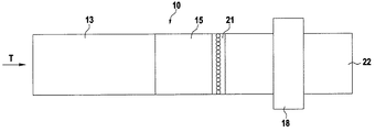
図1の装置10は供給装置11を備えている。この供給装置はシュート、コンベヤベルト、スライダ等として形成可能である。供給装置11上には加工すべき材料流12が設けられている。この材料流は供給装置11上に載せられるかまたは注がれるかまたは他の方法で配置され、搬送方向Tに連続的にまたは間欠的に搬送される。供給装置11の範囲内の材料流は一般的に、搬送方向Tとそれに対して横方向に不規則的におよび厚層状に分布している。搬送方向Tにおいて供給装置11の次に、材料流12から異物を除去するための装置13が配置されている。この場合、装置13は垂直方向において供給装置11よりも少しだけ下方に配置されている。それによって、材料流12は或る落差を落下しなければならない。装置13の真下において装置のすぐ下に、第1の搬送要素14が配置されている。この搬送要素は上側から落下する材料流12を加速する働きをする。装置13と搬送要素14の間には、垂直方向において間隔が設けられている。搬送要素14には他の搬送要素15が付設されている。この場合、搬送要素14,15は前後に並べておよび段滝状に配置されている。これは、搬送要素15が垂直方向において搬送要素14よりも幾分下方にかつ搬送要素14とオーバーラップして配置され、それによって材料流12は或る落差を落下しなければならないことを意味している。搬送要素15の上方には他の搬送要素16が配置されている。この搬送要素16は搬送方向Tにおいて搬送要素15のほぼ全長にわたって延設され、搬送方向Tにおいて搬送要素15とほぼ平行にまたは搬送要素15に対してくび状に延びている。材料流12は装置10内で単一層17に加工される。この単一層は搬送要素15に載って光学式検査要素18の範囲まで搬送可能である。光学式検査要素18はたばこまたは単一層から前もって検出された異物を分離するための装置を備えている。そのために、光学式検査要素18の上記装置は(図示していない)制御ユニットおよび/または調整ユニットに接続されている。
The
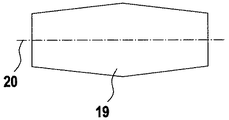
材料流12から異物を除去するための装置13は並べて配置または搬送方向Tに前後に並べて配置された多数の除去ローラ19を備えている。除去ローラ19は(図示していない)回転駆動装置によってそれぞれの回転軸線20回りに回転可能である。除去ローラ19の回転軸線20は互いに平行にかつ搬送方向Tに対して横方向に延びている。すべての除去ローラ19はそれぞれ隣接する除去ローラ19に対して間隔を有している。個々の除去ローラ19の間隔は同じにすることができる。しかし、可変の間隔が有利である。特に、除去ローラ19の間隔が搬送方向Tに向かって増大すると有利である。
The
装置13のすべての除去ローラ19の回転速度または搬送速度は同じであり、同期している。しかし、適切な制御手段および駆動手段により、各除去ローラ19または除去ローラグループのために別々の搬送速度を実現することができる。除去ローラ19の搬送速度と搬送要素14,15の搬送速度は互いに異なっている。好ましくは、除去ローラ19の搬送速度が搬送要素14,15の搬送速度よりも遅い。搬送要素14の搬送速度は除去ローラ19の搬送速度の約2〜3倍である。搬送要素15は搬送要素14よりも速い速度、好ましくは約2倍の速度を有する。しかし、特に単一層17の形成時の所望な結果に依存して、異なる速度比とすることができる。搬送要素16は図示した実施の形態では運転中、搬送要素15とほぼ同じ搬送速度を有する。しかし、特に空気流を発生するために設けられる搬送要素16は、搬送要素15の搬送速度と異なる搬送速度を有していてもよい。
The rotation speeds or conveying speeds of all the removing
後側の搬送要素15の範囲に、検出要素21を任意に配置することができる(特に図2参照)。検出要素21は特に単一層17内の金属(例えばアルミニウム箔)からなる異物を検出する働きをする。検出要素21は線状に形成され、搬送要素15の全幅にわたって延設されているので、単一層17をその全幅にわたって同期して検出可能である。
The
他の実施の形態では、セパレータ(空気分離器)として形成可能な付加的な篩22と、光学式検査要素18とが1つのユニットを形成している。篩22は検査要素18に直接付設されているかまたは検査要素のすぐ後に配置され、理想的には検査要素18の一体構成部品である。篩22は普通のようにおよび公知のように軽量部品または重量部品をふるいわけるように選択的に形成されているので、詳細な説明は省略する。
In another embodiment, the
明確に図示していない実施の形態では、除去ローラ19の間隔を搬送方向Tに向かって小さくすることができる。更に、除去ローラ19の形状と構造を変えることができる。図3a〜3cには選択された例だけが示してある。図3aには典型的な円筒状ローラ形状が示してある。直径が一端から中央の方へ増大し、反対側の端部の方に再び縮小している、図3bに示した中高ローラ形状は特に、搬送方向Tに対して横方向における材料流12の分配または均一化を改善する働きがある。同じことが図3cに示したローラ形状にも当てはまる。更に、1つの装置13において異なる複数のローラ形状を組み合わせることができる。除去ローラ19は互いに平行に配向する必要はなく、互いに角度をなして、例えば上から見てジグザグ状に配置可能である。図3dは、たばこを均一に分配する働きがある、除去ローラ19の形状の他の実施の形態を示している。各除去ローラ19は2個のローラ要素19a,19bに分割されている。ローラ要素19a,19bまたはその回転軸線20aまたは20bは互いに斜めに延びている。回転軸線20a,20bの交点の範囲において、被覆要素23を任意に設けることができる。この被覆要素は傾斜したローラ要素19a,19bの間の隙間を閉鎖している。
In an embodiment that is not clearly illustrated, the interval between the
次に、図1,2に基づいて方法の原理を詳しく説明する。1つまたは複数の装入個所から、生たばこがばらものとしてまたは他の方法で、供給装置11の全幅または所定の範囲に装入される。たばこは供給装置11によって厚層状の材料流12として搬送方向Tに搬送される。この層は異なる高さを有していてもよい。材料流12は装置13への移行部、すなわち例えば欧州特許出願第03090079.9号明細書に記載されているようなひも除去器への移行部において、除去ローラ19上に落下する。除去ローラ19の回転によって、材料流12は搬送方向Tに搬送され、その際予備分配される。これは、材料流12が引き伸ばされる、すなわち薄くなることを意味する。除去ローラ19の可変の間隔または搬送方向Tに大きくなる間隔によって、たばこは駆動される搬送要素14上に均一に落下する。搬送要素14上の材料流12は供給装置と比較して、特に除去ローラ19よりも搬送要素14の速度が速いことによって、既に大幅に薄くなっており、特にかなり均一化されている。例えば生たばこの包装材としてのジュート袋の糸のような、材料流12内の異物は、除去ローラ19によって捕えられ、それによって材料流12から除去される。
Next, the principle of the method will be described in detail with reference to FIGS. From one or more loading points, the tobacco is loaded as a bulk or otherwise into the full width or predetermined range of the
搬送要素14上にある材料流12は2段階で加速される。というのは、材料流12が第1の搬送速度v1 を有する搬送要素14から、第2の搬送速度v2 を有する搬送要素15に移送されるからである。この場合、v2 >v1である。搬送要素14から搬送要素15に移行する範囲において、材料流12は搬送要素15上に落下する。それによって、材料流12は単一層17を形成するために更に引き伸ばされる。単一層17は図示した実施の形態では、搬送要素16の駆動によって生じる空気流によって、搬送要素15上に保持される。単一層17は搬送要素15によって光学式検査要素18を通過する。この検査要素内で、不純物および/または異物が検出され、公知の方法で適切におよび直接的に分離除去される。
The
単一層17は光学式検査要素18に入る前に任意に検出可能である。この場合特に、金属部品が検出され、単一層17から分離除去される。検出されおよび/または光学的に検査され、不純物および/または異物を除去した単一層17は他の加工部に供給される。単一層17は搬送要素を経て篩22に供給される。そのために、単一層17すなわちたばこは搬送要素上に放物線状に落下する。しかし、単一層17が篩22に直接供給されると有利である。この場合、たばこは篩22に放物線状に直接落下する。顧客の要望に応じて、篩22において重量部品または軽量部品をふるいわけることができる。
The
図3b,3cに示した除去ローラ19を使用すると、材料流12が装置13の範囲にいおいて拡げられる。すなわち、材料流が特に除去ローラ19の外側エッジの特別な形状によって案内される。従って、搬送方向Tに対して横方向に材料流が引き伸ばされることによって均一化が達成される。
Using the
11 供給装置
12 材料流
13 異物除去装置
14 搬送要素
15 搬送要素
16 搬送要素
18 検査要素
19 除去ローラ
21 検出要素
22 篩
DESCRIPTION OF
Claims (24)
然るべき装置(13)によって材料流(12)から異物を除去し、
材料流(12)を加速する搬送要素(14)に材料流(12)を案内し、
光学式検査要素(18)によって他の異物を検出し、そして
たばこから異物を分離する、 加工すべきたばこから異物を取り除くための方法において、
材料流(12)がそれから異物を除去するための装置(13)によって、材料流(12)を加速する搬送要素(14)に直接案内され、搬送要素(14)への材料流(12)の供給が上側から行われることを特徴とする方法。 Supplying a material stream (12) consisting essentially of tobacco to an apparatus (13) for removing foreign matter from the tobacco to be processed;
Removing foreign matter from the material stream (12) by means of an appropriate device (13);
Guiding the material flow (12) to the conveying element (14) accelerating the material flow (12);
In a method for removing foreign matter from tobacco to be processed, detecting other foreign matter by means of an optical inspection element (18) and separating the foreign matter from the tobacco,
The material stream (12) is then guided directly by the device (13) for removing foreign matter to the conveying element (14) accelerating the material stream (12) and the material stream (12) to the conveying element (14) A method characterized in that the feeding is performed from above.
Applications Claiming Priority (1)
| Application Number | Priority Date | Filing Date | Title |
|---|---|---|---|
| DE102004008642A DE102004008642A1 (en) | 2004-02-19 | 2004-02-19 | Method and device for removing foreign substances from tobacco to be processed |
Publications (1)
| Publication Number | Publication Date |
|---|---|
| JP2005230010A true JP2005230010A (en) | 2005-09-02 |
Family
ID=34745253
Family Applications (1)
| Application Number | Title | Priority Date | Filing Date |
|---|---|---|---|
| JP2005042083A Withdrawn JP2005230010A (en) | 2004-02-19 | 2005-02-18 | Method and apparatus for removing foreign materials from tobacco to be processed |
Country Status (5)
| Country | Link |
|---|---|
| US (1) | US20050183734A1 (en) |
| EP (1) | EP1568288A1 (en) |
| JP (1) | JP2005230010A (en) |
| CN (1) | CN1656950A (en) |
| DE (1) | DE102004008642A1 (en) |
Cited By (1)
| Publication number | Priority date | Publication date | Assignee | Title |
|---|---|---|---|---|
| JP2022500043A (en) * | 2018-09-17 | 2022-01-04 | コマス−コストルツィオニ マッチネ スペシアリ−エセ.ピ.ア. | Methods and plants for the production of reconstructed tobacco |
Families Citing this family (8)
| Publication number | Priority date | Publication date | Assignee | Title |
|---|---|---|---|---|
| DE102009007481A1 (en) * | 2009-01-30 | 2010-09-02 | Fraunhofer-Gesellschaft zur Förderung der angewandten Forschung e.V. | Conveyor system for transporting materials, in particular bulk material |
| CN102389159B (en) * | 2011-07-22 | 2013-12-11 | 云南昆船设计研究院 | Method and device for removing impurities of tobacco leaves in pre-processing stage of threshing and redrying |
| PL2684471T3 (en) * | 2012-07-11 | 2016-04-29 | Hauni Maschinenbau Gmbh | Device for separating foreign bodies from a flow of tobacco |
| DE102014207157A1 (en) | 2014-02-28 | 2015-09-03 | Fraunhofer-Gesellschaft zur Förderung der angewandten Forschung e.V. | Conveying system, plant for bulk material sorting with such a conveyor system and transport method |
| CN105173632A (en) * | 2015-07-14 | 2015-12-23 | 山东中烟工业有限责任公司 | Material evenly-distributing device and method for improving purity degree of tobacco |
| CN109967344A (en) * | 2019-05-15 | 2019-07-05 | 云南吉星德亿科技有限公司 | A kind of processing unit (plant) promoting offal degree of purity |
| CN112495766B (en) * | 2020-11-07 | 2022-04-15 | 常德长岭机械制造科技有限公司 | Tobacco processing is with having raw materials screening plant who prevents blockking up mechanism |
| CN113955518B (en) * | 2021-11-16 | 2023-03-31 | 河南焦煤能源有限公司九里山矿 | Automatic homogenization feeder of control feed |
Family Cites Families (16)
| Publication number | Priority date | Publication date | Assignee | Title |
|---|---|---|---|---|
| US2676694A (en) * | 1950-10-10 | 1954-04-27 | Wyss | Apparatus for the uniform dispensing of pourable material, particularly shavings, chips, and fibrous material from storage bins |
| US2841154A (en) * | 1954-11-01 | 1958-07-01 | American Mach & Foundry | Cigarette machine feed |
| US2942607A (en) * | 1957-07-08 | 1960-06-28 | W I Skinner And Company | Machines for cleaning tobacco scrap |
| DE2609812A1 (en) * | 1976-03-10 | 1977-09-22 | Hauni Werke Koerber & Co Kg | Metal particles separator for tobacco processing industry - diverts tobacco batches into storage for screening and returns cleaned tobacco |
| CA1220394A (en) * | 1982-12-16 | 1987-04-14 | Rothmans Of Pall Mall Canada Limited | Tobacco winnowing device |
| GB8303412D0 (en) * | 1983-02-08 | 1983-03-16 | Amf Inc | Production of smoking material from cigarette winnowings |
| US4657144A (en) * | 1985-02-25 | 1987-04-14 | Philip Morris Incorporated | Method and apparatus for detecting and removing foreign material from a stream of particulate matter |
| FI90019C (en) * | 1991-12-10 | 1993-12-27 | Sunds Defibrator Rauma Woodhan | SAOLLNINGSFOERFARANDE OCH -ANORDNING |
| DE19505259A1 (en) * | 1995-02-16 | 1996-08-22 | Koehl Maschbau Gmbh | Device for removing long-fiber foreign matter from tobacco |
| DE59608838D1 (en) * | 1996-04-11 | 2002-04-11 | Dieffenbacher Schenck Panel | Process for the continuous production of a nonwoven for the production of wood-based panels or similar boards |
| ATE181683T1 (en) * | 1996-09-18 | 1999-07-15 | Bollegraaf Appingedam Maschf | SORTING CONVEYOR FOR SORTING WASTE PAPER FROM WASTE CARDBOARD |
| JP3041246B2 (en) * | 1996-11-15 | 2000-05-15 | 日本たばこ産業株式会社 | String removal device |
| IT1290732B1 (en) * | 1997-03-12 | 1998-12-10 | Pal Srl | ROLLER DEVICE FOR THE SEPARATION OF CHIPS AND PARTICLES WITH DIFFERENTIATED GRANULOMETRY AND USING FORMING MACHINE |
| DE19918774A1 (en) * | 1999-04-24 | 2000-10-26 | Hauni Maschinenbau Ag | Arrangement for forming monolayer from continuously delivered thick film material flow has conveyor belt cascade with at least two consecutive acceleration belts in delivery direction |
| ATE332088T1 (en) * | 1999-02-13 | 2006-07-15 | Hauni Maschinenbau Ag | ARRANGEMENT FOR FORMING A MONOLAYER FROM A CONTINUOUSLY SUPPLIED THICK-LAYER MATERIAL STREAM |
| DE10122971A1 (en) * | 2001-05-11 | 2002-11-14 | Siempelkamp Gmbh & Co | Spreading material system for spreading spreading material, in particular wood chips, wood fibers or the like on a spreading belt conveyor |
-
2004
- 2004-02-19 DE DE102004008642A patent/DE102004008642A1/en not_active Ceased
-
2005
- 2005-02-18 JP JP2005042083A patent/JP2005230010A/en not_active Withdrawn
- 2005-02-18 US US11/060,489 patent/US20050183734A1/en not_active Abandoned
- 2005-02-19 EP EP05090035A patent/EP1568288A1/en not_active Withdrawn
- 2005-02-21 CN CN200510008299.6A patent/CN1656950A/en active Pending
Cited By (2)
| Publication number | Priority date | Publication date | Assignee | Title |
|---|---|---|---|---|
| JP2022500043A (en) * | 2018-09-17 | 2022-01-04 | コマス−コストルツィオニ マッチネ スペシアリ−エセ.ピ.ア. | Methods and plants for the production of reconstructed tobacco |
| JP7512259B2 (en) | 2018-09-17 | 2024-07-08 | コマス-コストルツィオニ マッチネ スペシアリ-エセ.ピ.ア. | Method and plant for the production of reconstituted tobacco |
Also Published As
| Publication number | Publication date |
|---|---|
| DE102004008642A1 (en) | 2005-09-08 |
| EP1568288A1 (en) | 2005-08-31 |
| US20050183734A1 (en) | 2005-08-25 |
| CN1656950A (en) | 2005-08-24 |
Similar Documents
| Publication | Publication Date | Title |
|---|---|---|
| JP2005230010A (en) | Method and apparatus for removing foreign materials from tobacco to be processed | |
| KR101264510B1 (en) | Apparatus for handling capsules and capsule processing equipment including such an apparatus | |
| JP5328644B2 (en) | Transportation equipment | |
| JPH04211355A (en) | Method and apparatus for manufacturing filter tipped cigerette | |
| US20210368858A1 (en) | A replenishing device, an apparatus for manufacturing multi-segment rods and a method for manufacturing multi-segment rods | |
| JP3615791B2 (en) | Transfer device for forming a single-layer cigarette | |
| JP6109855B2 (en) | Sorting machine for sorting flat objects in a standing state using a plurality of imaging detection means | |
| JP2000237693A (en) | Apparatus for forming single layer from material flow of thick layer continuously supplied | |
| AU1484792A (en) | Method and apparatus for producing groups from different printed products | |
| JP2006111444A (en) | Chute for sorting/inspection apparatus | |
| US20060130858A1 (en) | Module for a machine and method for perforating rod-shaped articles of the tobacco industry | |
| WO2013190231A1 (en) | Method for screening products | |
| KR20070114165A (en) | Device and method for conveying rod-shaped articles | |
| EP1838464A1 (en) | Method and apparatus for sorting a gas-driven stream of generally flat and light-weight articles | |
| JP4993406B2 (en) | Flight sorter | |
| US7059478B2 (en) | Method and a device for the rejection of commodities | |
| US5803702A (en) | Vision inspection system for double stacked packs | |
| JP2007091395A (en) | Aligning device | |
| JPH08301435A (en) | Commodity array and supply device | |
| JP6840205B1 (en) | Rod-shaped body separator and image inspection device | |
| WO2013075791A1 (en) | Apparatus and method for deconstructing a smoking article | |
| JP3193397U (en) | Sorting device and sorting system using the same | |
| EP0941929A1 (en) | Vision inspection system for double stacked packs | |
| US20050268924A1 (en) | Cigarette maker | |
| KR102568342B1 (en) | Detection system |
Legal Events
| Date | Code | Title | Description |
|---|---|---|---|
| A300 | Application deemed to be withdrawn because no request for examination was validly filed |
Free format text: JAPANESE INTERMEDIATE CODE: A300 Effective date: 20080513 |