JP2005227566A - Lighting device and display device equipped with the same - Google Patents
Lighting device and display device equipped with the same Download PDFInfo
- Publication number
- JP2005227566A JP2005227566A JP2004036572A JP2004036572A JP2005227566A JP 2005227566 A JP2005227566 A JP 2005227566A JP 2004036572 A JP2004036572 A JP 2004036572A JP 2004036572 A JP2004036572 A JP 2004036572A JP 2005227566 A JP2005227566 A JP 2005227566A
- Authority
- JP
- Japan
- Prior art keywords
- columnar lens
- lens sheet
- columnar
- guide plate
- light guide
- Prior art date
- Legal status (The legal status is an assumption and is not a legal conclusion. Google has not performed a legal analysis and makes no representation as to the accuracy of the status listed.)
- Pending
Links
Images


Abstract
Description
本発明は、時計、携帯電話、オーディオ、電子機器等に使用される表示装置、及び表示装置に用いられる照明装置に関する。 The present invention relates to a display device used in a watch, a mobile phone, an audio, an electronic device, and the like, and a lighting device used in the display device.
近年、携帯機器、特に、携帯電話で用いる表示素子には小型軽量が要求されるため、液晶表示素子が多く使われている。しかし、液晶表示素子は受光型のため、暗い場所での視認性に問題がある。そこで、液晶表示素子の前面または背面に照明装置を設置することが多い。この薄型軽量を実現するため照明装置としては、光源としてLED(Light−Emitting−Diode)を導光板の側面に配したサイドライト型の照明装置が多用されている。 2. Description of the Related Art In recent years, liquid crystal display elements have been widely used because display elements used in portable devices, particularly mobile phones, are required to be small and light. However, since the liquid crystal display element is a light receiving type, there is a problem in visibility in a dark place. Therefore, an illuminating device is often installed on the front surface or the back surface of the liquid crystal display element. In order to realize this thin and light weight, a sidelight type lighting device in which an LED (Light-Emitting-Diode) is arranged as a light source on the side surface of the light guide plate is often used.
このような液晶表示装置に対して、微細な柱状構造が面内に複数本配列され、前記柱状構造の柱状中央領域はそれを取り巻く外周領域に比べて屈折率が高く形成され、厚さ方向に光を導く機能を有する柱状レンズシートである導光体シートの製造技術およびそれを用いた液晶表示装置が開示されている(例えば、特許文献1参照)。
特許文献1に開示されている柱状レンズシートを用いた従来の構成では、バックライトの導光板と柱状レンズシートとの間に拡散層を用いている。ところが、この拡散層がバックライトの導光特性に影響を与えてしまい、均一で高輝度な照明を行うことができないという課題を有していた。
In the conventional configuration using the columnar lens sheet disclosed in
本発明は、微細な柱状構造が面内に複数本配列され、前記柱状構造の柱状中央領域はそれを取り巻く外周環状領域に比べて屈折率が高く形成され、厚さ方向に光を導く機能を有する柱状レンズシートを導光板の光照射面側に複数枚接合し、それら柱状構造の配向方向の傾斜角を導光板側から順次小さくなるようにした。このような構造によって、良好な輝度と視角特性を持った照明装置を簡便に作製することが可能となる。 In the present invention, a plurality of fine columnar structures are arranged in a plane, and the columnar central region of the columnar structure is formed with a higher refractive index than the outer peripheral annular region surrounding it, and has a function of guiding light in the thickness direction. A plurality of the columnar lens sheets are joined to the light irradiation surface side of the light guide plate, and the inclination angle of the alignment direction of the columnar structures is made to decrease sequentially from the light guide plate side. Such a structure makes it possible to easily manufacture a lighting device having good luminance and viewing angle characteristics.
すなわち、本発明の照明装置は、透明材料で形成された平板状の導光板と、導光板の側端面から光を入射する光源と、導光板の光照射面側に設けられ、特定角度範囲で入射した光を散乱するとともにそれ以外の角度で入射された光を透過するレンズシートを備える照明装置であって、レンズシートは複数層設けられており、導光板に近いレンズシートほど特定角度範囲の中心角が導光板の光照射面に対して小さい角度であることとした。 That is, the illuminating device of the present invention is provided on a flat light guide plate formed of a transparent material, a light source for entering light from a side end surface of the light guide plate, and a light irradiation surface side of the light guide plate, and in a specific angle range. The illumination device includes a lens sheet that scatters incident light and transmits light incident at other angles, and the lens sheet is provided with a plurality of layers, and the lens sheet closer to the light guide plate has a specific angle range. The central angle is a small angle with respect to the light irradiation surface of the light guide plate.
あるいは、透明材料で形成された平板状の導光板と、導光板の側端面に配置された光源と、周囲の領域より屈折率の高い領域が厚み方向に連続的に形成された柱状レンズが面内に複数配列され、厚さ方向に光を導く機能を有する柱状レンズシートを複数枚備えるとともに、柱状レンズは、柱状レンズシートの面に立てた垂線の方向を基準として光源が配置された側と逆側に傾斜しており、柱状レンズシートの傾斜角は導光板に近い側の柱状レンズシートほど小さいこととした。さらに、柱状レンズシートは、導光板の上方に配置された第一柱状レンズシートと、第一柱状レンズシート上に積層された第二柱状レンズシートを備えるとともに、第一柱状レンズシートの柱状レンズの傾斜角が約20〜約45度であり、第二柱状レンズシートの柱状レンズの傾斜角が約0〜約25度であることとした。あるいは、柱状レンズシートは、導光板の上方に配置された第一柱状レンズシートと、第一柱状レンズシート上に積層された第二柱状レンズシートと、第二柱状レンズシート上に積層された第三柱状レンズシートを備えるとともに、第一柱状レンズシートの柱状レンズの傾斜角を約30〜約50度とし、第二柱状レンズシートの柱状レンズの傾斜角を約15〜約35度とし、第三柱状レンズシートの柱状レンズの傾斜角を約0〜約20度とした。 Alternatively, a flat light guide plate made of a transparent material, a light source arranged on the side end surface of the light guide plate, and a columnar lens in which a region having a higher refractive index than the surrounding region is continuously formed in the thickness direction A plurality of columnar lens sheets arranged in the thickness direction and having a function of guiding light in the thickness direction, and the columnar lens has a side on which a light source is disposed with reference to a direction of a perpendicular line standing on a surface of the columnar lens sheet; The columnar lens sheet is inclined in the opposite direction, and the inclination angle of the columnar lens sheet is smaller as the columnar lens sheet is closer to the light guide plate. Furthermore, the columnar lens sheet includes a first columnar lens sheet disposed above the light guide plate and a second columnar lens sheet laminated on the first columnar lens sheet, and the columnar lens of the first columnar lens sheet is provided. The inclination angle is about 20 to about 45 degrees, and the inclination angle of the columnar lens of the second columnar lens sheet is about 0 to about 25 degrees. Alternatively, the columnar lens sheet includes a first columnar lens sheet disposed above the light guide plate, a second columnar lens sheet stacked on the first columnar lens sheet, and a second columnar lens sheet stacked on the second columnar lens sheet. A third columnar lens sheet is provided, the inclination angle of the columnar lens of the first columnar lens sheet is about 30 to about 50 degrees, and the inclination angle of the columnar lens of the second columnar lens sheet is about 15 to about 35 degrees. The inclination angle of the columnar lens of the columnar lens sheet was about 0 to about 20 degrees.
さらに、導光板に最も近い柱状レンズシートと導光板との間に、導光板の屈折率よりも大きく、柱状レンズを構成する高屈折率領域の屈折率と略等しい屈折率を有する高屈折率層を設ける構成とした。また、高屈折率層として高屈折率接合剤を用いることとした。また、柱状レンズシートを構成する柱状レンズの配列を非周期的配列とした。 Further, a high refractive index layer having a refractive index larger than the refractive index of the light guide plate and substantially equal to the refractive index of the high refractive index region constituting the columnar lens, between the columnar lens sheet closest to the light guide plate and the light guide plate. It was set as the structure which provides. Further, a high refractive index bonding agent is used as the high refractive index layer. Further, the arrangement of the columnar lenses constituting the columnar lens sheet was an aperiodic arrangement.
また、本発明の表示装置は、上述の構成の照明装置を非自発光型の表示素子を照明するために備えることとした。 The display device of the present invention includes the illumination device having the above-described configuration for illuminating a non-self-luminous display element.
本発明によれば、良好な輝度と輝度分布を有する薄型軽量の照明装置を提供できるために、これを用いた液晶表示装置の表示品質が向上するのみならず、液晶表示装置の薄型軽量化をも実現できるという効果を有する。 According to the present invention, it is possible to provide a thin and light illumination device having good luminance and luminance distribution, so that not only the display quality of a liquid crystal display device using the same can be improved, but also the liquid crystal display device can be reduced in thickness and weight. Can also be realized.
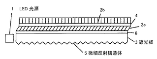
本発明の照明装置に関して図面を参照しながら説明する。図1は本発明の照明装置の構成を模式的に示す断面図である。導光板3の下面には微細反射構造体5が形成され、導光板3の上面には第一接合層4aと第二接合層4bを介して第一柱状レンズシート2aと第二柱状レンズシート2bが順に接合されている。LED光源1が導光板3の側面に配置されており、LED光源から出射した光は、導光板3の内部を導波され、導光板の照射面に到達する。導光板の照射面には上述したように柱状レンズシートが積層されているので、光源からの光は、第二柱状レンズシート面から図示されていない被照明体に面状一様に照射される。被照明体として、非自発光型の表示素子、例えば、液晶表示素子を用いることによって、輝度が均一で明るい薄型の液晶表示装置とすることができる。
The illumination device of the present invention will be described with reference to the drawings. FIG. 1 is a cross-sectional view schematically showing the configuration of the illumination device of the present invention. A fine reflecting structure 5 is formed on the lower surface of the
ここで、導光板3は、アクリル系樹脂やポリカーボネート系樹脂あるいはシクロオレフィン系樹脂などの透明な高分子で作られている。導光板3の下面に形成されている微細反射構造体5としては、図1の紙面に垂直な方向に稜線を持った微細プリズム群や、導光板内部に向かって凸または凹の互いに離間した微小三角柱群、あるいはシボ構造体を用いることができる。図1では1つしか描画されていないが、LED光源1は3から5個といった複数用いられるのが通常である。また、図示していないが、LED光源1に対向する導光板3の側面には、LED光源1から出射した光の導光板3内部での広がり角を制御するための微小プリズムが形成されている。この微小プリズムは図1における紙面上の上下方向の稜線を持っており、広がり角は微小プリズムの頂角および高さによって制御することができる。
Here, the
また、第一柱状レンズシート2aと第二柱状レンズシート2bは、微細な柱状構造が面内に複数本配列され、柱状構造内は周りの領域に比べて屈折率が高く形成されている。すなわち、周囲の領域より屈折率の高い領域が厚み方向に連続的に形成された柱状レンズが面内に複数配列されている。このような構成により、柱状レンズシートは厚さ方向に光を導く機能を有することになる。具体的には、屈折率が柱状構造の中心に向かうほど連続的に大きくなっているグレイディッドインデックス型柱状レンズ、または中心部分の屈折率がそれを取り巻く外周領域の屈折率よりも高い2層構造になっているステップインデックス型柱状レンズが複数配列されたフィルム構造になっている。グレイディッドインデックス型柱状レンズ、ステップインデックス型柱状レンズのいずれの場合においても、それらを構成する柱状レンズの光軸の方向を柱状レンズの配向方向と呼ぶことにする。本発明で用いる柱状レンズシートは、柱状レンズの配向方向が柱状レンズシートの面に立てた垂線の方向を基準としてLED光源1の配置されている側と逆側に傾斜して形成されている。柱状レンズシートの面に立てた垂線の方向に対して配向方向がなす角度を傾斜角と呼ぶことにする。
The first
第一柱状レンズシート2aは第二接合層4bによって第二柱状レンズシート2bと接合されている。第二柱状レンズシート2aは第一接合層4aによって導光板3と接合されている。これらの接合層としては、エポキシ系接着剤やアクリル系接着剤のような通常の光学接着剤層を用いても良いが、通常のフィルム粘着剤を用いるのが簡便である。
The first
図1において用いられている第一柱状レンズシート2aと第二柱状レンズシート2bとは、互いに異なった傾斜角を持っており、導光板3に接合された第一柱状レンズシート2aの傾斜角の方が第二柱状レンズシートより大きくなっている。具体的には、第一柱状レンズシート2aの傾斜角は20〜45度であり、第二柱状レンズシート2bの傾斜角は0〜25度となっている。このように、傾斜角の異なる2枚の柱状レンズシートを積層して接合することによって、柱状レンズシートを1枚しか用いない場合よりも導光板3からの光を効率良く照明することができる。
The first
また、導光板3と第一柱状レンズシート2aとの接合層4aとして、図3に示すように高屈折率接合層6を用いる構成とした。それによって、通常の接合層を用いる場合に比べて、導光板3から効率良く第一柱状レンズシート2aに光を伝えることが可能となり、その結果、本発明の照明装置の輝度を向上させることができる。通常の粘着剤では空気などの混合によって屈折率が低下しているが、高屈折率接合層6は接着剤または粘着剤に、高屈折率高分子材料または高屈折率酸化物超微粒子を混合したもので、高い屈折率が得られる。このとき、柱状レンズシート間の接合層4bとして高屈折率接合層を用いても良いことは言うまでもない。
Further, as the
図2に、柱状レンズシートが導光板上に3枚積層された構成の照明装置を示す。ここでは、第一柱状レンズシート2aの傾斜角は30〜50度、第二柱状レンズシート2bの傾斜角は15〜35度、第三柱状レンズシート2cの傾斜角は0〜20度である。このように柱状レンズシートを3枚にすることによって、柱状レンズシート2枚の場合に比べて構造は複雑になるが、より効率の高い照明を実現することができる。
FIG. 2 shows an illumination device having a configuration in which three columnar lens sheets are stacked on a light guide plate. Here, the inclination angle of the first
一般に、柱状レンズシートにおいては、後述するように、ある角度範囲でシートに入射された光は柱状レンズ内を導波して表面から散乱出射され、その角度範囲以外の角度で入射した光は柱状レンズシート内をほぼ直線透過して散乱を受けない。この散乱出射される光の入射角を散乱入射角、直線的に透過する光の入射角を直線透過角と呼ぶことにする。 In general, in a columnar lens sheet, as will be described later, light incident on the sheet within a certain angle range is guided through the columnar lens and scattered and emitted from the surface, and light incident at an angle other than the angle range is columnar. It passes through the lens sheet almost linearly and is not scattered. The incident angle of the scattered and emitted light is referred to as the scattering incident angle, and the incident angle of the linearly transmitted light is referred to as the linear transmission angle.
図4に、第一柱状レンズシート2aの導光板側表面に高屈折率層7が形成された構成の照明装置を示す。この高屈折率層7の屈折率は導光板3の屈折率よりも大きな値となっており、第一柱状レンズシートを構成している微細柱状レンズの高屈折領域の屈折率と同程度またはそれよりも小さい値を持っている。また、高屈折率層7の層厚は1〜5μm程度である。高屈折率層7の形成方法としては、CeO2やMgOとSiO2の材料混合物を真空蒸着で成膜しても良いし、シリカゾルとチタニアゾルの混合ゾルなどの屈折率を調整された混合ゾルを塗布焼成して形成しても良い。このようにして高屈折率層7が形成された第一柱状レンズシート2aは、高屈折率層7側を導光板3の照射面に向けて接合層4aで導光板3と接合されている。
FIG. 4 shows an illumination device having a configuration in which a high
この柱状レンズシートの製造は、例えば、屈折率の異なる2種類以上の光重合性化合物からなる液状反応層に、グラデーション加工を施したフォトマスクを介して傾斜角に対応した照射角で紫外線を照射することによって、光照射強度による光重合性化合物の光重合速度の違いを利用して屈折率の分布状態を制御することによって行う。 This columnar lens sheet is manufactured, for example, by irradiating a liquid reaction layer made of two or more kinds of photopolymerizable compounds having different refractive indexes with an irradiation angle corresponding to an inclination angle through a photomask subjected to gradation processing. Thus, the refractive index distribution is controlled by utilizing the difference in the photopolymerization rate of the photopolymerizable compound depending on the light irradiation intensity.
次に柱状レンズシート中の光の振舞いについて図5と図6とを用いて説明する。ここでは、簡単のため、図3に示したのと同様に柱状レンズシートを2枚用い、柱状レンズシートと導光板とは高屈折率接合層6を用いて接合した場合を説明する。図中に導光板3の内部からこれら柱状レンズシートに入射する光の光路の1つを矢印12で示してある。導光板3の中を導波している光は様々な入射角を持って高屈折率接合層6に入射するが、入射光の多くは導光板3の臨界角よりも大きな入射角を持って入射する。高屈折率接合層6は導光板3に比べて大きな屈折率を持っているために、高屈折率接合層6への屈折角はスネルの法則に従って入射角よりも小さくなる。 ステップインデックス型柱状レンズは、高屈折率領域14と低屈折率領域15とが明確な境界を持って形成されている。一方、グレイディッドインデックス型柱状レンズは、柱状レンズ中心軸付近の屈折率が最大になるような分布の高屈折率領域を持ち、その周りを最外周部の屈折率が最小となるような分布の低屈折率領域で覆われているが、ステップインデックス型柱状レンズのように高屈折率領域と低屈折率領域との間には明確な境界面を持っていない。ここでは、説明を簡単にするためにステップインデックス型柱状レンズシートを用いた場合について説明する。
Next, the behavior of light in the columnar lens sheet will be described with reference to FIGS. Here, for the sake of simplicity, a case where two columnar lens sheets are used in the same manner as shown in FIG. 3 and the columnar lens sheet and the light guide plate are bonded using the high refractive
ここで、柱状レンズ中央領域である高屈折率領域14の屈折率は高屈折率接合層6の屈折率と等しいかまたは大きい。従って、高屈折率接合層6から第一柱状レンズシートの高屈折率領域14に入射した光はそのまま直進するか、さらに導光板照射面の法線側に向かって屈折する。高屈折率領域14に入射した光は低屈折率領域15との境界面に入射するが、境界面への入射角は臨界角よりも大きな値となっているために光はこの境界面で全反射される。この光は高屈折率領域14と低屈折率領域15との境界面で繰り返し全反射して上方に導波していき、第一柱状レンズシートの上面から出射される。第一柱状レンズシートの内部上面への入射角は、柱状レンズ内の境界面で光が反射されることによって臨界角よりも小さな値となっているために柱状レンズシートの外部に出射される。
Here, the refractive index of the high
このとき、導光板3側の第一柱状レンズシート2aの層厚と高屈折率領域14への光の入射角と入射位置によって第一柱状レンズシート2aからの光の出射方向すなわち散乱角が定まる。
At this time, the light emission direction, that is, the scattering angle, of the light from the first
このようにして接合層4に入った光は、出射面側の第二柱状レンズシート2bに入射する。図5では第二柱状レンズシート2bの高屈折率領域14に入射するように書かれているが、柱状レンズシート2aと2bの接合がずれている場合は、低屈折率領域15に入射する場合もある。どちらの場合においても、第一柱状レンズシート2aからの光の出射角が第二柱状レンズシート2bの散乱入射角にある場合は、光は図5に示すように、第二柱状レンズシート2bの高屈折率領域14内を導波して表面から散乱出射される。また、第一柱状レンズシート2aからの光の出射角が第二柱状レンズシート2bの直線透過角の範囲内にある場合は、第二柱状レンズシート2bへの入射角も直線透過角となり、第二柱状レンズシート2bの表面で全反射されて再び導光板3側に戻る。
The light entering the
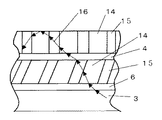
次に、導光板3の内部から高屈折率接合層6にさらに大きな入射角で入射してきた光が第一柱状レンズシート2aの高屈折率領域14に入射する場合を図6に示す。この場合、図中の光路16で示されているように、第一柱状レンズシート2aの高屈折率領域14と低屈折率領域15との境界面に入射する光の入射角は、図5の場合に比べて小さくなる。その結果、光は境界面を透過して低屈折率領域15に進入し第一柱状レンズシート2aの表面からは接合層4の内部にほぼ直線的に出射される。この場合、図6に示すように、光は接合層4から第二柱状レンズシート2bに直線透過角で入射し、第二柱状レンズシート2bの表面で全反射されて再び導光板3側に戻る。図5と図6において、第一柱状レンズシート2aを構成する柱状レンズは、その面に立てた垂線に対してLED光源と反対側に傾斜角20〜45度の範囲で傾いて配向している。また、その散乱入射角は10〜45度の範囲を持たせることができる。一方、導光板3の内部を導波する光の成分は、導光板3の臨界角である約43度以上の大きな入射角でLED光源側に傾斜して伝播する成分が多数を占めている。このような状況においても第一柱状レンズシート2aを構成する柱状レンズが上記のように傾斜しているために、少なくとも第一柱状レンズシート2aへの入射角が約43度以上で導光板3内部を伝播した光の一部は散乱入射角で入射させることができる。もちろん、傾斜角が25度と小さな場合は、散乱入射角が18度以上の第一柱状レンズシート2aを用いなければならない。
Next, FIG. 6 shows a case where light that has entered the high refractive
一方このとき、第二柱状レンズシート2bへの光の入射角は、およそ−20〜90度となる。それらの光の内、第二柱状レンズシート2bの散乱入射角で入射した光は0〜25度の傾斜角を持った第二柱状レンズシート2b内を導波して、その傾斜角方向に散乱出射される。
On the other hand, at this time, the incident angle of the light to the second
なお、グレイディッドインデックス型柱状レンズの内部に入射した光は、高屈折率領域14と低屈折率領域15の境界で反射されるのではなく、柱状レンズ内を光が導波するとき、より屈折率の高い方へと光路を曲げられる。従って、この柱状レンズの中での光路は滑らかな曲線を示す。しかし、この場合においても、ステップインデックス型柱状レンズの場合と同様に、散乱出射角が存在する。すなわち、散乱出射角よりも小さな入射角で入射した光は柱状レンズ内を導波して柱状レンズシートの表面から散乱出射されるが、散乱出射角よりも大きな入射角で入射した光はほぼ直進し柱状レンズシートの表面で全反射され再び導光板3の方に戻る。すなわち、そのような入射角は直線透過角に対応する。
Note that the light incident on the inside of the graded index columnar lens is not reflected at the boundary between the high
また、ステップインデックス型柱状レンズシートやグレイディッドインデックス型柱状レンズシートに関わらず、高屈折率領域と低屈折率領域との屈折率差あるいは屈折率変化量を調節することによって、散乱出射角は10〜45度程度の任意の角度とすることができる。 Regardless of the step index type columnar lens sheet or the graded index type columnar lens sheet, the scattering emission angle is set to 10 by adjusting the refractive index difference or the refractive index change amount between the high refractive index region and the low refractive index region. It can be set to an arbitrary angle of about 45 degrees.
本発明の照明装置においては、柱状レンズのレンズ径が、1μm〜250μm、レンズ高さ(柱状レンズシート層厚)が10μm〜200μmの柱状レンズシートを用いることができる。しかしながら、製造歩留まりや光利用効率あるいはハンドリングのし易さなどを考慮すると、レンズ径は5μm〜100μm、レンズ高さは20μm〜80μmとするのが好ましい。また、柱状レンズの屈折率差は0.01〜0.05のものを用いることができる。 In the illumination device of the present invention, a columnar lens sheet having a columnar lens with a lens diameter of 1 μm to 250 μm and a lens height (columnar lens sheet layer thickness) of 10 μm to 200 μm can be used. However, considering the production yield, light utilization efficiency, ease of handling, etc., the lens diameter is preferably 5 μm to 100 μm, and the lens height is preferably 20 μm to 80 μm. In addition, a columnar lens having a refractive index difference of 0.01 to 0.05 can be used.
次に、図2に示した照明装置においては、第一柱状レンズシート3a、第二柱状レンズシート3bおよび第三柱状レンズシート3cが順に接合層4a、4b、4cによって導光板に接合されている。これらの柱状レンズシートを構成する柱状レンズの傾斜角は、第一柱状レンズシート4aが30〜50度、第二柱状レンズシート2bが15〜35度、第三柱状レンズシートが0〜25度となっている。このように、柱状レンズシートを3枚積層することによって、図5と図6とで説明したのと同様の理由によって、導光板3の内部を伝播する光を効率良く第三柱状レンズシート2cの表面から照射することができる。特にこの場合、図1の場合と比べて、第一柱状レンズシート2aの傾斜角を大きく取ることができるために、導光板3の内部を伝播するより広い入射角成分を持った光を導光板3の外部に取り出すことができる上に、各柱状レンズシートの散乱入射角の範囲を30度程度に小さくすることができる。その結果、図1に示した構成の照明装置よりも、輝度を向上させることができ、効率良く光を視角方向に出射することができる。
Next, in the illumination device shown in FIG. 2, the first columnar lens sheet 3a, the second columnar lens sheet 3b, and the third columnar lens sheet 3c are sequentially bonded to the light guide plate by the
次に、本発明の照明装置を用いた表示装置について説明する。非自発光型の表示素子として液晶表示素子と照明装置を用いた液晶表示装置における光路の1例を図7に基づき説明する。本発明による液晶表示装置は、LED光源1、導光板3、第一柱状レンズシート2a、第二柱状レンズシート2b、高屈折率接合層6、接合層4、反射板11とからなる照明装置と、液晶パネル10とから構成される。また、導光板3の裏面には微細反射構造体5が形成されている。図中、照明装置内部を伝播する光の光路を矢印18と19で示してある。
Next, a display device using the illumination device of the present invention will be described. An example of an optical path in a liquid crystal display device using a liquid crystal display element and a lighting device as a non-self-luminous display element will be described with reference to FIG. The liquid crystal display device according to the present invention includes an illumination device including an
LED光源1から出射された光は、導光板3の内部に入った後、高屈折率接合層6を透過して、第一柱状レンズシート2a、接合層4、第二柱状レンズシート2bに順に入射する。このとき、第二柱状レンズシートの散乱入射角の範囲内で第二柱状レンズシート2bに光が入射すると、その光は矢印18で示すように第二柱状レンズシート2b内を導波して表面から散乱放出される。また、矢印19で示したように、第二柱状レンズシート2bの直線透過角でその光が入射した場合は、そのまま第二柱状レンズシート2bの表面で全反射して、再び接合層4、第一柱状レンズシート2a、高屈折率接合層6を順に透過して導光板3の内部に戻る。導光板3に戻った光は裏面の微細反射構造体5で偏向されて導光板3の裏面から抜け、反射板11で反射されて再び導光板3に戻る。この戻り光は偏向を受けているために、高屈折率接合層6を透過した後、再び第一柱状レンズシート2aに入射するときは、その入射角が第一柱状レンズシート2aの直線透過角になっている。そのために、第一柱状レンズシート2a内を直線透過した後、接合層4を経て第二柱状レンズシート2bに入射する。この光は第二柱状レンズシート2bの散乱入射角となっているために、第二柱状レンズシート2b内を導波して表面から散乱出射され、液晶パネル10を裏面から照明する。なお、ここでは頂角が100度程度以下で形成された微細プリズム構造体や導光板表面から凸状に突起した微細反射構造体を用いた場合を説明した。しかし、頂角が100度程度以上で形成された微細プリズム構造体や導光板表面から凹状に内部に窪んだ微細反射構造体を用いた場合は、上記戻り光の多くが微細反射構造体5で直接液晶パネル側に反射される。
The light emitted from the LED
このようにして第二柱状レンズシート2bの表面から照射された光は散乱されているため、より均一な照明となる上に、散乱入射角によって規制される指向性のために効率的に液晶パネルを照射することができる。したがって、視角特性に優れた明るい照明装置とすることができる。
Since the light irradiated from the surface of the second
さらに、第二柱状レンズシート2bと液晶パネル10との間に、レンズシート側の片面に微細プリズム構造体を設けたプリズムシートを1枚または2枚配置すれば、散乱光の指向性をさらに垂直方向に変換することができることとなり、より効率的な照明が可能となる。
Furthermore, if one or two prism sheets having a fine prism structure on one side on the lens sheet side are arranged between the second
次に、柱状レンズシートを構成する柱状レンズの充填密度について説明する。上記のように本発明に用いた柱状レンズシートは、導光板内を伝播する光を効率良く散乱出射するために、柱状レンズシートを構成する柱状レンズの充填密度をシート内で一様に配置すると、LED光源側の輝度が大きくなりすぎて輝度分布が悪くなってしまう。このような柱状レンズシートの特徴を用いて、本発明の照明装置においては、導光板のLED光源に近い側の柱状レンズ充填密度よりも遠い側の柱状レンズ充填密度の方が大きくなるように形成して得た柱状レンズシートを用いた。なお、本発明では複数の柱状レンズシートを用いているため、柱状レンズシートが重畳している部分の重点密度がほぼ同一になるように接合した。このようにすることによって、柱状レンズ充填密度が一様な柱状レンズシートを用いた場合よりもLED光源からの光を均一に被照明体に照射することができる。なお、このとき導光板3の裏面には微細プリズム構造などの微細反射構造体を形成してもしなくてもよい。しかし、導光板3の裏面に微細反射構造体を形成した方が輝度の均一性と光利用効率は向上する。この微細反射構造体の形成密度やピッチは、上記柱状レンズシートの柱状レンズ充填密度分布に対して最適化をはかって形成される。
Next, the filling density of the columnar lenses constituting the columnar lens sheet will be described. As described above, the columnar lens sheet used in the present invention has a uniform packing density of the columnar lenses constituting the columnar lens sheet in order to efficiently scatter and emit light propagating in the light guide plate. The luminance on the LED light source side becomes too large and the luminance distribution becomes worse. Using such a feature of the columnar lens sheet, in the lighting device of the present invention, the columnar lens filling density on the far side is larger than the columnar lens filling density on the side closer to the LED light source of the light guide plate. The columnar lens sheet obtained as described above was used. In the present invention, since a plurality of columnar lens sheets are used, the portions where the columnar lens sheets are superimposed are joined so that the weight density is substantially the same. By doing in this way, the to-be-illuminated body can be irradiated with light from the LED light source more uniformly than when a columnar lens sheet having a uniform columnar lens filling density is used. At this time, a fine reflecting structure such as a fine prism structure may or may not be formed on the back surface of the
図8に柱状レンズシートの柱状レンズ充填密度を変化させた例を示す。この図は、本発明の照明装置を柱状レンズシート側から見た平面図であり、LED光源1a、1b、1cが導光板側面に3個配置されている。柱状レンズシート2には柱状レンズ12が充填して複数配列されている。図示するように、LED光源側の柱状レンズのレンズ径がLED光源から離れるに従って小さくなるように配列することによって、柱状レンズの充填密度を変化させている。図を見やすくするように誇張されて描かれているが、柱状レンズ径は、およそ5μm〜200μmまでの大きさで分布しており、その値は導光板サイズや図示されていない導光板や高屈折率層の屈折率、および柱状レンズの層厚や屈折率によって最適値は変化する。また、柱状レンズシート2面内での配列はモアレ縞の発生を防ぐために、周期性を除去した配列になっている。
FIG. 8 shows an example in which the columnar lens filling density of the columnar lens sheet is changed. This figure is the top view which looked at the illuminating device of this invention from the columnar lens sheet side, and three LED light sources 1a, 1b, and 1c are arrange | positioned at the light-guide plate side surface. A plurality of
また、図9に柱状レンズシートの柱状レンズ充填密度を変化させた他の構成を示す。この構成では、LED光源1a、1b、1cから離れるに従って柱状レンズの配置されている列密度を変化させて充填密度が変わるように配列されている。具体的には柱状レンズはLED光源の配列方向に一列に並んだ列単位で配列されており、この列密度がLED光源に近い側は密に、LED光源から離れるに従って疎になっている。本最良形態では、LED光源から離れるに従って列間の距離が二次関数的に狭くなるように配列してある。充填密度の変化のさせ方は、図9に示した以外にも、柱状レンズの列間隔を一定にしておき、列内での柱状レンズの配列密度を列がLED光源に近くなるほど疎になるようにしてもよいし、これと図8に示した方法を併用しても良い。 FIG. 9 illustrates another configuration in which the columnar lens filling density of the columnar lens sheet is changed. In this structure, it arranges so that the packing density may change by changing the column density in which the columnar lenses are arranged as the distance from the LED light sources 1a, 1b, and 1c increases. Specifically, the columnar lenses are arranged in units of rows arranged in a row in the arrangement direction of the LED light sources, and the side where the column density is close to the LED light sources is denser and becomes sparse as the distance from the LED light sources is increased. In this best mode, the distance between the columns is arranged so as to become a quadratic function as the distance from the LED light source increases. In addition to the method shown in FIG. 9, the packing density is changed by keeping the column spacing of the columnar lenses constant, and the arrangement density of the columnar lenses in the column becomes sparser as the column gets closer to the LED light source. Alternatively, this and the method shown in FIG. 8 may be used in combination.
図9に示す構成では列中の柱状レンズは全て同じ径で、同じ屈折率差を持っている。しかし、LED光源1a、1b、1c方向の輝度分布を調節するために、列の内部で光強度の弱い領域の柱状レンズの充填密度が大きくなるように柱状レンズ径を列内で変化させてもよい。このようにすることによって、照明装置全体での輝度分布を向上させることができるばかりでなく、LED光源方向のモワレ縞の発生を防ぐことができる。図9のような重点密度の変化のさせ方をする場合は、複数の柱状レンズシートを構成する柱状レンズ同士が互いに重なり合うように厳密に位置を合わせて接合する必要がある。 In the configuration shown in FIG. 9, all the columnar lenses in the row have the same diameter and the same refractive index difference. However, in order to adjust the luminance distribution in the LED light sources 1a, 1b, and 1c, the columnar lens diameter may be changed within the column so that the filling density of the columnar lenses in the region with low light intensity within the column is increased. Good. By doing in this way, not only the luminance distribution in the whole lighting device can be improved, but also the occurrence of moire fringes in the LED light source direction can be prevented. In the case of changing the importance density as shown in FIG. 9, it is necessary to strictly align and join the columnar lenses constituting the plurality of columnar lens sheets so that they overlap each other.
図10に本発明で用いた柱状レンズシートの光透過特性を示す。図10において、横軸は柱状レンズシートへの光の入射角、縦軸は光透過強度を表している。図中、傾斜角が0度の柱状レンズシートの特性曲線20と、傾斜角がα度の柱状レンズシートの特性曲線21を表している。ただし、測定雰囲気は大気中であり、柱状レンズシート単体で評価した場合を示してある。特性曲線20では、柱状レンズシートは角度±βで光強度がほぼゼロになっていることがわかる。入射角が−β〜βの範囲内では光は散乱透過され、入射角の絶対値がβ以上の範囲内では光は散乱されずに直進透過する。すなわち、βは散乱入射角である。
一方、柱状レンズの配向方向をα度だけ傾けた場合の特性曲線21は、配向方向が0度の場合に比べて、散乱入射角がそのままα度だけずれた位置にシフトする。そのとき、散乱入射角の範囲はほとんど変化なく、α−β〜α+βの範囲内にシフトするだけである。従って、図10に示す特性曲線21においては、角度αで入射した光は透過時に散乱を受けるが角度−αで入射した光は散乱を受けずに直線透過する。すなわち、この柱状レンズシートを導光板に貼り付けたとき、角度−αで入射した光は、もしαが臨界角よりも大きければ、柱状レンズシートの出射面で全反射して再び導光板の方に戻って行く。
FIG. 10 shows the light transmission characteristics of the columnar lens sheet used in the present invention. In FIG. 10, the horizontal axis represents the incident angle of light to the columnar lens sheet, and the vertical axis represents the light transmission intensity. In the figure, a
On the other hand, the
図10において、柱状レンズの傾斜角が0度である特性曲線20の場合を考える。このとき、導光板からβ〜−βの角度で入射した照明光は、柱状レンズ内を伝播して表面から散乱照射される。しかし、γをβよりも大きく、臨界角よりも大きな角度とすると、入射角γで入射した光は柱状レンズシートの出射面で全反射して再び導光板内部に戻り照明に寄与することはない。また、導光板内部を伝播する光の多くは約43度以上の大きな入射角を持って柱状レンズシートに入射するため、これを効率良く利用するためには柱状レンズシートの散乱入射角を45度程度の大きな値に設定するか、もしくは導光板に形成する微小反射構造体をそれからの反射光が柱状レンズシートに対して垂直に反射するように構成することが望ましい。
In FIG. 10, the case of the
次に、配向方向がαだけ傾いた柱状レンズシートを用いた特性曲線21を考える。まず、入射角α−β〜α+βの入射角度範囲で導光板から入射した光は散乱して出射される。また、それ以外の入射角度範囲で導光板から入射した光は、柱状レンズシートの表面で全反射されて再び導光板内部に戻って行く。βの値は、柱状レンズシートの層厚、柱状レンズの口径、あるいは柱状レンズの屈折率差などを調整することによって、10〜45度程度までの任意の値に制御することができる。また、配向方向αの値は、製造時の光照射角度を傾斜させることによって、0〜50度程度の任意の角度に設定することができる。従って、導光板から約43度の入射角を持った照明光が入射した場合に、αの値を10〜50度とすることによって効率良く柱状レンズシートの表面から出射させることができる。
Next, consider a
以上の説明において、導光板上に接合する柱状レンズシートの枚数が2枚と3枚の場合を説明したが、その枚数を4枚以上としても良いことは言うまでもない。 In the above description, the case where the number of columnar lens sheets joined on the light guide plate is two and three has been described, but it goes without saying that the number may be four or more.
以下に、本発明の実施例を具体的に説明する。 Examples of the present invention will be specifically described below.
図1に示す構成の照明装置を以下のとおり作製した。35mm×43mm×0.7mmのアクリル性導光板の表面に通常の粘着剤を用いて柱状レンズシートを2枚貼り付けた。その導光板のサイドに3本のLED光源を配置した。第一柱状レンズシートとしては、散乱入射角45度で傾斜角45度のグレイディッドインデックス型柱状レンズを一様に配列したものを用いた。第二柱状レンズシートとしては、散乱入射角45度で傾斜角15度のものを用いた。また、これら2枚の柱状レンズシートの厚みは70μm、柱状レンズ径としては30μmのものを用いた。一方、上記と同一の導光板に上記と同じ第一柱状レンズシートだけを貼り付けたものを比較用試料とした。 The lighting device having the configuration shown in FIG. 1 was produced as follows. Two columnar lens sheets were attached to the surface of an acrylic light guide plate having a size of 35 mm × 43 mm × 0.7 mm using a normal adhesive. Three LED light sources were arranged on the side of the light guide plate. As the first columnar lens sheet, a graded index columnar lens having a scattering incident angle of 45 degrees and an inclination angle of 45 degrees was used. A second columnar lens sheet having a scattering incident angle of 45 degrees and an inclination angle of 15 degrees was used. The thickness of these two columnar lens sheets was 70 μm, and the columnar lens diameter was 30 μm. On the other hand, a sample for comparison was prepared by attaching only the same first columnar lens sheet as described above to the same light guide plate as described above.
LED光源を点灯した時に、作製した導光板から出射される光の出射角と輝度との関係を測定し図11に示した。図11では、比較用試料を用いた場合の結果を曲線23に、本発明の試料を用いた場合の結果を曲線22に示してある。この結果から分かるように比較用試料では0度と45度の2箇所に輝度ピークが現れているが、本発明の試料においては15度に大きな輝度ピークと0度と60度に小さなピークがあることが分かる。0度のピークは導光板からの0度の反射光成分が直線透過して出現したものであり、60度のピークは第一柱状レンズシートからの散乱光のうち第二柱状レンズシートに対する直線入射角となった光が原因と考えられる。また、本発明の試料の方が、比較試料よりも約15%総光量が多くなった。
When the LED light source was turned on, the relationship between the emission angle of light emitted from the produced light guide plate and the luminance was measured and shown in FIG. In FIG. 11, the result when the comparative sample is used is shown as a
このように本発明の試料は、視角方向である15度の方向に輝度が高いために、視感においては比較試料より明るく感じた。 Thus, since the brightness | luminance was high in the direction of 15 degree | times which is a visual angle direction, the sample of this invention felt brighter than the comparative sample in visual sense.
図2に示す構成の照明装置を以下のとおり作製し、試料とした。35mm×43mm×0.7mmのアクリル性導光板の表面に通常の粘着剤を用いて柱状レンズシートを3枚貼り付けた。その導光板のサイドに3本のLED光源を配置した。第一柱状レンズシートとしては、散乱入射角30度で傾斜角45度のグレイディッドインデックス型柱状レンズを一様に配列したものを用いた。第二柱状レンズシートとしては、散乱入射角30度で傾斜角30度のグレイディッドインデックス型柱状レンズを一様に配列したものを用いた。第三柱状レンズシートとしては、散乱入射角30度で傾斜角15度のものを用いた。また、これら3枚の柱状レンズシートの厚みは70μm、柱状レンズ径としては30μmのものを用いた。一方、この試料と実施例1で作製した試料とを比較した。 A lighting device having the configuration shown in FIG. 2 was produced as follows and used as a sample. Three columnar lens sheets were attached to the surface of an acrylic light guide plate of 35 mm × 43 mm × 0.7 mm using a normal adhesive. Three LED light sources were arranged on the side of the light guide plate. As the first columnar lens sheet, a graded index columnar lens having a scattering incident angle of 30 degrees and an inclination angle of 45 degrees was used. As the second columnar lens sheet, a graded index columnar lens having a scattering incident angle of 30 degrees and an inclination angle of 30 degrees was used. As the third columnar lens sheet, one having a scattering incident angle of 30 degrees and an inclination angle of 15 degrees was used. The thickness of these three columnar lens sheets was 70 μm, and the columnar lens diameter was 30 μm. On the other hand, this sample was compared with the sample produced in Example 1.
LED光源を点灯した時に、作製した導光板から出射される光の出射角と輝度との関係を測定し図12に示した。図中、実施例1の試料を用いた場合の結果を曲線22に、本実施例の試料を用いた場合の結果を曲線24に示してある。この結果から分かるように、実施例1の試料に存在していた60度近傍の輝度ピークは本実施例の試料においては消失していることが分かる。また、0度と15度のピークはより高くなっていることも分かる。このことは、3枚の柱状レンズシート間で散乱による光の散逸が少なくなっていることを示している。その結果、本実施例で作製した試料の方が、実施例1の試料よりもさらに約8%総光量が多くなった。
When the LED light source was turned on, the relationship between the emission angle of light emitted from the produced light guide plate and the luminance was measured and shown in FIG. In the figure, the result when the sample of Example 1 is used is shown as a
このように本実施例の試料は、視角方向である15度の方向に輝度が高いために、視感においては比較試料より明るく感じた。 Thus, since the sample of this example had high brightness in the direction of the viewing angle of 15 degrees, it felt brighter than the comparative sample.
実施例1の構成において、図4に示すように第一柱状レンズシートの表面に高屈折率層を設けた照明装置を作製した。本実施例では、シリカゾルを主剤として酸化アンチモンゾルあるいは酸化チタンゾルを混合したものを塗布した後焼成して、屈折率1.52で膜厚5μmの高屈折率層を形成した。その結果、上述した実施例1と2よりも、作製した照明装置の輝度がさらに5〜11%高くなった。 In the configuration of Example 1, as shown in FIG. 4, an illumination device in which a high refractive index layer was provided on the surface of the first columnar lens sheet was produced. In this example, a mixture of antimony oxide sol or titanium oxide sol containing silica sol as a main component was applied and baked to form a high refractive index layer having a refractive index of 1.52 and a thickness of 5 μm. As a result, the brightness of the manufactured lighting device was further increased by 5 to 11% compared to Examples 1 and 2 described above.
1 LED光源
2a 第一柱状レンズシート
2b 第二柱状レンズシート
2c 第三柱状レンズシート
3 導光板
4、4a、4b、4c 接合層
5 微細反射構造体
6 高屈折率接合層
7 高屈折率層
10 液晶パネル
11 反射板
12 柱状レンズ
14 高屈折率領域
15 低屈折率領域
DESCRIPTION OF
Claims (8)
前記導光板の側端面から光を入射する光源と、
前記導光板の光照射面側に設けられ、特定角度範囲で入射した光を散乱するとともにそれ以外の角度で入射された光を透過するレンズシートを備える照明装置であって、
前記レンズシートは複数層設けられており、前記導光板に近いレンズシートほど前記特定角度範囲の中心角が前記導光板の光照射面に対して小さい角度であることを特徴とする照明装置。 A flat light guide plate formed of a transparent material;
A light source for entering light from a side end surface of the light guide plate;
An illumination device comprising a lens sheet that is provided on the light irradiation surface side of the light guide plate and scatters light incident at a specific angle range and transmits light incident at other angles,
The lens sheet is provided with a plurality of layers, and the lens sheet closer to the light guide plate has a smaller central angle of the specific angle range with respect to the light irradiation surface of the light guide plate.
前記導光板の側端面に配置された光源と、
周囲の領域より屈折率の高い領域が厚み方向に連続的に形成された柱状レンズが面内に複数配列され、厚さ方向に光を導く機能を有する柱状レンズシートを複数枚備えるとともに、
前記柱状レンズは、前記柱状レンズシートの面に立てた垂線の方向を基準として前記光源が配置された側と逆側に傾斜しており、前記柱状レンズシートの傾斜角は導光板に近い側の柱状レンズシートほど小さいことを特徴とする照明装置。 A flat light guide plate formed of a transparent material;
A light source disposed on a side end surface of the light guide plate;
A plurality of columnar lenses in which a region having a higher refractive index than the surrounding region is continuously formed in the thickness direction are arranged in a plane, and a plurality of columnar lens sheets having a function of guiding light in the thickness direction are provided.
The columnar lens is inclined to the side opposite to the side where the light source is arranged with reference to the direction of the perpendicular line standing on the surface of the columnar lens sheet, and the inclination angle of the columnar lens sheet is closer to the light guide plate. An illumination device characterized in that the columnar lens sheet is smaller.
前記第一柱状レンズシートの柱状レンズの傾斜角が約30〜約50度であり、前記第二柱状レンズシートの柱状レンズの傾斜角が約15〜約35度であり、前記第三柱状レンズシートの柱状レンズの傾斜角が約0〜約20度であることを特徴とする請求項2に記載の照明装置。 The columnar lens sheet is stacked on the first columnar lens sheet disposed above the light guide plate, the second columnar lens sheet stacked on the first columnar lens sheet, and the second columnar lens sheet. And a third columnar lens sheet,
The inclination angle of the columnar lens of the first columnar lens sheet is about 30 to about 50 degrees, the inclination angle of the columnar lens of the second columnar lens sheet is about 15 to about 35 degrees, and the third columnar lens sheet The illumination apparatus according to claim 2, wherein an inclination angle of the columnar lens is about 0 to about 20 degrees.
Priority Applications (1)
| Application Number | Priority Date | Filing Date | Title |
|---|---|---|---|
| JP2004036572A JP2005227566A (en) | 2004-02-13 | 2004-02-13 | Lighting device and display device equipped with the same |
Applications Claiming Priority (1)
| Application Number | Priority Date | Filing Date | Title |
|---|---|---|---|
| JP2004036572A JP2005227566A (en) | 2004-02-13 | 2004-02-13 | Lighting device and display device equipped with the same |
Publications (2)
| Publication Number | Publication Date |
|---|---|
| JP2005227566A true JP2005227566A (en) | 2005-08-25 |
| JP2005227566A5 JP2005227566A5 (en) | 2007-03-29 |
Family
ID=35002320
Family Applications (1)
| Application Number | Title | Priority Date | Filing Date |
|---|---|---|---|
| JP2004036572A Pending JP2005227566A (en) | 2004-02-13 | 2004-02-13 | Lighting device and display device equipped with the same |
Country Status (1)
| Country | Link |
|---|---|
| JP (1) | JP2005227566A (en) |
Cited By (5)
| Publication number | Priority date | Publication date | Assignee | Title |
|---|---|---|---|---|
| JP2012141593A (en) * | 2010-12-16 | 2012-07-26 | Lintec Corp | Light diffusion film and manufacturing method for light diffusion film |
| JP2013019988A (en) * | 2011-07-08 | 2013-01-31 | Mitsubishi Rayon Co Ltd | Light control film |
| JP2013195672A (en) * | 2012-03-19 | 2013-09-30 | Tomoegawa Paper Co Ltd | Anisotropic optical film |
| WO2014156420A1 (en) * | 2013-03-29 | 2014-10-02 | リンテック株式会社 | Light diffusion film and light diffusion film manufacturing method |
| WO2014156421A1 (en) * | 2013-03-29 | 2014-10-02 | リンテック株式会社 | Light diffusion film and light diffusion film manufacturing method |
Citations (9)
| Publication number | Priority date | Publication date | Assignee | Title |
|---|---|---|---|---|
| JPH09184921A (en) * | 1995-12-28 | 1997-07-15 | Casio Comput Co Ltd | Back light and liquid crystal display element equipped with back light |
| JP2000039501A (en) * | 1998-07-21 | 2000-02-08 | Fukuvi Chem Ind Co Ltd | Filter for display device |
| JP2001154026A (en) * | 1999-11-24 | 2001-06-08 | Nippon Leiz Co Ltd | Light transmission plate and plane illumination device |
| JP2002072183A (en) * | 2000-08-24 | 2002-03-12 | Sharp Corp | Projection type liquid crystal display device |
| JP2002116441A (en) * | 2000-10-06 | 2002-04-19 | Hitachi Ltd | Back light, method for manufacturing the same and liquid crystal display device which uses the same |
| JP2003029006A (en) * | 2001-07-13 | 2003-01-29 | Keiwa Inc | Optical sheet |
| JP2003202415A (en) * | 2001-12-28 | 2003-07-18 | Clariant Internatl Ltd | Optical film with controlled scattering and transmission characteristic and liquid crystal display using the same |
| JP2003251133A (en) * | 2002-03-07 | 2003-09-09 | Seibu Giken Co Ltd | Adsorption sheet and adsorber using the same |
| JP2003324025A (en) * | 2002-04-29 | 2003-11-14 | Samsung Electro Mech Co Ltd | Method of manufacturing laminated lc filer |
-
2004
- 2004-02-13 JP JP2004036572A patent/JP2005227566A/en active Pending
Patent Citations (9)
| Publication number | Priority date | Publication date | Assignee | Title |
|---|---|---|---|---|
| JPH09184921A (en) * | 1995-12-28 | 1997-07-15 | Casio Comput Co Ltd | Back light and liquid crystal display element equipped with back light |
| JP2000039501A (en) * | 1998-07-21 | 2000-02-08 | Fukuvi Chem Ind Co Ltd | Filter for display device |
| JP2001154026A (en) * | 1999-11-24 | 2001-06-08 | Nippon Leiz Co Ltd | Light transmission plate and plane illumination device |
| JP2002072183A (en) * | 2000-08-24 | 2002-03-12 | Sharp Corp | Projection type liquid crystal display device |
| JP2002116441A (en) * | 2000-10-06 | 2002-04-19 | Hitachi Ltd | Back light, method for manufacturing the same and liquid crystal display device which uses the same |
| JP2003029006A (en) * | 2001-07-13 | 2003-01-29 | Keiwa Inc | Optical sheet |
| JP2003202415A (en) * | 2001-12-28 | 2003-07-18 | Clariant Internatl Ltd | Optical film with controlled scattering and transmission characteristic and liquid crystal display using the same |
| JP2003251133A (en) * | 2002-03-07 | 2003-09-09 | Seibu Giken Co Ltd | Adsorption sheet and adsorber using the same |
| JP2003324025A (en) * | 2002-04-29 | 2003-11-14 | Samsung Electro Mech Co Ltd | Method of manufacturing laminated lc filer |
Cited By (10)
| Publication number | Priority date | Publication date | Assignee | Title |
|---|---|---|---|---|
| JP2012141593A (en) * | 2010-12-16 | 2012-07-26 | Lintec Corp | Light diffusion film and manufacturing method for light diffusion film |
| JP2013019988A (en) * | 2011-07-08 | 2013-01-31 | Mitsubishi Rayon Co Ltd | Light control film |
| JP2013195672A (en) * | 2012-03-19 | 2013-09-30 | Tomoegawa Paper Co Ltd | Anisotropic optical film |
| WO2014156420A1 (en) * | 2013-03-29 | 2014-10-02 | リンテック株式会社 | Light diffusion film and light diffusion film manufacturing method |
| WO2014156421A1 (en) * | 2013-03-29 | 2014-10-02 | リンテック株式会社 | Light diffusion film and light diffusion film manufacturing method |
| US20160047952A1 (en) * | 2013-03-29 | 2016-02-18 | Lintec Corporation | Light diffusion film and light diffusion film manufacturing method |
| JP5914752B2 (en) * | 2013-03-29 | 2016-05-11 | リンテック株式会社 | Light diffusing film and method for producing light diffusing film |
| US9753191B2 (en) | 2013-03-29 | 2017-09-05 | Lintec Corporation | Light diffusion film and light diffusion film manufacturing method |
| US9945990B2 (en) * | 2013-03-29 | 2018-04-17 | Lintec Corporation | Light diffusion film and light diffusion film manufacturing method |
| US10288779B2 (en) | 2013-03-29 | 2019-05-14 | Lintec Corporation | Light diffusion film and light diffusion film manufacturing method |
Similar Documents
| Publication | Publication Date | Title |
|---|---|---|
| JP4985788B2 (en) | Surface light source device and liquid crystal display device | |
| JP6285783B2 (en) | Light capture structure for light emitting applications | |
| JP5518453B2 (en) | Light guide plate and backlight module | |
| US7448787B2 (en) | Prism sheet and backlight unit employing the same | |
| US10330844B1 (en) | Backlight unit and display device | |
| US9404638B2 (en) | Optical element and illumination unit | |
| JP5380182B2 (en) | Light emitting device, surface light source, and liquid crystal display device | |
| US10502886B2 (en) | Reflective polarizing module having diffusion pattern and backlight unit including same | |
| JP2006093104A (en) | Lighting system, and display device using the same | |
| JP2011014434A5 (en) | ||
| JP2010210904A (en) | Optical diffusion sheet, and backlight device and liquid crystal display device using the same | |
| JP4755165B2 (en) | Backlight module | |
| KR20150076553A (en) | Lighting device using line shaped light | |
| JP2005227566A (en) | Lighting device and display device equipped with the same | |
| JP2011054443A (en) | Diffusion material, light guide body unit, and surface light source device | |
| JP2005228718A (en) | Light guide plate | |
| JP2007208141A (en) | Illumination apparatus | |
| JP4421915B2 (en) | LIGHTING DEVICE AND DISPLAY DEVICE USING THE SAME | |
| WO2013081038A1 (en) | Light source device, surface light source device, display device and lighting device | |
| JP2005285389A (en) | Lighting device and display device using the same | |
| JP4473035B2 (en) | Illumination device and display device including the same | |
| JP2006202559A (en) | Surface light source apparatus | |
| JP2005302458A (en) | Illumination device and display device equipped with this | |
| JP2005285388A (en) | Lighting system and display device provided with the same | |
| JP4327649B2 (en) | Illumination device and display device including the same |
Legal Events
| Date | Code | Title | Description |
|---|---|---|---|
| A521 | Written amendment |
Free format text: JAPANESE INTERMEDIATE CODE: A523 Effective date: 20070209 |
|
| A621 | Written request for application examination |
Free format text: JAPANESE INTERMEDIATE CODE: A621 Effective date: 20070209 |
|
| RD01 | Notification of change of attorney |
Free format text: JAPANESE INTERMEDIATE CODE: A7421 Effective date: 20091105 |
|
| RD01 | Notification of change of attorney |
Free format text: JAPANESE INTERMEDIATE CODE: A7421 Effective date: 20091112 |
|
| A977 | Report on retrieval |
Free format text: JAPANESE INTERMEDIATE CODE: A971007 Effective date: 20091228 |
|
| A131 | Notification of reasons for refusal |
Free format text: JAPANESE INTERMEDIATE CODE: A131 Effective date: 20100119 |
|
| A521 | Written amendment |
Free format text: JAPANESE INTERMEDIATE CODE: A523 Effective date: 20100317 |
|
| A131 | Notification of reasons for refusal |
Free format text: JAPANESE INTERMEDIATE CODE: A131 Effective date: 20100629 |
|
| A521 | Written amendment |
Free format text: JAPANESE INTERMEDIATE CODE: A523 Effective date: 20100826 |
|
| A02 | Decision of refusal |
Free format text: JAPANESE INTERMEDIATE CODE: A02 Effective date: 20101116 |