JP2005224286A - Game machine - Google Patents
Game machine Download PDFInfo
- Publication number
- JP2005224286A JP2005224286A JP2004033461A JP2004033461A JP2005224286A JP 2005224286 A JP2005224286 A JP 2005224286A JP 2004033461 A JP2004033461 A JP 2004033461A JP 2004033461 A JP2004033461 A JP 2004033461A JP 2005224286 A JP2005224286 A JP 2005224286A
- Authority
- JP
- Japan
- Prior art keywords
- display
- symbol
- displayed
- symbols
- reels
- Prior art date
- Legal status (The legal status is an assumption and is not a legal conclusion. Google has not performed a legal analysis and makes no representation as to the accuracy of the status listed.)
- Pending
Links
Images


Abstract
Description
本発明は、機械式表示器および電気式表示器を備えた遊技機に関する。 The present invention relates to a gaming machine equipped with a mechanical display and an electrical display.
従来のパチンコ機には、ドラム表示部と液晶表示部とを備え、これらのドラム表示部および液晶表示部に例えば図柄の組み合わせ[777]等が表示されると大当たり遊技を実現する技術が開示されている(例えば特許文献1を参照)。
上記従来のパチンコ機では、常にドラム表示部および液晶表示部の双方を用いて図柄を表示している。このような形態としている要因は、ドラム表示部にある。すなわちドラム表示部は液晶表示部と異なり、動作を停止させた状態でも遊技者等が図柄の表示を認識することができる。よって停止したドラム表示部から認識できる図柄と、液晶表示部に表示される図柄との組み合わせによっては、遊技者等が大当たりになったと誤認することがある。このような誤認を防止するため、常にドラム表示部および液晶表示部の双方を作動させて図柄の表示を行うように構成している。 In the conventional pachinko machine, the symbols are always displayed using both the drum display unit and the liquid crystal display unit. The reason for this is in the drum display. That is, the drum display unit is different from the liquid crystal display unit, and the player or the like can recognize the display of the symbols even when the operation is stopped. Therefore, depending on the combination of the symbols that can be recognized from the stopped drum display portion and the symbols displayed on the liquid crystal display portion, the player or the like may be mistaken for a big hit. In order to prevent such misidentification, both the drum display unit and the liquid crystal display unit are always operated to display symbols.
しかし、遊技中のある状態ではドラム表示部および液晶表示部の双方を動作させて図柄を表示し、別の状態ではドラム表示部を停止させたままで液晶表示部のみを動作させて図柄を表示すると、遊技者にとっては面白味が増す。 However, when playing a game, both the drum display unit and the liquid crystal display unit are operated to display the symbols.In another state, the drum display unit is stopped and only the liquid crystal display unit is operated to display the symbols. , It will be more interesting for players.
このような表示形態を実現するにあたっては、上述した誤認を防止する観点から、ドラム表示部の動作を停止させたときに図柄を見えなくする必要がある。そこで、ドラム表示部の前方側(すなわち遊技者側)に液晶シャッターやハーフミラーを備える構成が考えられる。ところが、ドラム表示部とは別個に液晶シャッターやハーフミラーを備えなければならない点でコスト高となり、液晶シャッターやハーフミラーを介してドラム表示部を見ることになる点で何も無いよりも図柄が見えづらくなるという問題がある。 In realizing such a display form, it is necessary to make the design invisible when the operation of the drum display unit is stopped from the viewpoint of preventing the above-described misidentification. Therefore, a configuration in which a liquid crystal shutter and a half mirror are provided on the front side (that is, the player side) of the drum display unit is conceivable. However, the cost is high because a liquid crystal shutter and a half mirror must be provided separately from the drum display, and the design is better than nothing because the drum display is viewed through the liquid crystal shutter and half mirror. There is a problem that it becomes difficult to see.
本発明はこのような点に鑑みてなしたものであり、コストを低く抑えるとともに図柄の視認性を確保したうえで、電気式表示器(上述の例では液晶表示部に相当する)のみを動作させて図柄を表示した場合でも遊技者等が大当たりになったと誤認することがないように構成した遊技機を提供することを目的とする。 The present invention has been made in view of these points, and operates only an electric display (corresponding to a liquid crystal display unit in the above example) while keeping the cost low and ensuring the visibility of the pattern. It is an object of the present invention to provide a gaming machine configured such that even when a symbol is displayed, a player or the like is not mistaken for a big hit.
(1)課題を解決するための手段(以下では単に「解決手段」と呼ぶ。)1は、図柄を表示可能な機械式表示器および電気式表示器を備え、これらの機械式表示器および電気式表示器の組み合わせで所定の図柄の組み合わせが表示されると大当たり遊技を実現するように構成された遊技機であって、
所定の動作条件を満たすことを契機として、前記電気式表示器に表示される図柄との組み合わせが前記所定の図柄の組み合わせとはなり得ない図柄を表示した状態で前記機械式表示器の動作を停止させる動作制御手段を有することを要旨とする。
(1) Means for solving the problem (hereinafter, simply referred to as “solution means”) 1 includes a mechanical indicator and an electric indicator capable of displaying symbols, and these mechanical indicator and electric indicator A gaming machine configured to realize a jackpot game when a combination of predetermined symbols is displayed by a combination of expression indicators,
When the predetermined operation condition is satisfied, the mechanical display device is operated in a state where a combination of the symbol displayed on the electric display unit cannot be the combination of the predetermined symbol is displayed. The gist is to have an operation control means for stopping.
解決手段1に記載した用語は、特許請求の範囲および明細書の記載を含めて、以下のように解釈する。
(A)「図柄」は遊技における識別情報であって、機械式表示器および電気式表示器で表示可能な全てを対象とする。例えば、文字(英数字や漢字等),記号,符号,図形(キャラクタ等),画像,映像などからなる抽選表示用図柄(特別図柄,普通図柄等)や、装飾用図柄(前景図柄,背景図柄等)などが該当する。なお、無地の図柄を含めてもよい。
(B)「機械式表示器」は、図柄を表した可動体を動かすことが可能に構成されていればよい。当該可動体には、例えば回転部材,スライド部材,揺動部材などが該当する。
(C)「電気式表示器」は、電源から供給される電力を受けて図柄を表示可能に構成されていればよい。例えば、液晶表示器,プラズマ表示器,LED表示器,EL(Electro Luminescence)表示器,FED(Field Emission Display)表示器,DMD(Digital Micromirror Device)表示器などが該当する。
(D)「機械式表示器および電気式表示器の組み合わせで所定の図柄の組み合わせが表示される」形態としては、電気式表示器のみに所定の図柄の組み合わせが表示される形態と、機械式表示器に表示される図柄と電気式表示器に表示される図柄との組み合わせが所定の図柄の組み合わせを構成する形態とが該当する。
(E)「所定の動作条件」は、遊技機の機種,日時,遊技状態等に応じて適切に設定可能である。例えば特定の内部状態に達したことや、特定の遊技について当選したこと等が該当する。特定の内部状態は、例えば図柄変動を表示する期間の短縮(以下「時短」と呼ぶ。)を行う状態に至ったことや、乱数が特定値になったこと、特定のリーチ(スーパーリーチやプレミアムリーチ等)を行うこと、特定のフラグがオンになったこと等が該当する。特定の遊技は遊技者に有利であればよく、例えば大当たり遊技や、確率変動、特定のボーナスゲーム(ビッグボーナスゲームやレギュラーボーナスゲーム等)などが該当する。
The terms described in Solution 1 are interpreted as follows, including the claims and the description.
(A) “Design” is identification information in a game, and covers all that can be displayed on a mechanical display and an electrical display. For example, lottery display symbols (special symbols, normal symbols, etc.) consisting of characters (alphanumeric characters, kanji characters, etc.), symbols, symbols, figures (characters, etc.), images, images, etc., decorative symbols (foreground symbols, background symbols, etc.) Etc.). A plain pattern may also be included.
(B) The “mechanical indicator” only needs to be configured to be able to move a movable body representing a symbol. Examples of the movable body include a rotating member, a slide member, and a swing member.
(C) The “electric display” only needs to be configured to receive power supplied from a power source and display a symbol. For example, a liquid crystal display, a plasma display, an LED display, an EL (Electro Luminescence) display, an FED (Field Emission Display) display, a DMD (Digital Micromirror Device) display, and the like are applicable.
(D) As a form “a combination of a predetermined symbol is displayed by a combination of a mechanical display and an electric display”, a form in which a combination of a predetermined symbol is displayed only on an electric display, and a mechanical type This corresponds to a form in which a combination of a symbol displayed on the display and a symbol displayed on the electric display constitutes a predetermined symbol combination.
(E) The “predetermined operating condition” can be appropriately set according to the model of the gaming machine, the date and time, the gaming state, and the like. For example, reaching a specific internal state, winning a specific game, and the like. The specific internal state is, for example, a state in which the period for displaying symbol fluctuation is shortened (hereinafter referred to as “time reduction”), a random number has reached a specific value, a specific reach (super reach or premium) Reach, etc.) and a specific flag is turned on. The specific game only needs to be advantageous to the player. For example, jackpot games, probability fluctuations, specific bonus games (such as a big bonus game and a regular bonus game), and the like are applicable.
解決手段1によれば、動作制御手段は所定の動作条件を満たすことを契機として機械式表示器の動作を停止させる。ただし、停止時に認識できる図柄は、電気式表示器に表示される図柄との組み合わせが所定の図柄の組み合わせとはなり得ない図柄(言い換えれば大当たり遊技を実現しない図柄)となるように制御する。よって機械式表示器の動作を停止した後に電気式表示器のみを動作させて図柄を表示した場合でも、実際には大当たりになっていないのに遊技者等が大当たりになったと誤認するのを防止できる。また、別個に液晶シャッターやハーフミラー等の部材を必要としないので、従来の遊技機と同様にコストを低く抑えられ、機械式表示器に表示される図柄も従来通りの視認性を確保できる。 According to the solution 1, the operation control unit stops the operation of the mechanical display when the predetermined operation condition is satisfied. However, the symbols that can be recognized at the time of stop are controlled so that the combination with the symbols displayed on the electric display cannot be a predetermined symbol combination (in other words, a symbol that does not realize the jackpot game). Therefore, even if only the electric display is operated after the mechanical display stops operating, and the symbol is displayed, it is not actually a big hit, but it prevents the player from mistaking it as a big hit. it can. In addition, since a separate member such as a liquid crystal shutter or a half mirror is not required, the cost can be kept low as in the case of a conventional game machine, and the symbols displayed on the mechanical display can also ensure the conventional visibility.
(2)解決手段2は、解決手段1に記載した遊技機であって、所定の切替条件を満たすことを契機として、所定の図柄の組み合わせが表示可能な数の図柄を電気式表示器に表示するように切り替える表示切替手段を有することを要旨とする。
当該解決手段2に記載した用語「所定の切替条件」は、遊技機の機種,日時,遊技状態等に応じて適切に設定可能である。上述した所定の動作条件と同一であってもよく異なってもよい。当該解釈は、特許請求の範囲および明細書の記載でも同様である。
(2) The solution means 2 is the gaming machine described in the solution means 1, and displays a number of symbols that can display a combination of predetermined symbols on an electric display when a predetermined switching condition is met. The gist of the present invention is to have display switching means for switching to do so.
The term “predetermined switching condition” described in the solution 2 can be appropriately set according to the model of the gaming machine, the date and time, the gaming state, and the like. The predetermined operating conditions described above may be the same or different. The interpretation is the same in the claims and the description.
解決手段2によれば、表示切替手段は所定の切替条件を満たすことを契機として表示の切り替えを行い、所定の図柄の組み合わせが表示可能な数の図柄を電気式表示器に表示する。よって遊技者等が誤認するのを防止しながらも、電気式表示器のみで所定の図柄の組み合わせを表示し、大当たり遊技を実現できるようになる。 According to the solution means 2, the display switching means switches the display when a predetermined switching condition is satisfied, and displays the number of symbols that can display a combination of the predetermined symbols on the electric display. Therefore, while preventing misunderstanding by a player or the like, a combination of predetermined symbols can be displayed only with an electric display, and a jackpot game can be realized.
(3)解決手段3は、解決手段1または2に記載した遊技機であって、機械式表示器は複数の可変表示体を備え、動作制御手段は前記複数の可変表示体にそれぞれ表示される図柄同士の組み合わせが所定の図柄の組み合わせの一部を構成しないような図柄を表示した状態で前記機械式表示器の動作を停止させることを要旨とする。 (3) The solution means 3 is the gaming machine described in the solution means 1 or 2, wherein the mechanical display device includes a plurality of variable display bodies, and the operation control means is displayed on each of the plurality of variable display bodies. The gist of the invention is to stop the operation of the mechanical display in a state in which a symbol is displayed such that a symbol combination does not constitute a part of a predetermined symbol combination.
複数の可変表示体を備えた機械式表示器を用いると、複数の可変表示体にそれぞれ表示された図柄と電気式表示器に表示された図柄とを見た遊技者等が大当たりになったと誤認する可能性がある。解決手段3によれば、動作制御手段は所定の図柄の組み合わせの一部を構成しないような図柄(すなわち大当たりにならない図柄)を表示した状態で機械式表示器(具体的には複数の可変表示体)の動作を停止するように制御するので、遊技者等が誤認するのを確実に防止できる。 When using a mechanical display with multiple variable displays, it is mistaken that a player, etc., who has seen the symbols displayed on the multiple variable displays and the electrical display on the electric display has become a big hit. there's a possibility that. According to the solving means 3, the motion control means displays a mechanical display (specifically, a plurality of variable displays) in a state in which a symbol that does not constitute a part of a predetermined symbol combination (that is, a symbol that does not become a big hit) is displayed. The body is controlled so as to be stopped, so that it is possible to reliably prevent misidentification by a player or the like.
(4)解決手段4は、解決手段1から3のいずれか一項に記載した遊技機であって、機械式表示器に向けて照らす照明手段を備え、動作制御手段は機械式表示器の動作を停止させるとともに前記照明手段を消灯することを要旨とする。 (4) The solving means 4 is the gaming machine according to any one of the solving means 1 to 3, and includes an illuminating means for illuminating the mechanical display, and the operation control means is an operation of the mechanical display. And the lighting means is turned off.
解決手段4によれば、点灯状態と消灯状態とで切り換え可能な照明手段を備えている場合には、動作制御手段は機械式表示器の動作を停止させるとともに照明手段を消灯する。照明手段が消灯していれば、例え視認できたとしても所定の図柄の組み合わせの対象とはならないことを明示することができる。そのため、遊技者等が大当たりになったと誤認するのをより確実に防止できる。 According to the solution means 4, when the illumination means that can be switched between the lighting state and the extinguishing state is provided, the operation control means stops the operation of the mechanical display and turns off the illumination means. If the illuminating means is turned off, it can be clearly shown that even if it can be visually recognized, it is not a target of a predetermined symbol combination. Therefore, it can prevent more reliably that the player etc. mistakenly recognize that it was a big hit.
(5)解決手段5は、解決手段1から4のいずれか一項に記載した遊技機であって、動作制御手段は、機械式表示器が所定の図柄の組み合わせを構成しないハズレ図柄を表示可能に構成されていた場合には、当該ハズレ図柄を表示した状態で前記機械式表示器の動作を停止させることを要旨とする。 (5) Solving means 5 is the gaming machine according to any one of solving means 1 to 4, wherein the operation control means can display a lost symbol whose mechanical display does not constitute a predetermined symbol combination. If it is configured, the gist is to stop the operation of the mechanical display in a state where the lost symbol is displayed.
一般には、所定の図柄の組み合わせに無地の図柄等のようなハズレ図柄を用いることはない。解決手段5によれば、動作制御手段は所定の図柄の組み合わせを構成しないハズレ図柄を表示した状態で機械式表示器の動作を停止させる。当該ハズレ図柄としては、例えば無地(空白)からなる図柄や、背景などに用いる図柄などが該当する。したがって、遊技者等が大当たりになったと誤認するのをより確実に防止できる。 In general, a lost symbol such as a plain symbol or the like is not used for a predetermined symbol combination. According to the solution means 5, the operation control means stops the operation of the mechanical display in a state in which a lost symbol that does not constitute a predetermined symbol combination is displayed. Examples of the lost symbol include a symbol composed of a solid color (blank), a symbol used for a background, and the like. Therefore, it can prevent more reliably that the player etc. mistakenly recognize that it was a big hit.
(6)解決手段6は、解決手段1から5のいずれか一項に記載した遊技機であって、動作制御手段は、所定の図柄の組み合わせが表示されたか否かを判断する有効ラインがある場合には、当該有効ラインから外れた位置に図柄を表示した状態で前記機械式表示器の動作を停止させることを要旨とする。 (6) The solving means 6 is the gaming machine described in any one of the solving means 1 to 5, and the operation control means has an effective line for determining whether or not a predetermined symbol combination is displayed. In this case, the gist is to stop the operation of the mechanical display in a state in which a symbol is displayed at a position off the effective line.
遊技機の中には、所定の図柄の組み合わせが表示されたか否かを容易に判断しやすくするために、有効ラインを備えている場合がある。解決手段6によれば、動作制御手段は有効ラインから外れた位置に図柄を表示した状態で機械式表示器の動作を停止させる。有効ラインからできるだけ離れた位置に図柄を表示するのが望ましく、有効ラインが複数存在する場合には有効ラインの相互間(中間位置)に図柄を表示するのが望ましい。このような位置に表示された図柄は所定の図柄の組み合わせの対象とはならないことを明示する。したがって、遊技者等が大当たりになったと誤認するのをより確実に防止できる。 Some gaming machines may have an effective line in order to easily determine whether or not a predetermined symbol combination is displayed. According to the solution means 6, the operation control means stops the operation of the mechanical display device in a state where the symbol is displayed at a position off the effective line. It is desirable to display the symbol at a position as far as possible from the effective line. When there are a plurality of effective lines, it is desirable to display the symbol between the effective lines (intermediate position). It is clearly indicated that the symbol displayed at such a position is not a target of a predetermined symbol combination. Therefore, it can prevent more reliably that the player etc. mistakenly recognize that it was a big hit.
(7)解決手段7は、図柄を表示可能な機械式表示器および電気式表示器を備え、これらの機械式表示器および電気式表示器の組み合わせで所定の図柄の組み合わせが表示されると大当たり遊技を実現するように構成された遊技機であって、
所定の動作条件を満たすことを契機として、図柄を視認不能な形態で前記機械式表示器の動作を制御する動作制御手段を有することを要旨とする。
(7) The solving means 7 includes a mechanical indicator and an electric indicator that can display a symbol, and a combination of these mechanical indicator and electric indicator displays a jackpot when a predetermined symbol combination is displayed. A gaming machine configured to realize a game,
The gist of the invention is that it has an operation control means for controlling the operation of the mechanical display in a form in which the symbol cannot be visually recognized when a predetermined operation condition is satisfied.
解決手段7によれば、動作制御手段は所定の動作条件を満たすことを契機として、図柄を視認不能な形態で機械式表示器の動作を制御する。「図柄を視認不能な形態」としては、機械式表示器を構成する可動体に表された図柄を肉眼で識別し難い形態であればよい。例えば、可動体の動きを高速にする形態や、電気式表示器に図柄を停止して表示している時点でも可動体を動かす形態などが該当する。こうすれば機械式表示器を見たときに図柄を視認不能になるので、電気式表示器に表示される図柄との組み合わせが所定の図柄の組み合わせになることはない。したがって、電気式表示器のみを動作させて図柄を表示した場合でも、遊技者等は大当たりになったと誤認することがなく、コストを低く抑えられる。なお所定の動作条件を満たさないときには、機械式表示器の動作を通常通りに停止させればよいので、機械式表示器に表示される図柄も従来通りの視認性を確保できる。 According to the solution means 7, the operation control means controls the operation of the mechanical display in a form in which the symbol cannot be visually recognized when a predetermined operation condition is satisfied. The “form in which the symbol cannot be visually recognized” may be in any form as long as it is difficult to identify with the naked eye the symbol represented on the movable body constituting the mechanical display. For example, the form which makes the movement of a movable body high-speed, the form which moves a movable body even when the symbol is stopped and displayed on an electric display, etc. correspond. In this way, the symbol becomes invisible when the mechanical display is viewed, so that the combination with the symbol displayed on the electric display does not become a predetermined symbol combination. Therefore, even when only the electric display is operated to display a symbol, the player or the like does not mistakenly recognize that the player has won a big hit, and the cost can be kept low. Note that when the predetermined operating condition is not satisfied, the operation of the mechanical display only needs to be stopped as usual, so that the symbols displayed on the mechanical display can also ensure the conventional visibility.
本発明によれば、電気式表示器に表示される図柄との組み合わせが所定の図柄の組み合わせとはなり得ない図柄となるように機械式表示器の動作を停止する。よってコストを低く抑えるとともに図柄の視認性を確保したうえで、電気式表示器のみを動作させて図柄を表示した場合でも遊技者等が大当たりになったと誤認するのを防止できる。 According to the present invention, the operation of the mechanical display is stopped so that the combination with the symbol displayed on the electric display becomes a symbol that cannot be a predetermined symbol combination. Therefore, it is possible to keep the cost low and ensure the visibility of the symbols, and even when only the electric display is operated to display the symbols, it is possible to prevent the player from misidentifying that the player has won a big hit.
次に、本発明を実施するための最良の形態について、実施例に従って説明する。 Next, the best mode for carrying out the present invention will be described with reference to examples.
本実施例は遊技機の一つであるパチンコ機に本発明を適用した例であって、図1〜図10を参照しながら説明する。当該実施例では、機械式表示器に表示される図柄と、電気式表示器に表示される図柄とは、図柄の形態が同一である場合だけでなく、図柄の形態が異なる場合であっても同じ意味内容を認識できれば同一の図柄として扱うものとする。 This embodiment is an example in which the present invention is applied to a pachinko machine that is one of gaming machines, and will be described with reference to FIGS. In this embodiment, the symbol displayed on the mechanical display and the symbol displayed on the electric display are not only the same in the form of the pattern, but also in the case where the form of the pattern is different. If the same meaning content can be recognized, it shall be handled as the same symbol.
〔パチンコ機に備える遊技盤の構成例〕
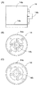
まず図1には、パチンコ機に備える遊技盤10の構成例を正面図で示す。当該遊技盤10は、図柄を含めて遊技に関する情報を表示する液晶表示器12や、各々に複数の図柄を表したリール14,20,26,32,38,44、各リールに表された図柄を見るための表示窓16,22,28,34,40,46、図柄の変動表示を実現するために各リールを個別に回転させるモータ18,24,30,36,42,48、その他に入賞装置(始動口,入賞口,大入賞口等を含む),ゲート,障害釘,風車器等を適宜に配置する。
図柄を含めた遊技に関する情報を表示する装置には、上述した液晶表示器12に代えて、7セグメントLED等のようなセグメント素子を用いた表示器,プラズマ放電を利用した表示器,LEDを縦横に配列した表示器などを用いてもよい。
[Configuration example of game board for pachinko machines]
First, in FIG. 1, the structural example of the
In the device for displaying information about games including symbols, instead of the
図示するように6つのリール14,20,26,32,38,44は、液晶表示器12の図面右側に3つのリール14,20,26を縦列させて配置し、同じく液晶表示器12の図面左側に3つのリール32,38,44を縦列させて配置する。リール14,20,26とリール32,38,44とは、液晶表示器12に近隣して配置するために向きが互いに逆になっている。この配置に合わせて、モータ18,24,30とモータ36,42,48との取り付け向きも互いに逆になっている。リール14に表された図柄は表示窓16から見ることができる。同様にしてリール20,20,26,32,38,44にそれぞれ表された図柄は、順番に表示窓22,28,34,40,46から個別に見ることができる。各モータには、正逆方向に回転可能なモータ(例えばステッピングモータ)を用いるのが望ましいが、一方向にのみ回転するモータを用いてもよい。
As shown in the figure, the six
〔リールの構造例〕
リールの構造例について、図2を参照しながら説明する。上述した6つのリール14,20,26,32,38,44は同一の構造で形成しているので、ここではリール14を代表して説明する。図2では、リール14の外観にかかる正面図を図2(A)に表し、図2(A)の図面右側から見た右側面図を図2(B)に表し、同じく図2(A)の図面左側から見た左側面図を図2(C)に表す。
[Example of reel structure]
An example of the reel structure will be described with reference to FIG. Since the six
リール14は、円筒状に形成したリール本体14aを基体として、差込部14bや段差部14c等を有する。本例のリール本体14aは、一方側端部(図2(A)では右側端部)に側板を形成し、他方側端部(図2(A)では左側端部)は開口させたままで形成する。差込部14bは上述した側板と一体に形成されており、モータの回転軸(または動力伝達機構)に接続して動力の伝達を受ける。差込部14bの形状は任意であるが、モータから動力の伝達を確実に受け得る形状、例えば円筒状の一部を直線状に切り欠いた形状(言い換えれば文字「D」と同様な断面形状)で形成するのが望ましい。段差部14cはリール本体14aの外周部に設けられ、図柄を表したフィルム(シールを含む)を当該外周部に貼付する際に位置決め機能を果たす。フィルムをリール本体14aの外周部に貼付してゆくと、フィルムが周回したうえに重なって貼付される部位が生じ、当該部位が突起する場合がある。このような突起は遊技するうえで好ましくないので、段差部14cの段差は当該フィルムの厚みとほぼ等しく形成するのが望ましい。
The
〔リールとモータの構成例〕
図1に示すように、液晶表示器12の図面右側に配置するリール14,20,26と、同じく液晶表示器12の図面左側に配置するリール32,38,44とについて、各リールをモータに接続する例について、図3を参照しながら説明する。当該図3では、リール14をモータ18に接続する例を図3(A)に示し、リール32をモータ36に接続する例を図3(B)に示す。なお、リール32はリール14と同一の構造で形成しているので、リール本体32aを基体として、差込部32bや段差部32c等を有する。
[Configuration example of reel and motor]
As shown in FIG. 1, the
図3(A)に一点鎖線で示すように、モータ18の回転軸18aをリール14の差込部14bに差し込む。この差し込みにより、回転軸18aの回転に伴ってリール14が所定方向(本例では矢印D2で示す方向)に回転するようになる。リール14の開口部分からは、筒内にバックライト14dを入れた状態で固定し、リール14に表された図柄を照らし出す。当該バックライト14dの数は任意であって、一個でもよく複数個でもよい。発光色の数もまた任意であって、単色(例えば豆電球のような白色等)で発光させてもよく、複数色(例えば赤色,青色,黄色,白色等)で切り換えて発光させてもよい。
また図3(B)に一点鎖線で示すように、モータ36の回転軸36aをリール32の差込部32bに差し込む。この差し込みにより、回転軸36aの回転に伴ってリール32が上記リール14とは逆方向(本例では矢印D4で示す方向)に回転するようになる。リール32の開口部分からは、筒内にバックライト32dを入れた状態で固定する。当該バックライト32dによって、後方側からリール32に表された図柄を照らし出す。なお、各リールに表された図柄を照らし出す点では、バックライト14d,32d,…は照明手段に相当する。
As shown by the alternate long and short dash line in FIG. 3A, the rotating
3B, the
リール20,26についてそれぞれモータ24,30に接続する例はリール14をモータ18に接続する例と同様であり、リール38,44についてそれぞれモータ42,48に接続する例はリール32をモータ36に接続する例と同様であるので、これらの図示および説明を省略する。モータ18,24,30,36,42,48を駆動制御してリール14,20,26,32,38,44を回転させ、表示窓16,22,28,34,40,46を通じて図柄の変動表示を実現する点では、機械式表示器に相当する。
The example of connecting the
〔フィルムの構成例〕
リール14,20,26,32,38,44にそれぞれ貼付するフィルムの一例について、図4を参照しながら説明する。当該図4に示すフィルム50には、いずれもが数字図柄「7」を認識できる4つの図柄50a,50b,50c,50dが表されている。これらの図柄は色が互いに異なり、図柄の色や配列等は任意に設定できる。例えば、図柄50aは赤色(縦線ハッチで図示する)、図柄50bは青色(横線ハッチで図示する)、図柄50cは黄色(斜線ハッチで図示する)、図柄50dは白色(輪郭線のみで図示する)で設定する。液晶表示器12で表示する図柄もまた、フィルム50に表す図柄と同一にするか、遊技者が同一の図柄と認識できる図柄(例えば漢数字の「七」等)にする。
なお、図柄50dの白色部分(輪郭線で囲まれた部位)は、他の図柄と比べてバックライトの透過率が高くなるように施す。こうすることにより、図柄50dはバックライトで表す色がそのまま図柄の色となる。
[Example of film structure]
An example of the film affixed to each of the
In addition, the white part (part surrounded by the outline) of the
〔制御基板の接続例〕
複数の制御基板を電気的に接続する例について、図5を参照しながら説明する。当該図5において、パチンコ機には払出制御基板52,メイン制御基板56,枠装飾分配基板58,サブ制御基板62,図柄制御基板70などを備える。
[Control board connection example]
An example of electrically connecting a plurality of control boards will be described with reference to FIG. In FIG. 5, the pachinko machine includes a
払出制御基板52は、メイン制御基板56からコネクタ54を通じて伝達される払出用信号に従い、球払出装置を通じてパチンコ球を払い出す制御を行う。
CPU(プロセッサ)56aを中心に構成したメイン制御基板56は、パチンコ機における遊技の進行を制御する。当該制御にあたって、遊技制御プログラムや一定のデータ等を格納するROM56bや、乱数や保留数等のような一時的データを記憶するRAM56c、図示しないが入出力処理回路や通信制御回路などを備える。
The
A
サブ制御基板62はメイン制御基板56と同様にCPUを中心に構成され、当該メイン制御基板56から伝達される遊技用信号を受けて周辺機器を制御する。すなわちサブ制御基板62は、図柄制御基板70を介して液晶表示器12に行う表示を制御したり、コネクタ60を通じてスピーカ68から出す音を制御したり、同じくコネクタ60を通じて枠装飾分配基板58に装飾用信号を出力する制御などを行う。
Similar to the
図柄制御基板70もまたメイン制御基板56と同様にCPUを中心に構成され、遊技用信号を表示用信号に変換して液晶表示器12に伝達する制御や、モータ18,24,30,36,42,48の作動(回転や停止等)にかかる制御などを行う。図柄制御基板70には、後述する変動表示処理や演出制御処理等の手続きを実現するプログラムを含む記憶手段(例えばROM等)を備える。
枠装飾分配基板58は、サブ制御基板62から伝達される装飾用信号を受けてスピーカ64から出す音や、発光体66(ランプやLED等)の点灯/点滅などを制御する。
Similarly to the
The frame
〔液晶表示器およびリールによる図柄の変動表示〕
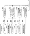
上述のように構成したパチンコ機において、液晶表示器12およびリール14,20,26,32,38,44を用いて図柄の変動表示を行う例を説明する。図6に示す変動表示処理および図7に示す演出制御処理は、いずれも上述した図柄制御基板70(またはサブ制御基板62)において実現される。図柄の変動表示は、抽選表示用図柄を用いる変動表示であってもよく、装飾用図柄を用いて演出する変動表示であってもよい。
装飾用図柄を用いる変動表示では、パチンコ機の内部状態と異なる表示を行う場合がある。例えば内部状態としてリーチを取り得ない場合であっても、当該リーチにかかる演出(すなわち見かけ上のリーチ)を表示することもある。
[Variable display of design by liquid crystal display and reel]
In the pachinko machine configured as described above, an example will be described in which a variable display of symbols is performed using the
In the variable display using the decorative design, a display different from the internal state of the pachinko machine may be performed. For example, even when reach cannot be taken as an internal state, an effect related to the reach (that is, apparent reach) may be displayed.
図6に示す変動表示処理では、メイン制御基板56から表示用信号(表示用コマンドを含む)を受信し(ステップS10でYES)、かつ当該表示用信号によって変動表示を行う場合には(ステップS12でYES)、次のように処理する。すなわち、図柄制御基板70が選択した変動表示パターンに従って図柄の変動表示を始め〔ステップS14〕、当該変動表示の一部にかかる演出を実現する演出制御処理を実行し〔ステップS16〕、変動表示を行う変動期間を経過すると今回の抽選にかかる変動表示を終えて停止表示用図柄を表示したうえで〔ステップS18〕、変動表示処理を終える。ステップS16の演出制御処理の具体的な手続きについては、次に説明する。
In the variation display process shown in FIG. 6, when a display signal (including a display command) is received from the main control board 56 (YES in step S10) and the variation display is performed by the display signal (step S12). YES), processing is as follows. That is, according to the variation display pattern selected by the
図7に示す演出制御処理は、液晶表示器12およびリール14,20,26,32,38,44を用いて演出を実現する一例である。説明を簡単にするため、液晶表示器12およびリール14,20,26,32,38,44の双方を用いて演出を行うことを前提とし、当該リール14,20,26,32,38,44を停止させるタイミングを中心に説明する。本例におけるリール14,20,26,32,38,44の停止は、所定の順番(またはランダムの順番)に従って停止させる場合と、一斉に停止させる場合とがある。リール14,20,26,32,38,44によるリーチ表示は、内部状態としてのリーチではなく、見かけ上のリーチであるが便宜上「リーチ表示」と呼ぶことにする。
The effect control process shown in FIG. 7 is an example of realizing an effect using the
まず現在の遊技状態が時短中でなく通常状態であれば(ステップS20でNO)、一の時短中に行う変動表示の回数(以下では単に「時短変動回数」と呼ぶ。)を所定値でクリアする〔ステップS32〕。通常では所定値をゼロに設定するが、遊技状態等に応じて他の数値(例えば1や2等)に設定してもよい。前回の抽選で時短を伴う大当たりであれば、終了条件を満たすまでは時短中(他には「時短モード」とも呼ぶ。)に入る。当該終了条件は任意に設定可能であるが、例えば時短中に入ってから所定回数(20回等)の変動表示を行うことや、所定期間(例えば15分間)を経過すること等が該当する。
なおステップS32では、後述するようにステップS30の実行により液晶表示器12のみで表示する形態となっている場合には、液晶表示器12とリール14,20,26,32,38,44とで図柄を表示する標準の表示形態に戻す。
First, if the current gaming state is not a short time but a normal state (NO in step S20), the number of variable displays performed during one short time (hereinafter simply referred to as “short time variation number”) is cleared with a predetermined value. [Step S32]. Normally, the predetermined value is set to zero, but may be set to other numerical values (for example, 1 or 2) according to the gaming state or the like. If the previous lottery is a big hit with a short time, the time is short (otherwise referred to as “short time mode”) until the end condition is satisfied. The termination condition can be arbitrarily set. For example, it is possible to display a variable display a predetermined number of times (20 times, etc.) after a short time, or to pass a predetermined period (for example, 15 minutes).
In step S32, when the display is performed only on the
もし現在の遊技状態が時短中であれば(ステップS20でYES)、時短変動回数を増やしたうえで〔ステップS22〕、次のようにしてリール14,20,26,32,38,44の回転を停止する制御を行う。すなわち、変動表示の途中でリーチ表示を行う場合や(ステップS24でYES)、大当たり表示を行う場合は(ステップS26でYES)、通常通りの変動表示を行うために、液晶表示器12とともにリール14,20,26,32,38,44の回転・停止の制御もまた通常通りに行う。
If the current gaming state is short (YES at step S20), the number of time fluctuations is increased [step S22], and the
大当たり表示を行う場合については(ステップS26でYES)、一以上のリールを回転させる制御を行う構成としてもよい〔ステップS34〕。例えば、液晶表示器12で大当たり表示になるまではリール14,20,26,32,38,44を停止させたままにする。そして、液晶表示器12で大当たり表示を行う以後は、当該大当たり表示に合わせて一以上のリールを回転させるとともにバックライト14d,32d,…を点灯する。これにより、液晶表示器12とリール14,20,26,32,38,44とで大当たり表示が行われるので、遊技者は大当たり(当選)を認識し易くなる。
When the jackpot display is performed (YES in step S26), it may be configured to perform control for rotating one or more reels [step S34]. For example, the
これに対してリーチに達するまでもなくハズレとなる変動表示パターンであって、かつ時短に入ってから1回目の変動表示では(ステップS28でYES)、変動表示とは無関係にリール14,20,26,32,38,44を一時的に動かした後にバックライト14d,32d,…を消灯する〔ステップS36〕。
上述した「一時的に動かす」とは、リーチにもならない状態となるように一以上のリールを回転させ、その後に停止させる形態である。当該形態において、リール14,20,26,32,38,44によって表示される図柄がリーチにならない状態にするための回転角であればよいので、多くは360度(1回転)未満の回転角で済む。このときの回転速度は任意に設定してもよいが、遊技者が変動表示とは無関係の回転であることを認識できるようにするため、他の変動表示よりもゆっくり回転させるのが望ましい。バックライト14d,32d,…を消灯するのは、当該消灯にかかるリールに表示された図柄が演出表示とは無関係である点を明らかにして遊技者に知らせることを目的とする。
On the other hand, it is a fluctuation display pattern that loses before reaching reach, and in the first fluctuation display after entering the short time (YES in step S28), the
The “moving temporarily” described above is a form in which one or more reels are rotated so as not to reach, and then stopped. In this embodiment, since the rotation angle for preventing the symbols displayed by the
リーチに達するまでもなくハズレとなる変動表示パターンであって、かつ時短に入ってから2回目以降の変動表示では(ステップS28でNO)、上述したようにリール14,20,26,32,38,44による図柄の表示はリーチにならない状態で停止している〔ステップS36〕。そのため、次回以降の変動表示に備えて液晶表示器12のみで変動表示を行い、リーチ表示や大当たり表示が可能となるように表示形態を切り替えたうえで〔ステップS30〕、リール14,20,26,32,38,44の停止および消灯の状態を維持する〔ステップS38〕。
As described above, the
〔複合表示器による演出例〕
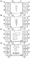
上述した変動表示処理,演出制御処理等を実行し、液晶表示器12とリール14,20,26,32,38,44とからなる複合表示器を用いた演出の一例について図8〜図10を参照しながら説明する。これらの図のうちで、図8には通常の変動表示を行う例を示し、図9,図10にはそれぞれ時短中における特定の変動表示を行う例を示す。
ここで、図8〜図10に示す液晶表示器12の画面上には、装飾用図柄を用いて変動表示を模擬する装飾表示領域12aと、抽選用図柄にかかる普通図柄を表示する普通図柄領域12bと、抽選用図柄にかかる特別図柄を表示する特別図柄領域12cとを有する。特別図柄の内容は任意に設定できるが、本例では円形「○」,三角形「△」,十字形「+」,ハート形状をそれぞれ表した図柄を用いる。大当たり表示は、例えば特別図柄について同じ形状の図柄が二つ表示されたことと仮定する。普通図柄領域12bでは普通図柄の変動表示を開始する条件を満たすと(例えばパチンコ球がゲートを通過すると)、変動表示を始めて、その後に停止表示する。以下では、特別図柄の変動表示について説明する。
[Example of production using a composite display]
FIG. 8 to FIG. 10 show examples of effects using the composite display composed of the
Here, on the screen of the
〔第1演出例〕
まず第1演出例は、大当たり遊技を終えた後に行われる時短を除く通常の変動表示や、当該時短中におけるリーチ表示または大当たり表示を含む変動表示に適用する例である。本例では、大当たり表示を含む変動表示について説明する。
[First production example]
First, the first effect example is an example applied to a normal variable display excluding a short time performed after the jackpot game is finished, and a variable display including a reach display or a jackpot display during the short time. In this example, variable display including jackpot display will be described.
図8において、特別図柄の変動表示を開始する条件を満たすと(例えばパチンコ球が始動口に入賞すると)、メイン制御基板56は抽選を行うとともに、サブ制御基板62に表示用信号を伝達する。当該表示用信号を受けたサブ制御基板62は、図8(A)に示すように液晶表示器12および表示窓16,22,28,34,40,46で変動表示を始める(図6のステップS14)。液晶表示器12では、装飾表示領域12aにおける模擬的な変動表示と、特別図柄領域12cにおける変動表示とを並行して行う。表示窓16,22,28,34,40,46では、リール14,20,26,32,38,44をそれぞれ回転させることにより変動表示を実現する。
In FIG. 8, when the condition for starting the variable symbol display is satisfied (for example, when the pachinko ball wins the start opening), the
変動表示の途中には、次のような演出表示を行う(図7のステップS26)。すなわち図8(B)に示すように、一部の表示窓についてはリールを停止することにより変動表示を停止し、図柄を表示する。本例では、表示窓22,28,34,40についてそれぞれ白色の図柄「7」を表示している。言い換えれば、白色の図柄「7」を表示しているリールのバックライトを白色で点灯している。
さらに表示窓16,46について変動表示を停止し、装飾表示領域12aにおける模擬的な変動表示を停止すると、図8(C)のようになる。本例では表示窓16,22,28,34,40,46では白色の図柄「7」が表示されているが、装飾表示領域12aには赤色の図柄「7」が表示されている。現時点では、上段横,中段横,下段横,斜めの各一列上に同色の図柄「7」が揃っていない。そのため、遊技者は今回の抽選がハズレ(落選)であったと思う可能性が高い。
In the middle of the variable display, the following effect display is performed (step S26 in FIG. 7). That is, as shown in FIG. 8B, for some display windows, the variable display is stopped by stopping the reels, and the symbols are displayed. In this example, a white symbol “7” is displayed for each of the
Further, when the variable display is stopped for the
図8(C)の表示を行なった後は、全てのリール14,20,26,32,38,44にかかるバックライト14d,32d,…の発光色を切り換えてゆく演出を行い、最終的には赤色で点灯するように制御する。こうすれば図8(D)に示すように、液晶表示器12および表示窓16,22,28,34,40,46で表示される図柄が全て赤色の図柄「7」となり、上段横,中段横,下段横,斜めの各一列上に同色の図柄「7」が揃うことになる。バックライト14d,32d,…の赤色点灯とほぼ同時に特別図柄領域12cにおける変動表示を停止し、円形「○」の図柄が二つ表示される(図6のステップS18)。上述した表示により大当たり表示を実現し、大当たり遊技を行う。大当たり表示を見た遊技者は、今回の抽選が大当たり(当選)であることを知る。
なお、大当たり遊技は遊技者に有利な遊技状態であって、例えば所定数のラウンドを上限とし、各ラウンドでは所定の制限下で大入賞口を開放する遊技が該当する。具体的な構成や作動等は周知の技術を採用すれば実現できるので、図示および説明を省略する。
After the display of FIG. 8 (C) is performed, an effect of switching the light emission colors of the
Note that the jackpot game is a game state advantageous to the player, for example, a game in which a predetermined number of rounds is set as an upper limit, and a big winning opening is opened under a predetermined limit in each round. Since a specific configuration, operation, and the like can be realized by using a well-known technique, illustration and description are omitted.
〔第2演出例〕
第2演出例は、時短を始めてから1回目の変動表示に適用する例である。本例では、ハズレ表示を含む変動表示について説明する。以下では、図8に示す変動表示によって大当たりになり、かつ大当たり遊技後に時短を行うことを前提として説明する。当該大当たり遊技中は、リール14,20,26,32,38,44を停止させたままと仮定する。
[Second production example]
The second effect example is an example applied to the first variable display after the start of time reduction. In this example, a variable display including a loss display will be described. The following description is based on the premise that the change display shown in FIG. 8 is a big hit and the time is shortened after the big win game. It is assumed that the
まず、表示窓16,22,28,34,40,46について、変動表示を始める直前の状態は図8(D)に示す通りである。時短を始めてから1回目の変動表示では、液晶表示器12では変動表示を行うが、表示窓16,22,28,34,40,46では変動表示を行わない。よって、液晶表示器12における変動表示を始めるとともに(図6のステップS14)、表示窓16,22,28,34,40,46に表示する図柄についてリーチにならない状態とするための準備を行う(図7のステップS36)。
First, the state of the
例えば図9(A)に示すように、表示窓22,34,46に表示する図柄を変更するためにリール20,32,44をゆっくりと回転させる(矢印付きの破線で図示する)。言い換えれば、上段横,中段横,下段横,斜めの各一列上に同色の図柄「7」が揃わないようにリール20,32,44をゆっくりと回転させて停止する。こうして停止させた後の状態を図9(B)に示す。本例では、表示窓22,46にそれぞれ黄色の図柄「7」を表示し、表示窓34に青色の図柄「7」を表示する。こうしてリール14,20,26,32,38,44に表示される図柄の組み合わせは、見かけ上のリーチとなり得ない。
リール20,32,44を停止させた後には、さらに全てのリール14,20,26,32,38,44にかかるバックライト14d,32d,…を消灯する。図9(B)に示す例では消灯状態をグレーの網掛けで図示しており、図9(C),図9(D),図10(A),図10(B),図10(C)についても同様である。このようにバックライトを消灯することにより、遊技者は各表示窓に表示される図柄を認識することは可能であるものの、変動表示や演出表示とは無関係な表示であると理解し易い。
For example, as shown in FIG. 9A, the
After the
液晶表示器12における変動表示は、第1演出例と同様にして、装飾表示領域12aにおける模擬的な変動表示と、特別図柄領域12cにおける変動表示とを並行して行う。上述した第1演出例では一のみの変動表示を行うのに対して、本演出例では複数の変動表示を行う点で異なる。図9(A),図9(B)に示す例では、装飾表示領域12a内で上段,中段,下段についてそれぞれ変動表示を行なっている。
The variation display on the
その後は、装飾表示領域12aにおける各段の変動表示を順次停止させ、上段および下段について停止させた状態を図9(C)に示す。当該図9(C)に示す例では、上段に黄色の図柄「7」が表示され、下段に赤色の図柄「7」が表示されている。最終的には、装飾表示領域12aにおける中段の変動表示を停止させるとともに、特別図柄領域12cにおける変動表示も停止させる(図6のステップS18)。こうして全ての変動表示を停止した表示状態を図9(D)に示す。当該図9(D)に示す例では、中段に青色の図柄「7」が表示され、特別図柄領域12cには円形「○」の図柄と十字形「+」の図柄とが表示されている。装飾表示領域12aにおける上段,中段,下段に表示された図柄の列は、同色の図柄「7」とはなっておらず、特別図柄領域12cに表示された二つの図柄は一致していない。上述した表示によりハズレ表示を実現し、これらを見た遊技者は今回の抽選がハズレ(落選)であることを知る。
なお消灯したリールに表示された図柄との関係についても、上段横,中段横,下段横,斜めの各一列上には同色の図柄「7」が揃っていない。したがって、遊技者が大当たりになったと勘違いするのを防止できる。
Thereafter, FIG. 9C shows a state in which the variable display of each stage in the
Regarding the relationship with the symbols displayed on the unlit reels, the same-color symbol “7” is not arranged on each of the upper row, middle row, lower row, and diagonal rows. Therefore, it is possible to prevent the player from misunderstanding that the player has won the jackpot.
〔第3演出例〕
第3演出例は、時短を始めてから2回目以降に行う変動表示に適用する例である。本例では、大当たり表示を含む変動表示について説明する。大当たり表示を含む変動表示は第1演出例を適用してもよいが、意外性を醸し出すために本演出例を適用してもよい。
[Third production example]
The third effect example is an example applied to variable display that is performed for the second and subsequent times after the start of time reduction. In this example, variable display including jackpot display will be described. Although the first display example may be applied to the variable display including the jackpot display, the present display example may be applied in order to bring out unexpectedness.
時短を始めてから1回目の変動表示時には、表示窓16,22,28,34,40,46に表示する図柄についてリーチにならない状態とするために一以上のリールを一時的に動かしているので(第2演出例;図7のステップS36)、その状態を維持する。したがって、変動表示を開始したときの表示状態は図10(A)のようになり、上述した図9(B)の表示状態と同じである。
Since the one or more reels are temporarily moved so that the symbols displayed on the
液晶表示器12では、第2演出例と同様にして装飾表示領域12aにおける模擬的な変動表示と、特別図柄領域12cにおける変動表示とを並行して行う。その後、装飾表示領域12aにおける各段の変動表示を順次停止させ、上段および下段について停止させた状態を図10(B)に示す。当該図10(B)に示す例では、上段および下段にそれぞれ黄色の図柄「7」が表示されているので、リーチ表示を実現している。最終的には、装飾表示領域12aにおける中段の変動表示を停止させるとともに、特別図柄領域12cにおける変動表示も停止させる(図6のステップS18)。
In the
こうして全ての変動表示を停止した表示状態を図10(C)に示す。当該図10(C)に示す例では、中段にも黄色の図柄「7」が表示され、特別図柄領域12cには三角形「△」の図柄が二つ表示されている。装飾表示領域12aにおける上段,中段,下段に表示された図柄の列は同色の図柄「7」で一致し、特別図柄領域12cに表示された二つの図柄もまた一致する。そして図10(D)に示すように、液晶表示器12には大きな黄色の図柄「7」を表示するとともに、表示窓16,22,28,34,40,46に表示する図柄が全て黄色の図柄「7」となるように一以上のリールを一時的に回転させ、全てのバックライト14d,32d,…を点灯する(図7のステップS34)。この作動制御により、液晶表示器12および表示窓16,22,28,34,40,46の全てで黄色の図柄「7」が表示され、上段横,中段横,下段横,斜めの各一列上に同色の図柄「7」が揃う。上述した表示により大当たり表示を実現し、大当たり遊技を行う。大当たり表示を見た遊技者は、今回の抽選が大当たり(当選)であることを容易に知る。このような表示形態は、見かけ上のハズレ表示や通常の大当たり表示などから、確率変動を伴う見かけ上の大当たり表示を行う場合に有効である。
A display state in which all the variable displays are stopped in this way is shown in FIG. In the example shown in FIG. 10C, a yellow symbol “7” is also displayed in the middle stage, and two triangles “Δ” are displayed in the
上述した実施例によれば、以下に示す各効果を得ることができる。
(1)大当たり遊技後の時短中における1回目の変動表示では(すなわち所定の動作条件を満たすことを契機として)、液晶表示器12に表示される図柄との組み合わせがリーチにならない状態(すなわち所定の図柄の組み合わせとはなり得ない図柄を表示した状態)でリール14,20,26,32,38,44の動作を停止させた{動作制御手段;図7のステップS36を参照}。よってリール14,20,26,32,38,44に表示される図柄のみでは見かけ上のリーチにもなり得ないので、液晶表示器12のみを動作させて図柄を表示した場合でも、見かけ上のリーチ表示や大当たり表示になることもない。したがって、リール14,20,26,32,38,44に表示される図柄が認識できる場合においても、実際には大当たりになっていないのに遊技者等が大当たりになったと誤認するのを防止できる。また、別個に液晶シャッターやハーフミラー等の部材を必要としないので、従来のパチンコ機と同様にコストを低く抑えることができ、リール14,20,26,32,38,44に表示される図柄も従来通りの視認性を確保できる。
According to the embodiment described above, the following effects can be obtained.
(1) In the first variable display after the jackpot game (ie, triggered by satisfying a predetermined operation condition), the combination with the symbols displayed on the
なお上述した実施例では、所定の動作条件として「大当たり遊技後の時短中における1回目の変動表示であること」を適用したが、他の動作条件を設定してもよい。例えば、時短中であることや、所定回数目(1回目,5回目等)の変動表示であること、リールの動作を行うか否かの抽選を行なって所定の結果となったこと等が該当する。遊技状態が変化してゆくにつれて条件を変えれば、遊技者は当該条件を満たそうと遊技するので、パチンコ遊技が面白くなる。 In the above-described embodiment, “the first variable display during the short time after the big hit game” is applied as the predetermined operation condition. However, other operation conditions may be set. For example, it means that the time is short, it is a variable display for a predetermined number of times (first time, fifth time, etc.), or a lottery is performed to determine whether or not to operate the reel, and a predetermined result is obtained. To do. If the condition is changed as the gaming state changes, the player plays to satisfy the condition, so the pachinko game becomes interesting.
(2)大当たり遊技後の時短中における2回目以降の変動表示では(すなわち所定の切替条件を満たすことを契機として)、液晶表示器12のみで変動表示を行うように表示形態を切り替えた{表示切替手段;図7のステップS30,図9,図10を参照}。すなわち、リーチ表示や大当たり表示が可能となる数の図柄を液晶表示器12に表示する。よって遊技者等が誤認するのを防止しながらも、液晶表示器12のみでリーチ表示や大当たり表示を行い、大当たり遊技を実現できるようになる。
(2) In the second and subsequent variable display after the jackpot game (that is, triggered by satisfying a predetermined switching condition), the display form is switched so that the variable display is performed only on the liquid crystal display 12 {Display Switching means; see step S30 in FIG. 7, FIG. 9, FIG. In other words, the
(3)複数の可変表示体として、6つのリール14,20,26,32,38,44を備えた{図1,図8〜図10を参照}。リール14,20,26,32,38,44にそれぞれ表示される図柄の組み合わせが見かけ上のリーチとならない状態(所定の図柄の組み合わせの一部を構成しない状態)で当該リール動作を停止させた{動作制御手段;図7のステップS36を参照}。特に図9(D)に示す表示例から明らかなように、消灯により変動表示とは無関係とした場合でもリール14,20,26,32,38,44に表示される図柄は表示窓16,22,28,34,40,46を通じて認識することができる。しかし、この場合でも見かけ上のリーチとならない状態で図柄が表示されるので、液晶表示器12に表示された図柄とを組み合わせても、遊技者等が大当たりになったと誤認することはない。したがって、遊技者等の誤認を確実に防止できる。
(3) Six
(4)リール14,20,26,32,38,44に向けて照らすバックライト14d,32d,…14d,32d,…を備えた{図3を参照}。この構成において、リール14,20,26,32,38,44の動作を停止させるとともに、バックライト14d,32d,…を消灯するように制御した{動作制御手段;図7のステップS36を参照}。このようにバックライト14d,32d,…を消灯していれば、例え図柄を視認できたとしても見かけ上のリーチ表示や大当たり表示の対象とはならないことを明示することができる。そのため、遊技者等が大当たりになったと誤認するのをより確実に防止できる。
なお、本例では照明手段としてバックライト14d,32d,…を適用したが、図柄を照らし出すことが可能な他の照明手段を用いてもよい。例えば前方側から照らすフロントライトや、横側,上側,下側等から照らすサイドライト等が該当する。
(4)
In this example, the
〔他の実施例〕
以上、本発明を実施するための最良の形態について実施例に従って説明したが、本発明は当該実施例に何ら限定されるものではない。言い換えれば、本発明の要旨を逸脱しない範囲内において、種々なる形態で実施することが可能である。例えば、次に示す各形態を実現してもよい。
[Other Examples]
As mentioned above, although the best form for implementing this invention was demonstrated according to the Example, this invention is not limited to the said Example at all. In other words, the present invention can be implemented in various forms without departing from the gist of the present invention. For example, the following forms may be realized.
(1)上述した実施例では、パチンコ機に本発明を適用した。この形態に代えて、パチンコ機以外の他の遊技機(例えばスロットマシン,アレンジボール機,雀球遊技機,テレビゲーム機等)であって、機械式表示器と電気式表示器との双方を備えたものにも同様に本発明を適用することができる。例えばスロットマシンでは、リール14,20,26,32,38,44に類似する回転体を有するので、液晶表示器12と同等の電気式表示器を備えたものが対象となり得る。当該他の遊技機であっても、電気式表示器に表示される図柄との組み合わせが所定の図柄の組み合わせとはなり得ない図柄となるように機械式表示器の動作を停止する制御を行えばよい{図7の演出制御処理を参照}。こうすればコストを低く抑えるとともに図柄の視認性を確保したうえで、電気式表示器のみを動作させて図柄を表示した場合でも遊技者等が大当たりになったと誤認するのを防止できる。
(1) In the embodiment described above, the present invention is applied to a pachinko machine. Instead of this form, it is a gaming machine other than a pachinko machine (for example, a slot machine, an arrangement ball machine, a sparrow ball game machine, a video game machine, etc.), which has both a mechanical display and an electric display. The present invention can be similarly applied to those provided. For example, the slot machine has a rotating body similar to the
(2)上述した実施例では、図柄を視認可能な形態でリール14,20,26,32,38,44の動作を制御した{図7の演出制御処理を参照}。この形態に代えて(あるいは加えて)、図柄を視認不能な形態でリール14,20,26,32,38,44の動作を制御するように制御してもよい。当該制御は、一定条件(例えば時短中や所定回数目の変動表示等)を満たすことを契機として行うように構成してもよく、無条件で行うように構成してもよい。「図柄を視認不能な形態」としては、リール14,20,26,32,38,44に表された図柄を肉眼で識別し難い形態であればよい。例えば、リールの回転速度を高速にして表示する形態や、リールの回転方向を交互に切り換えて動かすことで図柄が上下に絶えずに動いているような揺動変動を実現する形態などが該当する。こうすればリール14,20,26,32,38,44を見たときには定位置で図柄を視認不能になるので、液晶表示器12に表示される図柄との組み合わせが見かけ上のリーチ表示や大当たり表示等になることはない。したがって、液晶表示器12のみを動作させて図柄を表示した場合でも、遊技者等は大当たりになったと誤認せず、コストも低く抑えられる。
(2) In the above-described embodiment, the operations of the
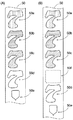
(3)上述した実施例では、リール14,20,26,32,38,44で表す図柄は見かけ上のリーチ表示や大当たり表示等が可能な図柄のみで構成した{図4を参照}。この形態に代えて、見かけ上のリーチ表示や大当たり表示等にならない図柄(すなわち所定の図柄の組み合わせを構成しない図柄)を、リール14,20,26,32,38,44のうちで一以上のリールに表す構成としてもよい。例えば図11(A)に示すように、図柄50dと図柄50aとの間に図柄50eを表したフィルム50を各リールに貼付する。図柄50eは、エンブレムを模した形状からなる。また図11(B)に示するように、図柄50eとは異なる他の図柄50fを表したフィルム50を各リールに貼付する。図柄50fは形状のない無地(例えば白色)からなり、分かり易くするために破線で表している。図柄50e,50fはいずれも見かけ上のリーチ表示や大当たり表示等を構成しない図柄であって、所定の図柄の組み合わせに相当する。当該図柄50e,50fが表示窓16,22,28,34,40,46の全部または一部に表示されるようにリール14,20,26,32,38,44の回転を制御すれば、遊技者等が大当たりになったと誤認するのをより確実に防止できる。
なお本例では、所定の図柄の組み合わせに該当しない図柄として図柄50e,50fを適用したが、背景として用いる図柄を適用してもよい。また一のみの図柄50e,50fをフィルム50に表したが、二以上をフィルム50に表してもよい。これらの場合であっても、遊技者等が大当たりになったと誤認するのをより確実に防止できる。
(3) In the above-described embodiment, the symbols represented by the
In this example, the
(4)上述した実施例では、特別図柄領域12cの表示とともに、装飾表示領域12aおよび表示窓16,22,28,34,40,46について上段横,中段横,下段横,斜めの各一列上に同色の図柄「7」が揃う表示を行うことにより、大当たり表示を実現した{図8(D),図10(D)を参照}。これらの上段横,中段横,下段横,斜めの各一列は「有効ライン」と呼ばれる。当該有効ライン上に同色の図柄「7」が揃って表示されると、見かけ上の大当たり表示となって、遊技者は大当たりになったと認識する。これを逆に考えれば、有効ライン上に同色の図柄「7」が揃って表示されないときは、見かけ上のハズレ表示となる。そこで、有効ラインから外れた位置に図柄を表示した状態でリール14,20,26,32,38,44の動作を停止させるように制御してもよい{動作制御手段;図6のステップS36を参照}。この制御による表示例を図12に示す。当該図12では、各表示窓16,22,28,34,40,46に、斜線ハッチとともに「7」の下半分を図示する黄色の図柄50cと、輪郭線のみで「7」の上半分を図示する白色の図柄50dとが表示されている。また分かり易くするために、図12では有効ラインを破線で表している。このように有効ラインから外れた位置(本例では図柄相互間のほぼ中間位置)に図柄を表示した状態でリール14,20,26,32,38,44を停止させると、見かけ上のリーチ表示や大当たり表示の対象とはならないことが明らかになる。したがって、遊技者等が大当たりになったと誤認するのをより確実に防止できる。
(4) In the embodiment described above, in addition to the display of the
(5)上述した実施例では、液晶表示器12の図面右側に3つのリール14,20,26を縦列させて配置し、同じく液晶表示器12の図面左側に3つのリール32,38,44を縦列させて配置する構成とした{図1,図8〜図10を参照}。この形態に代えて、液晶表示器12の図面左右両側にそれぞれ配置するリールの数を1つとしてもよく、5つとしてもよい。液晶表示器12の図面右側にリール14(表示窓16)を配置し、液晶表示器12の図面左側にリール32(表示窓34)を配置した例を図13〜図15に示す。液晶表示器12およびリール14,32に表示する例は、図13が図8の表示例に対応し、図14が図9の表示例に対応し、図15が図10の表示例に対応する。これらの表示でも表示窓16,34に表示される図柄のみでは見かけ上のリーチにもならないので、液晶表示器12のみを動作させて図柄を表示した場合でも、見かけ上のリーチ表示や大当たり表示になることもない。したがって、上述した実施例とリールの数を異ならせた場合でも、実施例と同様の効果を得ることができる。
(5) In the embodiment described above, the three
(6)上述した実施例では、特別図柄の変動表示について本発明を適用したが、普通図柄の変動表示についても同様に本発明を適用してもよい。液晶表示器12およびリール14,20,26,32,38,44の動作を制御するのは、図柄制御基板70が選択した変動表示パターンに従ったがメイン制御基板56によって指定された変動表示パターンに従ってもよい。見かけ上のリール表示および大当たり表示について本発明を適用したが、内部状態に基づくリール表示および大当たり表示について本発明を適用してもよい。いずれの形態にせよ、遊技者等が大当たりになったと誤認するのを防止できる。
(6) In the above-described embodiments, the present invention is applied to the special symbol variation display. However, the present invention may also be applied to the normal symbol variation display. The operation of the
10 遊技盤
12 液晶表示器(電気式表示器)
14,20,26,32,38,44 リール(機械式表示器)
14a,32a,… リール本体
14b,32b,… 差込部
14c,32c,… 段差部
14d,32d,… バックライト
16,22,28,34,40,46 表示窓
18,24,30,36,42,48 モータ(機械式表示器)
18a,36a,… 回転軸
50 フィルム
50a,50b,50c,50d,50e,50f 図柄
52 払出制御基板
54 コネクタ
56 メイン制御基板
56b ROM
56c RAM
58 枠装飾分配基板
60 コネクタ
62 サブ制御基板
64,68 スピーカ
66 発光体
70 図柄制御基板
10
14, 20, 26, 32, 38, 44 Reel (Mechanical display)
14a, 32a, ...
18a, 36a,... Rotating
56c RAM
58 Frame
Claims (1)
所定の動作条件を満たすことを契機として、前記機械式表示器の動作を停止させる動作制御手段を有する遊技機。
It is equipped with a mechanical display and electrical display that can display symbols, and is configured to realize a jackpot game when a combination of these mechanical displays and electrical displays displays a predetermined combination of symbols. A gaming machine,
A gaming machine having operation control means for stopping the operation of the mechanical display when a predetermined operation condition is satisfied.
Priority Applications (1)
| Application Number | Priority Date | Filing Date | Title |
|---|---|---|---|
| JP2004033461A JP2005224286A (en) | 2004-02-10 | 2004-02-10 | Game machine |
Applications Claiming Priority (1)
| Application Number | Priority Date | Filing Date | Title |
|---|---|---|---|
| JP2004033461A JP2005224286A (en) | 2004-02-10 | 2004-02-10 | Game machine |
Related Child Applications (1)
| Application Number | Title | Priority Date | Filing Date |
|---|---|---|---|
| JP2010057340A Division JP5183657B2 (en) | 2010-03-15 | 2010-03-15 | Game machine |
Publications (2)
| Publication Number | Publication Date |
|---|---|
| JP2005224286A true JP2005224286A (en) | 2005-08-25 |
| JP2005224286A5 JP2005224286A5 (en) | 2009-07-16 |
Family
ID=34999462
Family Applications (1)
| Application Number | Title | Priority Date | Filing Date |
|---|---|---|---|
| JP2004033461A Pending JP2005224286A (en) | 2004-02-10 | 2004-02-10 | Game machine |
Country Status (1)
| Country | Link |
|---|---|
| JP (1) | JP2005224286A (en) |
Cited By (5)
| Publication number | Priority date | Publication date | Assignee | Title |
|---|---|---|---|---|
| JP2016140580A (en) * | 2015-02-02 | 2016-08-08 | 株式会社ニューギン | Game machine |
| JP2016140581A (en) * | 2015-02-02 | 2016-08-08 | 株式会社ニューギン | Game machine |
| JP2016140579A (en) * | 2015-02-02 | 2016-08-08 | 株式会社ニューギン | Game machine |
| US9564021B2 (en) | 2012-06-06 | 2017-02-07 | Aristocrat Technologies Australia Pty Limited | Gaming system and a method of gaming |
| US9886822B2 (en) | 2012-07-03 | 2018-02-06 | Aristocrat Technologies Australia Pty Limited | Gaming system and a method of gaming |
-
2004
- 2004-02-10 JP JP2004033461A patent/JP2005224286A/en active Pending
Cited By (5)
| Publication number | Priority date | Publication date | Assignee | Title |
|---|---|---|---|---|
| US9564021B2 (en) | 2012-06-06 | 2017-02-07 | Aristocrat Technologies Australia Pty Limited | Gaming system and a method of gaming |
| US9886822B2 (en) | 2012-07-03 | 2018-02-06 | Aristocrat Technologies Australia Pty Limited | Gaming system and a method of gaming |
| JP2016140580A (en) * | 2015-02-02 | 2016-08-08 | 株式会社ニューギン | Game machine |
| JP2016140581A (en) * | 2015-02-02 | 2016-08-08 | 株式会社ニューギン | Game machine |
| JP2016140579A (en) * | 2015-02-02 | 2016-08-08 | 株式会社ニューギン | Game machine |
Similar Documents
| Publication | Publication Date | Title |
|---|---|---|
| JP2009100915A (en) | Game board | |
| JP2004283548A (en) | Game machine | |
| JP5998435B2 (en) | Game machine | |
| JP2013005925A (en) | Game machine | |
| JP2017006700A (en) | Game machine | |
| JP2002360842A (en) | Game machine | |
| JP2003225343A (en) | Game machine | |
| JP7409845B2 (en) | gaming machine | |
| JP2007000549A (en) | Game machine | |
| JP2005224286A (en) | Game machine | |
| JP5183657B2 (en) | Game machine | |
| JP2005137724A (en) | Game machine | |
| JP2002248237A (en) | Game machine | |
| JP2018143704A (en) | Game machine | |
| JP2004181223A (en) | Game machine | |
| JP2009207602A (en) | Game machine | |
| JP6172308B2 (en) | Game machine | |
| JP2018108480A (en) | Game machine | |
| JP5516631B2 (en) | Game machine | |
| JP7456759B2 (en) | gaming machine | |
| JP7409846B2 (en) | gaming machine | |
| JP7393188B2 (en) | gaming machine | |
| JP2003325740A (en) | Slot machine | |
| JP2019213989A (en) | Game machine | |
| JP6428727B2 (en) | Game machine |
Legal Events
| Date | Code | Title | Description |
|---|---|---|---|
| A621 | Written request for application examination |
Free format text: JAPANESE INTERMEDIATE CODE: A621 Effective date: 20060531 |
|
| RD05 | Notification of revocation of power of attorney |
Free format text: JAPANESE INTERMEDIATE CODE: A7425 Effective date: 20080715 |
|
| A521 | Written amendment |
Free format text: JAPANESE INTERMEDIATE CODE: A523 Effective date: 20090529 |
|
| A131 | Notification of reasons for refusal |
Free format text: JAPANESE INTERMEDIATE CODE: A131 Effective date: 20090609 |
|
| A977 | Report on retrieval |
Free format text: JAPANESE INTERMEDIATE CODE: A971007 Effective date: 20090610 |
|
| A521 | Written amendment |
Free format text: JAPANESE INTERMEDIATE CODE: A523 Effective date: 20090810 |
|
| RD02 | Notification of acceptance of power of attorney |
Free format text: JAPANESE INTERMEDIATE CODE: A7422 Effective date: 20090810 |
|
| A521 | Written amendment |
Free format text: JAPANESE INTERMEDIATE CODE: A821 Effective date: 20090810 |
|
| A02 | Decision of refusal |
Free format text: JAPANESE INTERMEDIATE CODE: A02 Effective date: 20091215 |
|
| A521 | Written amendment |
Free format text: JAPANESE INTERMEDIATE CODE: A523 Effective date: 20100315 |