JP2005221027A - Oil collecting device for roll device - Google Patents
Oil collecting device for roll device Download PDFInfo
- Publication number
- JP2005221027A JP2005221027A JP2004030933A JP2004030933A JP2005221027A JP 2005221027 A JP2005221027 A JP 2005221027A JP 2004030933 A JP2004030933 A JP 2004030933A JP 2004030933 A JP2004030933 A JP 2004030933A JP 2005221027 A JP2005221027 A JP 2005221027A
- Authority
- JP
- Japan
- Prior art keywords
- roll
- oil
- roll mantle
- oil recovery
- mantle
- Prior art date
- Legal status (The legal status is an assumption and is not a legal conclusion. Google has not performed a legal analysis and makes no representation as to the accuracy of the status listed.)
- Pending
Links
Images


Classifications
-
- F—MECHANICAL ENGINEERING; LIGHTING; HEATING; WEAPONS; BLASTING
- F16—ENGINEERING ELEMENTS AND UNITS; GENERAL MEASURES FOR PRODUCING AND MAINTAINING EFFECTIVE FUNCTIONING OF MACHINES OR INSTALLATIONS; THERMAL INSULATION IN GENERAL
- F16C—SHAFTS; FLEXIBLE SHAFTS; ELEMENTS OR CRANKSHAFT MECHANISMS; ROTARY BODIES OTHER THAN GEARING ELEMENTS; BEARINGS
- F16C13/00—Rolls, drums, discs, or the like; Bearings or mountings therefor
- F16C13/02—Bearings
- F16C13/022—Bearings supporting a hollow roll mantle rotating with respect to a yoke or axle
- F16C13/024—Bearings supporting a hollow roll mantle rotating with respect to a yoke or axle adjustable for positioning, e.g. radial movable bearings for controlling the deflection along the length of the roll mantle
- F16C13/026—Bearings supporting a hollow roll mantle rotating with respect to a yoke or axle adjustable for positioning, e.g. radial movable bearings for controlling the deflection along the length of the roll mantle by fluid pressure
-
- D—TEXTILES; PAPER
- D21—PAPER-MAKING; PRODUCTION OF CELLULOSE
- D21G—CALENDERS; ACCESSORIES FOR PAPER-MAKING MACHINES
- D21G1/00—Calenders; Smoothing apparatus
- D21G1/02—Rolls; Their bearings
- D21G1/0206—Controlled deflection rolls
- D21G1/0213—Controlled deflection rolls with deflection compensation means acting between the roller shell and its supporting member
- D21G1/022—Controlled deflection rolls with deflection compensation means acting between the roller shell and its supporting member the means using fluid pressure
-
- F—MECHANICAL ENGINEERING; LIGHTING; HEATING; WEAPONS; BLASTING
- F16—ENGINEERING ELEMENTS AND UNITS; GENERAL MEASURES FOR PRODUCING AND MAINTAINING EFFECTIVE FUNCTIONING OF MACHINES OR INSTALLATIONS; THERMAL INSULATION IN GENERAL
- F16C—SHAFTS; FLEXIBLE SHAFTS; ELEMENTS OR CRANKSHAFT MECHANISMS; ROTARY BODIES OTHER THAN GEARING ELEMENTS; BEARINGS
- F16C13/00—Rolls, drums, discs, or the like; Bearings or mountings therefor
- F16C13/02—Bearings
- F16C13/022—Bearings supporting a hollow roll mantle rotating with respect to a yoke or axle
- F16C13/024—Bearings supporting a hollow roll mantle rotating with respect to a yoke or axle adjustable for positioning, e.g. radial movable bearings for controlling the deflection along the length of the roll mantle
- F16C13/026—Bearings supporting a hollow roll mantle rotating with respect to a yoke or axle adjustable for positioning, e.g. radial movable bearings for controlling the deflection along the length of the roll mantle by fluid pressure
- F16C13/028—Bearings supporting a hollow roll mantle rotating with respect to a yoke or axle adjustable for positioning, e.g. radial movable bearings for controlling the deflection along the length of the roll mantle by fluid pressure with a plurality of supports along the length of the roll mantle, e.g. hydraulic jacks
Abstract
Description
本発明は、ロール外套内の油を回収するためのロール装置用油回収装置に関するものである。 The present invention relates to an oil recovery device for a roll device for recovering oil in a roll mantle.
従来より、静止した支持体と、上記支持体の周囲に配設されて回転するロール外套と、上記支持体に支持され上記ロール外套を内周側から周外方向に押圧するシューとをそなえたロール装置が開発されており、例えば抄紙機のプレス装置やカレンダ装置などに設けられている。
このようなロール装置には、ロール装置内に供給された油を回収するためのロール装置用油回収装置が装備されたものがある(特許文献1参照)。図8はこの従来のロール装置用油回収装置91を説明するためのもので、ロール装置90をロール軸方向に垂直な面で切断した断面図である。
Conventionally, a stationary support body, a roll mantle which is disposed around the support body and rotates, and a shoe which is supported by the support body and presses the roll mantle from the inner circumference side to the outer circumference direction have been provided. A roll device has been developed, and is provided in, for example, a press device or a calendar device of a paper machine.
Some of such roll apparatuses are equipped with an oil recovery apparatus for a roll apparatus for recovering oil supplied into the roll apparatus (see Patent Document 1). FIG. 8 is a cross-sectional view of the conventional roll apparatus
まず、ロール装置90は、図8に示すように、センターシャフト81と、センターシャフト81の周囲に配設されて図8中の矢印R1方向に回転するロール外套82と、センターシャフト81の上部に備えられロール外套82を内周側から周外方向に押圧してロール外套82を対向ロール83に押し付けるシュー84とを備えて構成されている。ここで、ロール外套82は、ロール外套82の軸端部に設けられた図示しない駆動装置により回転駆動するようになっており、また、シュー84は、作動油供給管85を通して圧力室86に供給される作動油により上下方向に駆動するようになっている。
First, as shown in FIG. 8, the
このようなロール装置90では、ロール外套82を円滑に回転させるためにロール外套82内に油(潤滑油)50を供給してロール外套82の内周面とシュー84との摺接部87に油膜を形成するようになっている。しかし、油50は、ロール外套82の回転に伴って、ロール外套82の内周面とシュー84との摺接部87における油50のせん断仕事に起因する摩擦熱により次第に温度上昇していき粘性が低下してしまうため、適正な油膜形成ができなくなりロール外套82の内周面が損傷してしまうおそれが生じる。また、ロール外套82に装着されている表面のゴム製円筒の寿命を縮める。そこで、油50の温度上昇を防止するために、ロール装置用油回収装置91によってロール装置90の作動時にロール外套82内の油50を回収した後、この回収した油50を冷却してロール外套82内に循環供給するようにしている。
In such a
従来のロール装置用油回収装置91は、図8に示すように、摺接部87の下方で且つ摺接部87よりもロール外套82の回転方向上流側に設けられた油受け88を備えて構成されている。ロール外套82内で連れ回りする油50は、図8中の矢印R2で示すように大半が摺接部87に入り込めずに重力により自然に流下する。油受け88は、このように重力により流下してくる油50を回収するようになっている。なお、油受け88で回収された油50は、センターシャフト81内に形成された配管89,92を介してロール外套82の外部へ排出されるようになっている。
ところで、近年、抄紙機運転の高速化が進み、ロール外套82の回転速度も従来に比べて格段に速くなってきている。そして、このような高速化により、従来では想像できなかった課題が生じている。
すなわち、上述したように従来はロール外套82の回転速度が比較的遅く、油50は図8中の矢印R2で示すように重力により摺接部87からそのまま摺接部87の下方に流下するので、油50を回収するには油受け88を摺接部87の下方に配置しておくだけで十分であったが、ロール外套82の回転速度が速くなると、図9中の矢印R2′で示すように、油50は摺接部87に激しく衝突して跳ね返り、ロール外套82の回転方向上流側の一帯にしぶき状の反転流が発生するため、油受け88で回収できる油量が大幅に減少してしまう。
特に、近年、ロール外套82内に、シュー84をロール軸方向に複数に分割して、これらの各シュー84による押圧力を独立して調整することにより、ロール外套82の軸方向外形の形状を調整(クラウンコントロール)することができるようにした、マルチシュータイプ・コントロールド・クラウン・ロール(M.C.C.R)が開発されており、このようなM.C.C.Rでは、クラウン形状を高精度に制御する上で、油50の回収率を高めて、常にコンデションの良い(即ち、例えば、使用するのに最適な温度に管理された)油50をロール外套82内に供給できるようにすることが重要になる。また、ロール全体の上下動をロール外套82自身の上下動で行なうセルフ・ローディング・コントロールド・クラウン・ロール(S.L.C.C.R)では、例えばロール外套82が上方へ移動した場合、ロール外套82内面と油受け88との間の隙間が大きくなるため、油50の回収率がさらに劣化してしまう。
By the way, in recent years, the speed of paper machine operation has been increased, and the rotational speed of the
That is, conventionally, as described above is relatively slow rotational speed of the
In particular, in recent years, the
本発明は、このような課題に鑑み創案されたもので、ロール外套の高速回転時においてもロール外套内の油を効率よく回収できるようにした、ロール装置用油回収装置を提供することを目的とする。 The present invention was devised in view of such problems, and an object of the present invention is to provide an oil recovery device for a roll device that can efficiently recover oil in the roll mantle even when the roll mantle rotates at high speed. And
このため、請求項1記載の本発明のロール装置用油回収装置は、静止した支持体と、該支持体の周囲に配設されて回転するロール外套と、該支持体に支持され該ロール外套を内周側から周外方向に押圧するシューとをそなえたロール装置に装備され、該ロール外套内の油を回収するロール装置用油回収装置であって、該シューの摺接部が該ロール外套内の上部に位置するとともに、該摺接部の下方で且つ該摺接部よりも該ロール外套の回転方向上流側に設けられ、該ロール外套の回転に伴って該ロール外套内で連れ回りする油を回収する油回収パンをそなえ、該油回収パンの外縁上端部が、該ロール外套内で連れ回りする油により形成される油膜と干渉しない範囲で、該ロール外套内周面に接近した位置まで延設されていることを特徴としている。なお、上記摺接部が位置するロール外套内の上部とは、ロール外套の軸心線を含む水平面よりも上方のロール外套内周面のことをいう。
請求項2記載の本発明のロール装置用油回収装置は、請求項1記載の装置において、該油回収パンの外縁上端部が、該ロール外套内周面に対して接離調整可能に構成されていることを特徴としている。
For this reason, the oil recovery device for a roll apparatus according to the first aspect of the present invention includes a stationary support, a roll mantle that is disposed around the support and rotates, and a roll mantle supported by the support. An oil recovery device for a roll device, which is equipped with a roll device having a shoe that presses the outer peripheral side from the inner peripheral side to the outer peripheral direction, and recovers oil in the roll mantle, the sliding contact portion of the shoe being the roll It is located in the upper part of the outer jacket and is provided below the sliding contact part and upstream of the sliding contact part in the rotation direction of the roll outer cover, and is rotated in the roll outer casing as the roll outer cover rotates. Provided with an oil recovery pan for recovering the oil to be collected, and the upper edge of the outer edge of the oil recovery pan approached the inner surface of the roll mantle as long as it does not interfere with the oil film formed by the oil rotating in the roll mantle. It is characterized by being extended to the position That. The upper portion in the roll mantle where the sliding contact portion is located means the inner surface of the roll mantle above the horizontal plane including the axis of the roll mantle.
According to a second aspect of the present invention, there is provided the oil recovery device for a roll apparatus according to the first aspect of the invention, wherein the upper end portion of the outer edge of the oil recovery pan can be adjusted to contact and separate from the inner peripheral surface of the roll mantle. It is characterized by having.
請求項3記載の本発明のロール装置用油回収装置は、静止した支持体と、該支持体の周囲に配設されて回転するロール外套と、該支持体に支持され該ロール外套を内周側から周外方向に押圧するシューとをそなえたロール装置に装備され、該ロール外套内の油を回収するロール装置用油回収装置であって、該シューの摺接部が該ロール外套内の上部に位置するとともに、該摺接部の下方で且つ該摺接部よりも該ロール外套の回転方向下流側に設けられ、該ロール外套の回転に伴って該ロール外套内で連れ回りする油を回収する油回収パンと、該油回収パンの上方に設けられ、先端部を該ロール外套内周面に摺接して該ロール外套内で連れ回りする油を掻き取って該油回収パンに導く掻き取りブレードとをそなえていることを特徴としている。なお、上記摺接部が位置するロール外套内の上部とは、ロール外套の軸心線を含む水平面よりも上方のロール外套内周面のことをいう。
請求項4記載の本発明のロール装置用油回収装置は、請求項3記載の装置において、該掻き取りブレードの先端部のロール外套内周面に対する押圧力を調整する調整手段をそなえていることを特徴としている。
According to a third aspect of the present invention, there is provided an oil recovery device for a roll apparatus according to the present invention, a stationary support body, a roll mantle which is disposed around the support body and rotates, and is supported by the support body so as to surround the roll mantle. An oil recovery device for a roll device that is equipped with a shoe that presses in a circumferentially outward direction from the side and collects oil in the roll mantle, the sliding contact portion of the shoe being in the roll mantle Oil that is located in the upper portion and is provided below the sliding contact portion and downstream of the sliding contact portion in the rotation direction of the roll mantle, and rotates along the roll mantle as the roll mantle rotates. An oil recovery pan to be recovered, and a scrap provided above the oil recovery pan, scraping the oil that rotates along the inner surface of the roll mantle while scraping the tip portion thereof to the oil maneuvering pan. It is characterized by having a take-off blade. The upper portion in the roll mantle where the sliding contact portion is located means the inner surface of the roll mantle above the horizontal plane including the axis of the roll mantle.
According to a fourth aspect of the present invention, there is provided the oil recovery device for a roll device according to the third aspect of the present invention, further comprising an adjusting means for adjusting a pressing force of the tip portion of the scraping blade against the inner surface of the roll mantle. It is characterized by.
請求項5記載の本発明のロール装置用油回収装置は、静止した支持体と、該支持体の周囲に配設されて回転するロール外套と、該支持体に支持され該ロール外套を内周側から周外方向に押圧するシューとをそなえたロール装置に装備され、該ロール外套内の油を回収するロール装置用油回収装置であって、該シューの摺接部が該ロール外套内の下部に位置するとともに、該支持体に支持されて該ロール外套内に設けられた油回収流路と、該摺接部よりも該ロール外套の回転方向上流側に開口し、該ロール外套の回転に伴って該ロール外套内で連れ回りする油を、圧力差を利用して該開口部から回収して該油回収流路に導くサイフォン流路とをそなえていることを特徴としている。なお、上記摺接部が位置するロール外套内の下部とは、ロール外套の軸心線を含む水平面よりも下方のロール外套内周面のことをいう。
請求項6記載の本発明のロール装置用油回収装置は、請求項5記載の装置において、該サイフォン流路の開口部付近へ油を導入する油導入流路をそなえていることを特徴としている。
According to a fifth aspect of the present invention, there is provided the oil recovery device for a roll device according to the present invention, a stationary support, a roll mantle which is disposed around the support and rotates, and is supported by the support so as to surround the roll mantle. An oil recovery device for a roll device that is equipped with a shoe that presses in a circumferentially outward direction from the side and collects oil in the roll mantle, the sliding contact portion of the shoe being in the roll mantle An oil recovery passage located in the lower portion and supported by the support and provided in the roll mantle, and opens upstream of the sliding contact portion in the rotation direction of the roll mantle, and the rotation of the roll mantle Accordingly, there is provided a siphon flow path that recovers oil that rotates in the roll mantle from the opening using a pressure difference and guides it to the oil recovery flow path. The lower part in the roll mantle where the sliding contact portion is located means the inner surface of the roll mantle below the horizontal plane including the axis of the roll mantle.
A roll apparatus oil recovery apparatus according to a sixth aspect of the present invention is characterized in that in the apparatus according to the fifth aspect, an oil introduction flow path for introducing oil into the vicinity of the opening of the siphon flow path is provided. .
請求項7記載の本発明のロール装置用油回収装置は、静止した支持体と、該支持体の周囲に配設されて回転するロール外套と、該支持体に支持され該ロール外套を内周側から周外方向に押圧するシューとをそなえたロール装置に装備され、該ロール外套内の油を回収するロール装置用油回収装置であって、該支持体に支持されて該ロール外套内に設けられた油回収流路と、該支持体に支持されるとともに、該ロール外套の回転に伴って該ロール外套内で連れ回りする油の流れ方向下流に向けて該ロール外套内周面に次第に接近していくように配設された油回収用楔形成面と、該油回収用楔形成面に開口し、該ロール外套内周面と該油回収用楔形成面とで形成される楔状空間に生じる楔効果によって、該ロール外套内で連れ回りする油を、該開口部から回収して該油回収流路に導く連絡流路とをそなえていることを特徴としている。 According to a seventh aspect of the present invention, there is provided an oil recovery device for a roll apparatus according to the present invention, a stationary support body, a roll mantle that is disposed around the support body and rotates, and an inner circumference that is supported by the support body. An oil recovery device for a roll device that is equipped with a shoe that presses in a circumferentially outward direction from the side and collects the oil in the roll mantle, and is supported by the support body in the roll mantle. An oil recovery passage provided; and gradually supported on the inner peripheral surface of the roll mantle toward the downstream in the flow direction of the oil supported by the support and rotating with the rotation of the roll mantle. A wedge-shaped space formed by the oil recovery wedge forming surface disposed so as to approach, the oil recovery wedge forming surface, and the inner surface of the roll mantle and the oil recovery wedge forming surface Due to the wedge effect that occurs in the It is characterized in that recovered and are equipped with a connecting passage leading to the oil recovery flow path from the section.
請求項8記載の本発明のロール装置用油回収装置は、請求項7記載の装置において、該油回収用楔形成面と該ロール外套内周面との間の隙間は、上流部では、上記のロール外套内で連れ回りする油により形成される油膜の厚さよりも大きく又は略同等に設定され、下流部では、該油膜の厚さよりも小さく設定されていることを特徴としている。
The oil recovery device for a roll device of the present invention according to
請求項1記載の本発明のロール装置用油回収装置によれば、ロール外套の高速回転時においても、油膜に干渉することなく、摺接部に激しく衝突してロール外套の回転方向上流側の一帯に跳ね返った油までも効率よく回収することができる。
請求項2記載の本発明のロール装置用油回収装置によれば、油回収パンの外縁上端部のロール外套内周面に対する距離を、油膜の厚さに応じて適宜調節することが可能となるので、油回収パンが油膜に干渉することをより低減することができ、油をより効率よく回収することができる。
According to the oil recovery device for a roll device of the present invention as set forth in claim 1, even when the roll mantle is rotated at high speed, it collides violently with the sliding contact portion without interfering with the oil film and on the upstream side in the rotation direction of the roll mantle Even oil that bounces around can be recovered efficiently.
According to the oil recovery device for a roll device of the present invention described in
請求項3記載の本発明のロール装置用油回収装置によれば、ロール外套の高速回転時においても、油を効率よく回収することができる。
請求項4記載の本発明のロール装置用油回収装置によれば、調整手段により掻き取りブレードの先端部のロール外套内周面に対する押圧力を調整することにより、ロール外套内周面の油膜をロール外套内面に傷をつけるなどの悪影響を及ぼすことなく、また、油を余すことなく回収できる。
請求項5記載の本発明のロール装置用油回収装置によれば、ロール外套内で連れ回りする油を摺接部で堰き止めることにより発生する静圧により効率よく回収することができる。
請求項6記載の本発明のロール装置用油回収装置によれば、サイフォン流路の開口部付近へ油を確実に導入するように案内することができる。
According to the oil recovery device for a roll device of the present invention described in
According to the oil recovery device for a roll device of the present invention as set forth in claim 4, the oil film on the inner surface of the roll mantle is adjusted by adjusting the pressing force of the tip of the scraping blade against the inner surface of the roll mantle by the adjusting means. The oil can be collected without adverse effects such as scratching the inner surface of the roll mantle and without leaving excessive oil.
According to the oil recovery device for a roll device of the present invention described in
According to the oil recovery device for a roll device of the present invention described in
請求項7記載の本発明のロール装置用油回収装置によれば、ロール外套の高速回転時においても、ロール外套内で連れ回りする油を、ロール外套内周面と油回収用楔形成面とで形成される楔状空間に生じる楔効果によって生じる大きな圧力を利用して、油回収用楔形成面の開口部から効率よく回収することができる。
請求項8記載の本発明のロール装置用油回収装置によれば、油をロール外套内周面と油回収用楔形成面とで形成される楔状空間に円滑に導入させることができる。
According to the oil recovery device for a roll device of the present invention as set forth in
According to the oil recovery device for a roll device of the present invention described in
以下、図面を参照しながら本発明の実施形態について説明する。
(A)第1実施形態
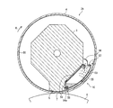
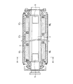
図1及び図2は、本発明の第1実施形態としてのロール装置用油回収装置を説明するためのもので、図1はロール装置をロール軸方向に垂直な面で切断した断面図、図2は図1のA方向矢視図(ロール外套は断面図で示す)を示している。なお、図1中の矢印R1はロール外套の回転方向を示す。
Hereinafter, embodiments of the present invention will be described with reference to the drawings.
(A) 1st Embodiment FIG.1 and FIG.2 is for demonstrating the oil collection | recovery apparatus for roll apparatuses as 1st Embodiment of this invention, FIG. 1 is a surface perpendicular | vertical to a roll axial direction. FIG. 2 is a sectional view taken along the direction A in FIG. 1 (the roll mantle is shown in a sectional view). Arrows R 1 in Figure 1 indicates the rotational direction of the roll mantle.
本実施形態に係るロール装置用油回収装置1A,1Bは、例えば抄紙機のプレス装置やカレンダ装置などに設けられたロール装置2に装備される。まず、このロール装置2について説明すると、ロール装置2は、図1に示すように、ロール軸方向(装置幅方向)に設けられ静止したセンターシャフト(支持体)3と、センターシャフト3を覆うようにセンターシャフト3の軸周りに配設され、軸端部に設けられた図示しない駆動装置により回転駆動する円筒状のロール外套4と、センターシャフト3の上部に支持されロール外套4を内周側から周外部向に押圧するシュー5とを主に備えて構成されている。
The roll apparatus
なお、シュー5については、シュー5をロール軸方向において複数に分割して、これらの各シュー5による押圧力を独立に調整することで、ロール外套4の軸方向外形の形状を調整(クラウンコントロール)できるようにした、マルチシュータイプ・コントロールド・クラウン・ロール(M.C.C.R)として構成してもよい。また、ロール外套4は自ら回転駆動力を受けて回動する回転駆動式のものの他、従動式のものでもよい。
For the
また、図1及び図2では、本ロール装置用油回収装置1A,1Bが適用されるロール装置2の1つのモデルを示している。従って、例えば、ここではセンターシャフト3を六角形の形状で示しているが、センターシャフト3はこの形状に限定されるものではなく任意の形状であっても良く、また、シュー5の詳細な構成についてはここでは省略して示しているが、シュー5を例えば前述した従来技術のシューと同様の構成としてもよい。さらに、本実施形態では、図1及び図2に示すように、ロール装置2が対向ロール6の下方に配置される場合について示している。
Moreover, in FIG.1 and FIG.2, one model of the
このようなロール装置2では、ロール外套4の内周面とシュー5との摺接部7の摩擦係数を小さくしてロール外套4を円滑に回転させるためにロール外套4内に油(潤滑油)50を供給して摺動部7に油膜を形成するようになっているが、前述したように、ロール外套4の回転速度が速くなると、ロール外套4内の油50は図1中の矢印R3に示すように摺接部7に激しく衝突してロール外套4の回転方向上流側の一帯にしぶき状の反転流として跳ね返る。
In such a
本ロール装置用油回収装置1Aは、上記のように摺接部7に激しく衝突して回転方向上流側に跳ね返ってくる油50を効率よく回収するように構成されている。具体的には、本ロール装置用油回収装置1Aは、図1及び図2に示すように、摺接部7の下方で且つ摺接部7よりもロール外套4の回転方向上流側に設けられた油受け皿としての油回収パン(第1の油回収パン)8を備えて構成されている。また、油回収パン8の開口部は、摺接部7に衝突して跳ね返ってくる油50を略全て捕獲するのに十分な大きさに形成されている。さらに、油回収パン8はロール軸方向に延設されており、油回収パン8の一側部8aがボルト9によりセンターシャフト3に取り付けられている。
The
特に、図1に示すように、油回収パン8の他側部8bには、ロール軸方向に延設された油飛散防止板(油飛散防止部材)10がボルト11により取り付けられている。この油飛散防止板10は、その上端部(外縁上端部)12がロール外套4内で連れ回りする油膜と干渉しない範囲で且つロール外套4内に接近した位置に配置されるように取り付けられている。また、図2に示すように、油回収パン8の油飛散防止板10が取り付けられる他側部8bのボルト孔は、ロール外套4の内周面へ向かって延びる長孔13で形成されている。通常、油膜の厚さは運転条件などにより変化するが、上記のような長孔13により油飛散防止板10をロール外套4の内周面に対して接離させることが可能であるため、油飛散防止板10を油膜の厚さに対応した適宜の位置に変更することができるようになっている。
In particular, as shown in FIG. 1, an oil scattering prevention plate (oil scattering prevention member) 10 extending in the roll axis direction is attached to the
また、図1及び図2に示すように、油回収パン8内の底部には、排油口14が形成されているとともに、油回収パン8により回収された油50が排油口14へ流入しやすくするためにロール軸方向に傾斜した傾斜板15が備えられている。さらに、センターシャフト3内には、排油口14に接続する配管16と、配管16に接続し、センターシャフト3軸方向に延びて油50をロール装置2の外部へ排出する配管17とが形成されている。これにより、油回収パン8により回収された油50は、傾斜板15を伝って排油口14へ流入し、配管16及び配管17を通って、図2中の矢印R4で示すようにロール装置2の外部へ排出されるようになっている。なお、このようにロール装置2の外部へ排出された油50は、冷却等の適宜の処理が行なわれた後、図2中の矢印R4′で示すようにセンターシャフト3の軸端部に形成された給油口18やシュー5を介してロール外套4内に供給されるようになっている。
As shown in FIGS. 1 and 2, an
また、図1に示すように、本ロール装置用油回収装置1Bは、摺接部7の下方で且つ摺接部7よりもロール外套4の回転方向下流側に設けられ、ロール外套4の回転に伴ってロール外套4内で連れ回りする油50を回収する油回収パン(第2の油回収パン)20と、油回収パン20の上方に設けられ、先端部21をロール外套4の内周面に摺接してロール外套4内で連れ回りする油50を掻き取って油回収パン20内に導く掻き取りブレード22とを主に備えて構成されている。
Further, as shown in FIG. 1, the roll apparatus oil recovery apparatus 1 </ b> B is provided below the sliding
さらに、油回収パン20の開口部は、掻き取りブレード22により掻き取られる油50を略全て捕獲するのに十分な大きさに形成されている。さらに、油回収パン20はロール軸方向に延設されており、油回収パン20の一側部20aがボルト23によりセンターシャフト3に取り付けられている。
また、掻き取りブレード22はロール軸方向に延設されている。さらに、掻き取りブレード22の先端部21のロール外套4の内周面に対する押圧力を調整する調整手段30が備えられている。この調整手段30は、油回収パン20の他側部20bの内側にボルト24により取り付けられた第1の支持部材25と、第1の支持部材25の上部に取り付けられたゴムチューブ26と、ボルト27によりゴムチューブ26の上部に取り付けられた第2の支持部材28とを備えて構成されており、掻き取りブレード22は、上記の第2の支持部材28の上部に取り付けられている。
Further, the opening of the
Further, the
また、図示は省略するが、第2の支持部材28のボルト孔は図1の上下方向に延びた長孔で形成されているとともに、ボルト27はこのボルト孔に遊嵌されている。これにより、第2の支持部材28は上下方向にボルト孔の長さ分(所定距離)だけ移動可能となっている。つまり、ゴムチューブ26内の空気などの圧縮性流体の圧力を制御してゴムチューブ26を空気ばねとして機能させ、第2の支持部材28を上下方向へ支持することにより、掻き取りブレード22をロール外套4の内周面に対してソフトに圧接させるようになっている。なお、掻き取りブレード22は第2の支持部材28に対して取り外し可能になっており、掻き取りブレード22の先端部21が摩耗したら容易に取替えることができるようになっている。
Although not shown, the bolt hole of the second support member 28 is formed as a long hole extending in the vertical direction in FIG. 1, and the
さらに、図1に示すように、油回収パン20内の底部には、排油口29が形成されているとともに、油回収パン20により回収された油50が排油口29へ流入しやすくするためにロール軸方向に傾斜した傾斜板31が備えられている。さらに、センターシャフト3内には、排油口29に接続する配管32が形成されており、この配管32は配管17に接続されている。これにより、油回収パン20により回収された油50は、傾斜板31を伝って排油口29へ流入し、配管32及び配管17を通ってロール装置2の外部へ排出されるようになっている。
Further, as shown in FIG. 1, an
本発明の第1実施形態としてのロール装置用油回収装置は、上述のごとく構成されているので、ロール装置用油回収装置1Aにより、ロール外套4内で連れ回りする油50により形成される油膜に干渉することなく、摺接部7に激しく衝突してロール外套4の回転方向上流側の一帯に跳ね返った油50までも効率よく且つ確実に回収することができる。つまり、ロール外套4の高速回転時においても、油回収率を向上させることができる。
Since the roll apparatus oil recovery apparatus according to the first embodiment of the present invention is configured as described above, the oil film formed by the
また、ロール装置用油回収装置1Bによれば、ロール外套4の内周面にソフトに圧接する掻き取りブレード22により、ロール外套4内周の油50を掻き取ることでロール外套4内周の油膜をロール外套内面に傷をつけるなどの悪影響を及ぼすことなく、また、油を余すことなく回収することができ、ロール装置用油回収装置1Aの効果と同様に、ロール外套4の高速回転時においても、油回収率を向上させることができる。
Further, according to the
なお、本実施形態では、ロール装置用油回収装置1A及びロール装置用油回収装置1Bの両方を設ける構成としたが、ロール装置用油回収装置1A及びロール装置用油回収装置1Bの何れか一方を設ける構成としてもよい。
In this embodiment, both the roll device
図3は、本ロール装置用油回収装置1Aを、上記のロール装置2とは別のロール装置2′に適用した例を示している。図3に示すロール装置用油回収装置1A′は、上述した第1実施形態に係るロール装置用油回収装置1Aと略同様の構成をしている。つまり、油飛散防止板10′の上端部12′が油膜と干渉しない範囲で、ロール外套4の内周面に接近した位置まで延設されている。また、油回収パン8′により回収された油50は、排油口14′を通してロール装置2′の外部へ排出されるようになっている。さらに、第1実施形態ではシュー5の詳細な説明を省略したが、このロール装置2′に係るシュー5′は、作動油供給管35を通して圧力室36に供給される作動油により上下方向に駆動するようになっている。ロール装置用油回収装置1A′は、このようなロール装置2′にも適用することができ、第1実施形態と同様の効果、即ち、摺接部7に激しく衝突してロール外套4の回転方向上流側の一帯に跳ね返った油50までも効率よく且つ確実に回収することができるという効果が得られる。
FIG. 3 shows an example in which the roll apparatus oil recovery apparatus 1 </ b> A is applied to a
(B)第2実施形態
図4は、本発明の第2実施形態としてのロール装置用油回収装置を説明するためのもので、ロール装置をロール軸方向に垂直な面で切断した断面図を示している。なお、図4において、前述した第1実施形態(図1,図2)と同一の部位又は部材については同一の符号を用いて示している。
(B) 2nd Embodiment FIG. 4 is for demonstrating the oil recovery apparatus for roll apparatuses as 2nd Embodiment of this invention, and is sectional drawing which cut | disconnected the roll apparatus by the surface perpendicular | vertical to a roll axial direction. Show. In FIG. 4, the same parts or members as those in the first embodiment (FIGS. 1 and 2) described above are denoted by the same reference numerals.
本実施形態に係るロール装置用油回収装置1Cは、対向ロール6の上部に設けられたロール装置2Aに装備されるものである。まず、このロール装置2Aについて説明すると、ロール装置2Aは、図4に示すように、ロール軸方向(装置幅方向)に設けられ静止したセンターシャフト(支持体)3と、センターシャフト3を覆うようにセンターシャフト3の軸周りに配設され、軸端部に設けられた図示しない駆動装置により回転駆動する円筒状のロール外套4と、センターシャフト3の下部に支持されロール外套4を内周側から周外方向に押圧するシュー5とを主に備えて構成されている。なお、図4では、本ロール装置用油回収装置1Cが適用されるロール装置2Aの1つのモデルを示している。従って、例えば、ここではセンターシャフト3を六角形の形状で示しているが、センターシャフト3はこの形状に限定されるものではなく任意の形状であっても良く、また、シュー5の詳細な構成についてはここでは省略して示しているが、シュー5を例えば前述した従来技術のシューと同様の構成としてもよい。
The roll apparatus oil recovery apparatus 1 </ b> C according to the present embodiment is equipped with a
このようなロール装置2Aでは、ロール外套4の内周面とシュー5との摺接部7の摩擦係数を小さくしてロール外套4を円滑に回転させるためにロール外套4内に油(潤滑油)50を供給して摺動部7に油膜を形成するようになっているが、前述したように、ロール外套4の回転速度が速くなると、ロール外套4内の油50は摺接部7に激しく衝突してロール外套4の回転方向上流側の一帯に跳ね返る。
In such a
本ロール装置用油回収装置1Cは、第1実施形態に係るロール装置用油回収装置1Aと同様に、上記のように摺接部7に激しく衝突して回転方向上流側に跳ね返ってくる油50を効率よく回収するように構成されている。具体的には、本ロール装置用油回収装置1Cは、センターシャフト3に支持されてロール外套4内に設けられた油回収パン(油回収流路)55と、摺接部7よりもロール外套4の回転方向上流側に開口部54aを有し、ロール外套4の回転に伴ってロール外套4内で連れ回りする油50をシュー5で堰き止めて油50の動圧を静圧に変えることにより生じるロール外套4内の圧力との圧力差を利用して上記開口部54aから回収して油回収パン55内に導くサイフォン流路54と、サイフォン流路54の開口部54a付近へ油50を確実に導入するように案内する油導入流路53とを主に備えて構成されている。
This roll apparatus oil recovery apparatus 1C, like the roll apparatus
油回収パン55は、摺接部7のロール外套4の回転方向上流側に配置されているとともに、油回収パン55はロール軸方向に延設されている。また、油回収パン55は、ロール外套4の内周面、及び、シュー5の側面(ロール外套4の回転方向上流側の面)、及び、センターシャフト3の側面(ロール外套4の回転方向上流側の面)のそれぞれに沿う面を備えて構成されている。油導入流路53は、このような油回収パン55とロール外套4の内周面とから形成される空間で形成され、また、サイフォン流路54は、油回収パン55とシュー5及びセンターシャフト3とから形成される空間で形成されている。
The
また、サイフォン流路54の出口に対向する位置には、サイフォン流路54の出口から噴き出す油50の飛散を防止して油50を確実に油回収パン55内に回収するためのカバー部材56が備えられている。このカバー部材56は、油回収パン55と同等の軸方向長さで形成され、油回収パン55にボルト57により取り付けられている。また、油回収パン55内の底部には、油回収パン55により回収された油50をロール装置2Aの外部へ排出するための排油口58が設けられている。なお、ロール装置2の外部へ排出された油50は、冷却等の適宜の処理が行なわれた後、ロール外套4内に供給され循環するようになっている。
Further, at a position facing the outlet of the siphon
本発明の第2実施形態としてのロール装置用油回収装置1Cは、上述のごとく構成されているので、まず、摺接部7のロール外套4の回転方向上流側において、ロール外套4内で連れ回りする油50は、油導入流路53に導入されて、シュー5で堰き止められることにより動圧から静圧に変換される。これにより、開口部54aにはサイフォン流路54の水頭圧よりも高い大きな圧力が発生し、この圧力によって、油50は、サイフォン流路54の開口部54aからサイフォン流路54を流れ、油回収パン55内に回収される。
Since the roll device oil recovery apparatus 1C according to the second embodiment of the present invention is configured as described above, first, the
このように、本ロール装置用油回収装置1Cによれば、油50を摺接部7に激しく衝突させることなく、効率よく且つ確実に回収することができる。つまり、第1実施形態と同様に、ロール外套4の高速回転時においても、油回収率を向上させることができる。
Thus, according to this roll apparatus oil recovery apparatus 1 </ b> C, the
(C)第3実施形態
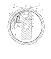
図5は、本発明の第3実施形態としてのロール装置用油回収装置を説明するためのもので、(a)はロール装置をロール軸方向に垂直な面で切断した断面図、(b)はその要部を拡大した拡大図を示している。なお、図5において、前述した第1実施形態(図1,図2)と同一の部位又は部材については同一の符号を用いて示している。
(C) Third Embodiment FIG. 5 is a view for explaining an oil recovery device for a roll device as a third embodiment of the present invention, and (a) is a cut view of the roll device along a plane perpendicular to the roll axial direction. Sectional drawing made, (b) shows an enlarged view of the main part. In FIG. 5, the same parts or members as those in the first embodiment (FIGS. 1 and 2) are denoted by the same reference numerals.
本実施形態に係るロール装置用油回収装置1Dは、第1実施形態と同様に、対向ロール6の下部に設けられたロール装置2に装備されるものである。従って、このロール装置2の構成は第1実施形態と同様であるのでここではその説明を省略する。
The roll apparatus
図5(a)に示すように、本ロール装置用油回収装置1Dは、センターシャフト3下部のロール外套4の回転方向下流側にボルト66により取り付けられ、先端部62がロール外套4の内周面に摺接する油回収部材60を備えて構成されている。また、図5(b)に示すように、この油回収部材60はロール軸方向に延設されており、油回収部材60の内部にはロール軸方向に延びる油回収流路63が形成されている。さらに、この油回収流路63はロール装置2の外部へ接続されている。
As shown in FIG. 5 (a), the
また、油回収部材60の先端部62には、ロール外套4の回転に伴ってロール外套4内で連れ回りする油50の流れ方向下流に向けてロール外套4の内周面に次第に接近していくように配設された油回収用楔形成面64が形成されている。また、この油回収用楔形成面64には、ロール軸方向に複数の開口部65が並んで形成されているとともに、油回収部材60の内部には、ロール外套4の内周面と油回収用楔形成面64とで形成される楔状空間に生じる楔効果によって、ロール外套4内で連れ回りする油50を、上記の開口部65から回収して油回収流路63に導く連絡流路61が形成されている。
Further, the
また、油回収用楔形成面64とロール外套4の内周面との間の隙間は、上流部では、油膜の厚さ以上(即ち、油膜の厚さよりも大きく又は略同等)に設定され〔図5(b)中の符号D1参照〕、下流部では、油膜の厚さよりも小さく(即ち、D1よりも小さく)設定されている。なお、ここでいう油膜の厚さとは、上記の隙間に進入する油膜の厚さのことをいい、特に、ロール外套4の高速回転時における油膜の厚さに対応して上記の隙間を設定することが好ましい。また、上記では、油回収用楔形成面64にロール軸方向にわたって複数の開口部65を形成する構成としたが、ロール軸方向にわたってスリット状の開口部を形成する構成としてももちろんよい。
In addition, the gap between the oil collecting
本発明の第3実施形態としてのロール装置用油回収装置1Dは、上述のごとく構成されているので、ロール外套4内で連れ回りする油50は、油回収部材60の油回収用楔形成面64とロール外套4の内周面との間の楔状空間に入り込み、この楔状空間の楔効果による圧力を受けて開口部65から連絡流路61を通って油回収流路63内に回収され、その後、油回収流路63からロール装置2の外部へ排出される。
Since the roll device
このように、本ロール装置用油回収装置1Dによれば、ロール外套4内で連れ回りする油50を、油回収部材60の油回収用楔形成面64とロール外套4の内周面とから形成された楔状空間の楔効果によって生じる圧力を利用して、効率よく且つ確実に回収することができる。つまり、第1実施形態と同様に、ロール外套4の高速回転時においても、油回収率を向上させることが可能となる。
As described above, according to the
また、油回収用楔形成面64とロール外套4の内周面との間の隙間を、上流部では、油膜の厚さ以上に設定し、下流部では、油膜の厚さよりも小さく設定しているので、油をロール外套4の内周面と油回収用楔形成面64とで形成される楔状空間に円滑に導入させることができる。
In addition, the gap between the oil collecting
(D)第4実施形態
図6は一般的なS.L.C.C.R(セルフ・ローディング・コントロールド・クラウン・ロール)の一例を示す軸方向断面図であり、図7は本発明の第4実施形態としてのロール装置用油回収装置を説明するためのもので、図6のA−A断面図である。なお、図6は、対向ロール(図示省略)の下方に配置されるS.L.C.C.Rを示しており、図7に示す矢印R1はロール外套4の回転方向を示している。また、図6及び図7において、前述した第1実施形態(図1,図2)と同一の部位又は部材については同一の符号を用いて示している。
(D) Fourth Embodiment FIG. L. C. C. FIG. 7 is an axial cross-sectional view showing an example of R (self-loading controlled crown roll), and FIG. 7 is for explaining an oil recovery apparatus for a roll apparatus as a fourth embodiment of the present invention; It is AA sectional drawing of FIG. FIG. 6 shows an S.P. disposed below the opposing roll (not shown). L. C. C. R denotes an arrow R 1 shown in FIG. 7 indicates the rotation direction of the roll mantle 4. 6 and 7, the same parts or members as those of the first embodiment (FIGS. 1 and 2) described above are denoted by the same reference numerals.
図6に示すように、S.L.C.C.Rは、センターシャフト3の上側及び下側の両側にそれぞれ複数のシュー5を備えて構成されている。ここでは、センターシャフト3の上側には3つのシュー5T1,5T2,5T3を備え、下側に2つのシュー5S1,5S2を備えたものを示している。このようなS.L.C.C.Rでは、シュー5T1,5T2,5T3を油圧などにより図6中の上下方向にそれぞれ別個に駆動させることができるようになっている。このようなシュー5T1,5T2,5T3によりロール外套4を上下動させることで対向ロール6とのニップを形成することができるので、ロール全体を上下動するためのアーム機構は必要としない。また、シュー5T1,5T2,5T3の圧力分布を調整することで、ロール外套4に対する押圧力をロール軸方向において細かく調整できるので、センターシャフト3の撓みにより生じるニップ圧変化やロール外套4のクラウン形状を補正することができる。また、シュー5S1,5S2も、シュー5T1,5T2,5T3と同様に油圧などにより上下方向にそれぞれ別個に駆動させることができるようになっている。
As shown in FIG. L. C. C. R is configured to include a plurality of
シュー5T2に作用する油圧をシュー5T1,5T3に作用する油圧よりも大きくしてロール外套4をクラウン形状(凸状)にする場合には、シュー5S1,5S2に作用する油圧を大きくしてシュー5S1,5S2を図6中の下方向に駆動させ、ロール両軸端に荷重を作用させて曲げモーメントを加えることで、所望のクラウン形状を得ることができる。また、シュー5T2に作用する油圧をシュー5T1,5T3に作用する油圧よりも小さくしてロール外套4をディスクラウン形状(凹状)にする場合には、シュー5S1,5S2に作用する油圧を小さくしてシュー5S1,5S2を図6中の上方向に駆動させることで所望のディスクラウン形状を得ることができる。これにより、ロール外套4の断面形状が過度に変形するのを防止しながら対向ロール6に対するニップ圧を制御できるようになっている。なお、このようなS.L.C.C.Rは、例えば抄紙機のプレス装置のセンターロールやカレンダ装置のカレンダロールとして用いられる。
When the hydraulic pressure acting on the shoe 5T 2 is made larger than the hydraulic pressure acting on the shoes 5T 1 , 5T 3 and the roll mantle 4 is crowned (convex), the hydraulic pressure acting on the shoes 5S 1 , 5S 2 is increased. The desired crown shape can be obtained by enlarging and driving the shoes 5S 1 and 5S 2 downward in FIG. 6 and applying a load to both roll shaft ends to apply a bending moment. In addition, when the hydraulic pressure acting on the shoe 5T 2 is made smaller than the hydraulic pressure acting on the shoes 5T 1 and 5T 3 and the roll mantle 4 is made into a crown shape (concave shape), it acts on the shoes 5S 1 and 5S 2 . A desired discrown shape can be obtained by reducing the hydraulic pressure and driving the shoes 5S 1 and 5S 2 upward in FIG. Thereby, the nip pressure with respect to the opposing
本ロール装置用油回収装置は、このようなS.L.C.C.Rに適用されるもので、第1実施形態で説明したロール装置用油回収装置1A,1Bと同様の構成である。すなわち、図7に示すように、シュー5T1よりも回転方向上流側にロール軸方向に延びたロール装置用油回収装置1Aが取り付けられ、また、シュー5T1よりも回転方向下流側にロール軸方向に延びたロール装置用油回収装置1Bが取り付けられて構成されている。
The oil recovery apparatus for the roll apparatus is an S.I. L. C. C. It is applied to R and has the same configuration as the roll device
このように、第1実施形態に係るロール装置用油回収装置1A及びロール装置用油回収装置1Bを、S.L.C.C.Rにも適用することができ、ロール外套4内で連れ回りする油50により形成される油膜に干渉することなく、摺接部7に激しく衝突してロール外套4の回転方向上流側の一帯に跳ね返った油50までも効率よく且つ確実に回収することができる。つまり、ロール外套4の高速回転時においても、油回収率を向上させることができる。また、ロール外套4の内周面にソフトに圧接する掻き取りブレード22により、ロール外套4内周の油50を掻き取ることでロール外套4内面に傷をつけるなどの悪影響を及ぼすことなく、また、ロール外套4内周の油を余すことなく回収して、ロール装置用油回収装置1Aの効果と同様に、ロール外套4の高速回転時においても、油回収率を向上させることができる。
As described above, the roll apparatus
なお、S.L.C.C.Rではロール外套4が上下動すること或いはクラウン形状が変化することによりロール装置用油回収装置1Aの油飛散防止板10とロール外套4との間の隙間が大きくなる場合があるが、油飛散防止板10が設けられていることにより従来に比べて油回収率を向上させることが可能となっている。また、油飛散防止板10をロール外套4に対して接離する駆動装置を設けて油飛散防止板10のロール外套4に対する距離を調整するようにしてもよく、このように構成すれば、より確実に油回収率を向上させることが可能となる。
S. L. C. C. In R, when the roll mantle 4 moves up and down or the crown shape changes, the gap between the oil
また、本実施形態では、S.L.C.C.Rにロール装置用油回収装置1A,1Bを備える構成としたが、ロール装置用油回収装置1A,1B,1C,1Dのうちの少なくとも1つ、或いは、組み合わせて備えるようにしてもよい。
In this embodiment, S.I. L. C. C. Although it was set as the structure provided with
(E)その他
以上、本発明の実施形態について説明したが、本発明は上記の実施形態に限定されるものではなく、本発明の趣旨を逸脱しない範囲で種々変形して実施することができる。例えば、第1実施形態に係るロール装置2において、ロール装置用油回収装置1A,1Bの他に、ロール装置用油回収装置1Dをさらに装備する構成としてもよい。
(E) Others Although the embodiment of the present invention has been described above, the present invention is not limited to the above embodiment, and various modifications can be made without departing from the spirit of the present invention. For example, in the
また、第1実施形態に係るロール装置2において、ロール装置用油回収装置1Bは設けずにロール装置用油回収装置1Aだけを設け、さらに第3実施形態に係るロール装置用油回収装置1Dを設ける構成としてもよい。
さらに、第2実施形態に係るロール装置2Aにおいて、ロール装置用油回収装置1Cの他に、第3実施形態に係るロール装置用油回収装置1Dをさらに装備する構成としてもよい。
Further, in the
Furthermore, in the
また、第1実施形態及び第3実施形態ではセンターシャフト3の上部にシュー5を備えたロール装置2について説明したが、例えば第4実施形態のS.L.C.C.Rのように、このセンターシャフト3の下部にも他のシューを備える構成とした場合には、このセンターシャフト3下部よりもロール外套4の回転方向上流側に、第2実施形態に係るロール装置用油回収装置1Cを備えてもよい。
In the first embodiment and the third embodiment, the
1A,1A′,1B,1C,1D ロール装置用油回収装置
2,2′,2A ロール装置
3,3′ センターシャフト
4 ロール外套
5,5′,5T1,5T2,5T3,5S1,5S2 シュー
6 対向ロール
7 摺接部
8,8′ 油回収パン(第1の油回収パン)
8a 一側部
8b 他側部
9 ボルト
10,10′ 油飛散防止板
11 ボルト
12,12′ 先端部
13 長孔
14,14′ 排油口
15 傾斜板
16,17 配管
18 給油口
20 油回収パン(第2の油回収パン)
20a 一側部
20b 他側部
21 先端部
22 掻き取りブレード
23,24 ボルト
25 第1の支持部材
26 ゴムチューブ
27 ボルト
28 第2の支持部材
29 排油口
30 調整手段
31 傾斜板
32 配管
35 作動油供給管
36 圧力室
53 油導入流路
54 サイフォン流路
54a 開口部
55 油回収パン(油回収流路)
56 カバー部材
57 ボルト
58 排油口
60 油回収部材
61 連絡流路
62 先端部
63 油回収流路
64 油回収用楔形成面
65 開口部
66 ボルト
1A, 1A ', 1B, 1C , 1D roll apparatus
8a One
20a One
56
Claims (8)
該シューの摺接部が該ロール外套内の上部に位置するとともに、
該摺接部の下方で且つ該摺接部よりも該ロール外套の回転方向上流側に設けられ、該ロール外套の回転に伴って該ロール外套内で連れ回りする油を回収する油回収パンをそなえ、
該油回収パンの外縁上端部が、該ロール外套内で連れ回りする油により形成される油膜と干渉しない範囲で、該ロール外套内周面に接近した位置まで延設されている
ことを特徴とする、ロール装置用油回収装置。 A roll apparatus comprising a stationary support, a roll mantle that is disposed around the support and rotates, and a shoe that is supported by the support and presses the roll mantle from the inner circumference side toward the outer circumference. An oil recovery device for a roll device that is equipped and recovers oil in the roll mantle,
The sliding contact portion of the shoe is located at the upper part in the roll mantle,
An oil recovery pan that is provided below the sliding contact portion and upstream of the sliding contact portion in the rotation direction of the roll mantle, and collects oil that rotates along with the roll mantle as the roll mantle rotates. In addition,
The upper end of the outer edge of the oil recovery pan is extended to a position close to the inner peripheral surface of the roll mantle as long as it does not interfere with the oil film formed by the oil that rotates in the roll mantle. Oil collecting device for roll device.
ことを特徴とする、請求項1記載のロール装置用油回収装置。 The oil recovery device for a roll device according to claim 1, wherein an upper end portion of an outer edge of the oil recovery pan is configured to be able to adjust contact / separation with respect to the inner surface of the roll mantle.
該シューの摺接部が該ロール外套内の上部に位置するとともに、
該摺接部の下方で且つ該摺接部よりも該ロール外套の回転方向下流側に設けられ、該ロール外套の回転に伴って該ロール外套内で連れ回りする油を回収する油回収パンと、
該油回収パンの上方に設けられ、先端部を該ロール外套内周面に摺接して該ロール外套内で連れ回りする油を掻き取って該油回収パンに導く掻き取りブレードとをそなえている
ことを特徴とする、ロール装置用油回収装置。 A roll apparatus comprising a stationary support, a roll mantle that is disposed around the support and rotates, and a shoe that is supported by the support and presses the roll mantle from the inner circumference side toward the outer circumference. An oil recovery device for a roll device that is equipped and recovers oil in the roll mantle,
The sliding contact portion of the shoe is located at the upper part in the roll mantle,
An oil recovery pan that is provided below the sliding contact portion and downstream of the sliding contact portion in the rotation direction of the roll mantle, and collects oil that rotates in the roll mantle as the roll mantle rotates. ,
A scraper blade is provided above the oil recovery pan, scrapes the oil that rotates along the inner surface of the roll mantle and scrapes the oil that rotates along the inner surface of the roll mantle, and guides the oil to the oil recovery pan. An oil recovery device for a roll device.
ことを特徴とする、請求項3記載のロール装置用油回収装置。 4. The oil recovery apparatus for a roll apparatus according to claim 3, further comprising an adjusting means for adjusting a pressing force of the tip end portion of the scraping blade against the inner surface of the roll mantle.
該シューの摺接部が該ロール外套内の下部に位置するとともに、
該支持体に支持されて該ロール外套内に設けられた油回収流路と、
該摺接部よりも該ロール外套の回転方向上流側に開口し、該ロール外套の回転に伴って該ロール外套内で連れ回りする油を、圧力差を利用して該開口部から回収して該油回収流路に導くサイフォン流路とをそなえている
ことを特徴とする、ロール装置用油回収装置。 A roll apparatus comprising a stationary support, a roll mantle that is disposed around the support and rotates, and a shoe that is supported by the support and presses the roll mantle from the inner circumference side toward the outer circumference. An oil recovery device for a roll device that is equipped and recovers oil in the roll mantle,
The sliding contact portion of the shoe is located in the lower part of the roll mantle,
An oil recovery flow path supported by the support and provided in the roll mantle;
The oil that opens to the upstream side in the rotation direction of the roll mantle from the sliding contact portion and rotates along the roll mantle as the roll mantle rotates is recovered from the opening using a pressure difference. An oil recovery apparatus for a roll device, comprising a siphon flow path leading to the oil recovery path.
ことを特徴とする、請求項5記載のロール装置用油回収装置。 6. An oil recovery apparatus for a roll apparatus according to claim 5, further comprising an oil introduction flow path for introducing oil into the vicinity of the opening of the siphon flow path.
該支持体に支持されて該ロール外套内に設けられた油回収流路と、
該支持体に支持されるとともに、該ロール外套の回転に伴って該ロール外套内で連れ回りする油の流れ方向下流に向けて該ロール外套内周面に次第に接近していくように配設された油回収用楔形成面と、
該油回収用楔形成面に開口し、該ロール外套内周面と該油回収用楔形成面とで形成される楔状空間に生じる楔効果によって、該ロール外套内で連れ回りする油を、該開口部から回収して該油回収流路に導く連絡流路とをそなえている
ことを特徴とする、ロール装置用油回収装置。 A roll apparatus comprising a stationary support, a roll mantle that is disposed around the support and rotates, and a shoe that is supported by the support and presses the roll mantle from the inner circumference side toward the outer circumference. An oil recovery device for a roll device that is equipped and recovers oil in the roll mantle,
An oil recovery flow path supported by the support and provided in the roll mantle;
It is supported by the support, and is arranged so as to gradually approach the inner peripheral surface of the roll mantle toward the downstream in the flow direction of the oil that rotates in the roll mantle as the roll mantle rotates. Oil collecting wedge forming surface;
Oil that is rotated in the roll mantle is opened by the wedge effect formed in a wedge-shaped space that is opened in the oil collecting wedge forming surface and is formed by the inner surface of the roll mantle and the oil collecting wedge forming surface. An oil recovery apparatus for a roll device, comprising a communication flow path that is recovered from an opening and led to the oil recovery flow path.
ことを特徴とする、請求項7記載のロール装置用油回収装置。 The gap between the oil recovery wedge forming surface and the inner surface of the roll mantle is set to be larger or substantially equal to the thickness of the oil film formed by the oil that rotates in the roll mantle at the upstream portion. 8. The oil recovery device for a roll device according to claim 7, wherein the downstream portion is set smaller than the thickness of the oil film.
Priority Applications (10)
| Application Number | Priority Date | Filing Date | Title |
|---|---|---|---|
| JP2004030933A JP2005221027A (en) | 2004-02-06 | 2004-02-06 | Oil collecting device for roll device |
| US11/002,123 US7575544B2 (en) | 2004-02-06 | 2004-12-03 | Oil recovery apparatus for a roll apparatus |
| EP06121337A EP1734267B1 (en) | 2004-02-06 | 2004-12-15 | Roll apparatus with oil recovery apparatus |
| EP04029734A EP1561959B1 (en) | 2004-02-06 | 2004-12-15 | Roll apparatus with oil recovery apparatus |
| DE602004022770T DE602004022770D1 (en) | 2004-02-06 | 2004-12-15 | Roller with oil recovery device |
| DE602004021858T DE602004021858D1 (en) | 2004-02-06 | 2004-12-15 | Roller with oil recovery device |
| CNA2005100078632A CN1651778A (en) | 2004-02-06 | 2005-02-06 | Oil recovery apparatus for a roll apparatus |
| CN2007100919406A CN101082191B (en) | 2004-02-06 | 2005-02-06 | Oil recovery apparatus for a roll apparatus |
| CNA2007100919393A CN101082190A (en) | 2004-02-06 | 2005-02-06 | Oil recovery apparatus for a roll apparatus |
| CNA2007100919410A CN101082192A (en) | 2004-02-06 | 2005-02-06 | Oil recovery apparatus for a roll apparatus |
Applications Claiming Priority (1)
| Application Number | Priority Date | Filing Date | Title |
|---|---|---|---|
| JP2004030933A JP2005221027A (en) | 2004-02-06 | 2004-02-06 | Oil collecting device for roll device |
Publications (1)
| Publication Number | Publication Date |
|---|---|
| JP2005221027A true JP2005221027A (en) | 2005-08-18 |
Family
ID=34675565
Family Applications (1)
| Application Number | Title | Priority Date | Filing Date |
|---|---|---|---|
| JP2004030933A Pending JP2005221027A (en) | 2004-02-06 | 2004-02-06 | Oil collecting device for roll device |
Country Status (5)
| Country | Link |
|---|---|
| US (1) | US7575544B2 (en) |
| EP (2) | EP1561959B1 (en) |
| JP (1) | JP2005221027A (en) |
| CN (4) | CN101082191B (en) |
| DE (2) | DE602004022770D1 (en) |
Families Citing this family (3)
| Publication number | Priority date | Publication date | Assignee | Title |
|---|---|---|---|---|
| DE102006034043A1 (en) * | 2006-07-24 | 2008-01-31 | Voith Patent Gmbh | press roll |
| DE202010014965U1 (en) | 2010-10-30 | 2011-01-05 | Andritz Küsters Gmbh | deflection |
| CN109706663A (en) * | 2019-03-05 | 2019-05-03 | 南充八度阳光科技有限公司 | A kind of flux controllable oiling device for carbon fiber production |
Family Cites Families (14)
| Publication number | Priority date | Publication date | Assignee | Title |
|---|---|---|---|---|
| FR2590650B1 (en) | 1985-11-22 | 1988-02-26 | Clecim Sa | DEFORMABLE ROTATING FREIGHT CYLINDER, PARTICULARLY FOR A ROLLER |
| US5189775A (en) | 1992-02-25 | 1993-03-02 | The Black Clawson Company | Zone controlled deflection compensated roll |
| DE4402754A1 (en) | 1994-01-31 | 1994-06-16 | Voith Gmbh J M | Pressure element - with collector unit in oil siphon system which is mounted at points least influenced by beam deflections |
| DE4420104C2 (en) | 1994-06-09 | 1997-04-24 | Voith Sulzer Papiermasch Gmbh | Support element |
| DE19534571C2 (en) | 1995-09-18 | 2001-06-28 | Voith Sulzer Papiermasch Gmbh | Device for a paper machine for conveying liquid from a first level to a second, higher level |
| DE19616802A1 (en) | 1996-04-26 | 1997-10-30 | Voith Sulzer Papiermasch Gmbh | Deflection compensation roller |
| DE19623652A1 (en) | 1996-06-13 | 1997-12-18 | Voith Sulzer Papiermasch Gmbh | Deflection adjustment roller |
| DE19703966A1 (en) | 1997-02-03 | 1998-08-06 | Voith Sulzer Papiermasch Gmbh | Belt press unit with fluid wiping device and method for operating the belt press unit |
| FI2920U1 (en) | 1997-02-28 | 1997-05-29 | Valmet Corp | Arrangement on a deflection-compensated roller with load shoes |
| FI114334B (en) | 1998-09-23 | 2004-09-30 | Metso Paper Inc | Equipment for deflection roller and method for controlling oil flow in deflection roller |
| DE19903843C1 (en) | 1999-02-01 | 2000-07-06 | Voith Sulzer Papiertech Patent | Roller for a web processing machine has inner supports at the cylinder mantle and scraper lips on levers with a take-off channel for the fluid leading to an offset collection zone |
| FI115790B (en) | 1999-07-06 | 2005-07-15 | Metso Paper Inc | Method and arrangement for removing oil from a press roll with variable bombing |
| SE515926C2 (en) | 1999-12-08 | 2001-10-29 | Valmet Karlstad Ab | Method and apparatus for oil evacuation from a shoe press unit |
| DE10154862A1 (en) | 2001-11-08 | 2003-05-22 | Voith Paper Patent Gmbh | Device for draining liquid |
-
2004
- 2004-02-06 JP JP2004030933A patent/JP2005221027A/en active Pending
- 2004-12-03 US US11/002,123 patent/US7575544B2/en not_active Expired - Fee Related
- 2004-12-15 EP EP04029734A patent/EP1561959B1/en not_active Expired - Fee Related
- 2004-12-15 DE DE602004022770T patent/DE602004022770D1/en active Active
- 2004-12-15 DE DE602004021858T patent/DE602004021858D1/en active Active
- 2004-12-15 EP EP06121337A patent/EP1734267B1/en not_active Expired - Fee Related
-
2005
- 2005-02-06 CN CN2007100919406A patent/CN101082191B/en not_active Expired - Fee Related
- 2005-02-06 CN CNA2007100919410A patent/CN101082192A/en active Pending
- 2005-02-06 CN CNA2005100078632A patent/CN1651778A/en active Pending
- 2005-02-06 CN CNA2007100919393A patent/CN101082190A/en active Pending
Also Published As
| Publication number | Publication date |
|---|---|
| EP1561959B1 (en) | 2009-08-26 |
| EP1734267A1 (en) | 2006-12-20 |
| CN101082191A (en) | 2007-12-05 |
| EP1734267B1 (en) | 2009-07-01 |
| CN101082190A (en) | 2007-12-05 |
| DE602004022770D1 (en) | 2009-10-08 |
| CN101082191B (en) | 2010-12-22 |
| EP1561959A1 (en) | 2005-08-10 |
| DE602004021858D1 (en) | 2009-08-13 |
| US7575544B2 (en) | 2009-08-18 |
| CN1651778A (en) | 2005-08-10 |
| US20050176563A1 (en) | 2005-08-11 |
| CN101082192A (en) | 2007-12-05 |
Similar Documents
| Publication | Publication Date | Title |
|---|---|---|
| EP2296817B1 (en) | Top service gyratory crusher | |
| RU2508942C2 (en) | Conical crusher thrust bearing and method of horizontal shaft support in such crusher | |
| JP4755603B2 (en) | Device for sealing the roll barrel side of the rolling roll neck bearing | |
| JP6469343B2 (en) | Solid fuel pulverizer and method of manufacturing solid fuel pulverizer | |
| CN102038274A (en) | Walnut sheller | |
| JP2009056423A (en) | Bucket type jaw crusher | |
| JP2007518573A5 (en) | ||
| JP2005221027A (en) | Oil collecting device for roll device | |
| CN100417429C (en) | Device for continuous filtration of material blends | |
| JP5855502B2 (en) | Multi-stage rolling mill | |
| JP5837758B2 (en) | Twin roll casting apparatus and control method thereof | |
| JP5668903B2 (en) | Vertical crusher | |
| JP6453029B2 (en) | Crushing device and method for adjusting bearing portion of crushing device | |
| JP5251448B2 (en) | Vertical mill | |
| CN112207622B (en) | Clean cooling device of machining center | |
| JP3379672B2 (en) | Roll machine | |
| CN107107066B (en) | Mills for disintegrating a bed of material by compression | |
| CN201014160Y (en) | Thermal straightening machine supporting roller bearing lubrication structure | |
| JP3752245B2 (en) | Garbage relief device for water intake | |
| CN213039811U (en) | Roller and roller end sealing device | |
| DE10031446A1 (en) | Removal of oil from within the rotating mantle of a roller with fixed supports has an oil guide at the mantle support near the auxiliary guide of the collection trough to give a smooth path without developing air bubbles | |
| JP5920573B2 (en) | Vertical crusher | |
| KR100295621B1 (en) | Scrap guide apparatus of wire rod | |
| CN112620540A (en) | Steel bar cutting machine | |
| JP2005224745A (en) | Shaft bearing structure of rotary shaft of crusher |
Legal Events
| Date | Code | Title | Description |
|---|---|---|---|
| A621 | Written request for application examination |
Free format text: JAPANESE INTERMEDIATE CODE: A621 Effective date: 20070117 |
|
| A711 | Notification of change in applicant |
Free format text: JAPANESE INTERMEDIATE CODE: A711 Effective date: 20080522 |
|
| A131 | Notification of reasons for refusal |
Free format text: JAPANESE INTERMEDIATE CODE: A131 Effective date: 20090714 |
|
| A02 | Decision of refusal |
Free format text: JAPANESE INTERMEDIATE CODE: A02 Effective date: 20100112 |