JP2005216632A - Battery pack - Google Patents
Battery pack Download PDFInfo
- Publication number
- JP2005216632A JP2005216632A JP2004020510A JP2004020510A JP2005216632A JP 2005216632 A JP2005216632 A JP 2005216632A JP 2004020510 A JP2004020510 A JP 2004020510A JP 2004020510 A JP2004020510 A JP 2004020510A JP 2005216632 A JP2005216632 A JP 2005216632A
- Authority
- JP
- Japan
- Prior art keywords
- welding
- side plate
- case
- rib
- plate
- Prior art date
- Legal status (The legal status is an assumption and is not a legal conclusion. Google has not performed a legal analysis and makes no representation as to the accuracy of the status listed.)
- Pending
Links
- 238000003466 welding Methods 0.000 claims abstract description 152
- 230000002265 prevention Effects 0.000 description 10
- 230000007423 decrease Effects 0.000 description 3
- 230000002950 deficient Effects 0.000 description 3
- XECAHXYUAAWDEL-UHFFFAOYSA-N acrylonitrile butadiene styrene Chemical compound C=CC=C.C=CC#N.C=CC1=CC=CC=C1 XECAHXYUAAWDEL-UHFFFAOYSA-N 0.000 description 2
- 229920000122 acrylonitrile butadiene styrene Polymers 0.000 description 2
- 239000004676 acrylonitrile butadiene styrene Substances 0.000 description 2
- 230000015572 biosynthetic process Effects 0.000 description 2
- 230000007547 defect Effects 0.000 description 2
- 238000004519 manufacturing process Methods 0.000 description 2
- 238000002844 melting Methods 0.000 description 2
- 230000008018 melting Effects 0.000 description 2
- 238000000034 method Methods 0.000 description 2
- 229920005989 resin Polymers 0.000 description 2
- 239000011347 resin Substances 0.000 description 2
- 239000000758 substrate Substances 0.000 description 2
- -1 and for example Polymers 0.000 description 1
- 229920000515 polycarbonate Polymers 0.000 description 1
- 239000004417 polycarbonate Substances 0.000 description 1
- 230000000452 restraining effect Effects 0.000 description 1
- 230000001629 suppression Effects 0.000 description 1
- 229920003002 synthetic resin Polymers 0.000 description 1
- 239000000057 synthetic resin Substances 0.000 description 1
Images

Classifications
-
- Y—GENERAL TAGGING OF NEW TECHNOLOGICAL DEVELOPMENTS; GENERAL TAGGING OF CROSS-SECTIONAL TECHNOLOGIES SPANNING OVER SEVERAL SECTIONS OF THE IPC; TECHNICAL SUBJECTS COVERED BY FORMER USPC CROSS-REFERENCE ART COLLECTIONS [XRACs] AND DIGESTS
- Y02—TECHNOLOGIES OR APPLICATIONS FOR MITIGATION OR ADAPTATION AGAINST CLIMATE CHANGE
- Y02E—REDUCTION OF GREENHOUSE GAS [GHG] EMISSIONS, RELATED TO ENERGY GENERATION, TRANSMISSION OR DISTRIBUTION
- Y02E60/00—Enabling technologies; Technologies with a potential or indirect contribution to GHG emissions mitigation
- Y02E60/10—Energy storage using batteries
Landscapes
- Battery Mounting, Suspending (AREA)
Abstract
Description
本発明は、底板及び該底板外周に形成された側板を有する第1ケース半体及び第2ケース半体の側板先端部どうしを溶着した電池ケースに電池が収納されている電池パックに関する。 The present invention relates to a battery pack in which a battery is housed in a battery case in which front plate end portions of side plates of a first case half and a second case half having a bottom plate and a side plate formed on the outer periphery of the bottom plate are welded.
小型電子機器又は携帯電子機器などの駆動用電源として、電池及び回路基板などを電池ケースに収納した電池パックが用いられている。前記電池ケースは、第1底板外周に形成された第1側板の先端部に突起状の溶着リブが形成された第1ケース半体と、第2底板外周に形成された第2側板の先端部に前記溶着リブが溶着される溶着面が形成された第2ケース半体とを備えており、超音波溶着などで溶着リブを溶着面に溶着して、第1ケース半体及び第2ケース半体を一体化している。 A battery pack in which a battery, a circuit board, and the like are housed in a battery case is used as a driving power source for a small electronic device or a portable electronic device. The battery case includes a first case half in which a protruding welding rib is formed at a front end portion of a first side plate formed on the outer periphery of the first bottom plate, and a front end portion of a second side plate formed on the outer periphery of the second bottom plate. And a second case half formed with a welding surface on which the welding rib is welded. The first case half and the second case half are welded to the welding surface by ultrasonic welding or the like. The body is integrated.
溶着リブを溶着面に溶着する場合、超音波溶着時に発生する振動の影響で、溶着リブの位置がずれることがあるため、溶着リブが溶着面から落ちないように、第2側板の厚さを大きくしたり、溶着面の外縁部に脱落防止リブを設けたり、溶着リブの先端をV字形にすると共に溶着面にV字溝を形成することが行われている(例えば、特許文献1参照)。
近年では、小型電子機器又は携帯電子機器などの軽薄短小化に伴って、前記電子機器に内蔵する電池パックの小型軽量化が強く望まれている。小型軽量化のためには、電池及び回路基板の小型化のみならず、電池ケースの小型軽量化が必要になる。電池ケースを小型軽量化する方法として、ケース半体の側板の肉厚を薄くすることが考えられるが、ケース半体の側板の肉厚を薄くする場合、側板先端部の溶着面が減少するため、溶着リブが溶着される位置精度が低下したり、溶着の強度が低下する可能性が高い。 In recent years, along with miniaturization of small electronic devices or portable electronic devices, there is a strong demand for reducing the size and weight of battery packs built into the electronic devices. In order to reduce the size and weight, not only the size of the battery and the circuit board but also the size and weight of the battery case must be reduced. As a method for reducing the size and weight of the battery case, it is conceivable to reduce the thickness of the side plate of the case half. However, if the thickness of the side plate of the case half is reduced, the welding surface of the side plate tip decreases. There is a high possibility that the position accuracy at which the welding rib is welded is lowered and the welding strength is lowered.
また、溶着面の外縁部に脱落防止リブを設けた場合、超音波溶着時の振動によって溶着リブが脱落防止リブ側に移動することにより、溶着リブを有する第1側板と脱落防止リブとが接触し、第1側板と脱落防止リブとが溶融することがある。そして、溶融した樹脂がケース内部に流れた場合、電池又は回路基板などの内蔵部品と干渉し、ケース半体の側板が変形するなどの外観不良が生じることがある。また、小型化のためにケース内面と電池との間隙はわずかであり、ケース内側に流れた溶融樹脂が内蔵部品からの圧力でケース外部に流れ出し、外観不良が生じることもある。 In addition, when a drop prevention rib is provided on the outer edge of the weld surface, the first rib having the weld rib and the drop prevention rib come into contact with each other when the weld rib moves to the drop prevention rib side due to vibration during ultrasonic welding. In addition, the first side plate and the drop-off preventing rib may melt. When the molten resin flows into the case, it may interfere with built-in components such as a battery or a circuit board, resulting in a defective appearance such as deformation of the side plate of the case half. Further, the gap between the inner surface of the case and the battery is small due to the miniaturization, and the molten resin that flows inside the case flows out to the outside of the case due to the pressure from the built-in components, which may cause poor appearance.
第2側板先端部の溶着面にV字溝を形成する場合は、第2側板の厚さを薄くするほどV字溝の形成は困難になる。厚さを薄くした第2側板先端部に細かなV字溝を形成する場合、電池ケースの製造コストが上昇したり、V字溝の形成不良が生じて電池ケースの不良率が上昇する可能性が高い。また、V字溝の形成精度が均一に保たれていない場合は、溶着リブ先端がV字溝に位置するように調整を行う必要などが生じ、電池パックの製造に手間がかかる可能性が高い。 When the V-shaped groove is formed on the welding surface of the second side plate tip, the V-shaped groove is more difficult to form as the thickness of the second side plate is reduced. When a fine V-shaped groove is formed at the tip of the second side plate having a reduced thickness, there is a possibility that the manufacturing cost of the battery case will increase or the defective rate of the battery case will increase due to defective formation of the V-shaped groove. Is expensive. In addition, when the formation accuracy of the V-shaped groove is not maintained uniformly, it is necessary to adjust the tip of the welding rib to be positioned in the V-shaped groove, and it is highly likely that it takes time to manufacture the battery pack. .
本発明は斯かる事情に鑑みてなされたものであり、側板の厚さを減少して電池ケースを小型軽量化することができる電池パックを提供することを目的とする。 This invention is made | formed in view of such a situation, and it aims at providing the battery pack which can reduce the thickness of a side plate and can reduce a battery case in size and weight.
また、本発明は、溶着リブと溶着面との溶着が適切に行え、溶着不良により生じる外観不良、又は、溶着強度の低下を低減できる電池パックを提供することを他の目的とする。 Another object of the present invention is to provide a battery pack capable of appropriately welding the welding rib and the welding surface and reducing the appearance defect caused by the welding failure or the reduction of the welding strength.
また、本発明は、溶着強度を保ちながら電池ケースの小型軽量化を実現できる電池パックを提供することを他の目的とする。 Another object of the present invention is to provide a battery pack that can realize a reduction in size and weight of the battery case while maintaining welding strength.
第1発明に係る電池パックは、第1底板及び該第1底板外周に形成された第1側板を有し、該第1側板の先端部に突起状の溶着リブが形成された第1ケース半体と、第2底板及び該第2底板外周に形成された第2側板を有し、該第2側板の先端部に前記溶着リブが溶着される溶着面が形成された第2ケース半体と、前記溶着リブ及び前記溶着面を溶着した第1ケース半体及び第2ケース半体に収納される電池とを備える電池パックにおいて、前記溶着面は、第2底板に対して第2側板外面側よりも第2側板内面側が高くなるように傾斜していることを特徴とする。 A battery pack according to a first aspect of the present invention includes a first bottom plate and a first side plate formed on an outer periphery of the first bottom plate, and a first case half in which a protruding welding rib is formed at a tip portion of the first side plate. A second case half having a body, a second bottom plate and a second side plate formed on the outer periphery of the second bottom plate, and a welding surface on which the welding rib is welded to the tip of the second side plate; A battery pack comprising the first case half and the battery accommodated in the second case half welded to the weld rib and the weld surface, wherein the weld surface is on the second side plate outer surface side with respect to the second bottom plate. The second side plate is inclined so that the inner surface side of the second side plate becomes higher.
第1発明においては、第1底板外周に形成された第1側板先端部に突起状の溶着リブが形成された第1ケース半体と、第2底板外周に形成された第2側板先端部に前記溶着リブが溶着される溶着面が形成された第2ケース半体とを、溶着により一体化して電池を収納する電池パックにおいて、第2側板先端部の溶着面は、第2底板に対して第2側板外面側よりも第2側板内面側が高くなるように傾斜している。第2側板内面側が高くなるように溶着面が傾斜しているため、超音波溶着などの溶着実行時、溶着リブが溶着面を上ってケース内側に移動して溶着面から落ちる可能性が低下する。溶着リブのケース内側方向への移動が溶着面の傾斜によって抑制されるため、脱落防止リブが不要になるなど、第2側板の厚さを低減できる。なお、溶着面の第2側板外面側には、通常、溶着部分が外部から見えないように、外側板が形成されており、溶着リブがケース外側に落ちることは防止されている。 In the first aspect of the invention, the first case half body in which a protruding welding rib is formed on the first side plate tip portion formed on the outer periphery of the first bottom plate, and the second side plate tip portion formed on the outer periphery of the second bottom plate In a battery pack that accommodates the battery by integrating the second case half formed with the welding surface on which the welding rib is welded by welding, the welding surface at the tip of the second side plate is in contact with the second bottom plate. It inclines so that the 2nd side board inner surface side may become higher than the 2nd side board outer surface side. Since the welding surface is inclined so that the inner surface side of the second side plate becomes higher, the possibility that the welding ribs move up the welding surface and move to the inside of the case when performing welding such as ultrasonic welding is reduced. To do. Since the movement of the welding rib in the case inner direction is suppressed by the inclination of the welding surface, the thickness of the second side plate can be reduced, for example, the drop prevention rib is not required. Note that an outer plate is usually formed on the outer surface side of the second side plate of the welding surface so that the welding portion is not visible from the outside, and the welding rib is prevented from falling to the outside of the case.
第2発明に係る電池パックは、第1発明において、前記溶着面の第2底板に対する傾斜角は5°から10°であることを特徴とする。 The battery pack according to a second aspect of the present invention is characterized in that, in the first aspect, an inclination angle of the welding surface with respect to the second bottom plate is 5 ° to 10 °.
第2発明においては、前記溶着面の第2底板に対する傾斜角は5°から10°である。溶着面の傾斜角度が小さい場合は、溶着リブのケース内側方向への移動に対する抑制力が小さくなり、超音波溶着などの溶着実行時に、溶着リブが溶着面を上ってケース内側に移動して溶着面から落ちる可能性がある。また、溶着面の傾斜角が大きい場合は、溶着リブがケース外側に移動しやすくなるため、溶着面の傾斜角は5°から10°が好ましい。 In the second invention, the inclination angle of the welding surface with respect to the second bottom plate is 5 ° to 10 °. When the angle of inclination of the welding surface is small, the restraining force against the movement of the welding rib toward the inside of the case becomes small, and when performing welding such as ultrasonic welding, the welding rib moves up the welding surface and moves inside the case. There is a possibility of falling from the welding surface. In addition, when the inclination angle of the welding surface is large, the welding rib is easily moved to the outside of the case. Therefore, the inclination angle of the welding surface is preferably 5 ° to 10 °.
第3発明に係る電池パックは、第1又は第2発明において、前記溶着面の第2側板厚さ方向の長さは、溶着リブの厚さの1.0倍以上、1.7倍以下であることを特徴とする。 The battery pack according to a third invention is the battery pack according to the first or second invention, wherein the length of the welding surface in the second side plate thickness direction is 1.0 times or more and 1.7 times or less of the thickness of the welding rib. It is characterized by being.
第3発明においては、前記溶着面の第2側板厚さ方向の長さは、溶着リブの厚さの1.0倍以上、1.7倍以下である。ただし、溶着リブが先細の場合は、根元部分の厚さを基準にする。溶着面は第2側板の先端部に形成されるため、溶着面の第2側板厚さ方向の長さは第2側板の厚さの影響を受ける。第2側板の厚さが小さい場合は、溶着面の第2側板厚さ方向の長さも小さくなり、溶着面の面積及び溶着リブの位置精度が低下するなど、溶着強度が低下する可能性がある。前記溶着面の第2側板厚さ方向の長さは、溶着リブの厚さ(先細の場合は根元部分の厚さ)の1.0倍以上が好ましい。また、第2側板の厚さが大きい場合は、溶着面の第2側板厚さ方向の長さも大きくなり、脱落防止リブの設置が可能になるが、電池ケースの小型軽量化に反する。前記溶着面の第2側板厚さ方向の長さは、溶着リブの厚さ(先細の場合は根元部分の厚さ)の1.7倍以下が好ましい。 In the third invention, the length of the weld surface in the second side plate thickness direction is 1.0 to 1.7 times the thickness of the weld rib. However, when the welding rib is tapered, the thickness of the root portion is used as a reference. Since the welding surface is formed at the tip of the second side plate, the length of the welding surface in the second side plate thickness direction is affected by the thickness of the second side plate. When the thickness of the second side plate is small, the length of the welding surface in the second side plate thickness direction is also reduced, and the welding strength may be lowered, for example, the area of the welding surface and the position accuracy of the welding ribs are reduced. . The length of the weld surface in the second side plate thickness direction is preferably 1.0 times or more the thickness of the weld rib (the thickness of the root portion in the case of taper). Further, when the thickness of the second side plate is large, the length of the welding surface in the thickness direction of the second side plate is also increased, and it is possible to install a drop-off preventing rib, but this is contrary to the reduction in size and weight of the battery case. The length of the welding surface in the second side plate thickness direction is preferably 1.7 times or less the thickness of the welding rib (the thickness of the root portion in the case of taper).
第1発明によれば、溶着リブが溶着される溶着面をケース内側が高くなるように傾斜させることにより、溶着リブがケース内側に移動して溶着面から落ちる可能性が低下するため、脱落防止リブが不要になるなど、第2側板の厚さを低減し、電池ケースを小型軽量化することができる。また、脱落防止リブが不要になることにより、脱落防止リブを設けたことによって生じる従来の問題を解決できる。さらに、従来のV字溝と比較して、溶着面の形状が単純な傾斜平面であるため、側板をより薄くできると共に、ケース半体の製造及び電池パックの製造を容易に行える。 According to the first invention, by tilting the welding surface on which the welding rib is welded so that the inner side of the case becomes higher, the possibility that the welding rib moves to the inner side of the case and falls from the welding surface is reduced. The thickness of the second side plate can be reduced, such as eliminating the need for ribs, and the battery case can be reduced in size and weight. Moreover, the conventional problem caused by providing the drop-off prevention rib can be solved by eliminating the need for the drop-off prevention rib. Furthermore, since the shape of the welding surface is a simple inclined plane as compared with the conventional V-shaped groove, the side plate can be made thinner, and the case half and the battery pack can be easily manufactured.
第2発明によれば、第2底板に対する溶着面の傾斜角を5°から10°にすることにより、溶着リブのケース内側方向への移動に対する抑制力が最適化され、溶着リブと溶着面との溶着が適切に行えるため、溶着不良により生じる外観不良、又は、溶着強度の低下を低減できる。 According to the second aspect of the invention, by suppressing the inclination angle of the welding surface with respect to the second bottom plate from 5 ° to 10 °, the suppression force against the movement of the welding rib in the case inner direction is optimized, and the welding rib, the welding surface, Therefore, it is possible to reduce the appearance defect caused by poor welding or the decrease in welding strength.
第3発明によれば、前記溶着面の第2側板厚さ方向の長さを、溶着リブの厚さ(先細の場合は根元部分の厚さ)の1.0倍以上、1.7倍以下にすることにより、溶着リブの厚さに対し、溶着面の第2側板厚さ方向の長さが最適化され、溶着リブと溶着面との十分な溶着を行えるため、溶着強度を保ちながら電池ケースの小型軽量化を実現できる。 According to the third invention, the length of the welding surface in the second side plate thickness direction is not less than 1.0 times and not more than 1.7 times the thickness of the welding rib (the thickness of the root portion in the case of taper). Therefore, the length of the welding surface in the second side plate thickness direction is optimized with respect to the thickness of the welding rib, and sufficient welding between the welding rib and the welding surface can be performed. The case can be reduced in size and weight.
以下、本発明をその実施の形態を示す図面に基づいて具体的に説明する。
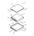
図1は溶着前の電池パックの例を示す分解斜視図である。電池パックは、四角形状の第1底板17及び第1底板17の外周に形成された第1側板16を有する第1ケース半体1と、四角形状の底板26及び底板26の外周に形成された第2側板23を有する第2ケース半体2と、角型の電池3とを備え、第1側板16及び第2側板23の先端部を溶着させた電池ケース(第1ケース半体1及び第2ケース半体2)内に電池3が収納される。
Hereinafter, the present invention will be specifically described with reference to the drawings showing embodiments thereof.
FIG. 1 is an exploded perspective view showing an example of a battery pack before welding. The battery pack is formed on the outer periphery of the first case half 1 having the rectangular
電池3には、電極板4と接続され、外部接続端子4a、及び、過充電及び過放電を防止する保護回路を有する基板5が取付けられている。第2ケース半体2の第2側板23には、電池ケース外部から基板5の外部接続端子4aへ接続を行うための貫通孔4bなどが形成されている。また、第1ケース半体1及び第2ケース半体2は合成樹脂製であり、例えばポリカーボネート及び/又はABS(Acrylonitrile Butadiene Styrene)が用いられている。
A
図1の例では、第2底板26を下側にした第2ケース半体2に電池3を収め、第1底板17を上側にした第1ケース半体1で蓋をし、第1側板16及び第2側板23の先端部を溶着することにより、第1ケース半体1及び第2ケース半体2を一体化した電池ケースに電池3が収納される。
In the example of FIG. 1, the
図2は、電池ケース内側から見た溶着前の第1ケース半体1及び第2ケース半体2の側板先端部の拡大斜視図である。第1ケース半体1の第1側板16先端部には、ケース内面側に内側板13が周設されている。また、前記内側板13の先端部分には、厚さが先細の溶着リブ11が間隔を空けて周設されている。本実施の形態では、第1側板16の厚さaは0.75mmであり、第1側板16先端部のケース内側に形成された内側板13の厚さbは0.35mmであり、先端部の溶着リブ11を含めた内側板13の高さcは0.95mmである。
FIG. 2 is an enlarged perspective view of the front end portions of the side plates of the first case half 1 and the
第2ケース半体2の第2側板23先端部には、溶着リブ11が溶着される溶着面22が形成されている。溶着面22は、第2底板26に対してケース外面側よりもケース内面側が高くなるように傾斜している。また、第2側板23先端部のケース外面側には外側板24が周設されている。よって、第2側板23先端部には、ケース外側に外側板24が形成され、外側板24からケース内側に向かって傾斜した溶着面22が形成されている。本実施の形態では、第2側板23の厚さdは0.75mmであり、第2側板23先端部のケース外側に形成された外側板24の厚さeは0.35mm、高さfは0.40mmである。また、第2底板26に対する溶着面22の傾斜角θは7°である。
A
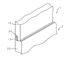
次に超音波溶着時の動作について説明する。図3は溶着後の第1ケース半体1及び第2ケース半体2の側板先端部の拡大斜視図である。第2底板26を下側にした第2ケース半体2に電池3を収め、第1底板17を上側にした第1ケース半体1で蓋をし、第2側板23先端部の溶着面22に、第1側板16先端部の溶着リブ11が接触した状態にする。そして、超音波溶着用治具を第1ケース半体1の所要位置に配置し、所要の高周波を印加することにより、第1ケース半体1に振動が加えられ、溶着リブ11と溶着面22とが振動による摩擦熱により加熱され、溶着リブ11及び溶着面22が溶融する。高周波の印加を終了すると、溶融した部分の温度は徐々に低下し、第1ケース半体1の溶着リブ11と第2ケース半体2の溶着面22とが溶着して一体化される。溶着部分は、外側板24があるため、電池ケース外部からは見えない。
Next, the operation at the time of ultrasonic welding will be described. FIG. 3 is an enlarged perspective view of the end portions of the side plates of the first case half 1 and the
溶着の過程において、溶着面22は、第2底面26に対してケース外側よりもケース内側が高くなるように傾斜しているため、溶着リブ11がケース内側へ移動して溶着面22から落ちる可能性は低い。溶着面22の傾斜により、溶着リブ11のケース内側への移動は抑制されるため、従来の脱落防止リブは不要となる。脱落防止リブが不要となることにより、第2側板23の厚さを薄くすることができる。また、脱落防止リブが不要となることにより、脱落防止リブを設けた際に生じる従来の問題を解決することができる。
In the process of welding, the
上述した実施の形態では、第2底板26に対する溶着面22の傾斜角θを7°としたが、傾斜角θは7°に限定はされない。ただし、傾斜角θが5°よりも小さい場合は、溶着面22の傾斜による溶着リブ11のケース内側への移動に対する抑制力は小さくなり、超音波溶着時に溶着リブ11がケース内側に移動して溶着面22から落ちる可能性がある。また、傾斜角θが10°よりも大きい場合は、溶着リブ11がケース外側へ移動し易くなり、ケース外側の外側板24と内側板13とが接触し、内側板13と外側板24との溶融が起こり、従来の脱落防止リブと側板との溶融と同様な問題が生じる可能性がある。よって、第2底板26に対する溶着面22の傾斜角θは5°から10°にすることが好ましい。
In the embodiment described above, the inclination angle θ of the
また、上述した実施の形態では、溶着面22の第2側板厚さ方向の長さ(=d−e)を0.4mm(=0.75mm−0.35mm)としたが、溶着面22の第2側板厚さ方向の長さは0.4mmに限定はされない。適切な溶着を行うために、溶着面22の第2側板厚さ方向の長さは、溶着リブ11(内側板13)の厚さbの1.0倍以上にすることが好ましい。また、溶着面22の第2側板厚さ方向の長さが、溶着リブ11の厚さbの1.7倍よりも大きければ、溶着面22の厚さ方向の長さは十分広く、脱落防止リブの形成が可能になるが、電池ケースの小型軽量化に反するため、溶着面22の第2側板厚さ方向の長さは、溶着リブ11(内側板13)の厚さbの1.7倍以下にすることが好ましい。例えば溶着リブ11の厚さbが0.3mmの場合、溶着面22の第2側板厚さ方向の長さ(=d−e)は0.3mmから0.5mmにするのが好ましい。
In the above-described embodiment, the length (= de) of the
上述した実施の形態では、第2側板23先端部のケース外側に高さe=0.35mmの外側板24を設け、また、第1側板16先端部のケース内側に高さc=0.95mmの内側板13(先端の溶着リブ11を含む)を設けたが、内側板13(溶着リブ11も含む)及び外側板24の高さは夫々所要の高さにすることが可能である。また、溶着リブ11の形状又は間隔も所要の形状又は間隔にすることが可能である。
In the embodiment described above, the
1 第1ケース半体
2 第2ケース半体
3 電池
16 第1側板
17 第1底板
23 第2側板
26 第2底板
11 溶着リブ
22 溶着面
DESCRIPTION OF SYMBOLS 1
Claims (3)
前記溶着面は、第2底板に対して第2側板外面側よりも第2側板内面側が高くなるように傾斜していることを特徴とする電池パック。 A first case half having a first bottom plate and a first side plate formed on an outer periphery of the first bottom plate, and a protruding welding rib formed at a tip portion of the first side plate; a second bottom plate; A second case half having a second side plate formed on the outer periphery of the bottom plate, and a welding surface on which the welding rib is welded to a tip portion of the second side plate; and the welding rib and the welding surface. In a battery pack comprising the welded first case half and the battery housed in the second case half,
The battery pack is characterized in that the welding surface is inclined with respect to the second bottom plate so that the inner surface side of the second side plate is higher than the outer surface side of the second side plate.
Priority Applications (1)
| Application Number | Priority Date | Filing Date | Title |
|---|---|---|---|
| JP2004020510A JP2005216632A (en) | 2004-01-28 | 2004-01-28 | Battery pack |
Applications Claiming Priority (1)
| Application Number | Priority Date | Filing Date | Title |
|---|---|---|---|
| JP2004020510A JP2005216632A (en) | 2004-01-28 | 2004-01-28 | Battery pack |
Publications (1)
| Publication Number | Publication Date |
|---|---|
| JP2005216632A true JP2005216632A (en) | 2005-08-11 |
Family
ID=34904400
Family Applications (1)
| Application Number | Title | Priority Date | Filing Date |
|---|---|---|---|
| JP2004020510A Pending JP2005216632A (en) | 2004-01-28 | 2004-01-28 | Battery pack |
Country Status (1)
| Country | Link |
|---|---|
| JP (1) | JP2005216632A (en) |
Cited By (4)
| Publication number | Priority date | Publication date | Assignee | Title |
|---|---|---|---|---|
| JP2008192397A (en) * | 2007-02-02 | 2008-08-21 | Sanyo Electric Co Ltd | Battery pack |
| EP2068382A3 (en) * | 2007-12-03 | 2010-02-24 | Byd Company Limited | Battery cover |
| JP2010262757A (en) * | 2009-04-30 | 2010-11-18 | Sanyo Electric Co Ltd | Battery pack |
| WO2011096159A1 (en) * | 2010-02-02 | 2011-08-11 | パナソニック株式会社 | Battery case and battery pack provided therewith |
-
2004
- 2004-01-28 JP JP2004020510A patent/JP2005216632A/en active Pending
Cited By (5)
| Publication number | Priority date | Publication date | Assignee | Title |
|---|---|---|---|---|
| JP2008192397A (en) * | 2007-02-02 | 2008-08-21 | Sanyo Electric Co Ltd | Battery pack |
| EP2068382A3 (en) * | 2007-12-03 | 2010-02-24 | Byd Company Limited | Battery cover |
| JP2010262757A (en) * | 2009-04-30 | 2010-11-18 | Sanyo Electric Co Ltd | Battery pack |
| WO2011096159A1 (en) * | 2010-02-02 | 2011-08-11 | パナソニック株式会社 | Battery case and battery pack provided therewith |
| JPWO2011096159A1 (en) * | 2010-02-02 | 2013-06-10 | パナソニック株式会社 | Battery storage case and battery pack provided with the same |
Similar Documents
| Publication | Publication Date | Title |
|---|---|---|
| JP4972823B2 (en) | Battery pack | |
| JP2015009551A (en) | Sealed casing and production method thereof | |
| JP2009218280A (en) | Semiconductor device | |
| JP2015012065A (en) | Manufacturing method of semiconductor device | |
| JP2010074153A (en) | Method of manufacturing electronic component, electronic component, and jig | |
| CN106486702A (en) | The manufacture method of enclosed-type battery | |
| US20090084589A1 (en) | Lead terminal bonding method and printed circuit board | |
| JP2005216632A (en) | Battery pack | |
| JP2012209174A (en) | Battery back and joining method of separation cases | |
| JP2011076968A (en) | Battery housing case and its joining method | |
| JP2000135740A (en) | Electrical equipment case and its manufacturing method | |
| JP6447266B2 (en) | Manufacturing method of current interrupting device | |
| JP3776907B2 (en) | Circuit board | |
| JP4282470B2 (en) | Battery pack | |
| JP2005116943A (en) | Printed wiring board, mounting board module, printed wiring board manufacturing method, electro-optical device using the same, and electronic apparatus | |
| JP2006120914A (en) | Component suction nozzle, component mounting apparatus, and component mounting method | |
| JP2006086463A (en) | Lid tacking device and tacking electrode | |
| JP4810180B2 (en) | Lithium ion battery pack | |
| JP2006049047A (en) | Battery pack and method of manufacturing battery pack | |
| JP2000123807A (en) | Battery pack | |
| JP2013102344A (en) | Electronic component package | |
| JP2008142738A (en) | Ultrasonic bonding apparatus and control method thereof | |
| JP2006210167A (en) | Coin battery | |
| JP4666945B2 (en) | Pack battery | |
| JP2005317391A (en) | Battery pack and manufacturing method of battery pack |
Legal Events
| Date | Code | Title | Description |
|---|---|---|---|
| A621 | Written request for application examination |
Free format text: JAPANESE INTERMEDIATE CODE: A621 Effective date: 20050721 |
|
| A977 | Report on retrieval |
Free format text: JAPANESE INTERMEDIATE CODE: A971007 Effective date: 20081010 |
|
| A131 | Notification of reasons for refusal |
Free format text: JAPANESE INTERMEDIATE CODE: A131 Effective date: 20081111 |
|
| A02 | Decision of refusal |
Free format text: JAPANESE INTERMEDIATE CODE: A02 Effective date: 20090317 |