JP2005206367A - Bag unloader/loader - Google Patents
Bag unloader/loader Download PDFInfo
- Publication number
- JP2005206367A JP2005206367A JP2004017609A JP2004017609A JP2005206367A JP 2005206367 A JP2005206367 A JP 2005206367A JP 2004017609 A JP2004017609 A JP 2004017609A JP 2004017609 A JP2004017609 A JP 2004017609A JP 2005206367 A JP2005206367 A JP 2005206367A
- Authority
- JP
- Japan
- Prior art keywords
- tray
- bag
- rows
- pin
- pin group
- Prior art date
- Legal status (The legal status is an assumption and is not a legal conclusion. Google has not performed a legal analysis and makes no representation as to the accuracy of the status listed.)
- Pending
Links
Images


Landscapes
- Intermediate Stations On Conveyors (AREA)
- Specific Conveyance Elements (AREA)
Abstract
Description
本発明は、底面に多数の穴が規則的に形成された平面視矩形のトレイから、そこに載置されたレトルトパウチのような袋を取り出すアンローダ、及び前記トレイに袋を装入するローダに関する。 The present invention relates to an unloader for taking out a bag such as a retort pouch mounted thereon from a rectangular tray with a large number of holes regularly formed on the bottom surface, and a loader for loading the bag into the tray. .
下記特許文献1には、底面に多数の穴が規則的に形成されたトレイを所定距離ずつ搬送する搬送手段と、その搬送方向に平行に向く複数のローラと、昇降可能でかつ前記トレイの搬送方向と同方向に往復動可能なピン群からなるピンリフト式移送装置が記載されている。この移送装置を用いて袋が載置されたトレイからその袋を取り出す際は、前記ピン群をトレイの下に位置せしめ、前記ピン群を上昇させ、前記トレイの穴を貫通して上方に突出させ、その先端で袋を前記ローラの位置より高く支持し、続いてピン群とトレイをローラの下方に移動し、ピン群を下降させて袋をローラ上に置き残し、この袋をローラを回転させて搬出する。
In
上記移送装置では、袋をトレイの穴から上方に突出するピン群の先端に載せ、その状態で前記ピン群をトレイの位置からローラの間の位置まで水平移動させるため、次のような問題点がある。
(1)袋のサイズが小さいとピン群による袋の支持が不安定となり、ピン群を水平移動させたとき、袋が位置ずれを起こしたり、ピンの先端から落下するおそれがある。ピン群の水平移動を高速で行うほど、特に前進開始時及び停止時に慣性によって袋が位置ずれを起こしたり、落下しやすくなる。また、内側の仕切り壁がないトレイの場合、トレイ内での袋の向きがトレイの搬送中に乱れるため、一層そのおそれが深刻化する。
(2)ピン群を水平移動させるとき、ピンの数が多くなると移動の慣性重量が大きくなり、移送装置を高速で稼動させることが難しくなる。
(3)ピンがトレイの穴にはまった状態でピン群とトレイを一緒に水平移動させるため、移動中に相対的な位置がずれてピンがトレイの穴の縁を擦り、穴の縁にバリが生じることがあり、このバリにより袋に傷が付くおそれがある。
In the above transfer device, the bag is placed on the tip of the pin group protruding upward from the hole of the tray, and in that state, the pin group is moved horizontally from the position of the tray to the position between the rollers. There is.
(1) If the size of the bag is small, the support of the bag by the pin group becomes unstable, and when the pin group is moved horizontally, the bag may be displaced or may fall from the tip of the pin. The higher the horizontal movement of the pin group, the easier it is for the bag to shift or drop due to inertia, particularly at the start and stop of forward movement. Further, in the case of a tray having no inner partition wall, the direction of the bag in the tray is disturbed during the conveyance of the tray, and the risk becomes more serious.
(2) When moving the pin group horizontally, if the number of pins increases, the inertia weight of the movement increases, and it becomes difficult to operate the transfer device at high speed.
(3) Since the pin group and the tray are moved horizontally together with the pin in the tray hole, the relative position shifts during the movement, and the pin rubs the edge of the hole in the tray. The burrs may damage the bag.
また、上記移送装置では、ピン群で支持した袋をローラにより搬出するようにしているため、次のような問題点がある。
(4)袋の内容物が液状物か又は液状物を多く含む場合、袋Wの剛性がなくなるため、図17に示すように、袋Wの形状がローラRの表面形状になじみ、この状態でローラRを回転させてもスリップを起こし、搬送不良や整列状態の乱れが生じる。これはローラ径を小さくするほど顕著となり、特にレトルトパウチの場合は袋Wの表面に多量の水が付着してスリップしやすいため、その傾向が強くなる。ローラコンベアによる搬送を確実に行うには、ローラ径を大きくしかつローラ間の隙間を小さくすることが有効であるが、そうするとピンPの径が小さくなり、また一つの袋を支持するピンの数も減るため、一層ピン群による袋の支持が不安定となる。
Moreover, in the said transfer apparatus, since the bag supported with the pin group is carried out by a roller, there exists the following problems.
(4) If the contents of the bag are liquid or contain a lot of liquid, the rigidity of the bag W is lost, so that the shape of the bag W conforms to the surface shape of the roller R as shown in FIG. Even if the roller R is rotated, slipping occurs, resulting in poor conveyance and disordered alignment. This becomes more prominent as the roller diameter is reduced. In particular, in the case of a retort pouch, a large amount of water tends to adhere to the surface of the bag W and slip easily. In order to reliably carry the roller conveyor, it is effective to increase the roller diameter and reduce the gap between the rollers, but this reduces the diameter of the pin P, and the number of pins supporting one bag. Therefore, the bag support by the pin group becomes more unstable.
(5)ローラの搬送方向はピン群による袋の搬送方向に垂直になるから、ピン群が進入する領域から完全に袋が搬出された後でなければ、次の袋をローラ上に搬送できない。また、前記搬送装置においては一度に1つの袋をローラ上に搬送しているが、レトルトパウチの場合、通常、トレイには縦横とも複数列の袋が載置されている。従って、一度に1列(又は複数列)の袋を順次ローラ上に搬送することになり、この場合も同様に、前回搬送した袋列がローラ上のピン群が進入する領域から完全に搬出されるまで、次の袋列をローラ上に搬送できない。そのため、いずれの場合も搬送スピードが上げられない。 (5) Since the conveyance direction of the roller is perpendicular to the conveyance direction of the bag by the pin group, the next bag cannot be conveyed onto the roller unless the bag is completely unloaded from the region where the pin group enters. In the transport device, one bag is transported onto a roller at a time, but in the case of a retort pouch, usually, a plurality of rows of bags are placed on the tray both vertically and horizontally. Therefore, one row (or a plurality of rows) of bags is sequentially conveyed onto the rollers at a time, and in this case as well, the previously conveyed bag row is completely unloaded from the region where the pin group on the roller enters. Until the next bag row cannot be transported onto the roller. Therefore, in any case, the conveyance speed cannot be increased.
(6)上記(5)に記載したように、前回搬送した袋列がローラ上のピン群が進入する領域から完全に搬出されるまで、次の袋列をローラ上に搬送できないため、同じ袋列の中では袋の間隔は一定であるが、袋列同士の間隔が開いてしまう。この周期的な間隔の開きを以後解消して等間隔で搬送するのは難しい。一方、レトルトパウチの場合、トレイから搬出した袋は水切り装置に一列で連続的に送られて水切りされ、続いて箱詰め装置に送られて箱詰めされるが、袋同士の間隔が一定周期で開いているため、単位時間当りの処理数を稼ぐには搬送速度を上げる必要があり、その結果、水切り装置の全長を長く設定し、また処理能力の高い箱詰め装置を設置する必要がある。 (6) As described in (5) above, the next bag row cannot be transported onto the roller until the bag row transported last time is completely unloaded from the area where the pin group on the roller enters. In the rows, the spacing between the bags is constant, but the spacing between the rows is increased. It is difficult to eliminate this periodic gap and transport it at regular intervals. On the other hand, in the case of a retort pouch, the bags carried out from the tray are continuously sent to the draining device in a row and drained, and then sent to the boxing device and packed in a box. Therefore, in order to increase the number of treatments per unit time, it is necessary to increase the conveyance speed. As a result, it is necessary to set the total length of the draining device to be long and to install a boxing device having a high processing capacity.
なお、上記移送装置は袋をトレイに装入する際にも利用でき、その場合にも、上記(1)〜(5)に指摘したと同様の問題がある。
本発明は、このような従来のピンリフト式移送装置の問題点に鑑みてなされたもので、ピン先端での袋の支持が不安定となって袋が位置ずれを起こしあるいは落下することを防止し、同時にピンがトレイの穴に擦れて穴の縁にバリができ、これによって袋に傷が付くのを防止することを主たる目的とする。また、コンベアによる袋の搬送不良や整列状態の乱れを抑制すること等を他の目的とする。
In addition, the said transfer apparatus can be utilized also when charging a bag to a tray, and also in this case, there are the same problems as pointed out in the above (1) to (5).
The present invention has been made in view of the problems of such a conventional pin lift type transfer device, and prevents the bag from being displaced or dropped due to unstable support of the bag at the pin tip. At the same time, the main purpose is to prevent the pins from rubbing against the holes in the tray and creating burrs at the edges of the holes, thereby scratching the bag. Another object of the present invention is to suppress poor bag conveyance by the conveyor and disorder in the alignment state.
本発明に係る袋のアンローダは、底面に多数の穴が規則的に形成された平面視矩形のトレイを前方に搬送して所定位置に位置決めするトレイ搬送装置と、前記トレイの搬送経路の下方の所定位置に設置され、前記トレイの搬送方向に沿って並列にかつ互いに所定の間隔を置いて複数列に配置された昇降可能なピン群を有し、前記ピン群により前記トレイの搬送方向に垂直な1列又は複数列の袋を前記トレイ内から上方に取り出す袋取出し装置と、前記袋取出し装置の前方側において前記トレイの搬送経路の上方に設置され、前記トレイの搬送方向に沿って並列にかつ互いに所定の間隔を置いて配置された複数のコンベアベルトを有し、前記ピン群から袋を受け取り前方に搬送する袋受取りコンベアを備え、前記ピン群はその先端に袋を載置可能であり、下降位置においてその先端が前記トレイの下方に位置し、上昇位置において前記トレイの穴を貫通して前記トレイの上方に突出し、前記コンベアベルトは前記トレイの搬送方向に沿って往復移動可能とされ、後方側に移動したとき前記ピン群の列の間に進入することを特徴とする。なお、本発明において、トレイの搬送方向の上流側が後方、下流側が前方である。 An unloader for a bag according to the present invention includes a tray transport device that transports a rectangular tray with a plurality of holes regularly formed on a bottom surface to forward and positions the tray at a predetermined position, and a lower portion of the tray transport path. It has a group of pins that can be moved up and down and arranged in a plurality of rows in parallel along the tray transport direction and at predetermined intervals, and is perpendicular to the tray transport direction by the pin group. A bag take-out device for picking up one or more rows of bags from the tray upward, and installed above the tray transport path on the front side of the bag take-out device, and in parallel along the tray transport direction. And a plurality of conveyor belts arranged at predetermined intervals from each other, including a bag receiving conveyor for receiving bags from the pin group and transporting the bags forward, and the pin group can place a bag on the tip thereof. In the lowered position, the leading end is located below the tray, and in the raised position, it penetrates the hole in the tray and protrudes above the tray. The conveyor belt can reciprocate along the tray conveying direction. And when it moves rearward, it enters between the rows of pins. In the present invention, the upstream side in the tray conveyance direction is the rear side, and the downstream side is the front side.
本発明に係る別のアンローダは、コンベアベルトが往復移動せず、その代わりに、前記袋取出し装置と袋受取りコンベアの間に、前記ピン群から袋を受け取り前記コンベアベルトに引き渡す袋受渡し装置を備える。この袋受渡し装置は前記トレイの搬送経路の上方に設置され、前記トレイの搬送方向に沿って並列にかつ互いに所定の間隔を置いて配置された複数の載置部材を有し、この載置部材は前記トレイの搬送方向に沿って往復移動可能かつ昇降可能とされその上面に袋を載置可能であり、後方側に移動したとき前記ピン群の列の間に進入し、前方側に移動したとき前記コンベアベルトの間に進入するようになっている。 Another unloader according to the present invention includes a bag delivery device that receives a bag from the pin group and delivers it to the conveyor belt between the bag take-out device and the bag receiving conveyor instead of the reciprocating movement of the conveyor belt. . This bag delivery device has a plurality of mounting members that are installed above the tray transport path and are arranged in parallel along the transport direction of the tray and at a predetermined interval from each other. Is capable of reciprocating and elevating along the tray conveying direction, and a bag can be placed on the upper surface thereof. When moved rearward, it entered between the rows of the pin groups and moved forward. Sometimes it enters between the conveyor belts.
本発明に係るローダは、底面に多数の穴が規則的に形成された平面視矩形のトレイを前方に搬送して所定位置に位置決めするトレイ搬送装置と、前記トレイの搬送経路の下方の所定位置に設置され、前記トレイの搬送方向に沿って並列にかつ互いに所定の間隔を置いて複数列に配置された昇降可能なピン群を有し、前記ピン群により前記トレイの搬送方向に垂直な1列又は複数列の袋を上方から前記トレイ内に装入する袋装入装置と、前記袋装入装置の後方側において前記トレイの搬送経路の上方に配置され、前記トレイの搬送方向に沿って並列にかつ互いに所定の間隔を置いて配置された複数のコンベアベルトを有し、袋を前方に搬送して前記ピン群に供給する袋供給コンベアを備え、前記ピン群はその先端に袋を載置可能であり、下降位置においてその先端が前記トレイの下方に位置し、上昇位置において前記トレイの穴を貫通して前記トレイの上方に突出し、前記コンベアベルトは前記トレイの搬送方向に沿って往復移動可能とされ、前方側に移動したとき前記ピン群の列の間の位置に進入することを特徴とする。 A loader according to the present invention includes a tray transport device that transports a rectangular tray in plan view, in which a large number of holes are regularly formed on the bottom surface, and positions the tray in a predetermined position, and a predetermined position below the tray transport path. And a group of pins that can be moved up and down in parallel along the transport direction of the tray and arranged in a plurality of rows at predetermined intervals, and is perpendicular to the transport direction of the tray by the pin group. A bag loading device for loading a row or a plurality of rows of bags into the tray from above, and a rear side of the bag loading device, disposed above the tray conveyance path, along the tray conveyance direction. It has a plurality of conveyor belts arranged in parallel and spaced apart from each other, and includes a bag supply conveyor that conveys the bags forward and supplies them to the pin group, and the pin group carries a bag at its tip. Can be placed, descending position The front end of the conveyor belt is located below the tray, protrudes upward from the tray through the hole in the tray at the raised position, and the conveyor belt is capable of reciprocating along the transport direction of the tray. It moves to the position between the rows of the pin group when moved to.
本発明に係る別のローダは、コンベアベルトが往復移動せず、その代わりに、前記袋装入装置と袋供給コンベアの間に、前記コンベアベルトから袋を受け取り前記ピン群に引き渡す袋受渡し装置を備える。この袋受渡し装置は前記トレイの搬送経路の上方に設置され、前記トレイの搬送方向に沿って並列にかつ互いに所定の間隔を置いて配置された複数の載置部材を有し、この載置部材は、前記トレイの搬送方向に沿って往復移動可能かつ昇降可能とされその上面に袋を載置可能であり、前方側に移動したとき前記ピン群の列の間の位置に進入し、後方側に移動したとき前記コンベアベルトの間に進入するようになっている。 In another loader according to the present invention, a conveyor belt does not reciprocate. Instead, a bag delivery device that receives a bag from the conveyor belt and delivers it to the pin group between the bag charging device and a bag supply conveyor is provided. Prepare. This bag delivery device has a plurality of mounting members that are installed above the tray transport path and are arranged in parallel along the transport direction of the tray and at a predetermined interval from each other. Is capable of reciprocating along the transport direction of the tray and can be moved up and down, and a bag can be placed on the upper surface thereof. When moved forward, it enters a position between the rows of the pins, and the rear side When it moves to, it will enter between the said conveyor belts.
前記アンローダ又はローダにおいて、載置部材の上面(袋の支持面)に袋をより安定的に支持するため、該載置部材の上面に袋吸着用の吸着穴を形成し、かつ前記吸着穴に真空源を接続させることができる。また、ピンの先端(袋の支持面)に袋をより安定的に支持するため、該ピンの先端に袋吸着用の吸着穴を形成し、かつ前記吸着穴に真空源を接続させることができる。
さらに、前記アンローダ又はローダにおいて、ピンの先端に袋をより安定的に支持するため、前記ピン群の上に袋押さえ部材を昇降自在に配置することができる。アンローダにおいては、前記袋押さえ部材は前記ピン群の上昇に合わせて上昇するようにし、ローダにおいては、前記ピン群の下降に合わせて下降するようにする。
In the unloader or loader, in order to more stably support the bag on the upper surface of the placement member (bag support surface), a suction hole for sucking the bag is formed on the upper surface of the placement member, and the suction hole A vacuum source can be connected. Further, in order to more stably support the bag on the tip of the pin (bag support surface), a suction hole for sucking the bag can be formed at the tip of the pin, and a vacuum source can be connected to the suction hole. .
Furthermore, in the unloader or loader, in order to more stably support the bag at the tip of the pin, a bag pressing member can be arranged on the pin group so as to be movable up and down. In the unloader, the bag holding member is raised as the pin group is raised, and in the loader, the bag holding member is lowered as the pin group is lowered.
なお、上記アンローダ及びローダにおいて、前記トレイに形成された穴はトレイの搬送方向に沿って長いスリット状の穴を含み、またピンは前記スリット状の穴を貫通する板状のピンを含む。スリット状の穴及び板状のピンは前記特許文献1にも記載されている。
また、上記アンローダ又はローダにおいて、前記トレイ搬送装置の上流側に前記トレイ(アンローダの場合袋が載置された実トレイ、ローダの場合空トレイ)を前記トレイ搬送装置の所定位置に供給するトレイ供給装置を設置し、前記トレイ搬送装置の下流側に前記トレイ(アンローダの場合空トレイ、ローダの場合実トレイ)を取り出すトレイ取出装置を設置することができる。
In the unloader and loader, the hole formed in the tray includes a slit-like hole that is long along the tray transport direction, and the pin includes a plate-like pin that penetrates the slit-like hole. The slit-like hole and the plate-like pin are also described in
Also, in the unloader or loader, a tray supply for supplying the tray (a real tray on which a bag is placed in the case of an unloader or an empty tray in the case of a loader) to a predetermined position of the tray transporter in the upstream side of the tray transporter. An apparatus can be installed, and a tray take-out apparatus for taking out the tray (an empty tray in the case of an unloader and an actual tray in the case of a loader) can be installed on the downstream side of the tray conveying apparatus.
本発明に係るアンローダ及びローダによれば、袋取出し装置又は袋装入装置において、ピン群は昇降のみで水平方向に移動しないから、これらが水平移動する場合(従来例)に比べて袋の支持が安定し、袋が位置ずれを起こしたり、ピンの先端から落下するのが防止できる。また、ピン群を水平移動させる必要がないため、ピンの数を増やして支持をより安定させることも容易である。さらに、ピンは定位置において昇降するのみであるので、従来のように水平移動中にトレイとの間に相対的な位置ずれが起き、ピンがトレイの穴の縁を擦ってバリを形成することも抑えられ、そのバリにより袋が傷つくことが防止される。 According to the unloader and the loader according to the present invention, in the bag take-out device or the bag loading device, the pin group does not move in the horizontal direction only by raising and lowering, and therefore, the bag support compared to the case where these move horizontally (conventional example). It is possible to prevent the bag from being displaced or falling from the tip of the pin. In addition, since it is not necessary to move the pin group horizontally, it is easy to increase the number of pins to make the support more stable. In addition, since the pins only move up and down at a fixed position, a relative positional deviation occurs with the tray during horizontal movement as in the past, and the pins rub against the edges of the holes in the tray to form burrs. The burr prevents the bag from being damaged.
本発明に係るアンローダ及びローダによれば、袋受取りコンベア又は袋供給コンベアがいずれも所定の間隔を置いて並列に配置した複数のコンベアベルトを有し、あるいは袋受渡し装置が所定の間隔を置いて並列に配置した複数の載置部材を有し、これらを移動させて、定位置で昇降するピン群から袋を受け取り又はピン群に袋を供給するようにしたから、袋の前後方向への移動が安定して行われる。これは、袋は移動中において上記コンベアベルト又は載置部材に面接触した状態であり、従来(移動中の接触はピン先端との点接触又はローラとの線接触)に比べて接触面積をはるかに大きくとることができるからである。そして、これにより、装置全体を高速で動かすことが可能となる。
なお、ピンの先端や載置部材の上面に吸着穴を形成し減圧して袋を吸着したり、ピン群の上に袋押さえ部材を設けることにより、袋の支持がさらに安定する。袋の支持が安定すれば、ピンの数や載置部材の本数を減らすことも可能となる。また、載置部材の移動時のスピードアップも可能となる。
According to the unloader and loader according to the present invention, each of the bag receiving conveyor and the bag supply conveyor has a plurality of conveyor belts arranged in parallel at a predetermined interval, or the bag delivery device has a predetermined interval. Since there are a plurality of mounting members arranged in parallel and these are moved to receive the bag from the pin group that moves up and down at a fixed position or to supply the bag to the pin group, the bag moves in the front-rear direction. Is performed stably. This is a state in which the bag is in surface contact with the conveyor belt or the mounting member during movement, and the contact area is much larger than conventional (contact during movement is point contact with the pin tip or line contact with the roller). This is because it can be greatly increased. As a result, the entire apparatus can be moved at high speed.
The support of the bag is further stabilized by forming a suction hole at the tip of the pin or the upper surface of the mounting member and reducing the pressure to suck the bag, or by providing a bag pressing member on the pin group. If the support of the bag is stable, the number of pins and the number of mounting members can be reduced. Moreover, the speed at the time of movement of a mounting member is also attained.
本発明に係るアンローダ及びローダによれば、トレイと袋の搬送方向が同じ方向であることから、搬送サイクルのスピードを向上させることが可能となる。すなわち、ベルトコンベア上の袋がピン群の間に進入する領域内にまだ存在している段階で、該ベルトコンベアをピン群の間に進入開始させることができ、あるいは、載置部材をベルトコンベアの間に進入開始させることができ、その分だけ、搬送サイクルのスピードアップが可能となる。そして、ベルトコンベアの移動速度と搬送速度及びピン群の昇降のタイミング等を調整することにより、袋を等間隔で搬出することも可能となる。 According to the unloader and loader according to the present invention, the transport direction of the tray and the bag is the same direction, so that the speed of the transport cycle can be improved. That is, when the bag on the belt conveyor is still in the region where the bag enters between the pin groups, the belt conveyor can be started to enter between the pin groups, or the placing member can be moved to the belt conveyor. The entry can be started during this period, and the speed of the transfer cycle can be increased accordingly. And it is also possible to carry out the bag at equal intervals by adjusting the moving speed and conveying speed of the belt conveyor, the timing of raising and lowering the pin group, and the like.
以下、図1〜16を参照して、本発明に係る袋のアンローダ及びローダについて説明する。
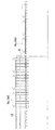
まず、使用するトレイ1は、図9に示すように、前壁2、後壁3、側壁4(一方の側壁は図示せず)及び底壁5からなる矩形のトレイで、底壁5上に、袋(レトルトパウチ)Wが縦横6個ずつ計36個整列して載置されている(前後方向に並んだ袋列が6列あり、それに垂直方向に並んだ袋列Wsが同じく6列ある)。底壁5全体に多数の穴6が碁盤目状に形成されている。なお、実トレイと空トレイを特に区別する場合、実トレイ1a、空トレイ1bとする。
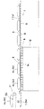
図1〜図9に示すアンローダは、トレイ1を1ピッチ(トレイ1のほぼ半分の長さ)ずつ、前方(図1において左方向)に搬送し、所定位置に位置決めするトレイ搬送装置7(搬送用ローラ8のみ図示)と、トレイ1の搬送経路の下方に設置され、トレイ1の搬送方向(前後方向)に沿って並列にかつ互いに所定の間隔を置いて複数列(この例では29列、各列に18個ずつ)に配置された昇降可能なピン群9を有する袋取出し装置10と、袋取出し装置10の前方側においてトレイ1の搬送経路の上方に設置された袋受取りコンベア11(後端側のコンベアベルト12のみ図示)からなる。
The bag unloader and loader according to the present invention will be described below with reference to FIGS.
First, the
The unloader shown in FIGS. 1 to 9 transports the
袋取出し装置10において、ピン群9を構成する各ピン9aは所定位置に位置決めされたトレイ1の穴6の位置にちょうど対応して配置され、穴6より小径とされ、ピン群9の先端には袋Wを載置可能である。ピン群9は昇降可能であり、下降位置においてその先端(ピン9aの先端)がトレイ1の下方に位置し、上昇位置においてトレイ1の穴6を貫通してトレイ1の上方に突出し、このとき、トレイ1内に載置された6つの袋列Ws(トレイの搬送方向に対して垂直方向に並んだ袋列)のうち、1ピッチ分の範囲内にある袋列(この例では3列)の袋Wを、トレイ1の上方に一度に取り出すことができる。
袋受取りコンベア11は、その後端側において、トレイ1の搬送方向に沿って並列にかつ互いに所定の間隔を置いて配置された多数のコンベアベルト12を有する。従って、袋受取りコンベア11の後端部は、図9に示すように、櫛歯状となっていて、隣接するコンベアベルト12の間隔はピン9aの直径より広く、コンベアベルト12の幅はピン群9の隣接する列の間隔より小さく設定されている。そして、袋受取りコンベア11は(コンベアベルト12も同時に)、トレイ1の搬送方向に沿って水平面内で往復移動可能とされ、袋受取りコンベア11が後方側に移動したときコンベアベルト12がピン群9の列の間に進入する。このときのコンベアベルト12の上端位置(搬送面12aの位置)は、上昇位置にあるピン群9の先端の位置より下方に位置する。その進入長さはトレイ1の搬送距離のほぼ1ピッチ分であり、ピン群9を構成する列の前後方向長さ(トレイ1の搬送方向にみたピン群9の長さ)にほぼ相当する。なお、袋受取りコンベア11は全体として往復移動可能でなく、例えば特開平9−272626号公報に記載されたスライドコンベアのように、後端部分のみが往復移動可能であってもよい。また、全体が櫛歯状に配置されたベルトコンベア12から構成されていなくても、少なくとも後端部がベルトコンベア12により櫛歯状に形成されていればよい。
In the bag take-out
The
図1〜図8を参照して、このアンローダの作動及び作用について工程順に説明する。
(1)図1に示すように、トレイ搬送装置7により実トレイ1aが前方に送り出され、所定位置で停止し、位置決めされる。このとき、ピン群9は下降しており、その先端は実トレイ1aの底壁5より下方に位置する。従って、ピン群9と実トレイ1aは互いに干渉しない。また、位置決めされた実トレイ1aの各穴6は、ピン群9の各ピン9aの直上に位置する。この時点では、コンベアベルト12上に、前の空トレイ1bから取り出された袋列Wsが存在する。
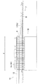
(2)図2に示すように、ピン群9が上昇し、実トレイ1aの穴6を貫通してトレイ1の上方に突出し、トレイ1内の1ピッチ分の範囲内にある袋列Wsを上方に取り出す。突出したピン群9の先端位置(取り出された袋Wの下端位置)は、コンベアベルト12の上端位置(搬送面12aの位置)より余裕をもって高い。
With reference to FIGS. 1-8, the action | operation and effect | action of this unloader are demonstrated in order of a process.
(1) As shown in FIG. 1, the
(2) As shown in FIG. 2, the
(3)図3に示すように、コンベアベルト12が後方側に水平移動してピン群9の列の間に進入し、ピン群9によりトレイ1の上方に持ち上げられた1ピッチ分の袋列Wsの下方位置に停止する。この例のように、ベルトコンベア12が前回受け取った袋列Wsが、ピン群9の間に進入する領域(図3にdで示す)の外、つまり該領域の前方側に全て搬送されてから、ベルトコンベア12をピン群9の間に進入開始させることもできるが、前記領域内に前回の袋列Wsがまだ存在している段階で進入開始することもできる。その場合、搬送のサイクルのスピードアップが可能となるが、ベルトコンベア12上の袋列Wsがピン群9と干渉しないようなタイミングに設定する必要がある。
(4)図4に示すように、ピン群9が下降し、ピン群9の先端に支持されていた袋列Wsはコンベアベルト12上に置き残される。
(5)図5に示すように、トレイ搬送装置7により実トレイ1aが1ピッチ前方に送り出され、所定位置で停止し、一方、コンベアベルト12は前方側に移動し、停止する。なお、この例では、ピン群9からコンベアベルト12への袋列Wsの移し替えが行われるときから(図4参照)、コンベアベルト12が前方側に移動するまでの間、該コンベアベルト12の回転は停止しているが、その間に回転を続けていてもよいし、あるいは例えば移し替えが行われると同時に回転を始めてもよい。
(6)図6〜図8に示すように、次の1ピッチ分の範囲内の袋列Wsに対して同様の工程が繰り返される。
(3) As shown in FIG. 3, the
(4) As shown in FIG. 4, the
(5) As shown in FIG. 5, the
(6) As shown in FIGS. 6-8, the same process is repeated with respect to the bag row Ws within the range of the next one pitch.
詳細な説明は省略するが、図1〜図9に示すアンローダは、逆に作動させることにより、ローダとして機能させることができる。 Although a detailed description is omitted, the unloader shown in FIGS. 1 to 9 can function as a loader by operating in reverse.
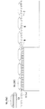
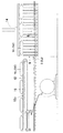
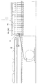
図10〜図16に別のアンローダを示す。このアンローダは、図1〜図9に示すアンローダとは、袋受取りコンベア11が(コンベアベルト12も)往復移動しない点、トレイ1の搬送経路の上方に設置され、ピン群9から袋Wを受け取りコンベアベルト12に引き渡す袋受渡し装置13を備える点、及びピン群9の上に昇降自在に配置された袋押さえ部材14を備える点で異なるが、その他の点では変わるところはない。
袋受渡し装置13は、トレイ1の搬送方向に沿って並列にかつ互いに所定の間隔を置いて配置された多数の載置部材15を有する。載置部材15はトレイ1の搬送方向に沿って往復移動可能かつ昇降可能とされ、ピン群9により持ち上げられた1ピッチ分の袋列Wsをその上面に載置可能であり、図16に示すように櫛歯状に配列していて、後方側に移動したときピン群9の列の間に進入し、前方側に移動したときコンベアベルト12の列の間に進入する。各載置部材15の幅は、隣接するコンベアベルト12の間隔より小さく、かつピン群9の隣接する列の間隔より小さく設定され、その前後方向長さはトレイ1の搬送距離のほぼ1ピッチ分であり、ピン群9を構成する列の前後方向長さ(トレイ1の搬送方向にみたピン群9の長さ)にほぼ相当する。
10 to 16 show another unloader. 1 to 9, the unloader shown in FIGS. 1 to 9 is installed above the conveying path of the
The
載置部材15の前端にはそれぞれリンク連結部16が固定され、各リンク連結部16にはそれぞれリンク17,18の後端がピン連結され、リンク17,18の前端が共通の連結プレート19上に固定されたリンク連結部21にピン連結され、ここに平行リンク機構が形成されている。平行リンク機構のうちリンク連結部16,21及びリンク17,18は、コンベアベルト12の列の間に位置している。
連結プレート19はコンベアベルト12の下方位置にあって、図示しない支持手段によりトレイ1の搬送方向に沿って往復移動可能に支持され、かつ図示しない駆動源により水平面内で往復移動し、これにより載置部材15がトレイ1の搬送方向に沿って往復移動する。また、全てのリンク18について、その前端が共通のピン22(軸方向に延びている)に固定され、該ピン22は図示しない駆動源により回動可能とされ、これにより平行リンク機構が作動し、載置部材15が昇降する。
また、載置部材15の上面は平らで、袋吸着用の吸着穴23が長さ方向に沿って多数形成され、各吸着穴23は共通の真空配管24を介して真空源(ブロアー)25に常時接続している。
袋押さえ部材14は、その全面に弾性部材26が貼り付けられ、ピン群9により持ち上げられた1ピッチ分の袋列Wsをその下面で押さえることができる。
The connecting
The upper surface of the mounting
The
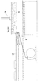
図10〜図15を参照して、このアンローダの作動及び作用について工程順に説明する。
(1)図10に示すように、トレイ搬送装置7により実トレイ1aが前方に送り出され、所定位置で停止し、位置決めされる。続いて袋押さえ部材14が下降し、トレイ1内の1ピッチ分の範囲内にある袋列Wsを上から押さえる。一方、載置部材15は前方側において上昇位置にあり、かつコンベアベルト12の間に位置している。その上には前の空トレイ1bから取り出された袋列Wsが存在し、各袋Wは吸着穴23を通して吸着されているので、載置部材15上に安定して支持されている。
With reference to FIGS. 10 to 15, the operation and action of the unloader will be described in the order of steps.
(1) As shown in FIG. 10, the
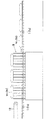
(2)図11に示すように、ピン群9が上昇し、実トレイ1aの穴6を貫通してトレイ1の上方に突出し、トレイ1内の1ピッチ分の範囲内にある袋列Wsを上方に取り出す。ピン群9の上昇に合わせて袋押さえ部材14が上昇し、袋列Wsは袋押さえ部材14により挟まれた状態で安定して持ち上げられる。一方、載置部材15はコンベアベルト12の間を下降し、コンベアベルト12上に袋列Wsを置き残す。吸着穴23による吸着力は余り大きく設定していない(する必要がない)ので、このとき袋Wは載置部材15から簡単に離れる。載置部材15が下降位置にあるとき、その上面はコンベアベルト12の上端位置(搬送面12aの位置)及び突出したピン群9の先端位置(取り出された袋Wの下端位置)より余裕を持って低い。
なお、この例では、載置部材15からコンベアベルト12への袋列Wsの引き渡しが行われるとき、該コンベアベルト12の回転は停止しているが、その間に回転を続けていてもよい。
(2) As shown in FIG. 11, the
In this example, when the bag row Ws is transferred from the placing
(3)図12に示すように、載置部材15が後方側に水平移動し、ピン群9の列の間に進入し、ピン群9によりトレイ1の上方に持ち上げられた1ピッチ分の袋列Wsの下方位置に停止する。
(4)図13に示すように、載置部材15が上昇し、同時に袋押さえ部材14が上昇し、続いてピン群9が下降し、ピン群9の先端に支持されていた袋列Wsは載置部材15上に置き残される。このとき、袋Wは吸着穴23を通して吸着され、載置部材15上に安定して支持される。
(5)図14に示すように、載置部材15は上昇位置のまま前方側に移動し、コンベアベルト12の間に進入する。袋Wは吸着穴23を通して吸着されているので、この移動の間、袋Wは載置部材15上に安定して支持されている。一方、トレイ搬送装置7により実トレイ1aが前方に送り出され、所定位置で停止して位置決めされ、続いて袋押さえ部材14が下降し、トレイ1内の残りの1ピッチ分の範囲内の袋列Wsを上から押さえる。
(6)以後、図15に示すように、同様の工程が繰り返される。
(3) As shown in FIG. 12, the
(4) As shown in FIG. 13, the mounting
(5) As shown in FIG. 14, the placing
(6) Thereafter, the same steps are repeated as shown in FIG.
詳細な説明は省略するが、図10〜図16に示すアンローダは、逆に作動させることにより、ローダとして機能させることができる。
なお、上記の例ではピン9の先端に吸着穴を設けていないが、ピン9の先端に吸着穴を設けて、それを真空源に接続すれば、ピン群9による袋Wの昇降がより安定して行える。ピンの先端に吸着穴を設けて、それを真空源に接続することによるこの作用効果は、前記特許文献1の装置においても同様に奏される。
また、上記の例では、袋押さえ部材14はピン群9の上で昇降のみするようになっていたが、さらにトレイの搬送方向に沿って往復移動可能とし、コンベアベルト12の前方への移動に追随して(図1〜図9の例)、又は載置部材15の前方への移動に追随して(図10〜図16の例)、前方へ移動させることもできる。
Although detailed description is omitted, the unloader shown in FIGS. 10 to 16 can function as a loader by operating in reverse.
In the above example, the suction hole is not provided at the tip of the
In the above example, the
1 トレイ
6 トレイの穴
7 トレイ搬送装置
9 ピン群
10 袋取出し装置
11 袋受取りコンベア
12 コンベアベルト
13 袋受渡し装置
14 袋押さえ部材
15 載置部材
23 吸着穴
W 袋
Ws 袋列(トレイの搬送方向に対し垂直な列)
DESCRIPTION OF
W bag Ws bag row (row perpendicular to the tray transport direction)
Claims (8)
Priority Applications (1)
| Application Number | Priority Date | Filing Date | Title |
|---|---|---|---|
| JP2004017609A JP2005206367A (en) | 2004-01-26 | 2004-01-26 | Bag unloader/loader |
Applications Claiming Priority (1)
| Application Number | Priority Date | Filing Date | Title |
|---|---|---|---|
| JP2004017609A JP2005206367A (en) | 2004-01-26 | 2004-01-26 | Bag unloader/loader |
Publications (2)
| Publication Number | Publication Date |
|---|---|
| JP2005206367A true JP2005206367A (en) | 2005-08-04 |
| JP2005206367A5 JP2005206367A5 (en) | 2006-09-28 |
Family
ID=34902373
Family Applications (1)
| Application Number | Title | Priority Date | Filing Date |
|---|---|---|---|
| JP2004017609A Pending JP2005206367A (en) | 2004-01-26 | 2004-01-26 | Bag unloader/loader |
Country Status (1)
| Country | Link |
|---|---|
| JP (1) | JP2005206367A (en) |
Cited By (4)
| Publication number | Priority date | Publication date | Assignee | Title |
|---|---|---|---|---|
| CN102367076A (en) * | 2011-10-02 | 2012-03-07 | 上海宏曲电子科技有限公司 | Hanging parallel-pushing queuing device of tubular material package |
| JP2013227122A (en) * | 2012-04-25 | 2013-11-07 | Shibuya Kogyo Co Ltd | Article carrying device |
| ES2553306R1 (en) * | 2014-06-04 | 2016-03-10 | Metronics Technologies, S.L. | SYSTEM FOR LOADING AND UNLOADING PRODUCTS IN TRAYS OF CUTTING MACHINES BY WATER JET |
| KR20230060981A (en) * | 2021-10-28 | 2023-05-08 | 주식회사 에스에프에이 | Transfer and separation system for a tray |
-
2004
- 2004-01-26 JP JP2004017609A patent/JP2005206367A/en active Pending
Cited By (6)
| Publication number | Priority date | Publication date | Assignee | Title |
|---|---|---|---|---|
| CN102367076A (en) * | 2011-10-02 | 2012-03-07 | 上海宏曲电子科技有限公司 | Hanging parallel-pushing queuing device of tubular material package |
| WO2013049978A1 (en) * | 2011-10-02 | 2013-04-11 | 上海宏曲电子科技有限公司 | Hanging parallel-push type queuing device for packaging by tubular material |
| JP2013227122A (en) * | 2012-04-25 | 2013-11-07 | Shibuya Kogyo Co Ltd | Article carrying device |
| ES2553306R1 (en) * | 2014-06-04 | 2016-03-10 | Metronics Technologies, S.L. | SYSTEM FOR LOADING AND UNLOADING PRODUCTS IN TRAYS OF CUTTING MACHINES BY WATER JET |
| KR20230060981A (en) * | 2021-10-28 | 2023-05-08 | 주식회사 에스에프에이 | Transfer and separation system for a tray |
| KR102630002B1 (en) * | 2021-10-28 | 2024-01-29 | 주식회사 에스에프에이 | Transfer and separation system for a tray |
Similar Documents
| Publication | Publication Date | Title |
|---|---|---|
| JP6439312B2 (en) | Article transfer device | |
| JP5855365B2 (en) | Apparatus and method for stacking packaging units | |
| CN106184878B (en) | Ceramic tile automated packaging equipment | |
| JP6109509B2 (en) | Article alignment supply device | |
| JP2005206367A (en) | Bag unloader/loader | |
| JP2007217020A (en) | Automatic commercial product stacking method and machine therefor | |
| JP2005206367A5 (en) | ||
| JP2003020117A (en) | Arrangement controller for agricultural products and box packing device therewith | |
| JP4014235B2 (en) | Container alignment device | |
| JP7273290B2 (en) | Stacking device for bags | |
| JP2006213459A (en) | Take-out device for sheet-like article | |
| JP5392625B2 (en) | Loading guide mounting device and mounting method | |
| JP2021102448A (en) | Article accumulation transfer device | |
| JP2009035310A (en) | Goods transfer apparatus | |
| US8052371B2 (en) | Bag supply apparatus | |
| JP2008156075A (en) | Paper feed device | |
| JP2515116Y2 (en) | Transport equipment for crop selection | |
| JP2011026041A (en) | Article stacking supply device | |
| JP3376473B2 (en) | Article transfer device | |
| JP7285006B2 (en) | Product accumulation supply device | |
| JP7302586B2 (en) | Goods storage facility | |
| CN111063644B (en) | Discharging device for semiconductor processing equipment and semiconductor processing equipment | |
| JP7105676B2 (en) | Goods transport system | |
| JP7055298B2 (en) | Goods supply system | |
| JP3691232B2 (en) | Agricultural product transport and supply equipment |
Legal Events
| Date | Code | Title | Description |
|---|---|---|---|
| A521 | Written amendment |
Effective date: 20060807 Free format text: JAPANESE INTERMEDIATE CODE: A523 |
|
| A621 | Written request for application examination |
Free format text: JAPANESE INTERMEDIATE CODE: A621 Effective date: 20060807 |
|
| A977 | Report on retrieval |
Effective date: 20090203 Free format text: JAPANESE INTERMEDIATE CODE: A971007 |
|
| A131 | Notification of reasons for refusal |
Free format text: JAPANESE INTERMEDIATE CODE: A131 Effective date: 20090217 |
|
| A02 | Decision of refusal |
Effective date: 20090707 Free format text: JAPANESE INTERMEDIATE CODE: A02 |