JP2005201456A - Assembling method of rolling bearing unit for supporting wheel - Google Patents
Assembling method of rolling bearing unit for supporting wheel Download PDFInfo
- Publication number
- JP2005201456A JP2005201456A JP2005069740A JP2005069740A JP2005201456A JP 2005201456 A JP2005201456 A JP 2005201456A JP 2005069740 A JP2005069740 A JP 2005069740A JP 2005069740 A JP2005069740 A JP 2005069740A JP 2005201456 A JP2005201456 A JP 2005201456A
- Authority
- JP
- Japan
- Prior art keywords
- preload
- bearing
- caulking
- inner ring
- tightening
- Prior art date
- Legal status (The legal status is an assumption and is not a legal conclusion. Google has not performed a legal analysis and makes no representation as to the accuracy of the status listed.)
- Pending
Links
Images


Classifications
-
- F—MECHANICAL ENGINEERING; LIGHTING; HEATING; WEAPONS; BLASTING
- F16—ENGINEERING ELEMENTS AND UNITS; GENERAL MEASURES FOR PRODUCING AND MAINTAINING EFFECTIVE FUNCTIONING OF MACHINES OR INSTALLATIONS; THERMAL INSULATION IN GENERAL
- F16C—SHAFTS; FLEXIBLE SHAFTS; ELEMENTS OR CRANKSHAFT MECHANISMS; ROTARY BODIES OTHER THAN GEARING ELEMENTS; BEARINGS
- F16C43/00—Assembling bearings
- F16C43/04—Assembling rolling-contact bearings
-
- B—PERFORMING OPERATIONS; TRANSPORTING
- B21—MECHANICAL METAL-WORKING WITHOUT ESSENTIALLY REMOVING MATERIAL; PUNCHING METAL
- B21J—FORGING; HAMMERING; PRESSING METAL; RIVETING; FORGE FURNACES
- B21J9/00—Forging presses
- B21J9/02—Special design or construction
- B21J9/025—Special design or construction with rolling or wobbling dies
-
- B—PERFORMING OPERATIONS; TRANSPORTING
- B21—MECHANICAL METAL-WORKING WITHOUT ESSENTIALLY REMOVING MATERIAL; PUNCHING METAL
- B21K—MAKING FORGED OR PRESSED METAL PRODUCTS, e.g. HORSE-SHOES, RIVETS, BOLTS OR WHEELS
- B21K25/00—Uniting components to form integral members, e.g. turbine wheels and shafts, caulks with inserts, with or without shaping of the components
-
- F—MECHANICAL ENGINEERING; LIGHTING; HEATING; WEAPONS; BLASTING
- F16—ENGINEERING ELEMENTS AND UNITS; GENERAL MEASURES FOR PRODUCING AND MAINTAINING EFFECTIVE FUNCTIONING OF MACHINES OR INSTALLATIONS; THERMAL INSULATION IN GENERAL
- F16C—SHAFTS; FLEXIBLE SHAFTS; ELEMENTS OR CRANKSHAFT MECHANISMS; ROTARY BODIES OTHER THAN GEARING ELEMENTS; BEARINGS
- F16C19/00—Bearings with rolling contact, for exclusively rotary movement
- F16C19/02—Bearings with rolling contact, for exclusively rotary movement with bearing balls essentially of the same size in one or more circular rows
- F16C19/14—Bearings with rolling contact, for exclusively rotary movement with bearing balls essentially of the same size in one or more circular rows for both radial and axial load
- F16C19/18—Bearings with rolling contact, for exclusively rotary movement with bearing balls essentially of the same size in one or more circular rows for both radial and axial load with two or more rows of balls
- F16C19/181—Bearings with rolling contact, for exclusively rotary movement with bearing balls essentially of the same size in one or more circular rows for both radial and axial load with two or more rows of balls with angular contact
- F16C19/183—Bearings with rolling contact, for exclusively rotary movement with bearing balls essentially of the same size in one or more circular rows for both radial and axial load with two or more rows of balls with angular contact with two rows at opposite angles
- F16C19/184—Bearings with rolling contact, for exclusively rotary movement with bearing balls essentially of the same size in one or more circular rows for both radial and axial load with two or more rows of balls with angular contact with two rows at opposite angles in O-arrangement
- F16C19/186—Bearings with rolling contact, for exclusively rotary movement with bearing balls essentially of the same size in one or more circular rows for both radial and axial load with two or more rows of balls with angular contact with two rows at opposite angles in O-arrangement with three raceways provided integrally on parts other than race rings, e.g. third generation hubs
-
- F—MECHANICAL ENGINEERING; LIGHTING; HEATING; WEAPONS; BLASTING
- F16—ENGINEERING ELEMENTS AND UNITS; GENERAL MEASURES FOR PRODUCING AND MAINTAINING EFFECTIVE FUNCTIONING OF MACHINES OR INSTALLATIONS; THERMAL INSULATION IN GENERAL
- F16C—SHAFTS; FLEXIBLE SHAFTS; ELEMENTS OR CRANKSHAFT MECHANISMS; ROTARY BODIES OTHER THAN GEARING ELEMENTS; BEARINGS
- F16C2229/00—Setting preload
-
- F—MECHANICAL ENGINEERING; LIGHTING; HEATING; WEAPONS; BLASTING
- F16—ENGINEERING ELEMENTS AND UNITS; GENERAL MEASURES FOR PRODUCING AND MAINTAINING EFFECTIVE FUNCTIONING OF MACHINES OR INSTALLATIONS; THERMAL INSULATION IN GENERAL
- F16C—SHAFTS; FLEXIBLE SHAFTS; ELEMENTS OR CRANKSHAFT MECHANISMS; ROTARY BODIES OTHER THAN GEARING ELEMENTS; BEARINGS
- F16C2326/00—Articles relating to transporting
- F16C2326/01—Parts of vehicles in general
- F16C2326/02—Wheel hubs or castors
Landscapes
- Engineering & Computer Science (AREA)
- Mechanical Engineering (AREA)
- General Engineering & Computer Science (AREA)
- Support Of The Bearing (AREA)
- Rolling Contact Bearings (AREA)
Abstract
Description
本発明は、内輪を軸方向に締め付けることにより、該内輪および外輪間に介在する転動体に予圧を付与して軸受を組み立てる軸受の予圧付与装置に関する。 The present invention relates to a bearing preload application device for assembling a bearing by applying a preload to rolling elements interposed between the inner ring and the outer ring by tightening an inner ring in the axial direction.
図9は従来の自動車用軸受ユニットの構造を示す断面図である。自動車用軸受ユニットは、第2内輪aが一体に形成されたホイール軸bの端部に第1内輪cを外嵌し、第1、第2内輪c、aおよび外輪d間に複列のボールeを介在させることによって複列アンギュラ玉軸受を形成する。この複列アンギュラ玉軸受では、ホイール軸bの端部に形成されたねじ部にワッシャfを介してナットgを締め付けることにより、第1内輪cを介してボールeに与えられる予圧を管理する。 FIG. 9 is a sectional view showing the structure of a conventional automobile bearing unit. The automotive bearing unit has a first inner ring c fitted on an end of a wheel shaft b integrally formed with a second inner ring a, and a double row ball between the first and second inner rings c and a and the outer ring d. A double-row angular contact ball bearing is formed by interposing e. In this double row angular contact ball bearing, the preload applied to the ball e via the first inner ring c is managed by tightening a nut g via a washer f to a thread portion formed at the end of the wheel shaft b.
そして、ナットgに形成された切り欠き部hの加締めを行い、弛み止めして軸受ユニットの組み立てを完成させる。 Then, the notch h formed in the nut g is caulked and loosened to prevent the assembly of the bearing unit.
しかしながら、上記従来のように軸受ユニットを組み立てる場合、組立を完了した後に予圧を測定してみなければ予圧が適正であるかわからなかった。すなわち、ナットの締結具合によっては予圧が過多となり、軸受剛性が高くなって組立軸受は不良になってしまう。また一方、予圧が過少であると、予圧抜けの原因になってしまう。 However, when assembling the bearing unit as in the prior art, it is not known whether the preload is appropriate unless the preload is measured after the assembly is completed. That is, the preload becomes excessive depending on the fastening condition of the nut, the bearing rigidity becomes high, and the assembled bearing becomes defective. On the other hand, if the preload is too small, preload loss may occur.
そこで、本発明は軸受の組立加工時に予圧量を適正に確保できる軸受の予圧付与装置を提供することを目的とする。 SUMMARY OF THE INVENTION An object of the present invention is to provide a bearing preload applying device that can appropriately secure a preload amount during assembly of the bearing.
上記目的を達成するために、本発明の請求項1に記載の軸受の予圧付与装置は、内輪を軸方向に締め付けることにより、該内輪および外輪間に介在する転動体に予圧を付与して軸受を組み立てる軸受の予圧付与装置において、前記内輪に対して行われる締め付けを増加させる締付増加手段と、前記予圧を検出する予圧検出手段と、該検出される予圧が所定値に達したか否かを判別する予圧判別手段と、該予圧が所定値に達した場合、前記内輪に対して行われる締め付けを解除する締付解除手段とを備え、該締め付けの解除により前記軸受の組み立てを完了することを特徴とする。 In order to achieve the above object, a bearing preload applying device according to claim 1 of the present invention provides a bearing by preloading a rolling element interposed between the inner ring and the outer ring by tightening the inner ring in the axial direction. In the bearing preload applying device for assembling the bearing, a tightening increasing means for increasing the tightening performed on the inner ring, a preload detecting means for detecting the preload, and whether or not the detected preload has reached a predetermined value. A preload determining means for determining the tightening and a tightening releasing means for releasing the tightening performed on the inner ring when the preload reaches a predetermined value, and the assembly of the bearing is completed by releasing the tightening. It is characterized by.
締付増加手段としては、軸を外嵌する内輪に対して軸端部の加締めを行うことにより内輪を締め付ける加締め装置であってもよいし、軸端部に形成されたねじ部にナットを螺合させることにより内輪を締め付けるものであってもよい。 The tightening increasing means may be a caulking device that tightens the inner ring by caulking the end of the shaft with respect to the inner ring that externally fits the shaft, or a nut formed on the screw formed at the end of the shaft. The inner ring may be tightened by screwing together.
予圧検出手段としては、軸受の回転トルクの変動により予圧を検出するものでもよいし、軸受の固有振動数を測定し、測定された固有振動数の変化により予圧を検出するものでもよい。また、検出される予圧と比較される所定値は、軸受剛性が高くなり過ぎず、かつ予圧抜けが生じない適正な範囲内に設定される。 As the preload detecting means, a preload may be detected based on fluctuations in the rotational torque of the bearing, or a natural pressure of the bearing may be measured, and a preload may be detected based on a change in the measured natural frequency. Further, the predetermined value to be compared with the detected preload is set within an appropriate range in which the bearing rigidity does not become too high and preload loss does not occur.
本発明の請求項1に記載の軸受の予圧付与装置によれば、内輪を軸方向に締め付けることにより、該内輪および外輪間に介在する転動体に予圧を付与して軸受を組み立てる際、締付増加手段により前記内輪に対して行われる締め付けを増加させながら、予圧検出手段により前記予圧を検出し、予圧判別手段により該検出される予圧が所定値に達したか否かを判別し、該予圧が所定値に達した場合、締付解除手段により前記内輪に対して行われる締め付けを解除し、該締め付けの解除により前記軸受の組み立てを完了するので、軸受の組立加工時に予圧量を適正に確保することができる。 According to the bearing preload application device of the first aspect of the present invention, when the bearing is assembled by preloading the rolling elements interposed between the inner ring and the outer ring by tightening the inner ring in the axial direction, While increasing the tightening performed on the inner ring by the increasing means, the preload detecting means detects the preload, and the preload determining means determines whether or not the detected preload has reached a predetermined value. When the torque reaches the predetermined value, the tightening release means releases the tightening performed on the inner ring, and the assembly of the bearing is completed by releasing the tightening. can do.
したがって、軸端部を加締めることによって予圧量を調節する軸受ユニットの場合、加締め不足、加締め過ぎといった軸受の性能上、不都合な不良品の発生を防止できる。 Therefore, in the case of a bearing unit that adjusts the amount of preload by caulking the shaft end, it is possible to prevent the occurrence of inferior defective products in terms of bearing performance such as insufficient caulking and excessive caulking.
本発明の軸受の予圧付与装置の実施の形態について説明する。 An embodiment of a bearing preload applying device according to the present invention will be described.
[第1の実施形態]
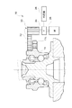
図1は組合せ軸受の構造を示す図である。自動車用ホイール軸受として用いられる組合せ軸受10は、内周に複列の転走面11a、11bが形成された外輪11、外輪11の転走面11bに対向する転走面12aが外周に形成された第1内輪12、外輪11の転走面11aに対向する転走面13aが外周に形成され、かつ第1内輪12が圧入される圧入部13cを連設したホイール軸として一体に形成された第2内輪13、外輪11と第1内輪12および第2内輪13との間に設けられたボール14a、14bが組み合わされた構造を有する。
[First Embodiment]
FIG. 1 is a view showing the structure of a combination bearing. A combination bearing 10 used as a wheel bearing for an automobile has an
第2内輪13の軸端部13eには凹部13fが形成されており、後述する揺動型加締め装置21のかしめ型26aと対向している。また、外輪11および第2内輪13には、それぞれフランジ部11cおよびフランジ部13dが形成されている。
A
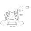
図2は揺動型加締め装置のワーク保持台に組合せ軸受が固定された状態を示す断面図である。揺動型加締め装置21は、フランジ部13dをボルト18で締め付けることにより組合せ軸受10を固定するワーク保持台23、ワーク保持台23に立設する部材24に取り付けられ、回転時に組合せ軸受10の振れ止めを行う振れ止め板25、かしめ型26aが取り付けられた押圧部26を有する。
FIG. 2 is a cross-sectional view showing a state in which the combination bearing is fixed to the work holding base of the swing type caulking device. The swing
このような揺動型加締め装置21では、押圧部26は組合せ軸受10の軸に対し僅かな傾きθを持って取り付けられており、揺動回転しながら軸端部13eに接近して凹部13fに収納されるかしめ型26aによって軸端部13eを内側から押圧する。
In such a swing
かしめ型26aによって押圧された軸端部13eは、第1内輪12によって外径側から拘束を受けた状態でかしめ型26aの形状を凹部13fの空間に充満させる形で徐々に変形する。軸端部13eの変形によって第1内輪12は軸方向に押し込まれて締め付けられる。これにより、第1内輪12の転走面12aと第2内輪13の転走面13aとが接近するので、外輪11と転動体14a、14bとの間に隙間がなくなり、第1、第2内輪12、13および外輪11間に介在する転動体14a、14b間に予圧が発生する。予圧量が予め設定された所定値に達すると、揺動型加締め装置21を後退させて加締め加工を終了する。図2では、加締め加工が終了した状態が示されている。
The
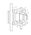
図3は組合せ軸受10に取り付けられた予圧モニタ装置の構成を概略的に示す図である。予圧モニタ装置30は、フランジ部11c上方の外輪11側面と接触するゴム部材が取り付けられた歯車32、歯車32と歯合する外輪回転用歯車33、歯車33を回転駆動するモータ(M)34、モータ34の回転トルクを検出するトルク検出器(T)35、および検出された回転トルクを予め設定された所定値と比較する判定器36を有する。トルク検出器35としては、電力計が用いられる。
FIG. 3 is a diagram schematically showing the configuration of the preload monitoring device attached to the combination bearing 10. The
予圧モニタ装置30では、モータ34を駆動し、歯車33、32を介して外輪11を回転させ、外輪11の回転トルクをトルク検出器35で検出し、検出された回転トルクに基づいて予圧を測定し、測定された予圧が予め設定された所定値、つまり組合せ軸受10に適した予圧に達した場合、揺動型加締め装置21を後退させる。
In the
そして、揺動型加締め装置21による加締め加工を終了した後も回転トルクを監視して予圧量が適正であることを確認する。
Even after the caulking process by the
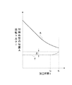
図4は加締め加工時間tに対する揺動型加締め装置21の加締め型26aの位置および回転トルクTの変化を示すグラフである。揺動型加締め装置21の加締め型26aの位置Aを徐々に降下させて加締め加工を開始すると、ある時点t0から組合せ軸受10に予圧が加わり回転トルクTが変動し始める。その変動幅が予め設定された所定幅Δにまで達すると(時点t1)、組合せ軸受10に適した予圧が加わったと判断して加締め加工を終了する。これにより、加締め型26aの位置Aを原点に復帰させる。
FIG. 4 is a graph showing changes in the position and rotational torque T of the
このように、本実施形態の軸受の予圧付与装置では、組合せ軸受10の加締め加工時に予圧量を適正に付与することができる。したがって、加締め不足、加締め過ぎといった軸受の性能上、不都合な不良品の発生を防止できる。 As described above, in the bearing preload application device of the present embodiment, the preload amount can be appropriately applied when the combined bearing 10 is caulked. Therefore, it is possible to prevent occurrence of inferior defective products in terms of bearing performance such as insufficient crimping and excessive crimping.
図5は外輪11を回転させる他の機構を示す図である。モータ134の軸先端部には側面にゴム部材が固着されたドライブホイール135が取り付けられている。ドライブホイール135は外輪11の軸方向の端面に接触しており、モータ135の回転動力を伝達して外輪11を回転させる。
FIG. 5 is a view showing another mechanism for rotating the
[第2の実施形態]
前記第1の実施形態では、外輪11の回転トルクを検出することにより組合せ軸受10の予圧を測定していたが、第2の実施形態では外輪11の振動を検出することにより予圧を測定する。組合せ軸受10および揺動型加締め装置21の構造については前記第1の実施形態と同様である。
[Second Embodiment]
In the first embodiment, the preload of the combination bearing 10 is measured by detecting the rotational torque of the
図6は第2の実施形態における予圧モニタ装置の構成を示す図である。この予圧モニタ装置40は、加振器41、加振用アンプ42、速度型振動センサ51、FFTスペクトル周波数分析器55および予圧判定器56から構成される。予圧判定器56には、差分演算器57、比較器58および信号発生器59が設けられている。
FIG. 6 is a diagram showing the configuration of the preload monitoring device in the second embodiment. The
速度型振動センサ(ムービングピックアップ)51は外輪11のフランジ部11cの下面に取り付けられており、加振器41によって与えられる振動を外輪11を介して検知する。
A speed type vibration sensor (moving pickup) 51 is attached to the lower surface of the
速度型振動センサ51によって検知された軸受の剛性に基づく振動信号は、FFTスペクトル周波数分析器55に入力される。周波数分析器55は速度型振動センサ51からの振動信号を分析して振動スペクトルを取得し、取得した振動スペクトルに基づき、縦軸を組合せ軸受10のコンプライアンスC、横軸を周波数fとするコンプライアンス曲線を得る。図7は縦軸を組合せ軸受10のコンプライアンスC、横軸を周波数fとするコンプライアンス曲線を示すグラフである。
A vibration signal based on the stiffness of the bearing detected by the speed
前記第1の実施形態における図4と同様に、加締め加工時間tの経過につれて加締め型26aの位置Aを降下させると、回転トルクTの場合と同様にある時点t0から組合せ軸受10の固有振動数が高くなり、コンプライアンスCのピーク周波数も高くなる。加締めを強くする程、組合せ軸受10の軸受隙間が減少するので、組合せ軸受10の固有振動数、すなわちコンプライアンスCのピーク周波数は高い方にシフトする。図7において、実線および点線はそれぞれ組合せ軸受10に予圧が加わる前後のコンプライアンス曲線を示す。
As in FIG. 4 in the first embodiment, when the position A of the
差分演算器57は予圧が加わる前の組合せ軸受10の固有振動数と予圧が加わった後の固有振動数との差分、つまり変化幅Δfを演算する(図7参照)。比較器58は、固有振動数の変化幅Δfが予め設定された組合せ軸受10の適正な予圧量に相当する幅に達したか否かを判定する。達していると判定された場合、信号発生器59は加締め終了信号を出力する。この加締め終了信号により、揺動型加締め装置21の加締め型26aの位置Aを原点に復帰させる。
The
このように、第2の実施形態の軸受の予圧付与装置では、前記第1の実施形態と同様に組合せ軸受の加締め加工時に予圧量を適正に付与することができる。 As described above, in the bearing preload application device according to the second embodiment, the preload amount can be appropriately applied during the caulking process of the combined bearing, as in the first embodiment.
尚、本実施形態では、加振器および振動センサをそれぞれフランジ部11cの上下端面に取り付けたが、外輪11の側面に取り付けるようにしてもよい。図8は外輪11の側面に取り付けられた加振器および振動センサの配置を示す図である。振動センサ141は速度型振動センサであり、フランジ部11c上方の外輪11の側面に取り付けられている。一方、加振器141は油圧式加振器であり、フランジ部11c下方の外輪11の側面に取り付けられている。加振器としては、油圧式のものに限らず、電動式のものでもよい。
In the present embodiment, the vibrator and the vibration sensor are respectively attached to the upper and lower end surfaces of the
10 組合せ軸受
11 外輪
12 第1内輪
13 第2内輪
14a、14b ボール
21 揺動型加締め装置
26a かしめ型
34 モータ
35 トルク検出器
36 判定器
41 加振器
51 振動センサ
55 周波数分析器
56 予圧判定器
DESCRIPTION OF
Claims (1)
前記内輪に対して行われる締め付けを増加させる締付増加手段と、
前記予圧を検出する予圧検出手段と、
該検出される予圧が所定値に達したか否かを判別する予圧判別手段と、
該予圧が所定値に達した場合、前記内輪に対して行われる締め付けを解除する締付解除手段とを備え、
該締め付けの解除により前記軸受の組み立てを完了することを特徴とする軸受の予圧付与装置。 In the bearing preload application device for assembling the bearing by applying a preload to the rolling elements interposed between the inner ring and the outer ring by tightening the inner ring in the axial direction,
Tightening increasing means for increasing tightening performed on the inner ring;
Preload detecting means for detecting the preload;
Preload determining means for determining whether or not the detected preload has reached a predetermined value;
A tightening release means for releasing the tightening performed on the inner ring when the preload reaches a predetermined value;
A bearing preload applying device characterized in that the assembly of the bearing is completed by releasing the tightening.
Priority Applications (1)
| Application Number | Priority Date | Filing Date | Title |
|---|---|---|---|
| JP2005069740A JP2005201456A (en) | 2005-03-11 | 2005-03-11 | Assembling method of rolling bearing unit for supporting wheel |
Applications Claiming Priority (1)
| Application Number | Priority Date | Filing Date | Title |
|---|---|---|---|
| JP2005069740A JP2005201456A (en) | 2005-03-11 | 2005-03-11 | Assembling method of rolling bearing unit for supporting wheel |
Related Parent Applications (1)
| Application Number | Title | Priority Date | Filing Date |
|---|---|---|---|
| JP9216996A Division JPH1144319A (en) | 1997-07-29 | 1997-07-29 | Pre-load applying device for bearing |
Publications (2)
| Publication Number | Publication Date |
|---|---|
| JP2005201456A true JP2005201456A (en) | 2005-07-28 |
| JP2005201456A5 JP2005201456A5 (en) | 2005-09-22 |
Family
ID=34824842
Family Applications (1)
| Application Number | Title | Priority Date | Filing Date |
|---|---|---|---|
| JP2005069740A Pending JP2005201456A (en) | 2005-03-11 | 2005-03-11 | Assembling method of rolling bearing unit for supporting wheel |
Country Status (1)
| Country | Link |
|---|---|
| JP (1) | JP2005201456A (en) |
Cited By (2)
| Publication number | Priority date | Publication date | Assignee | Title |
|---|---|---|---|---|
| JP2014073734A (en) * | 2012-10-03 | 2014-04-24 | Nsk Ltd | Wheel support roller bearing unit and manufacturing method thereof |
| JP2016114250A (en) * | 2016-01-07 | 2016-06-23 | 日本精工株式会社 | Rolling bearing unit for wheel support |
-
2005
- 2005-03-11 JP JP2005069740A patent/JP2005201456A/en active Pending
Cited By (2)
| Publication number | Priority date | Publication date | Assignee | Title |
|---|---|---|---|---|
| JP2014073734A (en) * | 2012-10-03 | 2014-04-24 | Nsk Ltd | Wheel support roller bearing unit and manufacturing method thereof |
| JP2016114250A (en) * | 2016-01-07 | 2016-06-23 | 日本精工株式会社 | Rolling bearing unit for wheel support |
Similar Documents
| Publication | Publication Date | Title |
|---|---|---|
| JPH1144319A (en) | Pre-load applying device for bearing | |
| JPH1096672A (en) | Apparatus for measuring pilot pressure of bearing | |
| JPH07217649A (en) | Method of measuring pre-load clearance of double row rolling bearing and device therefor | |
| JP5599842B2 (en) | Endurance test method for constant velocity joints | |
| JP2020098163A (en) | Starting torque measurement method of bearing device | |
| JP2005201456A (en) | Assembling method of rolling bearing unit for supporting wheel | |
| JP2008070305A (en) | Method of measuring radial clearance of single-row radial ball bearing | |
| JP2005282866A (en) | Assembling method of rolling bearing unit for supporting wheel | |
| JP3254825B2 (en) | Manufacturing method of rolling bearing device to which preload is applied | |
| JPH07324972A (en) | Apparatus for measuring vibration of roller bearing | |
| CN103080580B (en) | For the rubbing device of bearing unit, comprise bearing unit and the bearing of this rubbing device | |
| JP2009281426A (en) | Lock nut | |
| JP4353870B2 (en) | Method of measuring clearance of wheel bearing device | |
| JP2874388B2 (en) | Preload measurement method for rolling ball bearings | |
| JPH0874844A (en) | Pre-pressure estimation method and device for bearing device for vehicular shaft | |
| JP2003194082A (en) | Method and device for assembling tapered roller bearing, and tapered roller bearing assembly | |
| JP2017114375A (en) | Bearing device | |
| JP2005325902A (en) | Method for manufacturing wheel bearing device | |
| JP4341350B2 (en) | Screw tightening method | |
| JP2007120558A (en) | Locking structure for screw-cover of machine | |
| WO2022039204A1 (en) | Rotational torque inspection method for wheel bearing device, and rotational torque inspection device for wheel bearing device | |
| JP4994617B2 (en) | Processing method of wheel bearing device | |
| JP4952617B2 (en) | Method and apparatus for adjusting preload of rotating shaft | |
| JP5233367B2 (en) | Processing method of rolling bearing device for wheel | |
| JP4647333B2 (en) | Cutting method of braking surface of wheel bearing device with brake rotor |
Legal Events
| Date | Code | Title | Description |
|---|---|---|---|
| A521 | Written amendment |
Free format text: JAPANESE INTERMEDIATE CODE: A523 Effective date: 20050630 |
|
| RD03 | Notification of appointment of power of attorney |
Free format text: JAPANESE INTERMEDIATE CODE: A7423 Effective date: 20060426 |
|
| A131 | Notification of reasons for refusal |
Free format text: JAPANESE INTERMEDIATE CODE: A131 Effective date: 20060926 |
|
| A02 | Decision of refusal |
Free format text: JAPANESE INTERMEDIATE CODE: A02 Effective date: 20070206 |