JP2005199777A - Tire state display device - Google Patents
Tire state display device Download PDFInfo
- Publication number
- JP2005199777A JP2005199777A JP2004006139A JP2004006139A JP2005199777A JP 2005199777 A JP2005199777 A JP 2005199777A JP 2004006139 A JP2004006139 A JP 2004006139A JP 2004006139 A JP2004006139 A JP 2004006139A JP 2005199777 A JP2005199777 A JP 2005199777A
- Authority
- JP
- Japan
- Prior art keywords
- wheel
- tire
- display
- air pressure
- sensor
- Prior art date
- Legal status (The legal status is an assumption and is not a legal conclusion. Google has not performed a legal analysis and makes no representation as to the accuracy of the status listed.)
- Pending
Links
- 230000005856 abnormality Effects 0.000 claims description 15
- 230000002159 abnormal effect Effects 0.000 claims description 3
- 238000000034 method Methods 0.000 description 7
- 238000001514 detection method Methods 0.000 description 3
- 238000012423 maintenance Methods 0.000 description 3
- 238000012986 modification Methods 0.000 description 3
- 230000004048 modification Effects 0.000 description 3
- 230000001133 acceleration Effects 0.000 description 2
- 239000003086 colorant Substances 0.000 description 2
- 238000004891 communication Methods 0.000 description 2
- 238000010586 diagram Methods 0.000 description 2
- 238000005516 engineering process Methods 0.000 description 2
- 238000007689 inspection Methods 0.000 description 2
- 230000005540 biological transmission Effects 0.000 description 1
- 230000004397 blinking Effects 0.000 description 1
- 239000000470 constituent Substances 0.000 description 1
- 230000003247 decreasing effect Effects 0.000 description 1
- 238000009434 installation Methods 0.000 description 1
- 238000004519 manufacturing process Methods 0.000 description 1
- 238000012544 monitoring process Methods 0.000 description 1
- 238000012545 processing Methods 0.000 description 1
- 239000004065 semiconductor Substances 0.000 description 1
Images


Classifications
-
- B—PERFORMING OPERATIONS; TRANSPORTING
- B60—VEHICLES IN GENERAL
- B60C—VEHICLE TYRES; TYRE INFLATION; TYRE CHANGING; CONNECTING VALVES TO INFLATABLE ELASTIC BODIES IN GENERAL; DEVICES OR ARRANGEMENTS RELATED TO TYRES
- B60C23/00—Devices for measuring, signalling, controlling, or distributing tyre pressure or temperature, specially adapted for mounting on vehicles; Arrangement of tyre inflating devices on vehicles, e.g. of pumps or of tanks; Tyre cooling arrangements
- B60C23/02—Signalling devices actuated by tyre pressure
- B60C23/04—Signalling devices actuated by tyre pressure mounted on the wheel or tyre
- B60C23/0401—Signalling devices actuated by tyre pressure mounted on the wheel or tyre characterised by the type of alarm
-
- B—PERFORMING OPERATIONS; TRANSPORTING
- B60—VEHICLES IN GENERAL
- B60C—VEHICLE TYRES; TYRE INFLATION; TYRE CHANGING; CONNECTING VALVES TO INFLATABLE ELASTIC BODIES IN GENERAL; DEVICES OR ARRANGEMENTS RELATED TO TYRES
- B60C23/00—Devices for measuring, signalling, controlling, or distributing tyre pressure or temperature, specially adapted for mounting on vehicles; Arrangement of tyre inflating devices on vehicles, e.g. of pumps or of tanks; Tyre cooling arrangements
- B60C23/02—Signalling devices actuated by tyre pressure
- B60C23/04—Signalling devices actuated by tyre pressure mounted on the wheel or tyre
- B60C23/0408—Signalling devices actuated by tyre pressure mounted on the wheel or tyre transmitting the signals by non-mechanical means from the wheel or tyre to a vehicle body mounted receiver
Abstract
Description
本発明は、車輪に設けられたセンサで検出されたタイヤ空気圧などのタイヤ状態情報を車輪の装着位置と対応させて表示可能なタイヤ状態表示装置に関する。 The present invention relates to a tire state display device capable of displaying tire state information such as tire air pressure detected by a sensor provided on a wheel in association with a wheel mounting position.
車両を安全に走行させるためには、タイヤを含む車輪の状態を正常に保つことが必要である。したがって、タイヤの空気圧不足などの異常が車輪に発生したときには、これを速やかに検出して適切な処置を講ずる必要がある。 In order to drive the vehicle safely, it is necessary to keep the state of the wheels including the tires normal. Therefore, when an abnormality such as insufficient tire air pressure occurs in the wheel, it is necessary to promptly detect this and take appropriate measures.
タイヤに発生した異常をユーザに警報する技術として、特許文献1には、車輪位置に対応させたタイヤ圧力警告表示ランプを備えるタイヤ圧力監視システムが開示されている。また、特許文献2には、複数のタイヤにそれぞれ識別表示の異なるセンサ装置を装着しておき、タイヤ空気圧異常の発生時には、その異常を検出したセンサに施された識別表示を表示器に表示させる技術が開示されている。
しかしながら、上記特許文献1では、タイヤ圧力情報を送信する各送信機のコードが車輪の装着位置に対応付けてプログラムされているので、タイヤローテーションをした場合には車輪位置の再学習が必要となる。この際にタイヤローテーション前後の車輪位置を入力する必要があり、ローテーション前後の車輪位置を正確に記憶して入力しないと誤設定する可能性がある上に、設定後の車輪位置に間違いがないかを確認することができないといった問題がある。また、上記特許文献2では、異常の発生時、ユーザは表示器に表示されたものと同一の識別表示が施されているタイヤを探さなければならず、車外に出ることなく異常の発生した車輪位置を特定できない。
However, in
本発明はこうした状況に鑑みてなされたものであり、その目的は、車輪に設けられたセンサで検出されたタイヤ状態情報を車輪の装着位置と対応させて表示するとともに、この対応付けを簡単かつ正確に行える技術を提供することにある。 The present invention has been made in view of such a situation, and an object thereof is to display tire state information detected by a sensor provided on a wheel in association with a mounting position of the wheel, and to make this association simple and easy. It is to provide a technology that can be accurately performed.
上記課題を解決するために、本発明のある態様は、車両の各車輪に設けられタイヤ状態を検出するセンサであって、相異なる識別表示がユーザの視認可能な位置に付されているセンサと、前記センサにより検出されたタイヤ状態情報と前記識別表示の情報を共に送信する送信手段と、前記センサが設けられている車輪の前記車両への装着位置と前記識別表示との対応関係をユーザに入力させるユーザ入力手段と、入力された前記対応関係に基づいて、前記タイヤ状態情報を前記車輪の装着位置に対応させてユーザに表示する表示手段とを備えるタイヤ状態表示装置を提供する。 In order to solve the above-described problems, an aspect of the present invention is a sensor that is provided on each wheel of a vehicle and detects a tire state, and a sensor in which a different identification display is attached to a position that can be visually recognized by a user. The transmission means for transmitting both the tire condition information detected by the sensor and the information on the identification display, and the correspondence between the mounting position of the wheel provided with the sensor on the vehicle and the identification display to the user There is provided a tire condition display device comprising user input means for inputting and display means for displaying the tire condition information in correspondence with the mounting position of the wheel based on the inputted correspondence relationship.
ここで「タイヤ状態」とは、タイヤの空気圧、温度、接地面のウェット/ドライ情報、タイヤの摩耗量、加速度、歪みなど、車輪に設けたセンサで取得される物理量のことを指す。また、「識別表示」とは、外部から観察でき、かつユーザが簡単に理解、記憶できる表示のことを指し、例えば、色、数字、符号、アルファベット、図形などを含む。この識別表示は、タイヤの空気バルブなどのタイヤから分離されない場所に付加される。「ユーザ入力手段」には、ボタン、タッチパネルなどが含まれる。「表示手段」とは、一例では車室内に備えられたLCDであるが、カーナビゲーションシステムの画面やLEDを用いた表示であってもよい。車両外部に情報を送信可能な送信機を備えている場合には、ハンディタイプの検査装置に表示をする場合も含む。 Here, “tire condition” refers to a physical quantity acquired by a sensor provided on a wheel, such as tire pressure, temperature, contact surface wet / dry information, tire wear, acceleration, and strain. The “identification display” refers to a display that can be observed from the outside and can be easily understood and stored by the user, and includes, for example, colors, numbers, codes, alphabets, and figures. This identification indication is added to a place that is not separated from the tire, such as an air valve of the tire. “User input means” includes buttons, a touch panel, and the like. The “display means” is an LCD provided in the passenger compartment in one example, but may be a display using a screen of a car navigation system or LEDs. In the case where a transmitter capable of transmitting information to the outside of the vehicle is provided, the display includes a handy type inspection device.
この態様によると、センサにより検出されたタイヤ状態情報と識別表示が車輪から送信されてくると共に、前記センサが設けられている車輪の車両への装着位置と前記識別表示との対応をユーザに入力させるので、タイヤ状態表示装置はタイヤ状態情報を車輪の装着位置に対応させて表示手段に表示することができる。また、各車輪から送信されてくるタイヤ状態情報がどの車輪に対応するかを決定することができないような構成の車両であっても、タイヤ状態表示装置は、センサによるタイヤ状態の検出に先立って輪判定を実行したり、センサの識別番号を車輪の装着位置に対応させてプログラムしておいたりする必要がない。 According to this aspect, the tire condition information detected by the sensor and the identification display are transmitted from the wheel, and the correspondence between the mounting position of the wheel provided with the sensor on the vehicle and the identification display is input to the user. Therefore, the tire condition display device can display the tire condition information on the display means in association with the wheel mounting position. In addition, even if the vehicle has a configuration in which the tire state information transmitted from each wheel cannot determine which wheel corresponds to the tire state display device, the tire state display device prior to the detection of the tire state by the sensor. There is no need to perform wheel determination or program the sensor identification number in correspondence with the wheel mounting position.
前記表示手段は、前記ユーザ入力手段による入力の際に、前記識別表示と前記車輪の装着位置との対応をユーザが視覚的に確認可能な画面を表示してもよい。 The display means may display a screen on which a user can visually confirm the correspondence between the identification display and the mounting position of the wheel upon input by the user input means.
ここで、「ユーザ」とは車両のドライバーに限られず、組立工場や整備工場の作業員も含む。したがって、「ユーザ入力手段による入力の際」とは、組立工場で車両に車輪を装着したり、整備工場でタイヤローテーションを行ったり、または車輪の一部を新しい車輪に交換したりした後に、車輪の車両への装着位置と識別表示の対応関係を入力することを指す。この態様によると、ユーザは車輪の装着位置と識別表示との対応関係を視覚的に確認しながら入力できるので、前記対応関係の入力を簡単かつ正確に行うことが可能となる。 Here, the “user” is not limited to the driver of the vehicle, but includes workers in assembly factories and maintenance factories. Therefore, “when inputting by the user input means” means that after mounting a wheel on a vehicle at an assembly plant, rotating a tire at a maintenance plant, or exchanging part of the wheel for a new wheel, This refers to inputting the correspondence between the position of the vehicle mounted on the vehicle and the identification display. According to this aspect, since the user can input while visually confirming the correspondence between the wheel mounting position and the identification display, the correspondence can be input easily and accurately.
タイヤ状態表示装置は、前記タイヤ状態情報に基づいてタイヤの異常を判定する判定手段をさらに備えてもよい。この場合、前記表示手段は、異常と判定された車輪の装着位置を表示する。この態様によると、異常が発生した車輪の装着位置を視覚的に確認できるので、ユーザは異常を速やかに把握することができる。 The tire condition display device may further include a determination unit that determines tire abnormality based on the tire condition information. In this case, the display means displays the mounting position of the wheel determined to be abnormal. According to this aspect, since the mounting position of the wheel in which the abnormality has occurred can be visually confirmed, the user can quickly grasp the abnormality.
前記センサに固有の識別番号が予め付与されている場合には、前記識別表示は前記識別番号と関連付けられていてもよい。この場合、車体側がセンサの識別番号を受信すれば、識別表示の情報も得られることになり、識別表示の情報を車輪側から車体側に送信する必要がなくなるので、データ通信量が低減される。 When a unique identification number is assigned in advance to the sensor, the identification display may be associated with the identification number. In this case, if the vehicle body side receives the sensor identification number, information on the identification display can be obtained, and it is not necessary to transmit the information on the identification display from the wheel side to the vehicle body side, so the amount of data communication is reduced. .
なお、以上の構成要素の任意の組合せや、本発明の表現を方法として表現したものもまた、本発明の態様として有効である。 It should be noted that any combination of the above-described constituent elements and what expresses the expression of the present invention as a method are also effective as an aspect of the present invention.
本発明によるタイヤ状態表示装置によれば、車輪に設けられたセンサで検出されたタイヤ状態情報を車輪の装着位置と対応させて表示するとともに、この対応付けを簡単かつ正確に行うことができる。 According to the tire condition display device of the present invention, the tire condition information detected by the sensor provided on the wheel can be displayed in correspondence with the mounting position of the wheel, and this association can be performed easily and accurately.
本発明の一実施形態は、車輪から送信されてくる情報だけでは各センサの設けられている車輪の装着位置を特定できないシステムにおいて、タイヤの空気バルブに識別表示を付加しておき、タイヤの交換・交替時にその識別表示と車輪の装着位置との対応をユーザに入力させることで、タイヤ空気圧を車輪位置に対応させて表示することができる装置である。 According to an embodiment of the present invention, in a system in which the mounting position of a wheel provided with each sensor cannot be specified only by information transmitted from the wheel, an identification display is added to the tire air valve, and the tire is replaced. -It is a device that can display the tire pressure corresponding to the wheel position by allowing the user to input the correspondence between the identification display and the wheel mounting position at the time of replacement.
図1は、本発明の一実施形態に係るタイヤ状態表示装置10を備えた車両12の全体構成を示す。車両12の4個の車輪及びスペアタイヤにはそれぞれ、監視すべきタイヤの空気圧を検出する空気圧センサ、空気圧センサにより検出されたタイヤ空気圧情報を無線で車体側に送信する送信機、およびアンテナが設けられている。第1車輪20aのホイールには、第1空気圧センサ30a、第1送信機40a、および第1アンテナ50aが設けられている。第2車輪20bのホイールには、第2空気圧センサ30b、第2送信機40b、および第2アンテナ50bが設けられている。第3車輪20cのホイールには、第3空気圧センサ30c、第3送信機40c、および第3アンテナ50cが設けられている。第4車輪20dのホイールには、第4空気圧センサ30d、第4送信機40d、および第4アンテナ50dが設けられている。第5車輪20eのホイールには、第5空気圧センサ30e、第5送信機40e、および第5アンテナ50eが設けられている。なお、第5車輪20eはスペアタイヤである。
FIG. 1 shows an overall configuration of a
以下、第1車輪20a、第2車輪20b、第3車輪20c、第4車輪20dおよび第5車輪20eを総称して「車輪20」と呼び、第1空気圧センサ30a、第2空気圧センサ30b、第3空気圧センサ30c、第4空気圧センサ30dおよび第5空気圧センサ30eを総称して「空気圧センサ30」と呼ぶ。また、第1送信機40a、第2送信機40b、第3送信機40c、第4送信機40dおよび第5送信機40eを総称して「送信機40」と呼び、第1アンテナ50a、第2アンテナ50b、第3アンテナ50c、第4アンテナ50dおよび第5アンテナ50eを総称して「車輪側アンテナ50」と呼ぶ。
Hereinafter, the
各空気圧センサ30は、検出したタイヤ空気圧情報をそれぞれ対応する送信機40に送る。各送信機40は、受け取ったタイヤ空気圧情報をそれぞれ対応する車輪側アンテナ50を介して車体側のアンテナ72へ送信する。空気圧センサ30と送信機40は電池(図示せず)を電源として駆動される。
Each air pressure sensor 30 sends the detected tire pressure information to the corresponding transmitter 40. Each transmitter 40 transmits the received tire pressure information to the
受信機70は、車体に設けられたアンテナ72を介して5つの送信機40からタイヤ空気圧情報を受信する。なお、受信機70は、車体が備えるバッテリー(図示せず)を電源として駆動される。
The
受信機70は、受信したタイヤ空気圧情報を電子制御装置(以下、「ECU」と呼ぶ)60に送る。ECU60は、後述するように、ユーザ入力部74から送られる情報に基づいて、送信されてきたタイヤ空気圧情報と車輪の装着位置とを結びつけて、車室内に備えられているLCDなどの表示部76に表示する。これによってドライバーは、視覚的に各タイヤの現在の空気圧状態を知ることができる。表示部76は、カーナビゲーションシステムの画面であってもよい。
The
ECU60は、定期的にタイヤ空気圧を監視しており、タイヤ空気圧情報に基づいて車輪20の状態を判断する。そして、ECU60は、タイヤ空気圧が所定のしきい値を下回っていた場合には、表示部76にタイヤ空気圧が低下している旨の警告表示をする。
The ECU 60 periodically monitors the tire air pressure, and determines the state of the
リセットスイッチ78は、車室内などに備えられ、ECU60に記憶されている情報をリセットして、後述するような、ユーザによる車輪の装着位置と識別表示との対応関係の入力を可能にする。リセットスイッチ78は、組立工場での車輪の装着、タイヤローテーション、またはタイヤの交換を行ったときにオンにされる。
The
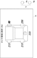
図2は、空気圧センサ30の車輪20への取り付けを説明する図である。空気圧センサ30は、タイヤの空気バルブ及び送信機40と一体化されてバルブ構成体24を構成している。バルブ構成体24のハウジング28内には、空気圧センサ30と、送信機40と、車輪側アンテナ50が収容されている。
FIG. 2 is a view for explaining attachment of the air pressure sensor 30 to the
バルブ構成体24は、車輪20のホイールリム22に穿設されたバルブ取り付け孔に差し込まれる。バルブ構成体24のホイールリム22を貫通する部分には弾性ゴム製のグロメット29が嵌挿されており、これによってタイヤ内部を気密構造とするとともに、タイヤの回転に伴う振動でバルブ構成体24が損傷することを防止している。バルブ構成体24は、ホイールリム22の外側からワッシャ23及びナット27によってホイールリム22に固定される。タイヤ内部を気密とし、またバルブ構成体24の外れを防止するため、ナット27のトルクは適切に管理されることが好ましい。
The
バルブ構成体24は、ホイールリム外部に突き出すバルブキャップ25を備える。バルブキャップ25を外すとバルブコアの弁口部(図示せず)が現れる。バルブコアの弁口部は図示しない通孔によってタイヤ内部と連通しており、空気の供給を可能としている。
The
空気圧センサ30は例えば半導体圧力センサであり、タイヤ内の空気圧を検出し、送信機40を介してタイヤ空気圧情報を車体側に送信する。空気圧センサ30による空気圧の検出は常時行ってもよいし、定期的に行ってもよい。後者の場合は、空気圧センサ30及び送信機40の消費電力を低減して電池寿命を延ばすことができる。 The air pressure sensor 30 is, for example, a semiconductor pressure sensor, detects the air pressure in the tire, and transmits tire air pressure information to the vehicle body side via the transmitter 40. The detection of air pressure by the air pressure sensor 30 may be performed constantly or periodically. In the latter case, the power consumption of the air pressure sensor 30 and the transmitter 40 can be reduced and the battery life can be extended.
各センサに付される相異なる識別表示は、例えば図2中のバルブ部分26に付加される。図2では、識別表示としてセンサ毎に色が塗り分けられる場合を示している。例えば、FR輪、FL輪、RR輪、RL輪及びスペアタイヤに対し、赤、青、緑、白及び黒色で塗り分けられる。色以外であっても、外部から観察でき、かつユーザが簡単に理解、記憶できる表示であればよく、例えば数字、符号、アルファベット、図形などでもよい。識別表示の付加場所は、上記のバルブ部分26に限定されないが、空気圧センサ30との対応がくずれないように、バルブ構成体24のうち取り外しできる部分、例えばバルブキャップ25やナット27などに付加するのは好ましくない。
The different identifications attached to each sensor are added to the
図3は、ECU60のうちタイヤ空気圧情報の表示に関与する部分の構成を示す図である。以下では、本実施形態において、空気圧センサ30により検出されたタイヤ空気圧情報と車輪の装着位置とを対応させて表示部76に表示する方法について説明する。
FIG. 3 is a diagram illustrating a configuration of a part related to the display of tire pressure information in the
各空気圧センサ30には、製造時に予め固有の識別番号が付与されている(以下、この識別番号を「センサID」と呼ぶ)。上述した各空気圧センサ30の識別表示は、このセンサIDと関連付けられている。関連付けは、例えば空気圧センサ30に付与されているセンサIDの下一桁に対して、以下の表1に示すようになされる。

各車輪20に設けられている送信機40は、空気圧センサ30で検出されたタイヤ空気圧情報と、当該空気圧センサ30のセンサIDとを一緒に車体側の受信機70に送信する。上述のように、センサIDと識別表示は関連付けされているので、このときに各空気圧センサの識別表示の情報も車体側に送信されることになる。このような関連付けをせずに、識別表示の情報をセンサIDとは別に送信してもよい。
The transmitter 40 provided in each
受信機70を介して受け取られたタイヤ空気圧情報とセンサIDとは、ECU60内のマッチング部62に入力される。マッチング部62は、車両12に装着された全ての車輪20から、タイヤ空気圧情報とそれを検出した空気圧センサ30のセンサIDの組を受け取るが、それぞれのタイヤ空気圧情報がどの車輪位置、つまり、FR輪、FL輪、RR輪、RL輪またはスペアタイヤに対応するのかを認識することができない。
Tire pressure information and sensor ID received via the
そこで、ECU60内の画面制御部66は、ユーザに対し、各空気圧センサ30の識別表示と車輪の装着位置との対応関係を入力するよう要求する画面を表示部76に表示する。そして、ユーザは、各車輪のバルブ構成体24に施されている識別表示を目視確認し、ユーザ入力部74を使用して、例えば、FR輪は黒、FL輪は白といったように車輪の装着位置に対応する識別表示を入力していく。このとき、画面制御部66はユーザの入力を支援するための画面を表示部76に表示するが、この画面については図5を参照して後述する。ユーザがこの対応関係の入力を行うと、マッチング部62はこの情報を利用して、タイヤ空気圧情報と車輪の装着位置とを対応付けることが可能となる。そして、画面制御部66は、タイヤ空気圧情報を車輪の装着位置に対応させて表示部76に表示する。
Therefore, the
圧力判定部64は、各車輪20のタイヤ空気圧情報を定期的に監視しており、タイヤ空気圧情報と予め定められたしきい値とを比較して、空気圧が正常な範囲にあるか否かを判定する。圧力判定部64でタイヤ空気圧が異常と判定された場合、画面制御部66は表示部76にタイヤ空気圧異常警報を表示する。
The
図1を参照して説明したような、各車輪から送信されてくるタイヤ状態情報を受信するためのアンテナを1つまたは2つしか備えていないような車両では、受信したタイヤ状態情報がどの車輪に関しての情報であるかを決定することができない。 In a vehicle having only one or two antennas for receiving tire condition information transmitted from each wheel, as described with reference to FIG. 1, which wheel has the received tire condition information. It is not possible to determine what information is about.
そこで、本実施形態では、ECU60はまず、各車輪20の送信機40から一緒に送られてくるタイヤ空気圧情報とセンサIDを用いて、タイヤ空気圧情報とそれを検出した空気圧センサの識別表示の組合せを作っておく。次に、車輪20に施された識別表示とその車輪の装着位置との対応関係をユーザに入力させる。これら2つのステップで、ECU60は、タイヤ空気圧情報と車輪の装着位置を対応させた表示をすることができる。これによってユーザは、タイヤに異常が発生した場合に、タイヤの状態を目視確認したり車輪の識別表示を確認したりする必要なく、即座に異常が発生した車輪位置を認識することができる。
Therefore, in the present embodiment, the
また、上述のように、センサIDと識別符号との関連付けを行っておくことで、工場などでECU60へのセンサIDと識別表示との対応付けを入力する必要がなくなる。また、車体側がセンサの識別番号を受信すれば、識別表示の情報も得られることになり、識別表示の情報を車輪側から車体側に送信する必要がなくなるので、データ通信量も低減される。
Further, as described above, by associating the sensor ID with the identification code, it is not necessary to input a correspondence between the sensor ID and the identification display to the
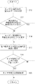
次に、図4のフローチャートを参照して、タイヤ状態表示装置の設定、タイヤ空気圧情報の表示及びタイヤ空気圧の警報までの流れを説明する。まず、ECU60は、受信機70を介して各車輪20からタイヤ空気圧情報とセンサIDとを受信する(S10)。次に、マッチング部62は、各空気圧センサ30の識別表示と車輪の装着位置との対応関係がマッチング部62内に登録されているか否かを確認する(S12)。組立工場での車輪の装着直後の場合、またはタイヤローテーション等を実行したためにリセットスイッチ78がオンにされ、対応関係の情報がリセットされていた場合(S12のNO)、画面制御部66は、ユーザに識別表示と車輪の装着位置との対応関係を入力するように促す画面を表示部76に表示する(S14)。
Next, with reference to the flowchart of FIG. 4, the flow from setting the tire condition display device, displaying tire pressure information, and warning of tire pressure will be described. First, the
図5は、このときに表示部76に表示される識別表示設定画面の一例である。図5には、表示部76と、その側に備えられたユーザ入力部74であるボタン74a、74bが示されている。表示部76は例えばLCDであり、車室内でユーザの目が届く場所に設置される。
FIG. 5 is an example of an identification display setting screen displayed on the
画面には、車両12の平面図と車輪20の装着位置が模式的に表示され、各車輪の横に、対応する空気圧センサ30の識別表示の色を設定できるようになっている。図5では、FR輪に「黒」が、FL輪に「白」が既に設定されている。RR輪とスペアタイヤは未設定である。RL輪については、現在選択中であることを示すために「緑」の表示が点滅している。ユーザは、車輪位置選択ボタン74aを押して、識別表示を設定する車輪の位置を選択する。選択した車輪位置において識別表示選択ボタン74bを押すたびに、色の表示が例えば赤、青、緑、白、黒の順で切り替わるようになっており、ユーザは各車輪について目視確認した色を設定する。一度設定した色は、他の車輪では選択できないようにしてもよい。ボタン74a、74bの配置や種類は任意である。なお、色の表示は図5のように文字で表示するほか、識別表示の色のランプが車輪位置に表示されるようにしてもよい。また、識別表示の種類に応じて表示部76の表示が変わることは言うまでもない。例えば、識別表示がアルファベットであった場合は、識別表示選択ボタン74bを押すたびに、A、B、C、D、Eの順で切り替わる。表示部76がタッチパネルになっている場合は、ボタン74a、74bが画面内に表示されてもよい。また、設定した識別表示と車輪位置を画面上に再表示できるボタンを設け、設定後の再確認が可能なようにしてもよい。全ての車輪20について識別表示の設定が終了すると、次のステップに進む。
On the screen, the plan view of the
ユーザから識別表示と車輪の装着位置の対応関係が入力された場合、または、対応関係が既にマッチング部62に登録されていたと確認された場合(S12のYES)、画面制御部66は、各車輪20のタイヤ空気圧情報を車輪の装着位置に対応させて表示部76に表示する(S16)。図6は、このときに表示部76に表示されるタイヤ空気圧表示画面の一例である。図5の識別表示設定画面と同様に、車両12の平面図と車輪20の装着位置が模式的に表示され、各車輪の横に対応するタイヤ空気圧情報が表示される。
When the correspondence between the identification display and the mounting position of the wheel is input from the user, or when it is confirmed that the correspondence has already been registered in the matching unit 62 (YES in S12), the
続いて、圧力判定部64は、送信されてきた各車輪20のタイヤ空気圧が所定のしきい値を下回ったか否かを判定する(S18)。タイヤ空気圧がしきい値以上の場合(S18のNO)、このルーチンを終了する。タイヤ空気圧がしきい値を下回った場合(S18のYES)、画面制御部66は表示部76にタイヤ空気圧の警報表示をする(S20)。図6では、FR輪のタイヤ空気圧が所定のしきい値を下回ったので、そのことをユーザに警報すべく、FR輪及びそのタイヤ空気圧が強調して表示されている。このような強調表示をすると共に図示しないブザーで警報音を鳴らしたり、通常画面とは異なる警告画面を表示したりしてもよい。
Subsequently, the
以上説明したように、本実施形態によれば、ユーザが識別表示と車輪の装着位置との対応関係を入力する際に、図5に示すような画面が表示部76に表示され、車輪の装着位置を視覚的に確認しながら入力でき、また入力後にその対応関係を再確認することができるため、ユーザの誤入力が少なくなる。また、センサIDと車輪位置の対応を登録する必要がないので、タイヤローテーション等を実行した後の設定が簡単になる。 As described above, according to the present embodiment, when the user inputs the correspondence between the identification display and the wheel mounting position, a screen as shown in FIG. Since the position can be input while visually confirming, and the correspondence can be reconfirmed after the input, erroneous input by the user is reduced. In addition, since it is not necessary to register the correspondence between the sensor ID and the wheel position, the setting after performing tire rotation or the like is simplified.
また、図6に示すような画面に車輪の装着位置と対応させてタイヤ空気圧を表示するので、ユーザは車両に乗車したまま各車輪のタイヤ状態を簡単に把握することができる。さらに、タイヤに異常が発生した場合、ユーザはタイヤの目視確認をしたり各車輪に施されている識別表示を探したりする必要なく、どの車輪に異常が発生したかを速やかに把握することができる。 Further, since the tire air pressure is displayed on the screen as shown in FIG. 6 in correspondence with the mounting position of the wheel, the user can easily grasp the tire state of each wheel while getting on the vehicle. In addition, when an abnormality occurs in a tire, the user can quickly grasp which wheel has an abnormality without having to visually check the tire or search for an identification display on each wheel. it can.
本発明には以下のような利点もある。すなわち、各車輪から送信されてくる情報を受信するための受信アンテナを1つまたは2つしか備えていないような車両では、受信したタイヤ状態情報がどの車輪、つまり、FR輪、FL輪、RR輪、RL輪またはスペアタイヤに対応するのかを決定することができない。そこで従来では、このような場合には、タイヤ状態情報がどの車輪からのものであるかを判別すべく、輪判定を行っていた。この輪判定は、各車輪の路面μ勾配を推定するものや、動加重半径を算出するものなど複数の方法が知られているが、いずれの場合も実際に車輪を判定できるようになるまでにある程度の距離を走行しなければならない。したがって、輪判定が完了するまでは送信されてきたタイヤ状態情報を活用できないという問題があった。また、タイヤローテーション等を実行したときには、同様の輪判定を繰り返す必要があった。輪判定を実行せずにどの車輪からの情報であるかを判別するために、車輪毎に受信アンテナを設ける方法も知られているが、これにはコストがかかる。本発明では、ユーザに識別表示と車輪の装着位置との対応関係についての簡単な入力をさせることで、車両に受信アンテナが1つまたは2つしか備えられていない場合であっても輪判定が不要になり、また走行開始直後から、車輪より送信されてくるタイヤ状態情報を利用した警報を実行することができる。 The present invention also has the following advantages. That is, in a vehicle having only one or two receiving antennas for receiving information transmitted from each wheel, which wheel, that is, the FR wheel, FL wheel, RR, It cannot be determined whether it corresponds to a wheel, RL wheel or spare tire. Therefore, conventionally, in such a case, wheel determination is performed in order to determine which wheel the tire condition information is from. There are several methods for determining the wheel, such as estimating the road surface μ gradient of each wheel and calculating the dynamic weight radius, but in any case, until the wheel can actually be determined. Must travel a certain distance. Therefore, there is a problem that the transmitted tire condition information cannot be used until the wheel determination is completed. Moreover, when tire rotation or the like is executed, it is necessary to repeat the same wheel determination. A method is also known in which a receiving antenna is provided for each wheel in order to determine which wheel the information is from without executing the wheel determination, but this is costly. In the present invention, by allowing the user to make a simple input about the correspondence between the identification display and the wheel mounting position, the wheel determination can be performed even when the vehicle has only one or two receiving antennas. An alarm using tire condition information transmitted from the wheels can be executed immediately after the start of traveling.
以上、本発明を実施の形態をもとに説明した。この実施形態は例示であり、それらの各構成要素や各処理プロセスの組合せにいろいろな変形例が可能なこと、またそうした変形例も本発明の範囲にあることは当業者に理解されるところである。以下、そのような変形例を述べる。 The present invention has been described based on the embodiments. This embodiment is an exemplification, and it will be understood by those skilled in the art that various modifications can be made to the combination of each component and each processing process, and such modifications are also within the scope of the present invention. . Such modifications will be described below.
実施形態では、各車輪に空気圧センサを設けてタイヤ空気圧を検出することについて述べたが、本発明によればタイヤ空気圧以外の状態量も車輪の装着位置に対応させて表示することができる。空気圧センサの代わりとしては、タイヤ温度、接地面のウェット/ドライ情報、タイヤの摩耗量、加速度、歪みなどの種々の状態を検出するセンサを設けることができる。一例として、各車輪に温度センサを設けた場合は、図6と同様の画面において各車輪の横に現在のタイヤ温度が表示され、タイヤ温度が所定の温度を超えたときには警報が発せられる。他の状態量についても同様である。 In the embodiment, it has been described that the tire pressure is detected by providing each wheel with an air pressure sensor. However, according to the present invention, a state quantity other than the tire air pressure can be displayed in correspondence with the mounting position of the wheel. As an alternative to the air pressure sensor, a sensor that detects various states such as tire temperature, contact surface wet / dry information, tire wear, acceleration, and strain can be provided. As an example, when a temperature sensor is provided for each wheel, the current tire temperature is displayed next to each wheel on the same screen as in FIG. 6, and an alarm is issued when the tire temperature exceeds a predetermined temperature. The same applies to other state quantities.
また、実施形態では車輪毎に1つの空気圧センサ30を設けているが、監視すべき状態量の数に応じて必要な数のセンサを車輪20に設け、それぞれのセンサの検出値を車輪の装着位置に対応させて表示することができる。
In the embodiment, one air pressure sensor 30 is provided for each wheel. However, a necessary number of sensors are provided on the
車室内に表示部76としてLCDを設ける代わりに、LED表示としてもよい。また、表示部76の設置箇所は車室内に限定されない。例えば、組立工場や整備工場などにおいては、画面情報を車両外部に送信可能な送信機を車両12に備えて、ハンディタイプの検査装置やコンピュータのディスプレイに各車輪のタイヤ空気圧情報を表示するようにしてもよい。
Instead of providing an LCD as the
10 タイヤ状態表示装置、 12 車両、 20 車輪、 24 バルブ構成体、 30 空気圧センサ、 40 送信機、 60 ECU、 62 マッチング部、 64 圧力判定部、 66 画面制御部、 70 受信機、 74 ユーザ入力部、 76 表示部。
DESCRIPTION OF
Claims (4)
前記センサにより検出されたタイヤ状態情報と前記識別表示の情報を共に送信する送信手段と、
前記センサが設けられている車輪の前記車両への装着位置と前記識別表示との対応関係をユーザに入力させるユーザ入力手段と、
入力された前記対応関係に基づいて、前記タイヤ状態情報を前記車輪の装着位置に対応させてユーザに表示する表示手段と、
を備えることを特徴とするタイヤ状態表示装置。 A sensor that is provided on each wheel of the vehicle and detects a tire state, and a sensor having a different identification display attached to a position that can be visually recognized by the user;
Transmitting means for transmitting both the tire condition information detected by the sensor and the information of the identification display;
User input means for allowing a user to input a correspondence relationship between the mounting position of the wheel provided with the sensor on the vehicle and the identification display;
Display means for displaying to the user the tire condition information corresponding to the mounting position of the wheel based on the input correspondence relationship;
A tire condition display device comprising:
前記表示手段は異常と判定されたタイヤの装着位置を表示することを特徴とする請求項1または2に記載のタイヤ状態表示装置。 A determination means for determining abnormality of the tire based on the tire condition information;
The tire state display device according to claim 1 or 2, wherein the display means displays a mounting position of a tire determined to be abnormal.
The tire state display device according to claim 1, wherein a unique identification number is assigned in advance to the sensor, and the identification display is associated with the identification number.
Priority Applications (3)
| Application Number | Priority Date | Filing Date | Title |
|---|---|---|---|
| JP2004006139A JP2005199777A (en) | 2004-01-13 | 2004-01-13 | Tire state display device |
| US11/023,006 US20050156720A1 (en) | 2004-01-13 | 2004-12-28 | Tire condition display device |
| DE200510001491 DE102005001491A1 (en) | 2004-01-13 | 2005-01-12 | Tire condition display device |
Applications Claiming Priority (1)
| Application Number | Priority Date | Filing Date | Title |
|---|---|---|---|
| JP2004006139A JP2005199777A (en) | 2004-01-13 | 2004-01-13 | Tire state display device |
Publications (2)
| Publication Number | Publication Date |
|---|---|
| JP2005199777A true JP2005199777A (en) | 2005-07-28 |
| JP2005199777A5 JP2005199777A5 (en) | 2006-04-06 |
Family
ID=34747141
Family Applications (1)
| Application Number | Title | Priority Date | Filing Date |
|---|---|---|---|
| JP2004006139A Pending JP2005199777A (en) | 2004-01-13 | 2004-01-13 | Tire state display device |
Country Status (3)
| Country | Link |
|---|---|
| US (1) | US20050156720A1 (en) |
| JP (1) | JP2005199777A (en) |
| DE (1) | DE102005001491A1 (en) |
Cited By (10)
| Publication number | Priority date | Publication date | Assignee | Title |
|---|---|---|---|---|
| JP2005321315A (en) * | 2004-05-10 | 2005-11-17 | Yokohama Rubber Co Ltd:The | Wheel information reporting system and wheel information reporting method |
| JP2007302226A (en) * | 2006-05-09 | 2007-11-22 | Mando Corp | Electronic control system for vehicle and control method thereof |
| JP2009063517A (en) * | 2007-09-07 | 2009-03-26 | Denso Corp | Display device |
| JP2009519172A (en) * | 2005-12-15 | 2009-05-14 | ルノー・エス・アー・エス | Method and system for transmitting a valve identifier of a vehicle wheel to a receiver mounted on the vehicle |
| JP2010241221A (en) * | 2009-04-03 | 2010-10-28 | Honda Motor Co Ltd | Tire air pressure monitoring system |
| JP2012511468A (en) * | 2008-12-12 | 2012-05-24 | ワンダー エスピーエー | Tire inflation valve connectable to the transducer |
| JP2014091344A (en) * | 2012-10-31 | 2014-05-19 | Yokohama Rubber Co Ltd:The | Tire condition monitoring system and monitoring device |
| KR101443155B1 (en) | 2013-08-07 | 2014-09-22 | 서성원 | Tire pressure monitoring system capable of sensor location set-up |
| JP2015516919A (en) * | 2012-07-26 | 2015-06-18 | サン−ゴバン グラス フランス | Vehicle safety alert device and vehicle safety alert method |
| JP2016002929A (en) * | 2014-06-18 | 2016-01-12 | 三菱電機株式会社 | Information notification system, on-vehicle device and information notification method |
Families Citing this family (6)
| Publication number | Priority date | Publication date | Assignee | Title |
|---|---|---|---|---|
| WO2009113110A1 (en) * | 2008-03-10 | 2009-09-17 | Sameer Panda | Pneumatic pressure sensor |
| US20110106464A1 (en) * | 2009-10-30 | 2011-05-05 | Measurement Ltd. | Tire pressure monitoring system for motorcycles |
| CN104385863B (en) * | 2014-11-12 | 2017-11-10 | 广东好帮手电子科技股份有限公司 | Split type tire pressure detecting device |
| CN114179571B (en) * | 2021-12-22 | 2022-10-21 | 奇瑞汽车股份有限公司 | Tire pressure sensor positioning method and device and vehicle |
| DE102022201709A1 (en) | 2022-02-18 | 2023-01-19 | Zf Friedrichshafen Ag | Method for indicating a position of a tire valve of a vehicle tire |
| DE102022202991A1 (en) | 2022-03-28 | 2023-04-20 | Zf Friedrichshafen Ag | Device and method for indicating a position of a tire valve |
Family Cites Families (2)
| Publication number | Priority date | Publication date | Assignee | Title |
|---|---|---|---|---|
| US6571617B2 (en) * | 2001-01-17 | 2003-06-03 | Microchip Technology Incorporated | Method and apparatus using directional antenna or learning modes for tire inflation pressure monitoring and location determination |
| DE10220083A1 (en) * | 2002-05-04 | 2003-11-13 | Opel Adam Ag | Tire pressure monitoring system for a vehicle |
-
2004
- 2004-01-13 JP JP2004006139A patent/JP2005199777A/en active Pending
- 2004-12-28 US US11/023,006 patent/US20050156720A1/en not_active Abandoned
-
2005
- 2005-01-12 DE DE200510001491 patent/DE102005001491A1/en not_active Withdrawn
Cited By (13)
| Publication number | Priority date | Publication date | Assignee | Title |
|---|---|---|---|---|
| JP2005321315A (en) * | 2004-05-10 | 2005-11-17 | Yokohama Rubber Co Ltd:The | Wheel information reporting system and wheel information reporting method |
| JP4513412B2 (en) * | 2004-05-10 | 2010-07-28 | 横浜ゴム株式会社 | Wheel information notification system and wheel information notification method |
| JP2009519172A (en) * | 2005-12-15 | 2009-05-14 | ルノー・エス・アー・エス | Method and system for transmitting a valve identifier of a vehicle wheel to a receiver mounted on the vehicle |
| US9539868B2 (en) | 2005-12-15 | 2017-01-10 | Renault Sas | Method and system for transmitting an identifier of a valve of a wheel of a vehicle to a receiver on board this vehicle |
| JP2007302226A (en) * | 2006-05-09 | 2007-11-22 | Mando Corp | Electronic control system for vehicle and control method thereof |
| JP2009063517A (en) * | 2007-09-07 | 2009-03-26 | Denso Corp | Display device |
| JP2012511468A (en) * | 2008-12-12 | 2012-05-24 | ワンダー エスピーエー | Tire inflation valve connectable to the transducer |
| JP2010241221A (en) * | 2009-04-03 | 2010-10-28 | Honda Motor Co Ltd | Tire air pressure monitoring system |
| JP2015516919A (en) * | 2012-07-26 | 2015-06-18 | サン−ゴバン グラス フランス | Vehicle safety alert device and vehicle safety alert method |
| JP2014091344A (en) * | 2012-10-31 | 2014-05-19 | Yokohama Rubber Co Ltd:The | Tire condition monitoring system and monitoring device |
| US9783010B2 (en) | 2012-10-31 | 2017-10-10 | The Yokohama Rubber Co., Ltd. | Tire condition monitoring system and tire condition monitoring device |
| KR101443155B1 (en) | 2013-08-07 | 2014-09-22 | 서성원 | Tire pressure monitoring system capable of sensor location set-up |
| JP2016002929A (en) * | 2014-06-18 | 2016-01-12 | 三菱電機株式会社 | Information notification system, on-vehicle device and information notification method |
Also Published As
| Publication number | Publication date |
|---|---|
| US20050156720A1 (en) | 2005-07-21 |
| DE102005001491A1 (en) | 2005-08-11 |
Similar Documents
| Publication | Publication Date | Title |
|---|---|---|
| JP2005199777A (en) | Tire state display device | |
| JP6128143B2 (en) | Tire pressure monitoring system | |
| JP4922345B2 (en) | Tire pressure monitoring system and pressure monitoring unit | |
| JP4710472B2 (en) | Vehicle information processing apparatus, vehicle information processing apparatus inspection method, and vehicle information processing apparatus ID registration method | |
| EP1319531A2 (en) | Tire condition monitoring apparatus and method | |
| EP1336512A1 (en) | Tire condition monitoring apparatus | |
| US6999861B2 (en) | Tire status monitoring apparatus and receiver therefor | |
| JP2007245982A (en) | Tire position distinguishing method, tire position distinguishing system, its radio transmitting unit, and radio receiving unit | |
| JP2006232127A (en) | Tire air pressure detecting device | |
| JPWO2017046922A1 (en) | Wheel rotation position identification device | |
| JP2005157416A (en) | Tire location detection unit | |
| WO2018029944A1 (en) | Tire-pressure monitoring system | |
| JP2005349958A (en) | Tire air pressure monitoring system | |
| JP4747956B2 (en) | Wheel condition monitoring device | |
| US6843113B2 (en) | Pressure detecting device for tires of a vehicle | |
| JP2008080897A (en) | Wheel information transmitting device, wheel condition monitoring system and wheel condition monitoring method | |
| JP2010264877A (en) | Method for determining abnormality of wheel position detection system | |
| JP2017128170A (en) | Tire air pressure monitoring device | |
| JP4362827B2 (en) | Vehicle tire pressure detection device | |
| JP2005147709A (en) | Tire position detection device | |
| JP5707292B2 (en) | Wheel position determination device | |
| JP7124416B2 (en) | Sensor ID registration system | |
| JP6702075B2 (en) | Wheel position detection device and tire pressure monitoring system including the same | |
| JP2016037233A (en) | Tire inflation pressure detection device | |
| JP4381236B2 (en) | Tire pressure monitoring device |
Legal Events
| Date | Code | Title | Description |
|---|---|---|---|
| A521 | Request for written amendment filed |
Free format text: JAPANESE INTERMEDIATE CODE: A523 Effective date: 20060210 |
|
| A621 | Written request for application examination |
Free format text: JAPANESE INTERMEDIATE CODE: A621 Effective date: 20060210 |
|
| A977 | Report on retrieval |
Free format text: JAPANESE INTERMEDIATE CODE: A971007 Effective date: 20070801 |
|
| A131 | Notification of reasons for refusal |
Free format text: JAPANESE INTERMEDIATE CODE: A131 Effective date: 20070814 |
|
| A02 | Decision of refusal |
Free format text: JAPANESE INTERMEDIATE CODE: A02 Effective date: 20071218 |