JP2005199455A - Transfer molding machine for optical product and transfer molding method using it - Google Patents
Transfer molding machine for optical product and transfer molding method using it Download PDFInfo
- Publication number
- JP2005199455A JP2005199455A JP2004005293A JP2004005293A JP2005199455A JP 2005199455 A JP2005199455 A JP 2005199455A JP 2004005293 A JP2004005293 A JP 2004005293A JP 2004005293 A JP2004005293 A JP 2004005293A JP 2005199455 A JP2005199455 A JP 2005199455A
- Authority
- JP
- Japan
- Prior art keywords
- resin film
- transfer
- plate
- mold
- transfer molding
- Prior art date
- Legal status (The legal status is an assumption and is not a legal conclusion. Google has not performed a legal analysis and makes no representation as to the accuracy of the status listed.)
- Pending
Links
Images

Abstract
Description
本発明は、微細な凹凸パターンを有する加熱した転写板を樹脂フィルムに対して加圧して転写成形を行なう光学製品の転写成形装置および転写成形方法に関するものである。 The present invention relates to a transfer molding apparatus and a transfer molding method for optical products that perform transfer molding by pressing a heated transfer plate having a fine concavo-convex pattern against a resin film.
樹脂フィルムに対して転写成形を行ない光ディスク基板、導光板、光拡散板、またはレンズ等の光学製品を製造することは従来から行なわれている。特に光ディスク基板の製造分野では、光ディスク基板の薄板化の進展とともに、樹脂フィルムに対して信号面を有する光ディスク基板を転写成形する方法が案出されている。特許文献1は、ポリカーボネートフィルムに紫外線硬化樹脂層を塗布し、該紫外線硬化樹脂層にスタンパを当接させ、裏面側から紫外線照射を行なうことにより、信号面を有する光ディスク基板が転写成形される。しかし前記特許文献1は、紫外線硬化樹脂層を塗布する装置や紫外線照射ランプ等の機構が複雑化するという問題があった。 Conventionally, an optical product such as an optical disk substrate, a light guide plate, a light diffusing plate, or a lens is manufactured by performing transfer molding on a resin film. In particular, in the field of manufacturing optical disc substrates, a method of transferring and molding an optical disc substrate having a signal surface with respect to a resin film has been devised with the progress of thinning of the optical disc substrate. In Patent Document 1, an optical disk substrate having a signal surface is transferred and molded by applying an ultraviolet curable resin layer to a polycarbonate film, bringing a stamper into contact with the ultraviolet curable resin layer, and performing ultraviolet irradiation from the back side. However, Patent Document 1 has a problem that a mechanism such as an apparatus for applying an ultraviolet curable resin layer or an ultraviolet irradiation lamp is complicated.
前記問題点のないものとして、特許文献2、特許文献3が知られている。特許文献2、特許文献3は、微細な凹凸パターンを有する加熱したスタンパを樹脂フィルムに対して、直接加圧して信号面を有する光ディスク基板を転写成形する。詳細には前記特許文献2には、樹脂フィルムであるシート状基板はポリカーボネートからなり、下型にスタンパが配設され、該スタンパの温度はシート状基板のガラス転移温度よりも5〜60℃高い温度、好ましくはガラス転移温度より10〜40℃高い温度にすることが記載されている。また上型には圧着ロールが配設され、前記圧着ロールの温度をガラス転移温度よりも5〜80℃低い温度、好ましくは5〜40℃低い温度に設定し、前記スタンパと圧着ロールとの間でシート状基板を加圧することが記載されている。また特許文献2は、転写成形後に冷却パッドやエアー吹付けによりスタンパからシートを剥離させることが記載されている。また特許文献3には、下型にスタンパが配設され、該スタンパの温度を100〜140℃、好ましくは110℃に設定して加圧を行なうこと等が記載されている。
ところが前記特許文献2、特許文献3において、スタンパは熱容量の大きい加熱ステージや鏡面板等に直接取付けられているため、樹脂フィルムへの転写成形時にもほとんど温度変化しない。そして特許文献2では、転写成形後にシートを剥離するために冷却が行われるが、熱容量が大きい部分に取付けられたスタンパがほとんど温度変化していない状態で、シートのみが急速に冷却されるために、離型前にシートのみが収縮して転写不良が起きるという問題があった。また前記特許文献2、特許文献3は、加圧時に樹脂フィルムに適度の張りを設けることが考慮されていなかったので、良好な転写成形を行なう上で支障があるという問題があった。 However, in Patent Documents 2 and 3, since the stamper is directly attached to a heating stage, a mirror plate, or the like having a large heat capacity, the temperature hardly changes even during transfer molding to a resin film. In Patent Document 2, cooling is performed to peel off the sheet after transfer molding, but only the sheet is rapidly cooled in a state where the temperature of the stamper attached to the portion having a large heat capacity has hardly changed. There is a problem in that only the sheet contracts before releasing to cause transfer failure. In addition, since Patent Documents 2 and 3 do not consider providing an appropriate tension on the resin film at the time of pressurization, there is a problem in that satisfactory transfer molding is hindered.
そこで本発明では、微細な凹凸パターンを有する加熱した転写板を樹脂フィルムに対して加圧して光学製品の転写成形を行なう際に、加圧終了後に転写板の温度がほとんど低下していない状態で、転写成形後に冷却を行なうと、シートのみが急速に冷却・収縮して転写不良が起きるという問題を解決した光学製品の転写成形装置および光学製品の転写成形方法を提供することを目的とする。また樹脂フィルムを直接、加圧してフィルムに転写成形を行なう際に、フィルムに皺または反りが出来ずに、良好な転写を出来るようにした光学製品の転写成形装置および転写成形方法を提供することを目的とする。 Therefore, in the present invention, when a heated transfer plate having a fine concavo-convex pattern is pressed against a resin film to perform transfer molding of an optical product, the temperature of the transfer plate is hardly lowered after pressurization. An object of the present invention is to provide an optical product transfer molding apparatus and an optical product transfer molding method which solve the problem that when a sheet is cooled after transfer molding, only the sheet is rapidly cooled and contracted to cause transfer failure. Also, to provide a transfer molding apparatus and a transfer molding method for an optical product that can perform good transfer without causing wrinkles or warping in the film when the resin film is directly pressurized and transferred to the film. With the goal.
本発明の請求項1に記載の光学製品の転写成形装置は、微細な凹凸パターンを有する加熱した転写板を樹脂フィルムに対して加圧して転写成形を行なう光学製品の転写成形装置において、冷却盤を有する第一の型と、加圧盤に対して裏面が当接および離隔可能に設けられ樹脂フィルムに転写を行なう転写板とが設けられた第二の型と、第一の型と第二の型との間で樹脂フィルムを加圧する加圧機構と、樹脂フィルムに張りを与えるテンション機構と、が設けられたことを特徴とする。 An optical product transfer molding apparatus according to claim 1 of the present invention is an optical product transfer molding apparatus that performs transfer molding by pressing a heated transfer plate having a fine uneven pattern against a resin film. A second mold provided with a first plate having a transfer plate for transferring to a resin film, the back surface of which is provided so that the back surface can be brought into contact with and separated from the pressure plate, and the first mold and the second mold. A pressure mechanism for pressing the resin film between the mold and a tension mechanism for tensioning the resin film are provided.
本発明の請求項2に記載の光学製品の転写成形装置は、請求項1において、樹脂フィルムは帯状樹脂フィルムからなり、帯状樹脂フィルムを搬送する搬送機構が設けられ、テンション機構は少なくとも帯状樹脂フィルムの搬入・搬出方向と搬入・搬出方向と直交する方向に帯状樹脂フィルムを引っ張るように設けられていることを特徴とする。 According to a second aspect of the present invention, there is provided an optical product transfer molding apparatus according to the first aspect, wherein the resin film is made of a strip-shaped resin film, a transport mechanism for transporting the strip-shaped resin film is provided, and the tension mechanism is at least the strip-shaped resin film. It is provided so that a strip | belt-shaped resin film may be pulled in the direction orthogonal to a carrying-in / carrying-out direction and a carrying-in / carrying-out direction.
本発明の請求項3に記載の光学製品の転写成形装置は、請求項1または請求項2において、転写板は通電により発熱する板厚1mmないし5mmのステンレス板であり、光ディスク基板用の信号ピットを転写可能なスタンパが取付けられたものであることを特徴とする。 According to a third aspect of the present invention, there is provided an optical product transfer molding apparatus according to the first or second aspect, wherein the transfer plate is a stainless steel plate having a thickness of 1 mm to 5 mm that generates heat when energized, and is a signal pit for an optical disk substrate. It is characterized in that a stamper capable of transferring the image is attached.
本発明の請求項4に記載の光学製品の転写成形方法は、微細な凹凸パターンを有する加熱した転写板を樹脂フィルムに対して加圧して転写成形を行なう光学製品の転写成形方法において、第一の型における冷却盤および第二の型における加圧盤の少なくとも一方を樹脂フィルムのガラス転移温度よりも30℃ないし100℃低い温度に温度調整し、第二の型における転写板の温度を樹脂フィルムのガラス転移温度よりも20℃ないし80℃高い温度に加熱し、第一の型と第二の型の間で樹脂フィルムに張りを与えた状態で、転写板の温度を樹脂フィルムのガラス転移温度以下に下降させつつ加圧し、樹脂フィルムに微細な凹凸パターンの転写を行なうことを特徴とする。
The optical product transfer molding method according to claim 4 of the present invention is the optical product transfer molding method in which transfer molding is performed by pressing a heated transfer plate having a fine uneven pattern against a resin film. At least one of the cooling plate in the mold and the pressure plate in the second mold is adjusted to a temperature lower by 30 ° C. to 100 ° C. than the glass transition temperature of the resin film, and the temperature of the transfer plate in the second mold is adjusted to The transfer plate is heated to a
本発明の請求項5に記載の光学製品の転写成形方法は、請求項4において、加圧時における転写板による樹脂フィルムへの圧力は4MPaないし12MPaであり、加圧時間は2秒ないし7秒であることを特徴とする。 The optical product transfer molding method according to claim 5 of the present invention is the optical product transfer molding method according to claim 4, wherein the pressure applied to the resin film by the transfer plate during pressurization is 4 MPa to 12 MPa, and the pressurization time is 2 seconds to 7 seconds. It is characterized by being.
本発明の請求項6に記載の光学製品の転写成形方法は、請求項4または請求項5において、転写板は光ディスク基板用の信号ピットを転写可能であることを特徴とする。 According to a sixth aspect of the present invention, there is provided an optical product transfer molding method according to the fourth or fifth aspect, wherein the transfer plate is capable of transferring signal pits for an optical disk substrate.
本発明の光学製品の転写成形装置は、冷却盤を有する第一の型と、加圧盤に対して裏面が当接および離隔可能に設けられ樹脂フィルムに転写を行なう微細な凹凸パターンを有する転写面を有する転写板と転写板の加熱機構とが設けられた第二の型と、第一の型と第二の型との間で樹脂フィルムを加圧する加圧機構と、樹脂フィルムに張りを与えるテンション機構とが設けられ、第一の型と第二の型の間で張りが与えられた樹脂フィルムを加熱した転写板により加圧して転写成形を行なうので、加圧中にフィルムとともに転写板が冷却され、フィルム冷却による転写不良を防止することができる。また光学製品の転写成形装置において、樹脂フィルムは搬送機構によって搬送される帯状樹脂フィルムを用い、帯状樹脂フィルムを少なくともフィルム搬入・搬出方向とフィルム搬入・搬出方向と直交する方向に帯状樹脂フィルムを引っ張るテンション機構を設けたので、均一に張りができ、より良好な転写成形ができる。更に転写板を通電により発熱する板厚1mmないし5mmのステンレス板であって、光ディスク基板用の信号ピットを転写可能なスタンパを取付けられたものとすることにより、樹脂フィルムから光ディスク基板を転写成形することができる。 An optical product transfer molding apparatus according to the present invention includes a first mold having a cooling plate, and a transfer surface having a fine concavo-convex pattern which is provided so that the back surface can be brought into contact with and separated from the pressure plate and transferred onto a resin film. A second plate provided with a transfer plate and a heating mechanism for the transfer plate, a pressure mechanism for pressing the resin film between the first die and the second die, and tensioning the resin film A tension mechanism is provided, and the transfer film is pressed by a heated transfer plate with a tension applied between the first mold and the second mold by the transfer plate. It is cooled and transfer defects due to film cooling can be prevented. In the transfer molding apparatus for optical products, the resin film is a belt-shaped resin film transported by a transport mechanism, and the belt-shaped resin film is pulled at least in a direction perpendicular to the film loading / unloading direction and the film loading / unloading direction. Since the tension mechanism is provided, it can be uniformly stretched and better transfer molding can be performed. Further, the transfer plate is a stainless steel plate having a thickness of 1 mm to 5 mm that generates heat when energized, and is provided with a stamper capable of transferring signal pits for the optical disc substrate, thereby transferring the optical disc substrate from the resin film. be able to.
また本発明の光学製品の転写成形方法は、第一の型における冷却盤および第二の型における加圧盤の少なくとも一方を樹脂フィルムのガラス転移温度よりも30℃ないし100℃低い温度に温度調整し、第二の型における微細な凹凸パターンを有する転写板の温度を樹脂フィルムのガラス転移温度よりも20℃ないし80℃高い温度に加熱し、第一の型と第二の型の間で樹脂フィルムに張りを与えた状態で、転写板の温度を樹脂フィルムのガラス転移温度以下に下降させつつ加圧し、樹脂フィルムに微細な凹凸パターンの転写を行なうので、加圧中に、樹脂フィルムの温度がガラス転移温度以下に低下され、離型が良好にできる。また樹脂フィルムが転写板によって加圧される際の圧力を4MPaないし12MPa、加圧時間は2秒ないし7秒とすることにより、成形サイクル時間を短縮することができる。
In the optical product transfer molding method of the present invention, at least one of the cooling plate in the first mold and the pressure plate in the second mold is adjusted to a
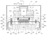
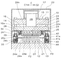
本発明の実施形態について図1ないし図3を参照して説明する。図1は、本実施形態の光ディスク基板転写成形装置の断面図である。図2は、本実施形態の光ディスク基板転写成形装置の図1におけるA―A線における断面図である。図3は、本実施形態の光ディスク基板転写成形装置の作動説明図である。 An embodiment of the present invention will be described with reference to FIGS. FIG. 1 is a cross-sectional view of the optical disk substrate transfer molding apparatus of this embodiment. 2 is a cross-sectional view taken along the line AA in FIG. 1 of the optical disk substrate transfer molding apparatus according to the present embodiment. FIG. 3 is an operation explanatory view of the optical disk substrate transfer molding apparatus of the present embodiment.
なお本実施形態では、直径が120mm、中心孔径12mm、板厚寸法が0.1mmの、ブルーレイ用ディスク(光ディスク基板)を成形する光ディスク基板転写成形装置を例に説明する。図1、図2に示されるように光ディスク基板転写成形装置のプレス成形装置11は、ベッド12に第一の型である下型13が固着されている。またベッド12の四隅近傍にはタイバー14がそれぞれ立設され、タイバー14の上部には上盤15が固着されている。そして前記タイバー14には可動盤16が摺動可能に取付けられ、前記可動盤16には第二の型である上型19が固着されている。また上盤15に固着された加圧機構である加圧シリンダ17のピストン18が前記可動盤16に固着され、可動盤16は昇降可能となっている。よってプレス成形装置11は、加圧シリンダ17の駆動により下型13に対して上型19が昇降移動され、両金型の間で後述する帯状樹脂フィルムF(以下単にフィルムFと省略す)を加熱・加圧可能となっている。また光ディスク基板転写成形装置は、真空チャンバ20と図示しない真空吸引装置を備えている。そして前記プレス成形装置11と、後述する供給機構31、テンション機構32,33,34、および搬送機構35等は、前記真空チャンバ20の中に収納されている。
In this embodiment, an optical disk substrate transfer molding apparatus for molding a Blu-ray disc (optical disk substrate) having a diameter of 120 mm, a center hole diameter of 12 mm, and a plate thickness of 0.1 mm will be described as an example. As shown in FIGS. 1 and 2, in a
プレス成形装置11の下型13は、上面が平坦なステンレス板からなる冷却盤21からなる。冷却盤21は、内部に複数の温調用媒体通路22が配設され、図示しない温調器から温調用媒体が流通されることにより、所定の温度に制御されるようになっている。一方上型19は、可動盤16に固着される加圧盤23、該加圧盤23に対して裏面24aが当接および離隔可能に設けられた転写板24、および該転写板24を前記加圧盤23に当接・離隔させる転写板移動機構25等からなっている。上型19の加圧盤23は、下型13の冷却盤21と同様に、内部に複数の温調用媒体通路26が配設され、図示しない温調器から温調用媒体が流通されることにより、所定の温度に制御されるようになっている。そして加圧盤23の下面には、平坦な断熱板27が貼付けられている。断熱板27は後述する転写板24に通電した際に転写板24と加圧盤23を絶縁する目的も兼用しており、本実施形態ではセラミック板からなっている。ただし加圧盤23の下面に断熱板27の代わりに断熱作用を有さずに絶縁板を貼付け、加熱・加圧時に、転写板24が温度調整された加圧盤23からも冷却されるようにしてもよい。
The
また図2に示されるように、可動盤16の下面16aであって加圧盤23が固着された部分の外側にはバネ28とホルダ29からなる転写板移動機構25がそれぞれ取付けられている。転写板移動機構25のバネ28は、可動盤16の下面16aの一側と他側にそれぞれ複数本が固着され、バネ28の先端は転写板24の端部裏面24bに固着されている。また可動盤16の下面16aの前記バネ28が取付けられた部分の外側部分には、ホルダ29がそれぞれ取付けられている。前記ホルダ29の先端側は、内側に向けて屈曲しており、屈曲した部分の可動盤16の下面16a側には、当接面29aとなっている。そして前記当接面29aに対して、バネ28に付勢された転写板24の端部表面24cが当接され、転写板24の下方への移動が規制されるようになっている。なお転写板24におけるバネ28と固着される端部裏面24bやホルダ29の当接面29aと当接される端部表面24cは絶縁材が貼着されている。前記構成により転写板24は、可動盤16の型開位置停止時、型開動作時、および型閉動作時には加圧盤23から離隔し、加熱・加圧時には転写板24の裏面24aと加圧盤23の断熱板27が当接される。また前記転写板移動機構25の例としてシリンダ等のアクチュエータにより転写板24を加圧盤23に対して当接および離隔移動可能としてもよい。
As shown in FIG. 2, a transfer
転写板24は板厚が3mm、長手方向の長さ150mm、幅150mmの略矩形の通電により発熱するステンレス板24dと、該ステンレス板24dの表面に貼付けられたスタンパ24eとから構成されている。そしてステンレス板24dの長手方向の一側端部と他側端部には端子部24fがそれぞれに複数設けられ、端子部24fには図示しない直流電源と電線30によって接続され、ステンレス板24dに通電可能となっている。ステンレス板24dが略矩形であるのは、ステンレス板24dの一側と他側の向い合う端子部24f同士の間隔をそれぞれ略等しくすることができ、ステンレス板24dとスタンパ24eを均等に加熱できるためである。そして前記の転写板24や端子部24f、電線30、および直流電源等から転写板24の加熱機構(抵抗加熱機構)が構成されている。なお抵抗加熱機構の電源は、交流電源を用いてもよい。
The
またスタンパ24eについては厚さが0.3mm、直径が120mmであり、中心孔が形成されていないニッケル製スタンパ24eが使用される。スタンパ24eは、ブルーレイディスク用のトラックピッチ0.32μmの信号ピットを転写可能な微細な凹凸パターンが形成された転写面24gを有している。なお転写板24におけるスタンパ24eの取付けは、ステンレス板24dに貼付けされたもの以外に、爪によりステンレス板24dに保持されたものや、スタンパ24eと抵抗加熱板が一体に構成されたものでもよい。また転写板24におけるスタンパ24eの枚数は1枚に限定されず、同時に複数枚の光ディスク基板を転写成形するようにしてもよい。
As for the
なお本発明のプレス成形装置11において、前記ステンレス板24dの板厚は1mmないし5mmが望ましく、熱容量が小さく抵抗加熱により急速に温度上昇可能なものが用いられる。なお転写板24の加熱機構については、抵抗加熱機構に限定されず、誘導加熱機構を用いてもよく、その場合の転写板24は略円形に設けられる。またプレス成形装置11においては、スタンパを有する第二の型の方が型温が高いので、フィルムFへの影響を考えると第二の型を上型とした方が望ましいが、前記に限定されない。更には加圧機構、可動盤をフィルムFの下方に設け、第一の型である下型を可動盤に固着して、前記下型を第二の型である上型に向けて上昇させ、フィルムFに加熱・加圧を行なうものでもよい。第一の型にも転写板を設け、第一の型と第二の型の転写板はそれぞれ加圧盤によって冷却されるようにしてもよい。更にはまた本発明において真空チャンバ20は必須のものではない。
In the
次に前記プレス成形装置11にフィルムFを供給する供給機構31、フィルムFに張りを与えるテンション機構32,33,34、およびフィルムFを搬送する搬送機構35等について説明する。図1に示されるように、プレス成形装置11の搬入側(一側)にはフィルムFを供給する供給機構31の供給用ローラ36が配設されている。供給用ローラ36には、未使用フィルムロールF1が回転可能に取付けられる。また供給用ローラ36には、前記未使用フィルムロールF1が回転してフィルムFが繰り出される際に、慣性により所定以上回転しないように回転停止機構が取付けられている。更に前記供給用ローラ36の上方には、高さ調整用ローラ37が配設され、未使用フィルムロールF1の残量にかかわらず、同一高さでフィルムFがプレス成形装置11に向けて供給可能となっている。
Next, a
また図1に示されるように、プレス成形装置11の搬入側の成形位置近傍にはテンション機構32の搬入側ローラ38,38が、フィルムFの搬入・搬出方向Bと直交する方向Cに軸芯38aが向けられて配設されている。そして前記搬入側ローラ38,38は、フィルムFの上下面に圧接され、フィルムFの搬送により回転されるようになっている。またプレス成形装置11の搬出側(他側)の成形位置近傍には、テンション機構34の搬出側ローラ39,39が、搬入・搬出方向Bと直交する方向Cに軸芯39a,39aが向けられて配設されている。そして搬出側ローラ39,39は、フィルムFの把持用エアシリンダ40,40によってフィルムFの上下面に対して圧接および離隔移動可能に設けられている。これらの搬入側ローラ38,38および搬出側ローラ39,39のローラは、弾性ゴムからなっている。そしてテンション機構34には、搬出側ローラ39,39を回転させる図示しないモータが配設されている。またテンション機構34はモータを使用せずに、フィルムFを搬出方向に向けて引っ張るためのエアシリンダを取付けてもよい。そしてこれらの搬入側ローラ38,38、搬出側ローラ39,39から加熱・加圧成形開始時までに搬入・搬出方向Bの張りが与えられる。なおテンション機構32,34の少なくとも一方については、ローラを使用せず、フィルムFの上下面を上下から把持および開放する把持機構としてもよい。そしてその場合は、テンション機構32,34には、フィルムFを搬入方向B2および搬出方向B1に向けて引っ張るためのエアシリンダがそれぞれ取付けられる。なおテンション機構32,34は、プレス成形装置11の成形位置近傍に設置されることにより転写成形時のフィルムFの張りを良好にする作用を有するが、本発明には必須のものではない。そしてテンション機構32,34を設けない場合は、供給用ローラ36と後述する巻取用ローラ45が、テンション機構32,34の機能を兼用し、転写成形時のフィルムFに張りを与える。
Further, as shown in FIG. 1, in the vicinity of the forming position on the carry-in side of the press-forming
また図2に示されるように、プレス成形装置11のベッド12の上面12aにおける下型13が固着された部分の両側の成形位置近傍には、テンション機構33,33が配設されている。テンション機構33には、フィルムFの転写がされない両側部分F3を上下方向から挟むための把持部41a,41bが設けられている。把持部41a,41bの搬入・搬出方向Bの長さは、下型13の長さとほぼ等しい長さとなっており、把持部41a、41bの把持面には弾性ゴムが貼付けられている。またテンション機構33には、前記把持部41aを把持部41bに向けて進退移動させてフィルムFを把持および開放するための把持用エアシリンダ42と、把持したフィルムFを搬入・搬出方向Bと直交する方向Cのプレス成形装置11から外方向C1,C2に向けて引っ張るための引張用エアシリンダ43が設けられている。またテンション機構33には、加熱・加圧時にフィルムFが、上型19によって下型13に向けて押圧される際に、テンション機構33の高さ調節する機構としてバネ44が取付けられている。なおテンション機構33,33のエアシリンダ42は一方のみに設けられたものでもよく、またテンション機構33,33は、フィルムFに更に多方向へ引張るものでもよい。
As shown in FIG. 2,
また図1に示されるように、プレス成形装置11の搬出側には、フィルムFを搬送する搬送機構35が配設されている。搬送機構35は、転写成形の終了したフィルムFを巻取るための巻取用ローラ45が搬入・搬出方向Bと直交する方向Cに向けて配設されている。そして前記巻取用ローラ45は、巻取られたフィルムF4の量により、巻取時の回転数とトルクが調整されるようになっている。また前記巻取用ローラ45の上方には高さ調整用ローラ46が配設されている。なお前記搬送機構35については、転写成形の終了したフィルムFの転写部分F2以外の部分を上下から挟んで、チェーン等を駆動させて、搬出方向B1に向けて引っ張るものであってもよい。
As shown in FIG. 1, a
次に本実施形態の光ディスク基板の転写成形方法について図1ないし図3を参照して説明する。本実施形態では、フィルムFは、厚さ70μm、ガラス転移温度145℃のポリカーボネートフィルムに、厚さ30μmのポリエチレンテレフタレートフィルムが積層されたものが使用される。そしてフィルムFにおけるポリエチレンテレフタレートフィルムは、転写成形されたポリカーボネートフィルムが巻取用ローラ45に巻取られる際に、ポリカーボネートフィルムの転写面を保護する役割をする。なお本発明において樹脂フィルムとは、一または複数種の樹脂からなり、全体の厚さが50μmないし300μmのものを指し、一般には可撓性を有するが、硬質のものでもよい。また本実施形態で光ディスク基板の転写成形されるフィルムFの樹脂については熱により変形して転写成形可能であり、ブルーレイの読取りに使用される短波長のレーザーを透過可能なものであればよい。光学製品の転写成形に使用されるフィルムFの一例としては前記ポリカーボネートの他、アクリル、ポリエステル、ポリスチレン、ポリ塩化ビニル、ポリエチレンテレフタレート等が使用される。
Next, an optical disk substrate transfer molding method according to this embodiment will be described with reference to FIGS. In this embodiment, the film F is a laminate of a polyethylene terephthalate film having a thickness of 30 μm and a polycarbonate film having a thickness of 70 μm and a glass transition temperature of 145 ° C. The polyethylene terephthalate film in the film F serves to protect the transfer surface of the polycarbonate film when the transfer-molded polycarbonate film is taken up by the take-up
本実施形態では光ディスク基板転写成形装置の真空チャンバ20の内部は、一定の真空状態に保たれている。まず図3に示されるように、プレス成形装置11においてフィルムFに加熱・加圧がなされ転写成形が完了して型開され、フィルムFに与えられている張りが解除される。すると、搬送機構35の巻取用ローラ45の回転により、フィルムFが搬出方向B1に向けて引っ張られ、転写成形が終了したフィルムFがプレス成形装置11から搬出される。またそれと同時に次に転写成形されるフィルムFがポリカーボネートフィルムを上面にしてプレス成形装置11に搬入される。次にテンション機構34の把持用エアシリンダ40,40が作動され、搬出側ローラ39,39がフィルムFに圧接される。その後テンション機構34の図示しないモータが作動されて搬出側ローラ39,39が回転され、フィルムFが搬出方向B1に向けて引っ張られる。またほぼ同時にテンション機構33の把持用エアシリンダ42が作動されてフィルムFが把持され、更に引張用エアシリンダ43が作動され、フィルムFが搬送・搬出方向Bと直交しする方向Cにおけるプレス成形装置11から外方向C1,C2に向けてそれぞれ引っ張られる。そしてフィルムFは縦方向と横方向に向けてそれぞれ張りが与えられ、プレス成形装置11による加圧・加熱開始の準備が完了する。前記のフィルムFが搬送されてからフィルムFが引っ張りが与えられるまでの間、フィルムFは上型19の転写板24と下型13の冷却盤21のいずれからも離隔した状態にある。なお本実施形態において、フィルムFの搬送に要する時間は2秒であり、フィルムFに張りを与えるのに要する時間は1秒である。
In the present embodiment, the inside of the
この際プレス成形装置11の下型13の冷却盤21は、60℃に温調されている。なお冷却盤21の温度は転写されるポリカーボネートのガラス転移温度より30℃ないし105℃低いことが望ましく、更には前記ガラス転移温度より60℃ないし95℃低いことがより望ましい。また上型19の転写板24は、前回のプレス成形完了後に加圧盤23から離隔されるのとほぼ同時に、2V、4000Aの電流が通電開始され、抵抗加熱により200℃に昇温されている。なお転写板24の温度はフィルムFの転写されるポリカーボネートのガラス転移温度145℃より20℃ないし80℃高い温度が望ましく、更には前記ガラス転移温度より40℃ないし70℃高い温度であることがより望ましい。
At this time, the cooling
そして次に加圧シリンダ17の作動により型閉が開始され、上型19が下降してフィルムFの転写部分F2に転写板24が当接する。そしてなおも上型19が下降されると、転写板24によりフィルムFの裏面側のポリエチレンテレフタレートフィルムが下型13の冷却盤21に押付けられる。それと並行して転写板移動機構25のバネ28が収縮され、転写板24の裏面24aと加圧盤23の断熱板27が当接される。そして転写板24が加圧盤23に当接され、フィルムFに加圧シリンダ17による加圧が開始されるのとほぼ同時に、転写板24への通電を中止する。この加熱・加圧時の転写板24のステンレス板24dは厚さが3mmであり冷却盤21よりも熱容量が小さいので、転写板24は、フィルムFを介して冷却盤21によって容易に熱を奪われ温度が低下する。そしてプレス成形装置11によるフィルムFへの加熱・加圧時の間に転写板24の温度は、転写成形されるポリカーボネートフィルムのガラス転移温度以下である120℃程度に低下される。なお加熱・加圧終了時の転写板24の温度は、フィルムFのガラス転移温度以下であってガラス転移温度より40℃低い温度までの範囲が望ましい。そしてこの加熱・加圧時の転写板24からフィルムFに対して及ぼされる圧力は、8MPaで、4秒の加圧を行なう。なお前記圧力については、4MPaないし12MPaが望ましく、加圧時間は2秒ないし7秒が望ましい。なお本発明において、転写板24の冷却は、冷却盤21および加圧盤23の少なくとも一方をフィルムFのガラス転移温度よりも30℃ないし100℃低い温度に温度調整し、フィルムFの加熱・加圧時に転写板24の温度をフィルムFのガラス転移温度以下に下降させるものであればよい。
Then, the closing of the mold is started by the operation of the
そして加熱した転写板24による加熱・加圧(転写成形)が完了すると、型開が行なわれる。この際の加熱・加圧終了時の転写板24の温度は、前記したように、転写されるフィルムFのガラス転移温度以下となっているので、フィルムFから転写板24のスタンパ24eを離型する際の離型が良好にできる。そしてフィルムFからスタンパ24eが離型されてからもフィルムFはテンション機構32,33,34によって約1秒保持され、その後保持が解消される。よって本発明では、加熱・加圧開始時から加熱・加圧終了後所定時間が経過するまでフィルムFに張りが与えられた状態で転写成形が行なわれるので、フィルムFの表面と裏面の材質や温度が異なっていても、転写不良、反り、収縮、および皺の少なくとも一つが発生することがない。その後テンション機構33,34によるフィルムFの張りが解除され、上記したように転写成形が終了したフィルムFが再びプレス成形装置11から搬出される。なお転写成形および離型後のフィルムFに張りを与えた状態で、冷却エア等を吹付け、冷却を更に促進させるようにしてもよい。
When the heating and pressurization (transfer molding) by the
本実施形態では、転写成形が終了したフィルムFは一度巻取用ローラ45によって転写部分F2がポリエチレンテレフタレートフィルムと重ねられるように巻取られ、別工程で打抜きや他の板厚寸法の厚い光ディスク基板との貼合せが行なわれる。ただし本光ディスク基板転写成形装置において巻取用ローラ45を設けずに、打抜き等を行なうようにしてもよい。
In this embodiment, the film F on which transfer molding has been completed is once wound up by the winding
また本発明については、一々列挙はしないが、上記した実施形態のものに限定されず、当業者が本発明の趣旨を踏まえて変更を加えたものについても、適用されることは言うまでもない。一例として本実施形態では光ディスク基板の転写成形について説明したが、本発明は、フィルムFを用いた導光板、光拡散板、レンズ等の光学製品全般の転写成形に使用することができる。そしてフィルムFについては、連続した帯状樹脂フィルムFに限定されず、1回の転写成形分づつに切断されたフィルムを使用して転写成形を行なうものでもよい。 The present invention is not enumerated one by one, but is not limited to the above-described embodiment, and it goes without saying that the present invention can be applied to those modified by a person skilled in the art based on the gist of the present invention. As an example, in this embodiment, transfer molding of an optical disk substrate has been described. However, the present invention can be used for transfer molding of optical products such as a light guide plate, a light diffusion plate, and a lens using the film F. And about the film F, it is not limited to the continuous strip-shaped resin film F, You may transfer-mold using the film cut | disconnected for every transfer molding.
11 プレス成形装置
12 ベッド
13 下型
14 タイバー
15 上盤
16 可動盤
16a 下面
17 加圧シリンダ
18 ピストン
19 上型
20 真空チャンバ
21 冷却盤
22,26 温調用媒体通路
23 加圧盤
24 転写板
24a 裏面
24b 端部裏面
24c 端部表面
24d ステンレス板
24e スタンパ
24f 端子部
24g 転写面
25 転写板移動機構
27 断熱板
28,44 バネ
29 ホルダ
30 電線
31 供給機構
32,33,34 テンション機構
35 搬送機構
36 供給用ローラ
37,46 高さ調整用ローラ
38 搬入側ローラ
38a,39a 軸芯
39 搬出側ローラ
40,42 把持用エアシリンダ
41a,41b 把持部
43 引張用エアシリンダ
45 巻取用ローラ
B 搬入・搬出方向
B1 搬出方向
B2 搬入方向
C 直交する方向
C1,C2 外方向
F 帯状樹脂フィルム
F1 未使用フィルムロール
F2 転写部分
F3 両側部分
F4 巻取られたフィルム
DESCRIPTION OF
Claims (6)
冷却盤を有する第一の型と、
加圧盤に対して裏面が当接および離隔可能に設けられ前記樹脂フィルムに転写を行なう前記転写板とが設けられた第二の型と、
前記第一の型と前記第二の型との間で前記樹脂フィルムを加圧する加圧機構と、
前記樹脂フィルムに張りを与えるテンション機構と、
が設けられたことを特徴とする光学製品の転写成形装置。 In a transfer molding apparatus for optical products that performs transfer molding by pressing a heated transfer plate having a fine uneven pattern against a resin film,
A first mold having a cooling plate;
A second mold provided with the transfer plate that is provided so that the back surface can be brought into contact with and separated from the pressure plate and that transfers to the resin film;
A pressurizing mechanism for pressurizing the resin film between the first mold and the second mold;
A tension mechanism for tensioning the resin film;
A transfer molding apparatus for optical products, comprising:
前記テンション機構は少なくとも前記帯状樹脂フィルムの搬入・搬出方向と搬入・搬出方向と直交する方向に前記帯状樹脂フィルムを引っ張るように設けられている請求項1に記載の光学製品の転写成形装置。 The resin film is composed of a belt-shaped resin film, and a transport mechanism for transporting the belt-shaped resin film is provided.
2. The optical product transfer molding apparatus according to claim 1, wherein the tension mechanism is provided so as to pull the belt-like resin film at least in a direction orthogonal to the carry-in / carry-out direction of the belt-like resin film.
光ディスク基板用の信号ピットを転写可能なスタンパが取付けられたものである請求項1または請求項2に記載の光学製品の転写成形装置。 The transfer plate is a stainless steel plate having a thickness of 1 mm to 5 mm that generates heat when energized.
The optical product transfer molding apparatus according to claim 1 or 2, wherein a stamper capable of transferring signal pits for an optical disk substrate is attached.
第一の型における冷却盤および第二の型における加圧盤の少なくとも一方を前記樹脂フィルムのガラス転移温度よりも30℃ないし100℃低い温度に温度調整し、
第二の型における前記転写板の温度を前記樹脂フィルムのガラス転移温度よりも20℃ないし80℃高い温度に加熱し、
前記第一の型と第二の型の間で前記樹脂フィルムに張りを与えた状態で、
前記転写板の温度を前記樹脂フィルムのガラス転移温度以下に下降させつつ加圧し、
前記樹脂フィルムに微細な凹凸パターンの転写を行なうことを特徴とする光学製品の転写成形方法。 In a transfer molding method of an optical product that performs transfer molding by pressing a heated transfer plate having a fine uneven pattern against a resin film,
At least one of the cooling plate in the first mold and the pressure plate in the second mold is adjusted to a temperature 30 ° C. to 100 ° C. lower than the glass transition temperature of the resin film,
The temperature of the transfer plate in the second mold is heated to a temperature 20 to 80 ° C. higher than the glass transition temperature of the resin film,
In a state where tension is given to the resin film between the first mold and the second mold,
Pressurizing while lowering the temperature of the transfer plate below the glass transition temperature of the resin film,
A transfer molding method of an optical product, wherein a fine uneven pattern is transferred to the resin film.
加圧時間は2秒ないし7秒である請求項4に記載の光学製品の転写成形方法。 The pressure applied to the resin film by the transfer plate during pressurization is 4 MPa to 12 MPa,
5. The optical product transfer molding method according to claim 4, wherein the pressing time is 2 seconds to 7 seconds.
Priority Applications (1)
| Application Number | Priority Date | Filing Date | Title |
|---|---|---|---|
| JP2004005293A JP2005199455A (en) | 2004-01-13 | 2004-01-13 | Transfer molding machine for optical product and transfer molding method using it |
Applications Claiming Priority (1)
| Application Number | Priority Date | Filing Date | Title |
|---|---|---|---|
| JP2004005293A JP2005199455A (en) | 2004-01-13 | 2004-01-13 | Transfer molding machine for optical product and transfer molding method using it |
Publications (1)
| Publication Number | Publication Date |
|---|---|
| JP2005199455A true JP2005199455A (en) | 2005-07-28 |
Family
ID=34819667
Family Applications (1)
| Application Number | Title | Priority Date | Filing Date |
|---|---|---|---|
| JP2004005293A Pending JP2005199455A (en) | 2004-01-13 | 2004-01-13 | Transfer molding machine for optical product and transfer molding method using it |
Country Status (1)
| Country | Link |
|---|---|
| JP (1) | JP2005199455A (en) |
Cited By (12)
| Publication number | Priority date | Publication date | Assignee | Title |
|---|---|---|---|---|
| EP1787788A2 (en) * | 2005-11-22 | 2007-05-23 | Konica Minolta Holdings, Inc. | Imprinting apparatus and method |
| WO2007089012A1 (en) * | 2006-01-31 | 2007-08-09 | Canon Kabushiki Kaisha | Method for manufacturing electrophotographic photoreceptor |
| WO2008047540A1 (en) | 2006-09-27 | 2008-04-24 | Toray Industries, Inc. | Intermittent film forming system and intermittent film forming method |
| JP2008120073A (en) * | 2006-10-11 | 2008-05-29 | Toray Ind Inc | Manufacturing process and apparatus of detailed configuration transfer sheet |
| JP2009113443A (en) * | 2007-11-09 | 2009-05-28 | Toray Ind Inc | Method for molding transfer sheet of fine shape, and apparatus for molding transfer sheet of fine shape |
| WO2009113453A1 (en) | 2008-03-14 | 2009-09-17 | 東レ株式会社 | Production method and production device of film having fine irregular pattern on surface |
| JP2009220562A (en) * | 2008-02-22 | 2009-10-01 | Toray Ind Inc | Apparatus and method for manufacturing microscopic transfer sheet |
| JP2010058301A (en) * | 2008-09-02 | 2010-03-18 | Isamu Kuremoto | Embossing method for leather-like sheet and leather-like sheet obtained by the same |
| JP2012020522A (en) * | 2010-07-15 | 2012-02-02 | Maruzen Petrochem Co Ltd | Thermal nanoimprinting method |
| KR101422391B1 (en) | 2012-11-05 | 2014-07-22 | 오므론 가부시키가이샤 | Mold structure, transcription molding device, transcription molding method, optical member, surface light source device, lcd device and mobile device |
| KR101422390B1 (en) | 2012-11-05 | 2014-07-22 | 오므론 가부시키가이샤 | Transfer molding method and transfer molding apparatus |
| TWI510375B (en) * | 2012-11-05 | 2015-12-01 | Omron Tateisi Electronics Co | Mold structure, transfer formation device and transfer formation method |
-
2004
- 2004-01-13 JP JP2004005293A patent/JP2005199455A/en active Pending
Cited By (27)
| Publication number | Priority date | Publication date | Assignee | Title |
|---|---|---|---|---|
| EP1787788A2 (en) * | 2005-11-22 | 2007-05-23 | Konica Minolta Holdings, Inc. | Imprinting apparatus and method |
| EP1787788A3 (en) * | 2005-11-22 | 2009-11-11 | Konica Minolta Holdings, Inc. | Imprinting apparatus and method |
| US7645411B2 (en) | 2005-11-22 | 2010-01-12 | Konica Minolta Holdings, Inc. | Imprinting apparatus and method |
| WO2007089012A1 (en) * | 2006-01-31 | 2007-08-09 | Canon Kabushiki Kaisha | Method for manufacturing electrophotographic photoreceptor |
| US7622238B2 (en) | 2006-01-31 | 2009-11-24 | Canon Kabushiki Kaisha | Process for producing electrophotographic photosensitive member |
| WO2008047540A1 (en) | 2006-09-27 | 2008-04-24 | Toray Industries, Inc. | Intermittent film forming system and intermittent film forming method |
| KR101400811B1 (en) | 2006-09-27 | 2014-05-29 | 도레이 카부시키가이샤 | Intermittent film forming system and intermittent film forming method |
| US8647097B2 (en) | 2006-09-27 | 2014-02-11 | Toray Industries, Inc. | Intermittent film forming system and intermittent film forming method |
| US8231372B2 (en) | 2006-09-27 | 2012-07-31 | Toray Industries, Inc. | Intermittent film forming system and intermittent film forming method |
| JP2008120073A (en) * | 2006-10-11 | 2008-05-29 | Toray Ind Inc | Manufacturing process and apparatus of detailed configuration transfer sheet |
| JP2009113443A (en) * | 2007-11-09 | 2009-05-28 | Toray Ind Inc | Method for molding transfer sheet of fine shape, and apparatus for molding transfer sheet of fine shape |
| JP2009220562A (en) * | 2008-02-22 | 2009-10-01 | Toray Ind Inc | Apparatus and method for manufacturing microscopic transfer sheet |
| JP5482202B2 (en) * | 2008-03-14 | 2014-05-07 | 東レ株式会社 | Method and apparatus for producing film having fine uneven pattern on surface |
| CN101970210A (en) * | 2008-03-14 | 2011-02-09 | 东丽株式会社 | Production method and production device of film having fine irregular pattern on surface |
| KR101558956B1 (en) | 2008-03-14 | 2015-10-08 | 도레이 카부시키가이샤 | Production method and production device of film having fine irregular pattern on surface |
| WO2009113453A1 (en) | 2008-03-14 | 2009-09-17 | 東レ株式会社 | Production method and production device of film having fine irregular pattern on surface |
| EP2263858B1 (en) * | 2008-03-14 | 2018-11-07 | Toray Industries, Inc. | Production method and production device of film having fine irregular pattern on surface |
| US9840039B2 (en) | 2008-03-14 | 2017-12-12 | Toray Industries, Inc. | Production method and production device of film having fine irregular pattern on surface |
| US8911655B2 (en) | 2008-03-14 | 2014-12-16 | Toray Industries, Inc. | Production method and production device of film having fine irregular pattern on surface |
| TWI495556B (en) * | 2008-03-14 | 2015-08-11 | Toray Industries | Method and apparatus for producing film having fine uneven pattern surface |
| JP2010058301A (en) * | 2008-09-02 | 2010-03-18 | Isamu Kuremoto | Embossing method for leather-like sheet and leather-like sheet obtained by the same |
| JP2012020522A (en) * | 2010-07-15 | 2012-02-02 | Maruzen Petrochem Co Ltd | Thermal nanoimprinting method |
| TWI510376B (en) * | 2012-11-05 | 2015-12-01 | Omron Tateisi Electronics Co | Transfer formation method and transfer formation device |
| TWI510375B (en) * | 2012-11-05 | 2015-12-01 | Omron Tateisi Electronics Co | Mold structure, transfer formation device and transfer formation method |
| US9452572B2 (en) | 2012-11-05 | 2016-09-27 | Omron Corporation | Transfer molding method and transfer molding apparatus |
| KR101422390B1 (en) | 2012-11-05 | 2014-07-22 | 오므론 가부시키가이샤 | Transfer molding method and transfer molding apparatus |
| KR101422391B1 (en) | 2012-11-05 | 2014-07-22 | 오므론 가부시키가이샤 | Mold structure, transcription molding device, transcription molding method, optical member, surface light source device, lcd device and mobile device |
Similar Documents
| Publication | Publication Date | Title |
|---|---|---|
| JP3974118B2 (en) | Optical product transfer molding apparatus and transfer molding method | |
| TWI495556B (en) | Method and apparatus for producing film having fine uneven pattern surface | |
| JP2005199455A (en) | Transfer molding machine for optical product and transfer molding method using it | |
| TWI331557B (en) | Laminate molding apparatus and laminate molding process | |
| WO2012070546A1 (en) | Transfer device and method for producing resin pattern | |
| JP3546333B2 (en) | Vacuum laminating apparatus and vacuum laminating method | |
| KR20160106485A (en) | Imprinting device | |
| JP5077764B2 (en) | Imprint method and apparatus | |
| JPWO2008149801A1 (en) | Press device and press device system | |
| CN112339412B (en) | Microstructure transfer device and microstructure transfer method | |
| JP2004082437A (en) | Apparatus for molding light guiding plate and method for molding light guiding plate | |
| JP4585321B2 (en) | Resin molding apparatus and resin molding method | |
| JP2011136461A (en) | Embossing apparatus | |
| JP4878021B2 (en) | Decorative sheet feeding apparatus and method for producing simultaneously molded decorative molded product | |
| JPS58132529A (en) | Simultaneous injection and molding process | |
| JP2005053214A (en) | Shaping apparatus of resin formed article and shaping method for it | |
| JP5233106B2 (en) | Lens sheet manufacturing method and manufacturing apparatus | |
| JP2005231226A (en) | Apparatus for molding resin plate | |
| JP6104691B2 (en) | Nanoimprint method and apparatus therefor | |
| JP2006035573A (en) | Apparatus and method for molding resin molding | |
| JP2011093113A (en) | Device and method for manufacturing laminated substrate | |
| JPH11129431A (en) | Lamination device and laminating method | |
| JP2000309033A (en) | Method and apparatus for injection molding simultaneous in-mold decoration | |
| JP5645225B2 (en) | Lamination molding system and lamination molding method | |
| JP2010167594A (en) | Molding method and molding system for thin plate |
Legal Events
| Date | Code | Title | Description |
|---|---|---|---|
| A621 | Written request for application examination |
Free format text: JAPANESE INTERMEDIATE CODE: A621 Effective date: 20050831 |
|
| A977 | Report on retrieval |
Free format text: JAPANESE INTERMEDIATE CODE: A971007 Effective date: 20070731 |
|
| A131 | Notification of reasons for refusal |
Free format text: JAPANESE INTERMEDIATE CODE: A131 Effective date: 20070821 |
|
| A521 | Written amendment |
Free format text: JAPANESE INTERMEDIATE CODE: A523 Effective date: 20070924 |
|
| A02 | Decision of refusal |
Free format text: JAPANESE INTERMEDIATE CODE: A02 Effective date: 20081021 |