JP2005195106A - Continuously variable transmission - Google Patents

Continuously variable transmission Download PDF

Info

Publication number
JP2005195106A
JP2005195106A JP2004002762A JP2004002762A JP2005195106A JP 2005195106 A JP2005195106 A JP 2005195106A JP 2004002762 A JP2004002762 A JP 2004002762A JP 2004002762 A JP2004002762 A JP 2004002762A JP 2005195106 A JP2005195106 A JP 2005195106A
Authority
JP
Japan
Prior art keywords
speed clutch
switching valve
continuously variable
variable transmission
pressure
Prior art date
Legal status (The legal status is an assumption and is not a legal conclusion. Google has not performed a legal analysis and makes no representation as to the accuracy of the status listed.)
Pending
Application number
JP2004002762A
Other languages
Japanese (ja)
Other versions
JP2005195106A5 (en
Inventor
Toshiro Toyoda
俊郎 豊田
Eiji Inoue
英司 井上
Current Assignee (The listed assignees may be inaccurate. Google has not performed a legal analysis and makes no representation or warranty as to the accuracy of the list.)
NSK Ltd
Original Assignee
NSK Ltd
Priority date (The priority date is an assumption and is not a legal conclusion. Google has not performed a legal analysis and makes no representation as to the accuracy of the date listed.)
Filing date
Publication date
Application filed by NSK Ltd filed Critical NSK Ltd
Priority to JP2004002762A priority Critical patent/JP2005195106A/en
Publication of JP2005195106A publication Critical patent/JP2005195106A/en
Publication of JP2005195106A5 publication Critical patent/JP2005195106A5/ja
Pending legal-status Critical Current

Links

Images

Abstract

<P>PROBLEM TO BE SOLVED: To surely disconnect a high-speed clutch even if oil pressure discharge quantity from a pressurizing pump is small immediately before and after starting after switching a manual selector valve 32a to a range R for reversing. <P>SOLUTION: The manual selector valve 32a is provided with an upstream side discharge port 70 communicated with a high-speed clutch oil pressure chamber attached to the high-speed clutch and a downstream side discharge port 71 communicated with an oil reservoir 30. In the condition wherein the manual selector valve 32a is switched to the range R, both the ports 70 and 71 are communicated with each other to discharge the oil pressure inside the high-speed clutch oil chamber to disconnect the high-speed clutch. With this structure, the high-speed clutch is surely disconnected to prevent driving force applying in the travelling direction even in a short time. <P>COPYRIGHT: (C)2005,JPO&NCIPI

Description

この発明は、車両(自動車)用自動変速装置として利用する、トロイダル型無段変速機と遊星歯車式変速機とを複数のクラッチを介して組み合わせた無段変速装置の改良に関する。具体的には、車両を後退させようとした場合に、短時間とは言え、前方に発進する事を確実に防止できる構造を実現するものである。   The present invention relates to an improvement of a continuously variable transmission that is used as an automatic transmission for a vehicle (automobile) and combines a toroidal continuously variable transmission and a planetary gear transmission via a plurality of clutches. Specifically, it is possible to realize a structure that can reliably prevent the vehicle from starting forward although it is a short time when the vehicle is to be moved backward.

自動車用自動変速装置として、図5に示す様なトロイダル型無段変速機を使用する事が研究され、一部で実施されている。このトロイダル型無段変速機は、ダブルキャビティ型と呼ばれるもので、入力軸1の両端部周囲に入力側ディスク2、2を、ボールスプライン3、3を介して支持している。従ってこれら両入力側ディスク2、2は、互いに同心に、且つ、同期した回転を自在に支持されている。又、上記入力軸1の中間部周囲に出力歯車4を、この入力軸1に対する相対回転を自在として支持している。そして、この出力歯車4の中心部に設けた円筒部の両端部に出力側ディスク5、5を、それぞれスプライン係合させている。従ってこれら両出力側ディスク5、5は、上記出力歯車4と共に、同期して回転する。   The use of a toroidal-type continuously variable transmission as shown in FIG. 5 as an automatic transmission for automobiles has been studied and implemented in part. This toroidal type continuously variable transmission is called a double cavity type, and supports input-side disks 2 and 2 around both ends of the input shaft 1 via ball splines 3 and 3. Therefore, both the input side disks 2 and 2 are supported concentrically and freely in a synchronized manner. An output gear 4 is supported around the intermediate portion of the input shaft 1 so as to be freely rotatable relative to the input shaft 1. The output side disks 5 and 5 are respectively spline-engaged with both ends of a cylindrical portion provided at the center of the output gear 4. Accordingly, both the output side disks 5 and 5 rotate in synchronism with the output gear 4.

又、上記各入力側ディスク2、2と上記各出力側ディスク5、5との間には、それぞれ複数個ずつ(通常2〜3個ずつ)のパワーローラ6、6を挟持している。これら各パワーローラ6、6は、それぞれトラニオン7、7の内側面に、支持軸8、8及び複数の転がり軸受を介して、回転自在に支持されている。上記各トラニオン7、7は、それぞれの長さ方向(図5の表裏方向)両端部に、これら各トラニオン7、7毎に互いに同心に設けられた枢軸を中心として揺動変位自在である。これら各トラニオン7、7を傾斜させる動作は、周知の様に、油圧式のアクチュエータにより、これら各トラニオン7、7を上記枢軸の軸方向に変位させる事で行なう。   A plurality (usually 2 to 3) of power rollers 6 and 6 are sandwiched between the input disks 2 and 2 and the output disks 5 and 5, respectively. Each of these power rollers 6 and 6 is rotatably supported by inner surfaces of trunnions 7 and 7 via support shafts 8 and 8 and a plurality of rolling bearings, respectively. Each of the trunnions 7 and 7 is swingable and displaceable about the pivots provided concentrically with each other in the respective longitudinal direction (front and back direction in FIG. 5) for each of the trunnions 7 and 7. As is well known, the operation of inclining the trunnions 7 and 7 is performed by displacing the trunnions 7 and 7 in the axial direction of the pivot using a hydraulic actuator.

上記入力軸1と出力歯車4との間の変速比を変えるべく、上記各トラニオン7、7の傾斜角度を変える場合には、上記各アクチュエータにより上記入力軸3を挟んで対向する上記各トラニオン7、7を、互いに逆方向(上記各ディスク2、5の回転方向に関して同方向)に、それぞれ変位させる。この結果、これら各パワーローラ6、6の周面と上記各入力側ディスク2、2及び各出力側ディスク5、5の内側面との当接部に作用する、接線方向の力の向きが変化(当接部にサイドスリップが発生)する。そして、この力の向きの変化に伴って上記各トラニオン7、7が上記各枢軸を中心として、互いに逆方向に揺動(傾斜)する。この結果、上記各パワーローラ6、6の周面と上記入力側、出力側各ディスク2、5の内側面との当接位置が変化し、上記入力軸1と出力歯車4との間の回転変速比が変化する。   When changing the inclination angle of each trunnion 7, 7 in order to change the gear ratio between the input shaft 1 and the output gear 4, the trunnions 7 facing each other with the input shaft 3 sandwiched by the actuators. , 7 are respectively displaced in directions opposite to each other (the same direction with respect to the rotation direction of the disks 2 and 5). As a result, the direction of the tangential force acting on the contact portion between the peripheral surface of each of the power rollers 6 and 6 and the inner surface of each of the input side disks 2 and 2 and the output side disks 5 and 5 changes. (Side slip occurs at the contact portion). As the force changes, the trunnions 7 and 7 swing (tilt) in opposite directions around the pivots. As a result, the contact position between the peripheral surface of each of the power rollers 6 and 6 and the inner surface of each of the input and output disks 2 and 5 changes, and rotation between the input shaft 1 and the output gear 4 occurs. The gear ratio changes.

上述の様なトロイダル型無段変速機の運転時には、エンジン等の動力源に繋がる駆動軸9により一方(図5の左方)の入力側ディスク2を、図示の様なローディングカム式の、或は油圧式の押圧装置10を介して回転駆動する。この結果、前記入力軸1の両端部に支持された1対の入力側ディスク2、2が、互いに近づく方向に押圧されつつ同期して回転する。そして、この回転が、上記各パワーローラ6、6を介して上記各出力側ディスク5、5に伝わり、前記出力歯車4から取り出される。   During operation of the toroidal type continuously variable transmission as described above, one input side disk 2 (left side in FIG. 5) is connected to a loading cam type as shown in the figure by a drive shaft 9 connected to a power source such as an engine. Is driven to rotate through a hydraulic pressing device 10. As a result, the pair of input side disks 2 and 2 supported at both ends of the input shaft 1 rotate synchronously while being pressed toward each other. Then, the rotation is transmitted to the output side disks 5 and 5 through the power rollers 6 and 6 and is taken out from the output gear 4.

上記入力軸1と出力歯車4との回転速度を変える場合で、先ず入力軸1と出力歯車4との間で減速を行なう場合には、上記各アクチュエータにより上記各トラニオン7、7を上記各枢軸の軸方向に移動させ、これら各トラニオン7、7を図5に示す位置に揺動させる。そして、上記各パワーローラ6、6の周面をこの図5に示す様に、上記各入力側ディスク2、2の内側面の中心寄り部分と上記各出力側ディスク5、5の内側面の外周寄り部分とにそれぞれ当接させる。反対に、増速を行なう場合には、上記各トラニオン7、7を図5と反対方向に揺動させ、上記各パワーローラ6、6の周面を、この図5に示した状態とは逆に、上記各入力側ディスク2、2の内側面の外周寄り部分と上記各出力側ディスク5、5の内側面の中心寄り部分とに、それぞれ当接する様に、上記各トラニオン7、7を傾斜させる。これら各トラニオン7、7の傾斜角度を中間にすれば、入力軸1と出力歯車4との間で、中間の変速比(速度比)を得られる。   When the rotational speeds of the input shaft 1 and the output gear 4 are changed and when the deceleration is first performed between the input shaft 1 and the output gear 4, the trunnions 7 and 7 are connected to the pivots by the actuators. The trunnions 7 and 7 are swung to the positions shown in FIG. As shown in FIG. 5, the peripheral surfaces of the power rollers 6, 6 are located near the center of the inner surface of the input side disks 2, 2 and the outer periphery of the inner surface of the output side disks 5, 5. It abuts on each side part. On the contrary, when the speed is increased, the trunnions 7 and 7 are swung in the direction opposite to that shown in FIG. 5, and the peripheral surfaces of the power rollers 6 and 6 are opposite to the state shown in FIG. In addition, the trunnions 7 and 7 are inclined so as to abut the outer peripheral portions of the inner side surfaces of the input side disks 2 and 2 and the central portion of the inner side surfaces of the output side disks 5 and 5, respectively. Let If the inclination angles of the trunnions 7 and 7 are set in the middle, an intermediate speed ratio (speed ratio) can be obtained between the input shaft 1 and the output gear 4.

更に、上述の様に構成され作用するトロイダル型無段変速機を実際の自動車用の自動変速機に組み込む場合、遊星歯車機構と組み合わせて無段変速装置を構成する事が、従来から各種提案されている。図6は、この様な従来から提案されている無段変速装置のうち、特許文献1に記載されたものを示している。この無段変速装置は、所謂ギヤード・ニュートラルと呼ばれ、入力軸を一方向に回転させたまま、出力軸の回転状態を、停止状態を挟んで正転、逆転に切り換えられるもので、トロイダル型無段変速機11と遊星歯車式変速機12とを組み合わせて成る。このうちのトロイダル型無段変速機11は、入力軸1と、1対の入力側ディスク2、2と、出力側ディスク5aと、複数のパワーローラ6、6とを備える。図示の例では、この出力側ディスク5aは、1対の出力側ディスクの外側面同士を突き合わせて一体とした如き構造を有する。   Furthermore, when a toroidal continuously variable transmission configured and operated as described above is incorporated into an actual automatic transmission for an automobile, various proposals have been made to configure a continuously variable transmission in combination with a planetary gear mechanism. ing. FIG. 6 shows the one described in Patent Document 1 among such conventionally proposed continuously variable transmissions. This continuously variable transmission is called a so-called geared neutral, and the rotation state of the output shaft can be switched between forward rotation and reverse rotation with the input shaft rotated in one direction, with the stop state interposed therebetween. A continuously variable transmission 11 and a planetary gear type transmission 12 are combined. Of these, the toroidal continuously variable transmission 11 includes an input shaft 1, a pair of input-side disks 2, 2, an output-side disk 5 a, and a plurality of power rollers 6, 6. In the illustrated example, the output side disk 5a has a structure such that the outer surfaces of a pair of output side disks are brought into contact with each other and integrated.

又、上記遊星歯車式変速機12は、上記入力軸1及び一方(図6の右方)の入力側ディスク2に結合固定されたキャリア13を備える。このキャリア13の径方向中間部に、その両端部にそれぞれ遊星歯車素子14a、14bを固設した第一の伝達軸15を、回転自在に支持している。又、上記キャリア13を挟んで上記入力軸1と反対側に、その両端部に太陽歯車16a、16bを固設した第二の伝達軸17を、上記入力軸1と同心に、回転自在に支持している。そして、上記各遊星歯車素子14a、14bと、上記出力側ディスク5aにその基端部(図6の左端部)を結合した中空回転軸18の先端部(図6の右端部)に固設した太陽歯車19又は上記第二の伝達軸17の一端部(図6の左端部)に固設した太陽歯車16aとを、それぞれ噛合させている。又、一方(図6の左方)の遊星歯車素子14aを、別の遊星歯車素子20を介して、上記キャリア13の周囲に回転自在に設けたリング歯車21に噛合させている。   The planetary gear type transmission 12 includes a carrier 13 coupled and fixed to the input shaft 1 and the input side disk 2 on one side (right side in FIG. 6). A first transmission shaft 15 having planetary gear elements 14a and 14b fixed to both ends of the carrier 13 in the radial direction is supported rotatably. Further, on the opposite side of the input shaft 1 across the carrier 13, a second transmission shaft 17 having sun gears 16a and 16b fixed at both ends thereof is supported concentrically with the input shaft 1 so as to be rotatable. doing. The planetary gear elements 14a and 14b and the output side disk 5a are fixed to the distal end portion (right end portion in FIG. 6) of the hollow rotary shaft 18 having the base end portion (left end portion in FIG. 6) coupled thereto. The sun gear 19 or the sun gear 16a fixed to one end (the left end in FIG. 6) of the second transmission shaft 17 is meshed with each other. One planetary gear element 14a (on the left side in FIG. 6) is engaged with a ring gear 21 that is rotatably provided around the carrier 13 via another planetary gear element 20.

一方、上記第二の伝達軸17の他端部(図6の右端部)に固設した太陽歯車16bの周囲に設けた第二のキャリア22に遊星歯車素子23a、23bを、回転自在に支持している。尚、この第二のキャリア22は、上記入力軸1及び第二の伝達軸17と同心に配置された、出力軸24の基端部(図6の左端部)に固設されている。又、上記各遊星歯車素子23a、23bは、互いに噛合すると共に、一方の遊星歯車素子23aが上記太陽歯車16bに、他方の遊星歯車素子23bが、上記第二のキャリア22の周囲に回転自在に設けた第二のリング歯車25に、それぞれ噛合している。又、上記リング歯車21と上記第二のキャリア22とを低速用クラッチ26により係脱自在とすると共に、上記第二のリング歯車25とハウジング等の固定の部分とを、高速用クラッチ27により係脱自在としている。   On the other hand, the planetary gear elements 23a and 23b are rotatably supported by the second carrier 22 provided around the sun gear 16b fixed to the other end portion (the right end portion in FIG. 6) of the second transmission shaft 17. doing. The second carrier 22 is fixed to the proximal end portion (left end portion in FIG. 6) of the output shaft 24 that is disposed concentrically with the input shaft 1 and the second transmission shaft 17. The planetary gear elements 23a and 23b mesh with each other, and one planetary gear element 23a is rotatable around the sun gear 16b and the other planetary gear element 23b is rotatable around the second carrier 22. The second ring gear 25 provided is meshed with each other. The ring gear 21 and the second carrier 22 can be freely engaged and disengaged by a low speed clutch 26, and the second ring gear 25 and a fixed part such as a housing are engaged by a high speed clutch 27. It is considered to be removable.

上述の様な、図6に示した無段変速装置の場合、上記低速用クラッチ26を接続すると共に上記高速用クラッチ27の接続を断った、所謂低速モード状態では、上記入力軸1の動力が上記リング歯車21を介して上記出力軸24に伝えられる。そして、前記トロイダル型無段変速機11の変速比を変える事により、無段変速装置全体としての変速比、即ち、上記入力軸1と上記出力軸24との間の変速比が変化する。この様な低速モード状態では、無段変速装置全体としての変速比は、無限大に変化する。即ち、上記トロイダル型無段変速機11の変速比を調節する事により、上記入力軸1を一方向に回転させた状態のまま上記出力軸24の回転状態を、停止状態を挟んで、正転、逆転の変換自在となる。   In the case of the continuously variable transmission shown in FIG. 6 as described above, in the so-called low speed mode state in which the low speed clutch 26 is connected and the high speed clutch 27 is disconnected, the power of the input shaft 1 is This is transmitted to the output shaft 24 via the ring gear 21. By changing the gear ratio of the toroidal-type continuously variable transmission 11, the gear ratio of the continuously variable transmission, that is, the gear ratio between the input shaft 1 and the output shaft 24 changes. In such a low speed mode state, the speed ratio of the continuously variable transmission as a whole changes to infinity. That is, by adjusting the gear ratio of the toroidal-type continuously variable transmission 11, the rotation state of the output shaft 24 remains in the forward rotation state with the input shaft 1 rotated in one direction with the stop state interposed therebetween. , Reverse conversion is possible.

これに対して、上記低速用クラッチ26の接続を断ち、上記高速用クラッチ27を接続した、所謂高速モード状態では、上記入力軸1の動力が上記第一、第二の伝達軸15、17を介して上記出力軸24に伝えられる。そして、上記トロイダル型無段変速機11の変速比を変える事により、無段変速装置全体としての変速比が変化する。この場合には、上記トロイダル型無段変速機11の変速比を増速側に変化させる程、無段変速装置全体としての変速比も増速側に変化する。   On the other hand, in the so-called high speed mode state in which the low speed clutch 26 is disconnected and the high speed clutch 27 is connected, the power of the input shaft 1 causes the first and second transmission shafts 15 and 17 to be connected. Via the output shaft 24. And the gear ratio as the whole continuously variable transmission changes by changing the gear ratio of the toroidal type continuously variable transmission 11. In this case, as the gear ratio of the toroidal type continuously variable transmission 11 is changed to the speed increasing side, the speed ratio of the continuously variable transmission as a whole also changes to the speed increasing side.

トロイダル型無段変速機11と遊星歯車式変速機12とをクラッチ装置を介して組み合わせて成り、低速モードと高速モードとを有する無段変速装置の場合、低速モードと高速モードとの切換時に、上記トロイダル型無段変速機11を通過するトルクの大きさ並びに方向が急激に変動する。このトロイダル型無段変速機11は、通過するトルク(通過トルク)の大きさに応じて構成各部材が、このトルクの方向に応じた方向に、変位若しくは弾性変形する。そして、この変位若しくは弾性変形に応じて、上記トロイダル型無段変速機11の変速比が変化する、所謂トルクシフトが発生する。   In the case of a continuously variable transmission comprising a combination of a toroidal type continuously variable transmission 11 and a planetary gear type transmission 12 via a clutch device and having a low speed mode and a high speed mode, when switching between the low speed mode and the high speed mode, The magnitude and direction of the torque passing through the toroidal-type continuously variable transmission 11 changes rapidly. In the toroidal-type continuously variable transmission 11, the constituent members are displaced or elastically deformed in a direction corresponding to the direction of the torque according to the magnitude of the passing torque (passing torque). A so-called torque shift occurs in which the gear ratio of the toroidal-type continuously variable transmission 11 changes according to the displacement or elastic deformation.

従って、何らの対策も施さない場合には、上記無段変速装置のモード切換時に、上記トルクシフトにより、無段変速装置全体としての変速比が急変動する。この様な変速比の急変動が発生すると、変速ショックが発生し、運転者を初めとする乗員に不快感を与える他、動力の伝達系部品の耐久性を損なう原因となる為、好ましくない。これに対して、モード切換時に於ける変速比の急変動を防止する技術が、特許文献3〜7に記載されて、従来から知られている。   Therefore, when no countermeasure is taken, the gear ratio of the continuously variable transmission as a whole changes suddenly due to the torque shift when the mode of the continuously variable transmission is switched. Such a sudden change in the gear ratio is not preferable because a shift shock occurs, which causes discomfort to the driver and other occupants and impairs the durability of the power transmission system components. On the other hand, techniques for preventing sudden fluctuations in the gear ratio at the time of mode switching are described in Patent Documents 3 to 7, and are conventionally known.

又、特願2003−365850号には、低速モードと高速モードとの切換時に急な変速比の変動が生じる状態を確実に防止でき、しかも故障しにくい構造を、低コストで実現できる発明が開示されている。この先発明に係る無段変速装置の場合には、図7に示す様な油圧回路により、低速用クラッチ26と高速用クラッチ27との断接を制御する様に構成している。具体的には、上記低速モードと高速モードとの切換の際に上記低速用クラッチ26と上記高速用クラッチ27との双方のクラッチを、(半クラッチ状態ではなく)完全につないでいる時間を短時間だけ設定している。   Japanese Patent Application No. 2003-365850 discloses an invention that can reliably prevent a situation in which a sudden change in the gear ratio occurs when switching between the low speed mode and the high speed mode, and that is less likely to fail at low cost. Has been. In the case of the continuously variable transmission according to the present invention, connection / disconnection between the low speed clutch 26 and the high speed clutch 27 is controlled by a hydraulic circuit as shown in FIG. Specifically, when switching between the low speed mode and the high speed mode, it is possible to shorten the time during which both the low speed clutch 26 and the high speed clutch 27 are completely connected (not in a half-clutch state). Only time is set.

上記低速用クラッチ26は低速クラッチ用油圧室28内への油圧の導入に基づいて、上記高速用クラッチ27は高速クラッチ用油圧室29内への油圧の導入に基づいて、それぞれ接続される湿式多板式のものである。そして、油溜30(無段変速装置の底部に設けたオイルパン)から吸引され、高圧側の加圧ポンプ31から吐出され、手動切換弁32を通過してから減圧弁33により所定圧に調整された圧油に基づく油圧を、上記低速クラッチ用油圧室28と高速クラッチ用油圧室29との一方又は双方に導入する様にしている。   The low speed clutch 26 is connected to the low pressure clutch hydraulic chamber 28 based on the introduction of hydraulic pressure, and the high speed clutch 27 is connected to the high speed clutch hydraulic chamber 29 based on the introduction of hydraulic pressure. It is a plate type. Then, the oil is drawn from the oil reservoir 30 (oil pan provided at the bottom of the continuously variable transmission), discharged from the high-pressure side pressurizing pump 31, passes through the manual switching valve 32, and is adjusted to a predetermined pressure by the pressure reducing valve 33. The hydraulic pressure based on the pressurized oil is introduced into one or both of the low-speed clutch hydraulic chamber 28 and the high-speed clutch hydraulic chamber 29.

先ず、上記低速クラッチ用油圧室28内への油圧の導入状態は、低速クラッチ用切換弁34により切り換える。この低速クラッチ用切換弁34は、低速クラッチ用スプール35の軸方向変位に伴って、上記低速クラッチ用油圧室28を、上記油溜30と上記減圧弁33の吐出ポートとの何れかに通じさせるものである。そして、上記低速クラッチ用スプール35を軸方向に変位させる為、この低速クラッチ用スプール35の軸方向一端(図7の右端)側に低速クラッチ用圧縮コイルばね36を、軸方向他端(図7の左端)側に低速クラッチ用パイロット室37を、それぞれ設けている。   First, the introduction state of the hydraulic pressure into the hydraulic chamber 28 for low speed clutch is switched by the low speed clutch switching valve 34. The low speed clutch switching valve 34 allows the low speed clutch hydraulic chamber 28 to communicate with either the oil reservoir 30 or the discharge port of the pressure reducing valve 33 in accordance with the axial displacement of the low speed clutch spool 35. Is. In order to displace the low-speed clutch spool 35 in the axial direction, a low-speed clutch compression coil spring 36 is connected to one axial end (right end in FIG. 7) of the low-speed clutch spool 35 and the other axial end (FIG. 7). Are provided with low-speed clutch pilot chambers 37 on the left end) side.

この様な低速クラッチ用切換弁34は、上記低速クラッチ用パイロット室37内への油圧の導入を停止(油溜30に開放)した状態では、上記低速クラッチ用スプール35が上記低速クラッチ用圧縮コイルばね36の弾力に基づいて図7に示した状態に変位し、上記低速クラッチ用油圧室28内に油圧を導入する。この状態で、前記低速用クラッチ26は接続状態となる。これに対して、上記低速クラッチ用パイロット室37内に油圧を導入した状態では、上記低速クラッチ用スプール35が上記低速クラッチ用圧縮コイルばね36の弾力に抗して図7に示した状態とは逆側に変位し、上記低速クラッチ用油圧室28を前記油溜30に通じさせる。この状態で、上記低速用クラッチ26は非接続状態となる。   In such a state, the low speed clutch switching valve 34 is configured such that when the introduction of the hydraulic pressure into the low speed clutch pilot chamber 37 is stopped (opened to the oil reservoir 30), the low speed clutch spool 35 is connected to the low speed clutch compression coil. Displacement to the state shown in FIG. 7 is performed based on the elasticity of the spring 36, and the hydraulic pressure is introduced into the low-pressure clutch hydraulic chamber 28. In this state, the low speed clutch 26 is in a connected state. On the other hand, in the state where the hydraulic pressure is introduced into the low speed clutch pilot chamber 37, the state shown in FIG. 7 is that the low speed clutch spool 35 resists the elasticity of the low speed clutch compression coil spring 36. Displacement to the opposite side causes the low pressure clutch hydraulic chamber 28 to communicate with the oil reservoir 30. In this state, the low speed clutch 26 is disconnected.

又、前記高速クラッチ用油圧室29内への油圧の導入状態は、高速クラッチ用切換弁38により切り換える。この高速クラッチ用切換弁38は、高速クラッチ用スプール39の軸方向変位に伴って、上記高速クラッチ用油圧室29を、上記油溜30と上記減圧弁33の吐出ポートとの何れかに通じさせるものである。そして、上記高速クラッチ用スプール39を軸方向に変位させる為、この高速クラッチ用スプール39の軸方向一端(図7の左端)側に高速クラッチ用圧縮コイルばね40を、軸方向他端(図7の右端)側に高速クラッチ用パイロット室41を、それぞれ設けている。   The state of introduction of the hydraulic pressure into the high speed clutch hydraulic chamber 29 is switched by a high speed clutch switching valve 38. The high speed clutch switching valve 38 causes the high speed clutch hydraulic chamber 29 to communicate with either the oil reservoir 30 or the discharge port of the pressure reducing valve 33 in accordance with the axial displacement of the high speed clutch spool 39. Is. In order to displace the high-speed clutch spool 39 in the axial direction, a high-speed clutch compression coil spring 40 is connected to the one axial end (left end in FIG. 7) of the high-speed clutch spool 39 and the other axial end (FIG. 7). The high-speed clutch pilot chamber 41 is provided on the right end) side.

この様な高速クラッチ用切換弁38は、上記高速クラッチ用パイロット室41内への油圧の導入を停止した状態では、上記高速クラッチ用スプール39が上記高速クラッチ用圧縮コイルばね40の弾力に基づいて図7に示した状態とは逆側に変位し、上記高速クラッチ用油圧室29内に油圧を導入する。この状態で、前記高速用クラッチ27は接続状態となる。これに対して、上記高速クラッチ用パイロット室41内に油圧を導入した状態では、上記高速クラッチ用スプール39が上記高速クラッチ用圧縮コイルばね40の弾力に抗して図7に示した状態に変位し、上記高速クラッチ用油圧室29を前記油溜30に通じさせる。この状態で、上記高速用クラッチ27は非接続状態となる。   In such a high-speed clutch switching valve 38, when the introduction of the hydraulic pressure into the high-speed clutch pilot chamber 41 is stopped, the high-speed clutch spool 39 is based on the elasticity of the compression clutch spring 40 for the high-speed clutch. The hydraulic pressure is introduced into the hydraulic chamber 29 for high speed clutch by displacing to the opposite side to the state shown in FIG. In this state, the high speed clutch 27 is in a connected state. On the other hand, when the hydraulic pressure is introduced into the pilot chamber 41 for the high speed clutch, the spool 39 for the high speed clutch is displaced to the state shown in FIG. 7 against the elasticity of the compression coil spring 40 for the high speed clutch. The high-speed clutch hydraulic chamber 29 is communicated with the oil reservoir 30. In this state, the high speed clutch 27 is disconnected.

又、前記低速クラッチ用切換弁34の低速クラッチ用パイロット室37と、上記高速クラッチ用切換弁38の高速クラッチ用パイロット室41とへの油圧の導入状態は、油圧式切換弁であるシフト用切換弁42により制御する様にしている。このシフト用切換弁42は、切換用スプール43の軸方向変位に伴って、上記低速クラッチ用パイロット室37と上記高速クラッチ用パイロット室41とのうちの何れか一方に油圧を導入すると同時に、他方を上記油溜30に通じさせる。上記切換用スプール43を軸方向に変位させる為に、この切換用スプール43の一端(図7の左端)側に切換用パイロット室44を、他端側に弾性部材である切換用圧縮コイルばね45を、それぞれ設けている。この様なシフト用切換弁42は、上記切換用パイロット室44に圧油を導入すると、図7に示した状態に切り換わり、上記低速クラッチ用パイロット室37を前記油溜30に通じさせると同時に、上記高速クラッチ用パイロット室41に、上記低速クラッチ用切換弁34から前記低速クラッチ用油圧室28に送られる油圧を導入する。これに対して、上記切換用パイロット室44に圧油を導入しない状態では、図7に示した状態とは逆側に切り換わり、上記高速クラッチ用パイロット室41を上記油溜30に通じさせると同時に、上記低速クラッチ用パイロット室37に、上記高速クラッチ用切換弁38から前記高速クラッチ用油圧室29に送られる油圧を導入する。   Further, the state of the hydraulic pressure introduced into the low speed clutch pilot chamber 37 of the low speed clutch switching valve 34 and the high speed clutch pilot chamber 41 of the high speed clutch switching valve 38 is a shift switching valve which is a hydraulic switching valve. The valve 42 is controlled. The shift switching valve 42 introduces hydraulic pressure into one of the low speed clutch pilot chamber 37 and the high speed clutch pilot chamber 41 as the switching spool 43 is displaced in the axial direction, To the oil reservoir 30. In order to displace the switching spool 43 in the axial direction, a switching pilot chamber 44 is provided on one end (left end in FIG. 7) of the switching spool 43 and a switching compression coil spring 45 which is an elastic member on the other end. Are provided. Such a shift switching valve 42 switches to the state shown in FIG. 7 when pressure oil is introduced into the switching pilot chamber 44, and at the same time allows the low-speed clutch pilot chamber 37 to communicate with the oil reservoir 30. The hydraulic pressure sent from the low speed clutch switching valve 34 to the low speed clutch hydraulic chamber 28 is introduced into the high speed clutch pilot chamber 41. On the other hand, when pressure oil is not introduced into the switching pilot chamber 44, the state is switched to the opposite side to the state shown in FIG. 7, and the high speed clutch pilot chamber 41 is communicated with the oil reservoir 30. At the same time, the hydraulic pressure sent from the high speed clutch switching valve 38 to the high speed clutch hydraulic chamber 29 is introduced into the low speed clutch pilot chamber 37.

更に、上記切換用パイロット室44への油圧の導入状態は、電磁切換弁46により制御している。この電磁切換弁46は、ソレノイドへの通電に基づいてスプールを変位させ、上記切換用パイロット室44を、油圧源である低圧側の加圧ポンプ47の吐出口に通じさせる状態と、上記油溜30に通じさせる状態とに切り換える。即ち、上記電磁切換弁46は、上記ソレノイドへの非通電時には上記スプールを、ばねの弾力に基づいて図7に示した状態に変位させ、上記低圧側の加圧ポンプ47の吐出口から吐出された圧油に基づく油圧を、上記切換用パイロット室44に導入する。これに対して、上記ソレノイドへの通電時には、上記スプールを上記ばねの弾力に抗して図7に示した状態とは逆側に変位させ、上記切換用パイロット室44を上記油溜30に通じさせる。   Further, the introduction state of the hydraulic pressure into the switching pilot chamber 44 is controlled by the electromagnetic switching valve 46. The electromagnetic switching valve 46 displaces the spool based on energization of the solenoid, and connects the switching pilot chamber 44 to the discharge port of the low-pressure pressurizing pump 47 serving as a hydraulic power source. Switch to the state that leads to 30. That is, when the solenoid is not energized, the electromagnetic switching valve 46 displaces the spool to the state shown in FIG. 7 based on the elasticity of the spring and discharges it from the discharge port of the pressure pump 47 on the low pressure side. The hydraulic pressure based on the pressurized oil is introduced into the switching pilot chamber 44. On the other hand, when the solenoid is energized, the spool is displaced to the opposite side to the state shown in FIG. 7 against the elasticity of the spring, and the switching pilot chamber 44 is connected to the oil reservoir 30. Let

先発明に係る無段変速装置の場合、上述の様な油圧回路により、低速モードと高速モードとの切換時に、前記低速用クラッチ26と前記高速用クラッチ27との両方のクラッチが接続されている瞬間を造り出し、モード切換の際にトロイダル型無段変速機11に発生するトルクシフトを緩和する様にしている。
即ち、図7に示した油圧回路の構造の場合には、制御器が1個の電磁切換弁46だけを切り換えれば、後は、何れも油圧式の弁である、シフト用切換弁42、低速クラッチ用切換弁34、高速クラッチ用切換弁38の切り換えの遅延時間に基づき、上記両方のクラッチが接続されている時間を、短時間造り出す。この為、制御が容易で故障しにくい構造を、低コストで実現できる。
In the case of the continuously variable transmission according to the previous invention, both the low speed clutch 26 and the high speed clutch 27 are connected by the hydraulic circuit as described above when switching between the low speed mode and the high speed mode. A moment is created to reduce the torque shift generated in the toroidal continuously variable transmission 11 when the mode is switched.
That is, in the case of the structure of the hydraulic circuit shown in FIG. 7, if the controller switches only one electromagnetic switching valve 46, the shift switching valve 42, both of which are hydraulic valves, Based on the switching delay time of the low speed clutch switching valve 34 and the high speed clutch switching valve 38, the time during which both the clutches are connected is created in a short time. For this reason, a structure that is easy to control and hardly breaks down can be realized at low cost.

又、図7に示した油圧回路は、上記低速モードの状態のうちで、無段変速装置の変速比が無限大に近い場合に、前記トロイダル型無段変速機11を通過するトルクを厳密に制御する為の機能と、前記各加圧ポンプ31、47の駆動に要する動力を低く抑える機能(何れも、特願2003−56681号に係る発明の機能)とを備えている。
これら両機能のうち、トルクを厳密に制御する為の機能を備える為に、図7に示した油圧回路では、変速比制御弁48のスリーブ49を、ステッピングモータ50により駆動するのに加えて、油圧式の差圧シリンダ51によっても駆動する様にしている。即ち、上記スリーブ49に基端部を結合したロッド52の先端部をリンク腕53の中間部に枢支すると共に、このリンク腕53の両端部に形成した長孔に、上記ステッピングモータ50或は上記差圧シリンダ51により押し引きされるピンを係合させている。一方のピンが押し引きされる場合、他方のピンは支点として作用する。この様な構成により、上記スリーブ49を、上記ステッピングモータ50による他、上記トロイダル型無段変速機11を通過するトルクに応じて上記差圧シリンダ51によっても軸方向に変位させ、このトロイダル型無段変速機11の変速比を微調節する様にしている。
Further, in the hydraulic circuit shown in FIG. 7, when the speed ratio of the continuously variable transmission is close to infinity in the low speed mode, the torque passing through the toroidal continuously variable transmission 11 is strictly determined. And a function for controlling the pressurizing pumps 31 and 47 to drive down the power required for driving the pressure pumps 31 and 47 (both functions of the invention according to Japanese Patent Application No. 2003-56681).
In order to provide a function for strictly controlling the torque among these two functions, in the hydraulic circuit shown in FIG. 7, in addition to driving the sleeve 49 of the speed ratio control valve 48 by the stepping motor 50, It is also driven by a hydraulic differential pressure cylinder 51. That is, the distal end portion of the rod 52 having the base end portion coupled to the sleeve 49 is pivotally supported at the intermediate portion of the link arm 53, and the stepping motor 50 or the A pin pushed and pulled by the differential pressure cylinder 51 is engaged. When one pin is pushed and pulled, the other pin acts as a fulcrum. With this configuration, the sleeve 49 is displaced in the axial direction by the differential pressure cylinder 51 according to the torque passing through the toroidal continuously variable transmission 11 in addition to the stepping motor 50, The gear ratio of the step transmission 11 is finely adjusted.

この為に、上記差圧シリンダ51に設けた1対の油圧室54a、54b内に圧油を、ロード電磁弁55より制御される、第一、第二の差圧制御弁56、57により、前後進切換弁58を介して給排する様にしている。上記ロード電磁弁55は、ノーマルオープン型の電磁比例弁で、付加された電圧にほぼ比例した油圧を、下流側に存在する、上記第一、第二の差圧制御弁56、57に導入する機能を有する。又、ノーマルクローズ型の電磁弁59の開閉に基づき、加圧用圧力調整弁60の開弁圧を調節自在としている。更に、運転席に設けたシフトレバーにより操作される、前記手動切換弁32により、各部の連通状態を切り換えられる様にしている。上記前後進切換弁58は、この手動切換弁32により、その連通状態が切り換えられる。即ち、運転席に設けたシフトレバーを操作する事により上記手動切換弁32を図8に示す様に後退レンジ(Rレンジ)に切り換えると、上記前後進切換弁58の右側のパイロット室に油圧を導入し、この前後進切換弁58を図示の状態とは逆に切り換える。これに対して、上記手動切換弁32を前進レンジ(D、Lレンジ)に切り換えると、上記前後進切換弁58の左側のパイロット室に油圧を導入し、この前後進切換弁58を図示の状態に切り換える。   For this purpose, the first and second differential pressure control valves 56, 57 controlled by the load electromagnetic valve 55, the pressure oil in a pair of hydraulic chambers 54 a, 54 b provided in the differential pressure cylinder 51, Supply and discharge are performed via the forward / reverse switching valve 58. The load solenoid valve 55 is a normally open type solenoid proportional valve, and introduces hydraulic pressure substantially proportional to the applied voltage to the first and second differential pressure control valves 56 and 57 existing on the downstream side. It has a function. Further, the valve opening pressure of the pressure adjusting valve 60 for pressurization can be adjusted based on the opening / closing of the normally closed electromagnetic valve 59. Further, the communication state of each part can be switched by the manual switching valve 32 operated by a shift lever provided in the driver's seat. The communication state of the forward / reverse switching valve 58 is switched by the manual switching valve 32. That is, when the manual switching valve 32 is switched to the reverse range (R range) as shown in FIG. 8 by operating the shift lever provided in the driver's seat, the hydraulic pressure is applied to the pilot chamber on the right side of the forward / reverse switching valve 58. Then, the forward / reverse switching valve 58 is switched opposite to the state shown in the figure. In contrast, when the manual switching valve 32 is switched to the forward range (D, L range), hydraulic pressure is introduced into the left pilot chamber of the forward / reverse switching valve 58, and the forward / reverse switching valve 58 is in the state shown in the figure. Switch to.

又、トラニオン7(図5参照)を変位させる為の油圧式のアクチュエータ61に設けた1対の油圧室62a、62b内の油圧の差を、差圧取り出し弁63により取り出して、上記加圧用圧力調整弁60に導入する様にしている。この差圧取り出し弁63を構成するスプール64は、1対のパイロット室65a、65bに導入された、上記アクチュエータ61にピストン76を挟んで設けた1対の油圧室62a、62b内の圧力に応じて、軸方向に変位する。そして、何れのパイロット部65a(65b)に導入された油圧が他のパイロット部65b(65a)に導入された油圧よりも高いかにより、上記差圧取り出し弁63にそれぞれの端部を接続した圧力導入路66a(66b)と、上記スプール64の両端面に対向する部分に設けた反力室67a(67b)とに、油圧を導入する。   Further, the pressure difference between the pair of hydraulic chambers 62a and 62b provided in the hydraulic actuator 61 for displacing the trunnion 7 (see FIG. 5) is taken out by the differential pressure take-out valve 63, and the pressure for pressurization is increased. It introduces into the regulating valve 60. The spool 64 that constitutes the differential pressure take-out valve 63 corresponds to the pressure in the pair of hydraulic chambers 62a and 62b introduced into the pair of pilot chambers 65a and 65b with the piston 76 sandwiched between the actuator 61. Is displaced in the axial direction. And the pressure which connected each end part to the above-mentioned differential pressure taking-off valve 63 according to which pilot part 65a (65b) the oil pressure introduced into other pilot parts 65b (65a) is higher Hydraulic pressure is introduced into the introduction path 66 a (66 b) and the reaction force chamber 67 a (67 b) provided at the portion facing both end faces of the spool 64.

例えば、上記アクチュエータ61の一方の油圧室62a内の油圧が他方の油圧室62bよりも高くなる状態を考える。この状態では、上記パイロット部65aに導入される油圧が他のパイロット部65bに導入される油圧よりも高くなり、上記スプール64が図7の右方に移動し、上記差圧取り出し弁63が切り換わる。この結果、前記加圧ポンプ31から吐出された圧油が、一方(図7の右方)の圧力導入路66aを通じて、上記加圧用圧力調整弁60の第一のパイロット部に導入される。尚、これと共に上記圧油は、前記第一、第二の差圧制御弁56、57に導入され、上記前後進切換弁58を介して前記差圧シリンダ51を変位させて、前記変速比制御弁48のスリーブ49を微小変位させる。   For example, consider a state in which the hydraulic pressure in one hydraulic chamber 62a of the actuator 61 is higher than the other hydraulic chamber 62b. In this state, the hydraulic pressure introduced into the pilot portion 65a is higher than the hydraulic pressure introduced into the other pilot portion 65b, the spool 64 moves to the right in FIG. 7, and the differential pressure take-off valve 63 is turned off. Change. As a result, the pressure oil discharged from the pressurizing pump 31 is introduced into the first pilot section of the pressurizing pressure regulating valve 60 through the pressure introducing path 66a (on the right side in FIG. 7). At the same time, the pressure oil is introduced into the first and second differential pressure control valves 56, 57, and the differential pressure cylinder 51 is displaced via the forward / reverse switching valve 58 to thereby change the speed ratio control. The sleeve 49 of the valve 48 is slightly displaced.

これに対して、上記アクチュエータ61の他方の油圧室62b内の油圧が一方の油圧室62aよりも高くなると、上記他のパイロット部65bに導入される油圧が上記一方のパイロット部65aに導入される油圧よりも高くなり、上記スプール64が図7の左方に移動し、上記差圧取り出し弁63が上述した状態とは逆に切り換わる。この結果、上記加圧ポンプ31から吐出された圧油が、他方(図7の左方)の圧力導入路66bを通じて、上記加圧用圧力調整弁60の第二のパイロット部に導入される。又、これと共に上記圧油は、前記第一、第二の差圧制御弁56、57に導入され、上記前後進切換弁58を介して上記差圧シリンダ51を変位させる。   On the other hand, when the hydraulic pressure in the other hydraulic chamber 62b of the actuator 61 becomes higher than that of the one hydraulic chamber 62a, the hydraulic pressure introduced into the other pilot portion 65b is introduced into the one pilot portion 65a. The pressure becomes higher than the hydraulic pressure, the spool 64 moves to the left in FIG. 7, and the differential pressure take-off valve 63 is switched to the reverse of the above state. As a result, the pressure oil discharged from the pressurizing pump 31 is introduced into the second pilot portion of the pressurizing pressure regulating valve 60 through the other (left side in FIG. 7) pressure introducing passage 66b. At the same time, the pressure oil is introduced into the first and second differential pressure control valves 56 and 57, and the differential pressure cylinder 51 is displaced via the forward / reverse switching valve 58.

何れの場合でも、上記圧力導入路66a、66bに導入された圧油は、上記差圧取り出し弁63の反力室67a、67bにも導入されて、上記スプール64の軸方向端面を押圧する。従って、このスプール64を軸方向に変位させて、上記加圧ポンプ31に通じる管路と上記圧力導入路66a(66b)とを連通させようとする力は、上記差圧取り出し弁63に設けた1対のパイロット部内に導入された油圧の差|△P|に比例する。この結果、上記加圧用圧力調整弁60の第一、第二のパイロット部に導入される油圧は、上記アクチュエータ61の油圧室62a、62b内の油圧の差|△P|、即ち、トロイダル型無段変速機11(図6参照)を通過する動力に比例する。   In any case, the pressure oil introduced into the pressure introduction passages 66a and 66b is also introduced into the reaction force chambers 67a and 67b of the differential pressure take-out valve 63 to press the axial end face of the spool 64. Therefore, a force for displacing the spool 64 in the axial direction so as to connect the pipe line leading to the pressurizing pump 31 and the pressure introducing path 66a (66b) is provided in the differential pressure extracting valve 63. It is proportional to the difference | ΔP | of the hydraulic pressure introduced into the pair of pilot sections. As a result, the hydraulic pressure introduced into the first and second pilot parts of the pressurizing pressure regulating valve 60 is the difference between the hydraulic pressures in the hydraulic chambers 62a and 62b of the actuator 61 | ΔP | It is proportional to the power passing through the step transmission 11 (see FIG. 6).

又、上記加圧用圧力調整弁60の開弁圧は、上記第一、第二のパイロット部に導入される油圧が高くなる程高くなる。そして、機械式の押圧装置10(図5参照)に代えて設ける油圧式の押圧装置10a内に導入される油圧は、上記加圧用圧力調整弁60の開弁圧が高くなる程高くなる。従って、上記押圧装置10a内に導入される油圧、延てはこの押圧装置10aが発生する押圧力は、トロイダル型無段変速機11を通過する動力が大きくなる程大きくなる。そして、これと共に、上記加圧用圧力調整弁60から吐出される潤滑油の量が多くなり、トロイダル型無段変速機の各部に送り込まれる潤滑油の量が多くなる。従って、潤滑油を吐出する為の加圧ポンプ31、47を駆動する動力を無駄に消費する事を防止して、無段変速装置全体としての効率の向上を図れる。   Further, the valve opening pressure of the pressure adjusting valve 60 for pressurization increases as the hydraulic pressure introduced into the first and second pilot portions increases. The hydraulic pressure introduced into the hydraulic pressing device 10a provided in place of the mechanical pressing device 10 (see FIG. 5) increases as the valve opening pressure of the pressurizing pressure adjusting valve 60 increases. Therefore, the hydraulic pressure introduced into the pressing device 10a, and hence the pressing force generated by the pressing device 10a, increases as the power passing through the toroidal-type continuously variable transmission 11 increases. Along with this, the amount of lubricating oil discharged from the pressurizing pressure regulating valve 60 increases, and the amount of lubricating oil fed into each part of the toroidal continuously variable transmission increases. Accordingly, it is possible to prevent wasteful consumption of the power for driving the pressure pumps 31 and 47 for discharging the lubricating oil, thereby improving the efficiency of the continuously variable transmission as a whole.

又、上述の様な油圧制御回路で、前記差圧シリンダ51による前記変速比制御弁48を構成するスリーブ49の変位量、延いては、前述した様な、トロイダル型無段変速機11の変速比の微調整は、前記ノーマルオープン型のロード電磁弁55への通電状態を制御する事により行なう。具体的には、制御用コンピュータが、アクセル開度、セレクトレバーの位置(手動切換弁32の切換位置)、ブレーキ状態等、各種車両状態に応じて、出力軸24(図6参照)に伝達されるトルクの目標値を設定する。そして、この目標値が低い程、上記ロード電磁弁55への印加電圧を高くし、このロード電磁弁55の開度を小さく(開いている瞬間を少なく)して、前記第一、第二の差圧制御弁56、57に導入する油圧を低くする。この結果、これら第一、第二の差圧制御弁56、57を通じて上記差圧シリンダ51に導入される油圧が低くなり、上記差圧シリンダ51による、上記トロイダル型無段変速機11の変速比の補正量は小さくなる。この状態では、前記変速比制御弁48のスリーブ49がステッピングモータ50により変位させられない限り、上記出力軸24に伝達されるトルクは、自動車を走行させるには不十分な程度に低くなる。   Further, in the hydraulic control circuit as described above, the displacement amount of the sleeve 49 constituting the gear ratio control valve 48 by the differential pressure cylinder 51, and further, the shift of the toroidal type continuously variable transmission 11 as described above. The fine adjustment of the ratio is performed by controlling the energization state of the normally open type load solenoid valve 55. Specifically, the control computer is transmitted to the output shaft 24 (see FIG. 6) according to various vehicle conditions such as the accelerator opening, the position of the select lever (switching position of the manual switching valve 32), the brake state, and the like. Set the target torque value. The lower the target value, the higher the applied voltage to the load solenoid valve 55, the smaller the opening of the load solenoid valve 55 (less opening moment), the first and second The hydraulic pressure introduced into the differential pressure control valves 56 and 57 is lowered. As a result, the hydraulic pressure introduced into the differential pressure cylinder 51 through the first and second differential pressure control valves 56 and 57 is reduced, and the transmission ratio of the toroidal type continuously variable transmission 11 by the differential pressure cylinder 51 is reduced. The amount of correction becomes smaller. In this state, unless the sleeve 49 of the gear ratio control valve 48 is displaced by the stepping motor 50, the torque transmitted to the output shaft 24 is low enough to drive the vehicle.

逆に、目標値が高い程、上記ロード電磁弁55への印加電圧を低くし、このロード電磁弁55の開度を大きく(開いている瞬間を多く)して、前記第一、第二の差圧制御弁56、57に導入する油圧を高く(例えばライン圧である0.45MPaに)する。この結果、これら第一、第二の差圧制御弁56、57を通じて上記差圧シリンダ51に導入される油圧が高くなり、上記差圧シリンダ51による、上記トロイダル型無段変速機11の変速比の補正量は多くなる。この状態では、前記変速比制御弁48のスリーブ49がステッピングモータ50により変位させられなくても、上記出力軸24に伝達されるトルクは、ブレーキペダルを踏んだり、或はパーキングブレーキを作動させていない限り、自動車を低速走行させるのに十分な程度に高くなる。   On the contrary, the higher the target value, the lower the applied voltage to the load solenoid valve 55 and the larger the opening of the load solenoid valve 55 (the more the moment when it is opened), the first and second The hydraulic pressure introduced into the differential pressure control valves 56 and 57 is increased (for example, to 0.45 MPa which is a line pressure). As a result, the hydraulic pressure introduced into the differential pressure cylinder 51 through the first and second differential pressure control valves 56 and 57 is increased, and the transmission ratio of the toroidal type continuously variable transmission 11 by the differential pressure cylinder 51 is increased. The amount of correction increases. In this state, even if the sleeve 49 of the transmission ratio control valve 48 is not displaced by the stepping motor 50, the torque transmitted to the output shaft 24 depresses the brake pedal or activates the parking brake. Unless it is high enough to drive the car at low speed.

図7に示した油圧回路の場合、上記ロード電磁弁55として、ノーマルオープン型のものを使用している為、電気的制御回路の故障により上記ロード電磁弁55への通電が断たれる(印加電圧が0になる)と、上記差圧シリンダ51に導入される油圧が最大値になり、上記差圧シリンダ51による、上記トロイダル型無段変速機11の変速比の補正量は最大値になる。この結果、電気的な制御回路の故障時に、上記出力軸24に伝達されるトルクを、自動車を低速走行させる事が可能な程度に大きくできる。そして、道路上で故障した自動車を、路肩等の安全な場所にまで移動させる事が可能になる。言い換えれば、上記電気的制御回路の故障時には、前記手動切換弁32を走行状態(Dレンジ或はRレンジ)に切り換えれば、自動車を低速走行させられる程度のトルクが、上記出力軸24に加わる様になる。   In the case of the hydraulic circuit shown in FIG. 7, since the load solenoid valve 55 is a normally open type, the load solenoid valve 55 is de-energized due to a failure of the electrical control circuit (application) When the voltage becomes 0), the hydraulic pressure introduced into the differential pressure cylinder 51 becomes the maximum value, and the correction amount of the transmission ratio of the toroidal type continuously variable transmission 11 by the differential pressure cylinder 51 becomes the maximum value. . As a result, when the electrical control circuit fails, the torque transmitted to the output shaft 24 can be increased to such an extent that the vehicle can run at a low speed. And it becomes possible to move the car which failed on the road to safe places, such as a shoulder. In other words, if the manual control valve 32 is switched to the running state (D range or R range) when the electrical control circuit fails, a torque sufficient to drive the vehicle at a low speed is applied to the output shaft 24. It becomes like.

図7に示した様な、制御回路を備えた先発明に係る無段変速装置の場合、安定した運行の確保を考慮した場合には、更なる改良が望まれる。この点に就いて、図7に図9を加えて説明する。この図9は、前述の図6に示した様な、ギヤード・ニュートラルと呼ばれる無段変速装置での、トロイダル型無段変速機11の変速比(縦軸)と、無段変速装置全体としての変速比(横軸)との関係を示している。この様な図9から明らかな通り、上記トロイダル型無段変速機11の変速比が同じ場合でも、低速用クラッチ26と高速用クラッチ27との断接に基づくモードが異なると、無段変速装置全体としての変速比が大きく異なる場合がある。   In the case of the continuously variable transmission according to the prior invention having the control circuit as shown in FIG. 7, further improvement is desired in consideration of ensuring stable operation. This point will be described with reference to FIG. FIG. 9 shows the gear ratio (vertical axis) of the toroidal continuously variable transmission 11 in the continuously variable transmission called geared neutral as shown in FIG. 6 and the overall continuously variable transmission. The relationship with the gear ratio (horizontal axis) is shown. As can be seen from FIG. 9, even when the transmission ratio of the toroidal type continuously variable transmission 11 is the same, if the mode based on the connection / disconnection of the low speed clutch 26 and the high speed clutch 27 is different, the continuously variable transmission The overall gear ratio may vary greatly.

即ち、上記低速用クラッチ26と高速用クラッチ27との切り換えは、図9のA点で行なわれ、このA点よりも図9の左側部分では、上記低速用クラッチ26が接続され、上記高速用クラッチ27の接続が断たれた低速モードとなる。この様な低速モードでは、上記トロイダル型無段変速機11の変速比を増速側に変える程無段変速装置全体としての変速比が減速側に変わる。そして、入力軸1を回転させたまま出力軸24(図6参照)を停止させる、変速比が無限大の状態を経て、この出力軸24を逆方向に回転させる、後退領域になる。これに対して、上記A点よりも図9の右側部分では、上記低速用クラッチ26の接続が断たれ、上記高速用クラッチ27が接続される高速モードとなる。この様な高速モードでは、上記トロイダル型無段変速機11の変速比を増速側に変える程無段変速装置全体としての変速比も増速側に変わる。従って、このトロイダル型無段変速機11の変速比が同じであっても、上記両クラッチ26、27の断接状態が異なれば、上記無段変速装置全体としての変速比が大きく異なる事になる。   That is, switching between the low speed clutch 26 and the high speed clutch 27 is performed at point A in FIG. 9, and the low speed clutch 26 is connected to the left side of FIG. The low speed mode is established in which the clutch 27 is disconnected. In such a low speed mode, the gear ratio of the continuously variable transmission as a whole changes to the deceleration side as the gear ratio of the toroidal type continuously variable transmission 11 is changed to the speed increasing side. Then, the output shaft 24 (see FIG. 6) is stopped while the input shaft 1 is rotated, and the gear ratio is infinite, and the output shaft 24 is rotated in the reverse direction. On the other hand, in the right part of FIG. 9 from the point A, the low speed clutch 26 is disconnected, and the high speed clutch 27 is connected. In such a high speed mode, the gear ratio of the continuously variable transmission as a whole changes to the speed increasing side as the speed ratio of the toroidal type continuously variable transmission 11 is changed to the speed increasing side. Accordingly, even if the transmission ratio of the toroidal continuously variable transmission 11 is the same, the transmission ratio of the continuously variable transmission as a whole will differ greatly if the engagement and disengagement states of the clutches 26 and 27 are different. .

この為、上記両クラッチ26、27の断接が意図しない状態で行なわれると、上記無段変速装置全体としての変速比が意図した値と大きく異なってしまい、安定した運行を確保できなくなる。特に、低速モード領域にあるB点は、車両を後退させる際に、上記低速用クラッチ26を接続し、上記高速用クラッチ27の接続を断つ事で実現される状態であるが、この状態でこれら両クラッチ26、27の断接状態が逆転すると、上記無段変速装置全体としての変速比は、高速走行時に実現すべき、大きな増速比を実現する状態となる。この様な場合には、エンジンの負荷が過大になってエンジンが停止する可能性が高くなるだけでなく、仮にエンジンが停止しない場合には、車両が運転者の意図しない方向に動き出す可能性がある。   For this reason, if the clutches 26 and 27 are connected and disconnected unintentionally, the gear ratio of the continuously variable transmission as a whole differs greatly from the intended value, and stable operation cannot be ensured. In particular, the point B in the low speed mode region is a state realized by connecting the low speed clutch 26 and disconnecting the high speed clutch 27 when the vehicle is moved backward. When the connection / disconnection state of both clutches 26 and 27 is reversed, the gear ratio of the continuously variable transmission as a whole is in a state of realizing a large speed increase ratio that should be realized during high-speed traveling. In such a case, there is a high possibility that the engine will be stopped due to an excessive load on the engine, and if the engine does not stop, the vehicle may move in a direction unintended by the driver. is there.

図7に示した油圧回路は、シフト用切換弁42の切換用パイロット室44内の油圧上昇遅れにより、両クラッチ26、27の断接状態が、運転者の意図や車両の運行状態とは関係なく逆転する事が、短時間とは言え生じる可能性がある。この理由は、車両を停止状態から(前進、後退に関係なく)発進させる場合、前記各加圧ポンプ31、47から吐出される圧油の流量が少なく、上記切換用パイロット室44内に十分な圧油を送り込めない可能性がある為である。   In the hydraulic circuit shown in FIG. 7, the connection / disengagement state of both clutches 26 and 27 is related to the driver's intention and the operation state of the vehicle due to a delay in the hydraulic pressure increase in the switching pilot chamber 44 of the shift switching valve 42. It is possible that the reverse will occur in spite of a short time. The reason for this is that when the vehicle is started from a stopped state (regardless of forward or backward movement), the flow rate of the pressure oil discharged from each of the pressurizing pumps 31 and 47 is small and sufficient in the switching pilot chamber 44. This is because the pressure oil may not be sent.

即ち、上記低速モードを実現すべく、上記低速用クラッチ26を接続し、上記高速用クラッチ27の接続を断つ為には、前述の様に、前記電磁切換弁46への通電を停止してこの電磁切換弁46を開き、上記切換用パイロット室44内に油圧を導入する。この切換用パイロット室44内の油圧が立ち上がる事で、上記シフト用切換弁42の切換用スプール43が切換用圧縮コイルばね45の弾力に抗して図7の右方に移動し、前述の様に前記低速クラッチ用油圧室28内に油圧を導入すると共に、前記高速クラッチ用油圧室29内の油圧を低下させる。   That is, in order to realize the low speed mode, in order to connect the low speed clutch 26 and disconnect the high speed clutch 27, as described above, the energization to the electromagnetic switching valve 46 is stopped and The electromagnetic switching valve 46 is opened and hydraulic pressure is introduced into the switching pilot chamber 44. As the hydraulic pressure in the switching pilot chamber 44 rises, the switching spool 43 of the shift switching valve 42 moves to the right in FIG. 7 against the elasticity of the switching compression coil spring 45, as described above. The hydraulic pressure is introduced into the low pressure clutch hydraulic chamber 28 and the hydraulic pressure in the high speed clutch hydraulic chamber 29 is lowered.

この様な一連の動作は、前記各加圧ポンプ31、47から吐出される圧油の量が十分にあれば確実に行なわれて、後退時に上記低速用クラッチ26の接続が断たれ、上記高速用クラッチ27が接続される(高速モードになる)事はない。ところが、一般的には、後退動作の開始時、前記手動切換弁32を、P或はNレンジから、Rレンジに切り換えた直後の状態では、上記圧油の量が必ずしも十分とは言えない場合がある。即ち、この状態では、アクセルペダルが殆ど踏まれておらず、上記各加圧ポンプ31、47を駆動するエンジンの回転速度が低い為、上記圧油の量が少ない。この状態では、上記各加圧ポンプ31、47から吐出される圧油のうちの相当量が、前記押圧装置10aの油圧室や上記低速クラッチ用油圧室28内に流入し、上記切換用パイロット室44内の油圧上昇が遅れる可能性がある。P或はNレンジからRレンジへの切り換え後、上記電磁切換弁46への通電を停止する前にエンジンの回転速度を上昇させれば、上記切換用パイロット室44内の油圧上昇の遅れをなくせるが、滑らかな発進動作の為の制御が難しくなるので、採用する事は難しい。   Such a series of operations is reliably performed if the amount of pressure oil discharged from each of the pressure pumps 31 and 47 is sufficient, and the low speed clutch 26 is disconnected at the time of reverse movement, and the high speed The clutch 27 is not connected (becomes a high speed mode). However, generally, when the manual switching valve 32 is switched from the P or N range to the R range at the start of the reverse operation, the amount of pressure oil is not always sufficient. There is. That is, in this state, the accelerator pedal is hardly depressed, and the rotational speed of the engine that drives the pressurizing pumps 31 and 47 is low. Therefore, the amount of the pressure oil is small. In this state, a considerable amount of the pressure oil discharged from each of the pressure pumps 31 and 47 flows into the hydraulic chamber of the pressing device 10a and the hydraulic chamber 28 for the low speed clutch, and the switching pilot chamber. There is a possibility that the oil pressure increase in 44 is delayed. If the engine speed is increased after switching from the P or N range to the R range and before the electromagnetic switching valve 46 is de-energized, there is no delay in the hydraulic pressure increase in the switching pilot chamber 44. Although it is difficult to control for smooth start-up, it is difficult to adopt.

そして、上記切換用パイロット室44内の油圧上昇が遅れた場合には、上記シフト用切換弁42の切換用スプール43が切換用圧縮コイルばね45の弾力に基づいて図7とは反対側に(図7の左方に)移動したままとなる。この結果、発進の直前或は直後にも拘らず、上記低速用クラッチ26の接続が断たれ、上記高速用クラッチ27が接続されてしまう(高速モードになる)。この状態は、極く短時間後に、上記押圧装置10aの油圧室や上記低速クラッチ用油圧室28内の油圧が上昇し切り、上記切換用パイロット室44内の油圧が上昇する事で解消される。但し、極く短時間とは言え、発進の直前或は直後に高速モード状態になる事は、エンジンに過度の負担を掛けてエンジン停止の原因となるだけでなく、後退を選択した状態で前進方向への駆動力が加わる可能性もある為、好ましくない。   When the increase in hydraulic pressure in the switching pilot chamber 44 is delayed, the switching spool 43 of the shift switching valve 42 is moved to the opposite side of FIG. 7 based on the elasticity of the switching compression coil spring 45 ( It remains moving (to the left in FIG. 7). As a result, the low speed clutch 26 is disconnected and the high speed clutch 27 is connected (becomes the high speed mode) immediately before or after starting. This state is solved by the fact that the hydraulic pressure in the hydraulic chamber of the pressing device 10a and the low-speed clutch hydraulic chamber 28 is completely increased and the hydraulic pressure in the switching pilot chamber 44 is increased after a very short time. . However, although in a very short time, entering the high-speed mode immediately before or after starting will not only cause an excessive load on the engine and cause the engine to stop, but also move forward while selecting reverse. Since there is a possibility that a driving force in the direction is applied, it is not preferable.

更には、上記押圧装置10aの油圧室や上記低速クラッチ用油圧室28内の油圧が上昇し切り、上記切換用パイロット室44内の油圧が上昇して、上記切換用スプール43が上記切換用圧縮コイルばね45の弾力に抗して図7に示した位置にまで移動した瞬間に、高速モードから低速モードへの切り換えが行なわれる。この様なモード切り換えは、図9にA点で示した本来のモード切換ポイントからは、大きく外れた部分で行なわれる。この結果、上記切り換えに伴って無段変速装置全体としての変速比が大きく変動し、大きな変速ショックが発生して、乗員に不快感を与える原因となる。前述の特許文献3〜7に記載されたモード切換時に於ける変速比の急変動を防止する技術は、何れも本来のモード切換ポイントで発生する衝撃の緩和を意図したものであって、上述した様な、本来のモード切換ポイントから外れた部分でモード切換が行なわれる事を防止するものではない。又、この様な、異常なモード切換の発生防止を図れるものでもない。   Furthermore, the hydraulic pressure in the hydraulic chamber of the pressing device 10a and the hydraulic chamber 28 for the low speed clutch is completely increased, the hydraulic pressure in the switching pilot chamber 44 is increased, and the switching spool 43 is compressed by the switching compression. The switching from the high speed mode to the low speed mode is performed at the moment when the coil spring 45 moves to the position shown in FIG. 7 against the elasticity of the coil spring 45. Such mode switching is performed at a portion far from the original mode switching point indicated by point A in FIG. As a result, the gear ratio of the continuously variable transmission as a whole fluctuates greatly with the switching described above, and a large shift shock occurs, causing discomfort to the occupant. The technologies described in Patent Documents 3 to 7 described above for preventing sudden fluctuations in the gear ratio at the time of mode switching are intended to alleviate the impact generated at the original mode switching point. It does not prevent the mode from being switched at a portion deviating from the original mode switching point. Further, it is not possible to prevent such abnormal mode switching.

これに対して特許文献8には、後退時に出力回転方向検出手段が出力軸が逆転している事を検知した状態では、無段変速装置が直結モード(高速モード)に切り換えられる事を禁止する発明が記載されている(特許文献8の明細書の段落番号[0076][0097][0098]等参照)。但し、上記特許文献8に記載された発明は、出力軸が逆転する事で、始めて直結モードになる事を禁止するものであり、前述の様な理由により、Rレンジの選択時に出力軸が前進方向に回転する事を防止できるものではない。又、上記出力回転方向検出手段であるピトー管を組み込む必要がある等、構成が複雑でコストが嵩む事が避けられない。   On the other hand, Patent Document 8 prohibits the continuously variable transmission from being switched to the direct connection mode (high-speed mode) when the output rotation direction detection means detects that the output shaft is rotating in reverse. The invention is described (see paragraph numbers [0076] [0097] [0098] etc. in the specification of Patent Document 8). However, the invention described in the above-mentioned patent document 8 prohibits the direct connection mode for the first time when the output shaft is reversed, and for the above reasons, the output shaft advances when the R range is selected. It does not prevent rotation in the direction. Further, it is inevitable that the structure is complicated and the cost is increased, for example, it is necessary to incorporate a Pitot tube as the output rotation direction detecting means.

特開2000−220719号公報JP 2000-220719 A 特開平11−63146号公報JP 11-63146 A 特開平11−108147号公報JP-A-11-108147 特開2001−50375号公報JP 2001-50375 A 特開2001−50380号公報JP 2001-50380 A 特開2001−235022号公報Japanese Patent Laid-Open No. 2001-233502 特開2001−254804号公報JP 2001-254804 A 特開平9−210191号公報Japanese Patent Laid-Open No. 9-210191

本発明は、上述の様な事情に鑑みて、車両を後退させるレンジが選択された場合には、エンジンの回転速度が低く、加圧ポンプから吐出される圧油の量が少ない等の場合でも、変速状態が低速モードのままとなり、運転者や乗員に、違和感や不快感を与える事のない無段変速装置を、低コストで実現すべく発明したものである。   In view of the circumstances as described above, the present invention can be applied to a case where the range for reversing the vehicle is selected, even when the rotational speed of the engine is low and the amount of pressure oil discharged from the pressure pump is small. The present invention has been invented in order to realize a continuously variable transmission that remains in a low speed mode and does not give a driver or an occupant a sense of discomfort or discomfort at a low cost.

本発明の無段変速装置は、従来から知られている無段変速装置と同様に、トロイダル型無段変速機と遊星歯車式変速機とをクラッチ装置を介して組み合わせて成る。
そして、このクラッチ装置は、減速比を大きくする低速モードを実現する際に接続され、減速比を小さくする高速モードを実現する際に接続を断たれる低速用クラッチと、この高速モードを実現する際に接続されて上記低速モードを実現する際に接続を断たれる高速用クラッチと、これら各クラッチの断接状態を切り換える制御回路とから成る。
又、この制御回路は、これら各クラッチの断接を制御する事により、変速状態を上記低速モードと上記高速モードとのうちの何れかのモードにするものである。
そして、このうちの低速モードが選択された状態では、上記入力軸を一定方向に回転させた状態のまま、上記出力軸の回転方向を、この出力軸の停止状態を挟んで、車両を前進させる方向と後退させる方向とに変換自在であり、この出力軸の回転方向は、手動切換弁の切り換えに基づいて選択される。
特に、本発明の無段変速装置に於いては、上記手動切換弁を、上記出力軸の回転方向を車両を後退させる方向に切り換えた状態では、上記高速用クラッチが接続される可能性をなくしている。
The continuously variable transmission of the present invention is formed by combining a toroidal continuously variable transmission and a planetary gear type transmission via a clutch device, as in the case of conventionally known continuously variable transmissions.
The clutch device is connected when realizing the low speed mode for increasing the reduction ratio, and is disconnected when realizing the high speed mode for reducing the reduction ratio, and realizes the high speed mode. A high-speed clutch that is disconnected when the low-speed mode is realized, and a control circuit that switches the connection / disconnection state of each clutch.
The control circuit controls the connection / disconnection of these clutches to change the shift state to one of the low speed mode and the high speed mode.
In the state where the low speed mode is selected, the vehicle is advanced with the rotation direction of the output shaft between the stop state of the output shaft while the input shaft is rotated in a certain direction. The rotation direction of the output shaft is selected based on switching of the manual switching valve.
In particular, in the continuously variable transmission according to the present invention, in the state where the manual switching valve is switched to a direction in which the rotation direction of the output shaft is moved backward, the possibility that the high speed clutch is connected is eliminated. ing.

上述の様に構成する本発明の無段変速装置によれば、エンジンの回転速度が低く、加圧ポンプから吐出される圧油の量が少なく、油圧切換弁のパイロット室内に十分な油圧が導入されない等の場合でも、高速用クラッチが接続される事はない。この結果、手動切換弁により、車両を後退させる事を選択した状態では、短時間と言えども、この車両を前進させる方向の駆動力が加わる事がなくなり、運転者や乗員に、違和感や不快感を与える事を防止できる。又、上記手動切換弁により車両を後退させる事を選択した状態で、上記高速用クラッチが接続される可能性をなくす構造は簡単に構成できるので、コストが嵩む事もない。   According to the continuously variable transmission of the present invention configured as described above, the engine speed is low, the amount of pressure oil discharged from the pressurizing pump is small, and sufficient hydraulic pressure is introduced into the pilot chamber of the hydraulic switching valve. Even if it is not performed, the high speed clutch is never connected. As a result, when the vehicle is selected to be moved backward by the manual switching valve, the driving force in the direction of moving the vehicle forward is not applied even for a short time, and the driver and passengers feel uncomfortable and uncomfortable. Can be prevented. In addition, a structure that eliminates the possibility of connecting the high-speed clutch in a state in which the vehicle is selected to be moved backward by the manual switching valve can be simply configured, so that the cost does not increase.

本発明を実施する場合に好ましくは、請求項2に記載した様に、高速用クラッチを、油溜から吸引されて加圧ポンプから吐出された圧油を高速クラッチ用油圧室に送り込む事に伴って繋がれるものとする。そして、手動切換弁が出力軸の回転方向を車両を後退させる方向に切り換えられた状態で、上記高速クラッチ用油圧室を上記油溜に向けて解放する事により、この高速クラッチ用油圧室内の油圧が立ち上がる事を禁止する。
この様に構成すれば、手動切換弁により車両を後退させる事を選択した状態で上記高速用クラッチが接続される可能性をなくす構造を、低コストで実現できる。
In carrying out the present invention, preferably, as described in claim 2, the high-speed clutch is supplied with the pressure oil sucked from the oil reservoir and discharged from the pressure pump into the hydraulic chamber for the high-speed clutch. Shall be connected. The hydraulic pressure chamber in the high speed clutch hydraulic chamber is released by releasing the high speed clutch hydraulic chamber toward the oil reservoir with the manual switching valve being switched to the direction in which the rotation direction of the output shaft is moved backward. Is prohibited from standing up.
If comprised in this way, the structure which eliminates the possibility that the said high speed clutch will be connected in the state which chose to reverse a vehicle with a manual switching valve is realizable at low cost.

上述の様な、請求項2に記載した発明を実現する為に、例えば請求項3に記載した様に、上記手動切換弁に、この手動切換弁が出力軸の回転方向を車両を後退させる方向に切り換えられた状態で、高速クラッチ用油圧室を油溜に通じさせる通路を設ける。
この様な構成を採用すれば、上記手動切換弁のみで、この手動切換弁により車両を後退させる事を選択した状態で、上記高速用クラッチが接続される可能性をなくす構造を実現できる。
In order to realize the invention described in claim 2 as described above, for example, as described in claim 3, the manual switching valve is provided in a direction in which the manual switching valve causes the vehicle to reverse the rotational direction of the output shaft. In this state, a passage for allowing the hydraulic chamber for high speed clutch to communicate with the oil reservoir is provided.
By adopting such a configuration, it is possible to realize a structure that eliminates the possibility that the high-speed clutch is connected only when the manual switching valve is selected and the vehicle is selected to be moved backward by the manual switching valve.

又は、請求項4に記載した様に、パイロット室内への油圧の導入に伴って高速クラッチ用油圧室内の油圧を排出する状態に、このパイロット室内からの油圧の排出に伴ってこの高速クラッチ用油圧室内に油圧を導入可能とする状態に、それぞれ切り換えられる高速クラッチ用切換弁を設ける。そして、手動切換弁が出力軸の回転方向を車両を後退させる方向に切り換えられた状態で、この手動切換弁を通過した圧油を上記パイロット室内に直接送り込む。
或は、請求項5に記載した様に、解放に伴って高速クラッチ用油圧室と油溜とを連通させる電磁弁を設ける。そして、手動切換弁が出力軸の回転方向を車両を後退させる方向に切り換えられた状態で上記電磁弁を解放する。
この様に構成すれば、上記高速クラッチ用切換弁或は電磁弁が別途必要になる代わりに、上記手動切換弁を大型化する必要がなくなる。上記高速クラッチ用切換弁或は電磁弁は小型に構成できるので、場合によっては、上記請求項3に記載した様に、手動切換弁自体に高速クラッチ用油圧室を油溜に通じさせる通路を設ける構造に比べて、限られた空間に各弁を組み込む為の設計が容易になる。
Alternatively, as described in claim 4, when the hydraulic pressure in the high speed clutch hydraulic chamber is discharged as the hydraulic pressure is introduced into the pilot chamber, the high pressure clutch hydraulic pressure is discharged as the hydraulic pressure is discharged from the pilot chamber. A high-speed clutch switching valve that can be switched to a state in which the hydraulic pressure can be introduced into the room is provided. Then, in a state where the manual switching valve is switched to the direction in which the rotation direction of the output shaft is moved backward, the pressure oil that has passed through the manual switching valve is directly fed into the pilot chamber.
Alternatively, as described in claim 5, an electromagnetic valve is provided for communicating the high-speed clutch hydraulic chamber and the oil reservoir when released. Then, the solenoid valve is released in a state in which the manual switching valve is switched to the direction in which the output shaft rotates backward.
With this configuration, the manual switching valve need not be enlarged in place of the need for the high-speed clutch switching valve or the solenoid valve. Since the high-speed clutch switching valve or the solenoid valve can be made compact, in some cases, the manual switching valve itself is provided with a passage through which the high-speed clutch hydraulic chamber communicates with the oil reservoir. Compared to the structure, the design for incorporating each valve in a limited space becomes easier.

又、好ましくは、請求項6に記載した様に、手動切換弁は、出力軸の回転方向を2通りに選択されるポジションに加え、この出力軸を回転させない停止ポジションを選択自在とする。そして、上記手動切換弁がこの停止ポジションに位置する状態で、高速クラッチ用油圧室を油溜に向けて解放する事により、この高速クラッチ用油圧室内の油圧が立ち上がる事を禁止する。
この様に構成する事で、車両を停止させるべく、上記停止ポジションを選択した場合に、前記高速用クラッチが繋がれる事を確実に防止して、停止時にこの高速用クラッチが過って繋がれる事により、各部に無理な力が加わって各部が損傷する事を防止できる。又、上記手動切換弁の構成も簡略化でき、この手動切換弁の大型化を防止できる。
Preferably, as described in claim 6, the manual switching valve makes it possible to select a stop position in which the output shaft is not rotated in addition to a position where the rotation direction of the output shaft is selected in two ways. In the state where the manual switching valve is located at the stop position, the hydraulic pressure chamber for high speed clutch is released toward the oil reservoir to prohibit the hydraulic pressure in the hydraulic chamber for high speed clutch from rising.
With this configuration, when the stop position is selected to stop the vehicle, the high speed clutch is reliably prevented from being engaged, and the high speed clutch is excessively connected when stopped. Therefore, it is possible to prevent each part from being damaged due to excessive force applied to each part. In addition, the configuration of the manual switching valve can be simplified, and an increase in size of the manual switching valve can be prevented.

更に、好ましくは、請求項7に記載した様に、低速モードと高速モードとの切換時に、低速用クラッチと高速用クラッチとの両方のクラッチを同時に接続する瞬間を設ける。
この様に構成すれば、前述した先発明(特願2003−365850号)の場合と同様に、低速モードと高速モードとの間でのモード切換時に、急な変速比の変動が生じる状態を確実に防止でき、しかも故障しにくい構造を、低コストで実現できる。
Further, preferably, as described in claim 7, at the time of switching between the low speed mode and the high speed mode, there is provided a moment when both the low speed clutch and the high speed clutch are simultaneously connected.
With this configuration, as in the case of the above-described prior invention (Japanese Patent Application No. 2003-365850), it is ensured that a sudden change in the gear ratio occurs when the mode is switched between the low speed mode and the high speed mode. It is possible to realize a structure that can be prevented easily and that is less likely to fail at low cost.

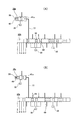
図1は、請求項1〜3に対応する、本発明の実施例1を示している。尚、本実施例の特徴は、運転席に設けたシフトレバーにより手動切換弁32aを後退レンジ(Rレンジ)に切り換えた状態で、高速用クラッチ27の接続を確実に断ったままとすべく、高速クラッチ用油圧室29(図7参照)部分の油圧を確実に断てる構造を低コストで実現する点にある。その他の部分の構造及び作用は、前述の図7に記載した、特願2003−365850号に係る先発明と同様であるから、同等部分に関する図示並びに説明は、省略若しくは簡略にし、以下、本実施例の特徴部分を中心に説明する。   FIG. 1 shows a first embodiment of the present invention corresponding to claims 1 to 3. It should be noted that the feature of this embodiment is that the connection of the high-speed clutch 27 is reliably disconnected while the manual switching valve 32a is switched to the reverse range (R range) by a shift lever provided in the driver's seat. The high-speed clutch hydraulic chamber 29 (see FIG. 7) is configured to reliably cut off the hydraulic pressure at a low cost. Since the structure and operation of the other parts are the same as those of the prior invention related to Japanese Patent Application No. 2003-365850 described in FIG. 7, the illustration and explanation of the equivalent parts are omitted or simplified. The description will focus on the features of the example.

本実施例の場合、上記手動切換弁32aを構成するシリンダ孔68及びスプール69を、前述の図8に示した先発明に係る構造に組み込む手動切換弁32に比べ、軸方向に(図面の左方に)延長している。そして、上記シリンダ孔68のうちで延長した部分(図1の中間部左端寄り部分)に、上記高速クラッチ用油圧室29に通じる上流側排出ポート70と、油溜30に通じる下流側排出ポート71とを設けている。又、上記スプール69のうちで延長した部分の先端部(図1の左端部)に、上記上流側排出ポート70を開閉する為の、高速クラッチ用ランド72を設けている。上記手動切換弁32aの他の部分の構成は、上記先発明に係る構造に組み込む手動切換弁32と同様である。   In the case of the present embodiment, the cylinder hole 68 and the spool 69 constituting the manual switching valve 32a are axially (as compared with the manual switching valve 32 incorporated in the structure according to the previous invention shown in FIG. Towards). Then, an upstream side discharge port 70 communicating with the high speed clutch hydraulic chamber 29 and a downstream side discharge port 71 communicating with the oil reservoir 30 are formed in an extended portion of the cylinder hole 68 (a portion near the left end of the intermediate portion in FIG. 1). And are provided. Further, a high-speed clutch land 72 for opening and closing the upstream discharge port 70 is provided at the tip end portion (left end portion in FIG. 1) of the extended portion of the spool 69. The structure of the other part of the manual switching valve 32a is the same as that of the manual switching valve 32 incorporated in the structure according to the previous invention.

上述の様な構成を有する上記手動切換弁32aは、運転席に設けたシフトレバーをパーキング(P)レンジに位置させた場合には、図1の(A)に示す状態に切り換わる。この状態では、低速クラッチ用、高速クラッチ用両油圧室28、29の何れにも圧油の導入が行なわれなくなって、低速用、高速用両クラッチ26、27(図7)が何れも接続を断たれた状態となる。従って、エンジンや無段変速装置の各部に大きな力が加わる事がなくなる。尚、この状態では、上記両油圧室28、29は、低速クラッチ用、高速クラッチ用両切換弁34、38(図7)を介して、上記油溜30に連通する状態となる。   When the shift lever provided at the driver's seat is positioned in the parking (P) range, the manual switching valve 32a having the above-described configuration is switched to the state shown in FIG. In this state, no pressure oil is introduced into both the hydraulic chambers 28 and 29 for the low speed clutch and the high speed clutch, and both the low speed and high speed clutches 26 and 27 (FIG. 7) are connected. It will be cut off. Therefore, a large force is not applied to each part of the engine and continuously variable transmission. In this state, both the hydraulic chambers 28 and 29 are in communication with the oil reservoir 30 via the low speed clutch and high speed clutch switching valves 34 and 38 (FIG. 7).

次に、運転席に設けたシフトレバーを後退(R)レンジに位置させた場合には、上記手動切換弁32aは、図1の(B)に示す状態に切り換わる。この状態では、低速クラッチ用油圧室28に圧油の導入が行なわれるのに対して、高速ラッチ用油圧室29への圧油の導入が行なわれない状態となり、低速用クラッチ26が接続され、高速用クラッチ27の接続が断たれる。この動作は、前述の図7で説明した先発明の場合と同様である。更に本実施例の場合には、上記手動切換弁32aが図1の(B)に示す状態に切り換えられた状態では、上流側排出ポート70と上記下流側排出ポート71とが連通する。この為、上記高速クラッチ用油圧室29が上記油溜30に、上記手動切換弁32aを介して通じる状態となる。   Next, when the shift lever provided in the driver's seat is positioned in the reverse (R) range, the manual switching valve 32a is switched to the state shown in FIG. In this state, pressure oil is introduced into the low-speed clutch hydraulic chamber 28, but pressure oil is not introduced into the high-speed latch hydraulic chamber 29, and the low-speed clutch 26 is connected. The high speed clutch 27 is disconnected. This operation is the same as that of the prior invention described with reference to FIG. Furthermore, in the case of the present embodiment, the upstream discharge port 70 and the downstream discharge port 71 communicate with each other when the manual switching valve 32a is switched to the state shown in FIG. Therefore, the high speed clutch hydraulic chamber 29 communicates with the oil reservoir 30 via the manual switching valve 32a.

この結果、エンジンの回転速度が低く、低圧側の加圧ポンプ47(図7)から吐出される圧油の量が少ない事で、前述の様に、シフト用切換弁42の切換用パイロット室44(図7)内の油圧上昇が遅れ、このシフト用切換弁42の切り換わりが遅れた場合でも、上記高速クラッチ用油圧室29内の油圧が立ち上がる事はない。従って、上記シフトレバーを後退(R)レンジに位置させた状態では、(上記低速用クラッチ26の接続が極く短時間遅れる事はあっても)上記高速用クラッチ27が接続される事はない。この為、運転者が車両を後退させるモードを選択した場合に、極く短時間、且つ、小さいとは言え、車両を前進させる方向の駆動力が加わる事はない。本実施例の場合、上記Rレンジを選択した状態での、上記高速クラッチ用油圧室29内の油圧排出を、上記手動切換弁32aの切り換えにより行なうので、上記Rレンジ選択時に上記高速用クラッチ27が接続されるのを防止する動作を、確実に(極めて高い信頼性で)行なえる。   As a result, the rotational speed of the engine is low, and the amount of pressure oil discharged from the pressure pump 47 (FIG. 7) on the low pressure side is small. As described above, the switching pilot chamber 44 of the shift switching valve 42 is obtained. Even if the increase in hydraulic pressure in FIG. 7 is delayed and the switching of the shift switching valve 42 is delayed, the hydraulic pressure in the high-speed clutch hydraulic chamber 29 does not rise. Therefore, when the shift lever is in the reverse (R) range, the high speed clutch 27 is not connected (even if the connection of the low speed clutch 26 is delayed for a very short time). . For this reason, when the driver selects the mode for reversing the vehicle, the driving force in the direction of advancing the vehicle is not applied although it is extremely short and small. In the case of the present embodiment, the hydraulic pressure in the high-speed clutch hydraulic chamber 29 is discharged by switching the manual switching valve 32a in the state where the R range is selected. Therefore, the high-speed clutch 27 is selected when the R range is selected. It is possible to reliably (with extremely high reliability) perform an operation for preventing the connection of the.

又、上記シフトレバーをニュートラル(N)レンジに位置させた場合には上記手動切換弁32aは図1の(C)に示す状態に、ドライブ(D)レンジに位置させた場合には同じく(D)に示す状態に、高駆動力前進(L)レンジに位置させた場合には同じく(E)に示す様に、それぞれ切り換わる。このうちのNレンジの場合には、前記Pレンジの場合と同様に、低速クラッチ用、高速ラッチ用両油圧室28、29の何れにも圧油の導入が行なわれなくして、低速用、高速用両クラッチ26、27を何れも接続を断たれた状態とする。又、D、Lレンジの場合には、電磁切換弁46(図7)の開閉に伴って上記低速クラッチ用、高速クラッチ用両油圧室28、29のうちの何れかの油圧室に圧油を導入可能とする。これらの動作は、前述の図7で説明した先発明の場合と同様である。   Further, when the shift lever is positioned in the neutral (N) range, the manual switching valve 32a is in the state shown in FIG. 1C, and when the shift lever is positioned in the drive (D) range, (D ), When they are positioned in the high driving force forward (L) range, they are respectively switched as shown in (E). In the case of the N range, pressure oil is not introduced into both the low pressure clutch and high speed latch hydraulic chambers 28 and 29 as in the case of the P range. Both the clutches 26 and 27 are in a disconnected state. In the case of the D and L ranges, pressure oil is supplied to one of the hydraulic chambers 28 and 29 for the low speed clutch and the high speed clutch as the electromagnetic switching valve 46 (FIG. 7) is opened and closed. It can be introduced. These operations are the same as those of the prior invention described with reference to FIG.

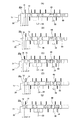
図2は、請求項1、2、4に対応する、本発明の実施例2を示している。本実施例の場合、運転席に設けたシフトレバーにより手動切換弁32bを後退レンジ(Rレンジ)に切り換えた状態で、高速クラッチ用油圧室29(図7)内への油圧の導入とその排出とを制御する為の高速クラッチ用切換弁38aに設けた高速クラッチ用パイロット室41a内に、低圧側の加圧ポンプ47(図7)から吐出された圧油の一部を、直接(前述の図7に示した先発明の様に、シフト用切換弁42等、他の弁を介する事なく)導入する様にしている。   FIG. 2 shows a second embodiment of the present invention corresponding to claims 1, 2, and 4. In the case of this embodiment, introduction and discharge of hydraulic pressure into the hydraulic chamber 29 for high-speed clutch (FIG. 7) in a state where the manual switching valve 32b is switched to the reverse range (R range) by a shift lever provided in the driver's seat. In the high-speed clutch pilot chamber 41a provided in the high-speed clutch switching valve 38a for controlling the pressure, a part of the pressure oil discharged from the pressure pump 47 (FIG. 7) on the low-pressure side is directly (described above). As in the prior invention shown in FIG. 7, the shift switching valve 42 or the like is introduced without any other valve.

上述の様に構成する本実施例の場合、上記手動切換弁32bをRレンジに切り換えると、図2の(A)に示す様に、上記加圧ポンプ47(図7)から吐出された圧油が、上記手動切換弁32bから上記高速クラッチ用パイロット室41a内に、直接送り込まれる。この結果、上記高速クラッチ用切換弁38aが、時間的遅れを殆ど生じる事なく、図2の(A)に示す様な、上記高速クラッチ用パイロット室41aを油溜30に通じさせる状態に切り換わる。そして、高速クラッチ用27(図7)が短時間とは言え接続される事を確実に防止する。   In the case of the present embodiment configured as described above, when the manual switching valve 32b is switched to the R range, the pressure oil discharged from the pressurizing pump 47 (FIG. 7) as shown in FIG. Is directly fed from the manual switching valve 32b into the high speed clutch pilot chamber 41a. As a result, the high speed clutch switching valve 38a is switched to a state where the high speed clutch pilot chamber 41a communicates with the oil reservoir 30, as shown in FIG. . The high-speed clutch 27 (FIG. 7) is reliably prevented from being connected even for a short time.

これに対して、上記手動切換弁32bがRレンジ以外のレンジに切り換えられた場合には、例えば図2の(B)に示す様に、上記加圧ポンプ47の吐出口と上記高速クラッチ用パイロット室41aとが、上記手動切換弁32bを介して連通する事はなくなる。この結果、上記高速用クラッチ27と低速用クラッチ26(図7)との切り換えは、前述の図7に示した先発明の場合と同様にして行なわれる。即ち、本実施例の場合、上記手動切換弁32bと上記高速クラッチ用パイロット室41aとの間に、この手動切換弁32bがRレンジに切り換えられた状態で油圧の導入を行なう為の経路を設けた以外の構成及び作用は、上記先発明の場合と同様である。本実施例の場合、前述した実施例1の場合に比べて手動切換弁32bの軸方向寸法を多少短くできて、この手動切換弁32bの設置の自由度を高められる。上記高速クラッチ用切換弁38aは、前述の図7に示した先発明に組み込むものにポート77を1個加えるのみで足りる為、特にコストが嵩む事はない。   On the other hand, when the manual switching valve 32b is switched to a range other than the R range, for example, as shown in FIG. 2B, the discharge port of the pressurizing pump 47 and the pilot for the high speed clutch. The chamber 41a does not communicate with the manual switching valve 32b. As a result, the switching between the high speed clutch 27 and the low speed clutch 26 (FIG. 7) is performed in the same manner as in the prior invention shown in FIG. That is, in this embodiment, a path is provided between the manual switching valve 32b and the high speed clutch pilot chamber 41a for introducing hydraulic pressure in a state where the manual switching valve 32b is switched to the R range. The configuration and operation other than those described above are the same as in the case of the previous invention. In the present embodiment, the axial dimension of the manual switching valve 32b can be somewhat shortened compared to the case of the first embodiment described above, and the degree of freedom of installation of the manual switching valve 32b can be increased. Since the high-speed clutch switching valve 38a only needs to add one port 77 to the one incorporated in the prior invention shown in FIG. 7, the cost is not particularly increased.

図3は、請求項1、2、5に対応する、本発明の実施例3を示している。本実施例の場合、高速クラッチ用油圧室29と油溜30との間に、電磁弁73を設けている。そして、運転席に設けたシフトレバーを後退レンジに切り換えた状態でこの電磁弁73を解放し、上記高速クラッチ用油圧室29と上記油溜30とを連通させる様にしている。この電磁弁73の開閉を制御する為の制御器74は、上記シフトレバーに付設されたレンジ検出器75からの信号に基づき、上記電磁弁73の開閉を制御する。尚、このレンジ検出器75は、上記シフトレバーの位置を運転席のダッシュボードに表示する為に従来から一般的に設置されているものをそのまま使用できる。即ち、本実施例は、上記電磁弁73と制御器74とレンジ検出器75とを設けた点以外の構成及び作用は、前述の図7に示した先発明の場合と同様である。   FIG. 3 shows a third embodiment of the present invention corresponding to claims 1, 2, and 5. In the present embodiment, an electromagnetic valve 73 is provided between the hydraulic chamber 29 for high speed clutch and the oil reservoir 30. The solenoid valve 73 is released in a state where the shift lever provided in the driver's seat is switched to the reverse range, and the high-speed clutch hydraulic chamber 29 and the oil reservoir 30 are communicated with each other. A controller 74 for controlling the opening / closing of the electromagnetic valve 73 controls the opening / closing of the electromagnetic valve 73 based on a signal from a range detector 75 attached to the shift lever. Note that the range detector 75 can be used as it is, which is generally installed in the past so as to display the position of the shift lever on the dashboard of the driver's seat. That is, this embodiment is the same as the previous invention shown in FIG. 7 except for the point that the electromagnetic valve 73, the controller 74, and the range detector 75 are provided.

本実施例の場合、上記レンジ検出器75が上記シフトレバーが後退レンジにある事を表す信号を上記制御器74に送ると、この制御器74が上記電磁弁73を解放する。この結果、上記高速クラッチ用油圧室29内の油圧が直ちに低下して、高速用クラッチ27が接続される事がなくなる。この様な本実施例の場合、手動切換弁32は、前述の図7に示した先発明を構成するのと同様のものを使用できる。又、上記電磁弁73は小型であり、その設置位置の自由度は大きい。従って、限られた空間に各弁を組み込む為の設計が容易になる。   In this embodiment, when the range detector 75 sends a signal indicating that the shift lever is in the reverse range to the controller 74, the controller 74 releases the electromagnetic valve 73. As a result, the hydraulic pressure in the high-speed clutch hydraulic chamber 29 is immediately reduced and the high-speed clutch 27 is not connected. In this embodiment, the manual switching valve 32 can be the same as that constituting the prior invention shown in FIG. The solenoid valve 73 is small and has a large degree of freedom in its installation position. Therefore, the design for incorporating each valve in a limited space becomes easy.

図4は、請求項1、2、3、6に対応する、本発明の実施例4を示している。本実施例の場合には、手動切換弁32cは、後退(R)レンジ選択時に高速クラッチ用油圧室29(図7)を油溜30に通じさせるのに加えて、非走行状態であるニュートラル(N)レンジとパーキング(P)レンジを選択した場合にも、上記高速クラッチ用油圧室29を上記油溜30に通じさせる様にしている。即ち、本実施例の場合には、図4の(B)に示した様な、後退(R)レンジ選択時だけでなく、この図4の(A)に示したPレンジ及び(C)に示したNレンジの場合も、上記高速クラッチ用油圧室29を上記油溜30に通じさせる様にしている。図4の(D)に示した、前進走行状態であるドライブ(D)レンジ、及び、図4の(E)に示した、高駆動力前進(L)レンジの場合には、上記高速クラッチ用油圧室29と上記油溜30とを連通させる事はない。   FIG. 4 shows a fourth embodiment of the present invention corresponding to claims 1, 2, 3 and 6. In the case of the present embodiment, the manual switching valve 32c allows the high-speed clutch hydraulic chamber 29 (FIG. 7) to communicate with the oil reservoir 30 when the reverse (R) range is selected, and in addition, the neutral ( N) When the range and the parking (P) range are selected, the high-speed clutch hydraulic chamber 29 is communicated with the oil reservoir 30. That is, in the case of this embodiment, not only when the reverse (R) range is selected as shown in FIG. 4B, but also in the P range and (C) shown in FIG. Also in the N range shown, the high speed clutch hydraulic chamber 29 is communicated with the oil reservoir 30. In the case of the drive (D) range in the forward running state shown in (D) of FIG. 4 and the high driving force forward (L) range shown in (E) of FIG. There is no communication between the hydraulic chamber 29 and the oil reservoir 30.

この様に構成する事で、車両を停止させるべく、停止ポジションである上記Pレンジ或はNレンジを選択した場合に、上記高速用クラッチ27が繋がれる事を確実に防止できる。この為、停止時にこの高速用クラッチ27が過って繋がれる事により、各部に無理な力が加わって各部が損傷する事を防止できる。又、図4と前記図1とを比較すれば明らかな通り、上記手動切換弁32cの構成も簡略化できる。即ち、上記高速クラッチ用油圧室29と上記油溜30とを、Rレンジの場合にのみ連通させる構成に比べて、R、P、Nレンジの場合に連通する様に構成する方が、上記手動切換弁32cの構成を簡略化できる。この為、この手動切換弁32cの大型化(軸方向寸法が長くなる事)を防止して、限られた空間への設置の自由度の向上を図れる。
尚、本発明は、図示の様な、ハーフトロイダル型のトロイダル型無段変速機と組み合わせた無段変速装置に限らず、フルトロイダル型のトロイダル型無段変速機と組み合わせた無段変速装置でも実施できる。
With this configuration, it is possible to reliably prevent the high-speed clutch 27 from being engaged when the P range or N range, which is a stop position, is selected to stop the vehicle. For this reason, when the high-speed clutch 27 is excessively connected at the time of stopping, it is possible to prevent each part from being damaged by applying an excessive force to each part. Further, as apparent from a comparison between FIG. 4 and FIG. 1, the configuration of the manual switching valve 32c can be simplified. That is, it is more manual to configure the high-speed clutch hydraulic chamber 29 and the oil reservoir 30 to communicate in the R, P, and N ranges than in the configuration in which only the R range communicates. The configuration of the switching valve 32c can be simplified. For this reason, it is possible to prevent the manual switching valve 32c from becoming large (the axial dimension becomes long) and to improve the degree of freedom of installation in a limited space.
The present invention is not limited to a continuously variable transmission combined with a half-toroidal toroidal continuously variable transmission as shown, but also a continuously variable transmission combined with a full toroidal toroidal continuously variable transmission. Can be implemented.

本発明の実施例1に関して、手動切換弁の切り換え状態を示す断面図。Sectional drawing which shows the switching state of a manual switching valve regarding Example 1 of this invention. 同実施例2に関して、手動切換弁及び高速クラッチ用切換弁の切り換え状態を示す断面図。Sectional drawing which shows the switching state of the manual switching valve and the switching valve for high speed clutch regarding the Example 2. FIG. 同実施例3の油圧回路図。FIG. 6 is a hydraulic circuit diagram of the third embodiment. 同実施例4に関して、手動切換弁の切り換え状態を示す断面図。Sectional drawing which shows the switching state of a manual switching valve regarding the Example 4. FIG. 従来から知られているトロイダル型無段変速機の1例を示す断面図。Sectional drawing which shows an example of the toroidal type continuously variable transmission conventionally known. 従来から知られている無段変速装置の1例を示す略断面図。FIG. 6 is a schematic cross-sectional view showing an example of a conventionally known continuously variable transmission. 先発明に係る、変速比並びに押圧力制御の為の油圧回路図。The hydraulic circuit diagram for gear ratio and pressure control based on a prior invention. 手動切換弁部分を拡大して示す図。The figure which expands and shows a manual switching valve part. 無段変速装置全体としての変速比と、この無段変速装置に組み込んだトロイダル型無段変速機の変速比との関係を示す線図。The diagram which shows the relationship between the gear ratio as the whole continuously variable transmission, and the gear ratio of the toroidal type continuously variable transmission incorporated in this continuously variable transmission.

符号の説明Explanation of symbols

1 入力軸
2 入力側ディスク
3 ボールスプライン
4 出力歯車
5、5a 出力側ディスク
6 パワーローラ
7 トラニオン
8 支持軸
9 駆動軸
10、10a 押圧装置
11 トロイダル型無段変速機
12 遊星歯車式変速機
13 キャリア
14a、14b 遊星歯車素子
15 第一の伝達軸
16a、16b 太陽歯車
17 第二の伝達軸
18 中空回転軸
19 太陽歯車
20 遊星歯車素子
21 リング歯車
22 第二のキャリア
23a、23b 遊星歯車素子
24 出力軸
25 第二のリング歯車
26 低速用クラッチ
27 高速用クラッチ
28 低速クラッチ用油圧室
29 高速クラッチ油圧室
30 油溜
31 加圧ポンプ
32、32a、32b、32c 手動切換弁
33 減圧弁
34 低速クラッチ用切換弁
35 低速クラッチ用スプール
36 低速クラッチ用圧縮コイルばね
37 低速クラッチ用パイロット室
38、38a 高速クラッチ切換弁
39 高速クラッチ用スプール
40 高速クラッチ用圧縮コイルばね
41、41a 高速クラッチ用パイロット室
42 シフト用切換弁
43 切換用スプール
44 切換用パイロット室
45 切換用圧縮コイルばね
46 電磁切換弁
47 加圧ポンプ
48 変速比制御弁
49 スリーブ
50 ステッピングモータ
51 差圧シリンダ
52 ロッド
53 リンク腕
54a、54b 油圧室
55 ロード電磁弁
56 第一の差圧シリンダ
57 第二の差圧シリンダ
58 前後進切換弁
59 電磁弁
60 加圧用圧力調整弁
61 アクチュエータ
62a、62b 油圧室
63 差圧取り出し弁
64 スプール
65a、65b パイロット室
66a、66b 圧力導入路
67a、67b 反力室
68 シリンダ孔
69 スプール
70 上流側排出ポート
71 下流側排出ポート
72 高圧クラッチ用ランド
73 電磁弁
74 制御器
75 レンジ検出器
76 ピストン
77 ポート
DESCRIPTION OF SYMBOLS 1 Input shaft 2 Input side disk 3 Ball spline 4 Output gear 5, 5a Output side disk 6 Power roller 7 Trunnion 8 Support shaft 9 Drive shaft 10, 10a Pressing device 11 Toroidal type continuously variable transmission 12 Planetary gear type transmission 13 Carrier 14a, 14b Planetary gear element 15 First transmission shaft 16a, 16b Sun gear 17 Second transmission shaft 18 Hollow rotation shaft 19 Sun gear 20 Planetary gear element 21 Ring gear 22 Second carrier 23a, 23b Planetary gear element 24 Output Shaft 25 Second ring gear 26 Low speed clutch 27 High speed clutch 28 Low speed clutch hydraulic chamber 29 High speed clutch hydraulic chamber 30 Oil reservoir 31 Pressure pump 32, 32a, 32b, 32c Manual switching valve 33 Pressure reducing valve 34 For low speed clutch Switching valve 35 Spool for low speed clutch 36 Low speed clutch H coil compression coil spring 37 Low speed clutch pilot chamber 38, 38a High speed clutch switching valve 39 High speed clutch spool 40 High speed clutch compression coil spring 41, 41a High speed clutch pilot chamber 42 Shift switching valve 43 Switching spool 44 For switching Pilot chamber 45 Compression coil spring for switching 46 Electromagnetic switching valve 47 Pressure pump 48 Gear ratio control valve 49 Sleeve 50 Stepping motor 51 Differential pressure cylinder 52 Rod 53 Link arms 54a and 54b Hydraulic chamber 55 Load electromagnetic valve 56 First differential pressure Cylinder 57 Second differential pressure cylinder 58 Forward / reverse switching valve 59 Solenoid valve 60 Pressure adjusting valve 61 for pressurization 61 Actuator 62a, 62b Hydraulic chamber 63 Differential pressure take-off valve 64 Spool 65a, 65b Pilot chamber 66a, 66b Pressure introduction path 67a, 7b reaction force chamber 68 the cylinder bore 69 the spool 70 upstream exhaust port 71 downstream discharge port 72 for high-pressure clutch lands 73 solenoid valve 74 controller 75 range detector 76 the piston 77 ports

Claims (7)

入力軸と出力軸との間に設けられたトロイダル型無段変速機と遊星歯車式変速機とを、クラッチ装置を介して組み合わせて成り、このクラッチ装置は、減速比を大きくする低速モードを実現する際に接続され、減速比を小さくする高速モードを実現する際に接続を断たれる低速用クラッチと、この高速モードを実現する際に接続されて上記低速モードを実現する際に接続を断たれる高速用クラッチと、これら各クラッチの断接状態を切り換える制御回路とから成り、この制御回路は、これら各クラッチの断接を制御する事により、変速状態を上記低速モードと上記高速モードとのうちの何れかのモードにするものであり、このうちの低速モードが選択された状態では、上記入力軸を一定方向に回転させた状態のまま、上記出力軸の回転方向を、この出力軸の停止状態を挟んで、車両を前進させる方向と後退させる方向とに変換自在であり、この出力軸の回転方向は、手動切換弁の切り換えに基づいて選択される無段変速装置に於いて、この手動切換弁を、上記出力軸の回転方向を車両を後退させる方向に切り換えた状態では、上記高速用クラッチが接続される可能性をなくした事を特徴とする無段変速装置。   Combining a toroidal-type continuously variable transmission and planetary gear type transmission between the input shaft and output shaft via a clutch device, this clutch device realizes a low-speed mode that increases the reduction ratio. And a low-speed clutch that is disconnected when realizing the high-speed mode that reduces the reduction ratio, and a connection that is disconnected when realizing the high-speed mode and disconnecting when realizing the low-speed mode. And a control circuit for switching the connection / disconnection state of the clutches. The control circuit controls the connection / disconnection state of the clutches, thereby changing the shift state between the low speed mode and the high speed mode. When the low speed mode is selected, the rotation direction of the output shaft is changed while the input shaft is rotated in a certain direction. The output shaft can be converted into a forward direction and a reverse direction across the stop state of the output shaft. The rotational direction of the output shaft is determined by the continuously variable transmission selected based on switching of the manual switching valve. A continuously variable transmission, wherein the high-speed clutch is not connected when the manual switching valve is switched to a direction in which the rotation direction of the output shaft is moved backward. 高速用クラッチが、油溜から吸引されて加圧ポンプから吐出された圧油を高速クラッチ用油圧室に送り込む事に伴って繋がれるものであり、手動切換弁が出力軸の回転方向を車両を後退させる方向に切り換えられた状態で、上記高速クラッチ用油圧室を上記油溜に向けて解放する事により、この高速クラッチ用油圧室内の油圧が立ち上がる事を禁止する、請求項1に記載した無段変速装置。   The high-speed clutch is connected as the pressure oil sucked from the oil reservoir and discharged from the pressure pump is fed into the hydraulic chamber for the high-speed clutch. 2. The non-reactor according to claim 1, wherein the hydraulic pressure chamber in the high-speed clutch hydraulic chamber is prohibited from rising by releasing the high-speed clutch hydraulic chamber toward the oil reservoir in a state of being switched to the reverse direction. Step transmission. 手動切換弁に、この手動切換弁が出力軸の回転方向を車両を後退させる方向に切り換えられた状態で、高速クラッチ用油圧室を油溜に通じさせる通路を設けた、請求項2に記載した無段変速装置。   3. The passage according to claim 2, wherein the manual switching valve is provided with a passage through which the hydraulic chamber for the high-speed clutch communicates with the oil reservoir in a state where the manual switching valve is switched to the direction in which the rotation direction of the output shaft is moved backward. Continuously variable transmission. パイロット室内への油圧の導入に伴って高速クラッチ用油圧室内の油圧を排出する状態に、このパイロット室内からの油圧の排出に伴ってこの高速クラッチ用油圧室内に油圧を導入可能とする状態に、それぞれ切り換えられる高速クラッチ用切換弁を設け、手動切換弁が出力軸の回転方向を車両を後退させる方向に切り換えられた状態で、この手動切換弁を通過した圧油を上記パイロット室内に直接送り込む、請求項2に記載した無段変速装置。   In a state where the hydraulic pressure in the hydraulic chamber for the high speed clutch is discharged along with the introduction of the hydraulic pressure into the pilot chamber, and in a state where the hydraulic pressure can be introduced into the hydraulic chamber for the high speed clutch as the hydraulic pressure is discharged from the pilot chamber, A switching valve for a high-speed clutch that can be switched is provided, and with the manual switching valve being switched to a direction in which the rotation direction of the output shaft is moved backward, the pressure oil that has passed through the manual switching valve is directly fed into the pilot chamber. The continuously variable transmission according to claim 2. 解放に伴って高速クラッチ用油圧室と油溜とを連通させる電磁弁を設け、手動切換弁が出力軸の回転方向を車両を後退させる方向に切り換えられた状態で上記電磁弁を解放する、請求項2に記載した無段変速装置。   A solenoid valve that communicates the hydraulic chamber for the high-speed clutch and the oil reservoir in connection with the release is provided, and the solenoid valve is released in a state in which the manual switching valve is switched to the direction in which the rotation direction of the output shaft is moved backward. The continuously variable transmission according to Item 2. 手動切換弁は、出力軸の回転方向を2通りに選択されるポジションに加え、この出力軸を回転させない停止ポジションを選択自在としており、上記手動切換弁がこの停止ポジションに位置する状態で、高速クラッチ用油圧室を油溜に向けて解放する事により、この高速クラッチ用油圧室内の油圧が立ち上がる事を禁止する、請求項2〜5の何れかに記載した無段変速装置。   In addition to the position where the rotation direction of the output shaft is selected in two ways, the manual switching valve can be freely selected as a stop position that does not rotate the output shaft. The continuously variable transmission according to any one of claims 2 to 5, wherein a hydraulic pressure in the hydraulic chamber for high speed clutch is prohibited from rising by releasing the hydraulic chamber for clutch toward an oil reservoir. 低速モードと高速モードとの切換時に低速用クラッチと高速用クラッチとの両方のクラッチを同時に接続する瞬間を設けた、請求項1〜6の何れかに記載した無段変速装置。   The continuously variable transmission according to any one of claims 1 to 6, wherein a moment for simultaneously connecting both the low speed clutch and the high speed clutch is provided when switching between the low speed mode and the high speed mode.
JP2004002762A 2004-01-08 2004-01-08 Continuously variable transmission Pending JP2005195106A (en)

Priority Applications (1)

Application Number Priority Date Filing Date Title
JP2004002762A JP2005195106A (en) 2004-01-08 2004-01-08 Continuously variable transmission

Applications Claiming Priority (1)

Application Number Priority Date Filing Date Title
JP2004002762A JP2005195106A (en) 2004-01-08 2004-01-08 Continuously variable transmission

Publications (2)

Publication Number Publication Date
JP2005195106A true JP2005195106A (en) 2005-07-21
JP2005195106A5 JP2005195106A5 (en) 2006-11-30

Family

ID=34817856

Family Applications (1)

Application Number Title Priority Date Filing Date
JP2004002762A Pending JP2005195106A (en) 2004-01-08 2004-01-08 Continuously variable transmission

Country Status (1)

Country Link
JP (1) JP2005195106A (en)

Citations (6)

* Cited by examiner, † Cited by third party
Publication number Priority date Publication date Assignee Title
JPH09210191A (en) * 1996-01-31 1997-08-12 Nissan Motor Co Ltd Shift controller for continuously variable transmission with gear ratio of infinity
JPH10252883A (en) * 1997-03-10 1998-09-22 Nissan Motor Co Ltd Oil pressure control device for continuously variable transmission having infinity change gear ratio
JPH10252875A (en) * 1997-03-10 1998-09-22 Nissan Motor Co Ltd Oil pressure control device for continuously variable transmission having infinity change gear ratio
JP2001041309A (en) * 1999-07-28 2001-02-13 Mazda Motor Corp Toroidal continuously variable transmission
JP2001280477A (en) * 2000-03-30 2001-10-10 Nissan Motor Co Ltd Controller for gear ratio infinity step less transmission
JP2002276786A (en) * 2001-03-19 2002-09-25 Mazda Motor Corp Toroidal cvt control device

Patent Citations (6)

* Cited by examiner, † Cited by third party
Publication number Priority date Publication date Assignee Title
JPH09210191A (en) * 1996-01-31 1997-08-12 Nissan Motor Co Ltd Shift controller for continuously variable transmission with gear ratio of infinity
JPH10252883A (en) * 1997-03-10 1998-09-22 Nissan Motor Co Ltd Oil pressure control device for continuously variable transmission having infinity change gear ratio
JPH10252875A (en) * 1997-03-10 1998-09-22 Nissan Motor Co Ltd Oil pressure control device for continuously variable transmission having infinity change gear ratio
JP2001041309A (en) * 1999-07-28 2001-02-13 Mazda Motor Corp Toroidal continuously variable transmission
JP2001280477A (en) * 2000-03-30 2001-10-10 Nissan Motor Co Ltd Controller for gear ratio infinity step less transmission
JP2002276786A (en) * 2001-03-19 2002-09-25 Mazda Motor Corp Toroidal cvt control device

Similar Documents

Publication Publication Date Title
JP4168785B2 (en) Method and apparatus for controlling gear ratio of toroidal continuously variable transmission unit for continuously variable transmission
JP4378991B2 (en) Continuously variable transmission
JPH06213318A (en) Running shift structure of working vehicle
US7326147B2 (en) Continuously variable transmission apparatus
JP2007154979A (en) Toroidal type continuously variable transmission, and continuously variable transmission device
JP4599905B2 (en) Continuously variable transmission
JP4556427B2 (en) Continuously variable transmission
JP4010145B2 (en) Toroidal continuously variable transmission and continuously variable transmission
JP4529442B2 (en) Toroidal continuously variable transmission
US7273440B2 (en) Continuously variable transmission apparatus
JP2005195106A (en) Continuously variable transmission
JP4479181B2 (en) Toroidal continuously variable transmission
JP4670569B2 (en) Continuously variable transmission
JP4457746B2 (en) Toroidal continuously variable transmission
JP4273750B2 (en) Toroidal continuously variable transmission
JP4442223B2 (en) Differential pressure relief valve for toroidal type continuously variable transmission
JP2004211744A (en) Continuously variable transmission device
JP4016745B2 (en) Continuously variable transmission
JP2004197934A (en) Continuously variable transmission
US11796041B2 (en) Planetary gear assembly, power-split stepless transmission, and transmission structure
JP4940589B2 (en) Continuously variable transmission
JP2008014357A (en) Continuously variable transmission
JP5181470B2 (en) Continuously variable transmission
JP2004116577A (en) Continuously variable transmission
JP4192495B2 (en) Continuously variable transmission

Legal Events

Date Code Title Description
A521 Written amendment

Free format text: JAPANESE INTERMEDIATE CODE: A523

Effective date: 20061016

A621 Written request for application examination

Free format text: JAPANESE INTERMEDIATE CODE: A621

Effective date: 20061016

RD04 Notification of resignation of power of attorney

Free format text: JAPANESE INTERMEDIATE CODE: A7424

Effective date: 20061016

A977 Report on retrieval

Free format text: JAPANESE INTERMEDIATE CODE: A971007

Effective date: 20090917

A131 Notification of reasons for refusal

Free format text: JAPANESE INTERMEDIATE CODE: A131

Effective date: 20090929

A02 Decision of refusal

Free format text: JAPANESE INTERMEDIATE CODE: A02

Effective date: 20100406