JP2005184788A - Signal processing device - Google Patents
Signal processing device Download PDFInfo
- Publication number
- JP2005184788A JP2005184788A JP2004335402A JP2004335402A JP2005184788A JP 2005184788 A JP2005184788 A JP 2005184788A JP 2004335402 A JP2004335402 A JP 2004335402A JP 2004335402 A JP2004335402 A JP 2004335402A JP 2005184788 A JP2005184788 A JP 2005184788A
- Authority
- JP
- Japan
- Prior art keywords
- display
- data
- video data
- signal processing
- decoder
- Prior art date
- Legal status (The legal status is an assumption and is not a legal conclusion. Google has not performed a legal analysis and makes no representation as to the accuracy of the status listed.)
- Pending
Links
Images


Classifications
-
- H—ELECTRICITY
- H04—ELECTRIC COMMUNICATION TECHNIQUE
- H04N—PICTORIAL COMMUNICATION, e.g. TELEVISION
- H04N5/00—Details of television systems
- H04N5/76—Television signal recording
- H04N5/765—Interface circuits between an apparatus for recording and another apparatus
- H04N5/775—Interface circuits between an apparatus for recording and another apparatus between a recording apparatus and a television receiver
-
- Y—GENERAL TAGGING OF NEW TECHNOLOGICAL DEVELOPMENTS; GENERAL TAGGING OF CROSS-SECTIONAL TECHNOLOGIES SPANNING OVER SEVERAL SECTIONS OF THE IPC; TECHNICAL SUBJECTS COVERED BY FORMER USPC CROSS-REFERENCE ART COLLECTIONS [XRACs] AND DIGESTS
- Y10—TECHNICAL SUBJECTS COVERED BY FORMER USPC
- Y10S—TECHNICAL SUBJECTS COVERED BY FORMER USPC CROSS-REFERENCE ART COLLECTIONS [XRACs] AND DIGESTS
- Y10S370/00—Multiplex communications
- Y10S370/916—Multiplexer/demultiplexer
Abstract
Description
本発明は信号処理装置に関する。 The present invention relates to a signal processing apparatus.
従来、テレビ放送受信機において、特許文献1に記載の様に、二つのチューナを持ち、二つの番組を同時に表示可能な装置が知られている。また特許文献2には複数の処理モジュールを備えたテレビジョン受信機が開示されている。
本願発明は好適なデコード及びもしくは好適なデマルチプレクスを実現することを課題とする。 It is an object of the present invention to realize suitable decoding and / or suitable demultiplexing.
具体的な課題の一例としては、複数の表示領域を用いて表示を行う構成を簡易に実現できる構成を実現すること、及びもしくは複数の表示領域を用いた表示を高品位に実現できる構成を実現すること、を挙げることができる。 As an example of a specific problem, a configuration capable of easily realizing a configuration for displaying using a plurality of display areas, or a configuration capable of realizing a high-quality display using a plurality of display areas is realized. To do.
本願に係わる発明の一つは、
信号処理装置であって、
データをデコードして映像データを発生させる第1のデコーダと、
データをデコードして映像データを発生させる第2のデコーダとを有しており、
前記データをデコードして前記映像データを発生させるための所定の演算処理に関して、前記第2のデコーダが単位時間あたりに実行できる前記所定の演算処理の回数は、前記第1のデコーダが単位時間あたりに実行できる前記所定の演算処理の回数よりも少ない。
One of the inventions related to this application is:
A signal processing device comprising:
A first decoder for decoding the data to generate video data;
A second decoder for decoding the data to generate video data;
Regarding the predetermined arithmetic processing for decoding the data and generating the video data, the number of the predetermined arithmetic processing that the second decoder can execute per unit time is the number of times the first decoder performs per unit time. Less than the predetermined number of operations that can be executed.
例えば第1のデコーダが出力する映像データの解像度よりも、第2のデコーダが出力する映像データの解像度を低くすることによって、デコードに係わる例えば逆DCT処理などの所定の演算回数を抑制することができる。1つの画面を構成するための演算回数を減らすことができるので、単位時間(1秒間)で見た場合の演算回数は第2のデコーダでは第1のデコーダよりも少なくてよい。 For example, by reducing the resolution of the video data output by the second decoder from the resolution of the video data output by the first decoder, the predetermined number of computations such as inverse DCT processing related to decoding can be suppressed. it can. Since the number of operations for configuring one screen can be reduced, the number of operations when viewed in unit time (1 second) may be smaller in the second decoder than in the first decoder.
またこの発明において、更に、順次に入力されるパケットデータから、該パケットデータの識別子に応じて複数の種類(type)のデータをそれぞれ識別して取り出す第1のデマルチプレクサと、順次に入力されるパケットデータから、該パケットデータの識別子に応じて前記複数の種類よりも少ない種類のデータを識別して取り出す第2のでマルチプレクサと、を有しており、前記第1のデコーダは前記第1のデマルチプレクサで取り出されたデータをデコードし、前記第2のデコーダは前記第2のデマルチプレクさで取り出されたデータをデコードする構成を好適に採用できる。 Further, in the present invention, a first demultiplexer that sequentially identifies and extracts a plurality of types of data according to an identifier of the packet data from sequentially input packet data, and sequentially input. A second multiplexer for identifying and extracting from the packet data less than the plurality of types of data according to the identifier of the packet data, and the first decoder includes the first decoder. A configuration in which data extracted by the multiplexer is decoded and the second decoder decodes the data extracted by the second demultiplexing can be suitably employed.
第2のデマルチプレクサで取り出されなかった種類のデータは破棄すればよい。 The type of data that has not been extracted by the second demultiplexer may be discarded.
また上記発明において、前記第1のデコーダ及び/もしくは第2のデコーダに入力するデータを受信するための受信装置を更に有する構成を好適に採用できる。特に、この受信装置が、前記第1のデコーダでデコードするデータを受信するための受信回路と、前記第2のデコーダでデコードするデータを受信するための受信回路と、を有する構成を好適に採用できる。 In the above invention, a configuration further including a receiving device for receiving data input to the first decoder and / or the second decoder can be suitably employed. In particular, the receiving apparatus preferably employs a configuration having a receiving circuit for receiving data decoded by the first decoder and a receiving circuit for receiving data decoded by the second decoder. it can.
受信装置で受信した信号を一時記憶装置に記憶してからデコーダに入力してもよい。以下で説明する実施形態のように、デマルチプレクサを用いる場合には、受信装置で受信した信号を一時記憶装置に記憶してから,デマルチプレクサを介してデコーダに入力してもよい。この記憶装置としては、デコーダ及びもしくはデマルチプレクスなどの信号処理のために必要な期間、必要なデータを記憶できればよいので、例えば1乃至複数フレーム分の記憶容量があれば足りる。またある番組を記憶装置に記憶しておき、この記憶装置からのデータを第1のデコーダ(及び/もしくは第1のデマルチプレクサ)もしくは第2のデコーダ(及び/もしくは第2のデマルチプレクサ)への入力として用いることもできる。この場合は記憶装置の容量は番組を記憶できる程度に必要であり、好適には1ギガバイト以上の容量があることが望ましい。またDVDなどの記録メディアから読み出したデータを第1のデコーダ(及び/もしくは第1のデマルチプレクサ)もしくは第2のデコーダ(及び/もしくは第2のデマルチプレクサ)への入力として用いることもできる。 The signal received by the receiving device may be stored in the temporary storage device and then input to the decoder. When a demultiplexer is used as in the embodiment described below, the signal received by the receiving device may be stored in the temporary storage device and then input to the decoder via the demultiplexer. As this storage device, it is sufficient to store necessary data for a period required for signal processing such as a decoder and / or demultiplexing, so that it is sufficient to have a storage capacity for one to a plurality of frames, for example. A program is stored in a storage device, and data from the storage device is sent to the first decoder (and / or the first demultiplexer) or the second decoder (and / or the second demultiplexer). It can also be used as input. In this case, the capacity of the storage device is necessary so that the program can be stored, and it is desirable that the capacity is preferably 1 gigabyte or more. Data read from a recording medium such as a DVD can also be used as an input to the first decoder (and / or the first demultiplexer) or the second decoder (and / or the second demultiplexer).
また本願は以下の信号処理装置の発明も含んでいる。 The present application also includes the invention of the following signal processing apparatus.
信号処理装置であって、
順次に入力されるパケットデータから、該パケットデータの識別子に応じて複数の種類(type)のデータをそれぞれ識別して取り出す第1のデマルチプレクサと、
順次に入力されるパケットデータから、該パケットデータの識別子に応じて前記複数の種類よりも少ない種類のデータを識別して取り出す第2のデマルチプレクサとを有する。
A signal processing device comprising:
A first demultiplexer that identifies and extracts a plurality of types of data from packet data that is sequentially input according to an identifier of the packet data;
A second demultiplexer that identifies and extracts data of less than the plurality of types according to an identifier of the packet data from sequentially input packet data.
また本願は以下の信号処理装置の発明も含んでいる。 The present application also includes the invention of the following signal processing apparatus.
信号処理装置であって、
信号処理回路と、
データをデコードして映像データを発生させる処理を前記信号処理回路で行うためのプログラムを記憶する記憶装置と、
を有しており、
前記プログラムは、
表示デバイスの表示可能領域のうちの第1の表示領域において表示を行うための映像データを発生させる処理と、前記第1の表示領域とは同一ではない第2の表示領域において表示を行うための映像データを発生させる処理と、を実行するように構成されており、かつ、
前記データをデコードして前記映像データを発生させるための所定の演算処理に関して、前記第2の表示領域において表示を行うための映像データを発生させる処理の一部として実行する前記所定の演算処理の単位時間あたりの回数は、前記第1の表示領域において表示を行うための映像データを発生させる処理の一部として実行する前記所定の演算処理の単位時間あたりの回数よりも小さくなるように構成されている。
A signal processing device comprising:
A signal processing circuit;
A storage device for storing a program for performing processing for decoding video data and generating video data in the signal processing circuit;
Have
The program is
Processing for generating video data for display in the first display area of the displayable areas of the display device, and display in a second display area that is not the same as the first display area And a process for generating video data, and
Regarding the predetermined arithmetic processing for decoding the data and generating the video data, the predetermined arithmetic processing executed as part of the processing for generating the video data for display in the second display area. The number of times per unit time is configured to be smaller than the number of times of the predetermined arithmetic processing executed as a part of processing for generating video data for display in the first display area. ing.
この発明において、前記第1の表示領域の面積は、前記第2の表示領域の面積よりも大きい構成を好適に採用できる。 In the present invention, a configuration in which the area of the first display region is larger than the area of the second display region can be suitably employed.
また本願は以下の信号処理装置の発明を含んでいる。 In addition, the present application includes the invention of the following signal processing apparatus.
信号処理装置であって、
信号処理回路と、
入力されるデータを復号して映像データを発生させる処理を前記信号処理回路で行うためのプログラムを記憶する記憶装置と、
を有しており、
前記プログラムは、
表示デバイスの表示可能領域のうちの所定の表示領域において表示を行うための映像データを発生させる処理を実行する第1の状態と、
前記表示可能領域のうちの第1の表示領域において表示を行うための映像データを発生させる処理と、前記第1の表示領域とは同一ではない第2の表示領域において表示を行うための映像データを発生させる処理と、を実行する第2の状態と、を切り替え可能に構成されている。
A signal processing device comprising:
A signal processing circuit;
A storage device for storing a program for performing processing in the signal processing circuit to decode input data and generate video data;
Have
The program is
A first state of executing processing for generating video data for display in a predetermined display area of the displayable area of the display device;
Processing for generating video data for display in a first display area of the displayable areas, and video data for display in a second display area that is not the same as the first display area And a second state in which the process is executed can be switched.
ここで所定の表示領域は表示可能領域と同じであってもよい。また第1の表示領域もしくは第2の表示領域のいずれかは表示可能領域と同じであってもよい。 Here, the predetermined display area may be the same as the displayable area. Further, either the first display area or the second display area may be the same as the displayable area.
またこの発明において、入力される前記データをデコードして前記映像データを発生させるための所定の演算処理に関して、前記第1の表示領域において表示を行うための映像データを発生させる処理の一部として実行する前記所定の演算処理の単位時間あたりの回数、及び、前記第2の表示領域において表示を行うための映像データを発生させる処理の一部として実行する前記所定の演算処理の単位時間あたりの回数は、いずれも、前記所定の表示領域において表示を行うための映像データを発生させる処理の一部として実行する前記所定の演算処理ステップの単位時間あたりの数よりも小さい構成を好適に採用できる。特に、前記プログラムが、表示デバイスの表示可能領域のうちの所定の表示領域において表示を行うための映像データを発生させる処理を実行する第1のプログラムと、前記表示可能領域のうちの第1の表示領域において表示を行うための映像データを発生させる処理と、前記第1の表示領域とは同一ではない第2の表示領域において表示を行うための映像データを発生させる処理と、を実行する第2のプログラムと、を有する構成を好適に採用できる。第1のプログラムを実行する状態と、第2のプログラムを実行する状態とを切り替えることで第1の状態と第2の状態とを切り替えることができる。 Further, in the present invention, as a part of a process for generating video data for display in the first display area, a predetermined calculation process for decoding the input data and generating the video data. The number of the predetermined arithmetic processing to be executed per unit time and the predetermined arithmetic processing per unit time to be executed as a part of the processing for generating video data for display in the second display area In any case, the number of times can be suitably adopted to be smaller than the number per unit time of the predetermined arithmetic processing step executed as a part of the process of generating video data for display in the predetermined display area. . In particular, the program executes a process of generating video data for display in a predetermined display area of the display device displayable area, and a first of the displayable areas. A process for generating video data for display in a display area and a process for generating video data for display in a second display area that is not the same as the first display area; The configuration having two programs can be suitably employed. The first state and the second state can be switched by switching between a state in which the first program is executed and a state in which the second program is executed.
また本願は以下の信号処理装置の発明を含んでいる。 In addition, the present application includes the invention of the following signal processing apparatus.
信号処理装置であって、
データをデコードして映像データを発生させる信号処理回路と、
該信号処理回路の動作状態を変更するための書き換えデータを記憶する記憶装置と、
を有しており、
前記信号処理回路は、
表示デバイスの表示可能領域のうちの所定の表示領域において表示を行うための映像データを発生させる処理を実行する第1の状態と、
前記表示可能領域のうちの第1の表示領域において表示を行うための映像データを発生させる処理と、前記第1の表示領域とは同一ではない第2の表示領域において表示を行うための映像データを発生させる処理と、を実行する第2の状態と、を前記書き換えデータに基づいて切り替え可能である。
A signal processing device comprising:
A signal processing circuit that decodes data to generate video data;
A storage device for storing rewrite data for changing an operation state of the signal processing circuit;
Have
The signal processing circuit includes:
A first state of executing processing for generating video data for display in a predetermined display area of the displayable area of the display device;
Processing for generating video data for display in a first display area of the displayable areas, and video data for display in a second display area that is not the same as the first display area Can be switched based on the rewrite data.
また本願は以下のプログラムの発明を含んでいる。 The present application also includes the following program inventions.
表示を行うための映像データを発生させるプログラムであって、
表示デバイスの表示可能領域のうちの第1の表示領域において表示を行うための映像データを発生させる処理と、前記第1の表示領域とは同一ではない第2の表示領域において表示を行うための映像データを発生させる処理と、を実行するように構成されており、かつ、
入力される前記データをデコードして前記映像データを発生させるための所定の演算処理に関して、前記第2の表示領域において表示を行うための映像データを発生させる処理の一部として実行する前記所定の演算処理の単位時間あたりの回数は、前記第1の表示領域において表示を行うための映像データを発生させる処理の一部として実行する前記所定の演算処理の単位時間あたりの回数よりも小さくなるように構成されている。
A program for generating video data for display,
Processing for generating video data for display in the first display area of the displayable areas of the display device, and display in a second display area that is not the same as the first display area And a process for generating video data, and
Regarding the predetermined calculation processing for decoding the input data and generating the video data, the predetermined processing executed as part of the processing for generating video data for display in the second display area The number of operations per unit time is smaller than the number of operations per unit time of the predetermined operation executed as part of the process for generating video data for display in the first display area. It is configured.
また本願は上に述べた信号処理装置と、前記映像データに基づく表示を行う表示デバイスとを有する表示装置の発明を含んでいる。表示デバイスとしては電界放出素子を表示素子として用いた電界放出ディスプレイや、プラズマセルを表示素子として用いるプラズマディスプレイや、液晶セルを表示素子として用いる液晶ディスプレイや、エレクトロルミネッセンス素子を表示素子として用いるエレクトロルミネッセンスディスプレイや、CRTなどを用いることができる。 The present application also includes an invention of a display device having the signal processing device described above and a display device that performs display based on the video data. As a display device, a field emission display using a field emission element as a display element, a plasma display using a plasma cell as a display element, a liquid crystal display using a liquid crystal cell as a display element, and an electroluminescence using an electroluminescence element as a display element A display, a CRT, or the like can be used.
また具体的には、
伝送信号を受信し選局、復調するための複数の放送受信手段と、
前記放送受信手段によって選局、復調された放送データをそれぞれ所定の領域に記憶する記憶手段と、
前記記憶手段に記憶された映像、音声、データ放送、及び制御用データ全てを分別する完全分別手段と、前記記憶手段に記憶された映像、音声、データ放送、及び制御用データのうちの一部を分別する簡易分別手段とを含み、前記分別したデータを前記記憶手段に再び書き込む分別部と、
高解像度映像データを高解像度で処理できる高解像度映像復号手段と高解像度映像データを低い解像度で復号する低解像度映像復号手段とを含み、前記分別手段により分別された映像データを復号する映像復号部とを備える信号処理装置の構成を開示している。
Specifically,
A plurality of broadcast receiving means for receiving, selecting and demodulating a transmission signal;
Storage means for storing broadcast data demodulated and demodulated by the broadcast receiving means in respective predetermined areas;
Complete classification means for separating all video, audio, data broadcast, and control data stored in the storage means, and part of the video, audio, data broadcast, and control data stored in the storage means A simple sorting means for sorting, and a sorting section for rewriting the sorted data in the storage means,
Video decoding unit including high resolution video decoding means capable of processing high resolution video data at high resolution and low resolution video decoding means for decoding high resolution video data at low resolution, and decoding the video data sorted by the classification means Is disclosed.
また前記分別部は、1つの分別手段のみで前記記憶手段に記憶されている複数の放送番組のデータを順番に分別することを特徴とする構成を開示している。 Moreover, the said classification | fractionation part has disclosed the structure characterized by classifying the data of the several broadcast program memorize | stored in the said memory | storage means in order only with one classification | category means.
また前記低解像度映像復号手段は、参照元となる最初の画像のみは高解像度で復号し、その他の画像は低解像度で復号することを特徴とする構成を開示している。 Further, the low resolution video decoding means discloses a configuration characterized in that only the first image as a reference source is decoded at a high resolution, and other images are decoded at a low resolution.
また、
伝送信号を受信し選局、復調するための複数の放送受信手段と、
前記放送受信手段によって選局、復調された放送データをそれぞれ所定の領域に記憶する記憶手段と、
前記記憶手段に記憶された放送データを映像、音声、データ放送、その他制御用データを分別し再度記憶手段に記憶する分別手段と、
前記分別手段により分別された映像データを復号するための映像復号手段と、
表示画面の構成に応じて前記分別手段の分別するデータの種類を変更すると共に、前記映像復号手段の処理できる解像度を変更する制御手段とを備える信号処理装置の構成を開示している。
Also,
A plurality of broadcast receiving means for receiving, selecting and demodulating a transmission signal;
Storage means for storing broadcast data demodulated and demodulated by the broadcast receiving means in respective predetermined areas;
Classification means for separating video, audio, data broadcast, and other control data from the broadcast data stored in the storage means and storing them again in the storage means;
Video decoding means for decoding the video data sorted by the sorting means;
A configuration of a signal processing device is disclosed that includes a control unit that changes the type of data to be sorted by the sorting unit according to the configuration of the display screen and changes the resolution that can be processed by the video decoding unit.
ここで前記映像復号手段は、参照元となる最初の画像のみは必ず高解像度で復号することを特徴とする構成も開示している。 Here, the video decoding means also discloses a configuration in which only the first image as a reference source is always decoded with high resolution.
本発明によると好適なデコード及びもしくは好適なデマルチプレクスを行うことが可能となる。 According to the present invention, suitable decoding and / or suitable demultiplexing can be performed.
図1はデジタル放送受信におけるシステム構成例である。このシステムは、デジタル放送を受信し複数の番組の受信結果を出力するIRD(Integrated Receiver/Decoder)1、IRD1の映像、音声を視聴するためのモニタ2、IRD1とモニタ2間の映像及び音声信号を伝送するためのケーブル3、IRD1に命令を送るためのリモートコントローラ(以後リモコン)4、衛星や地上波等のデジタルテレビ放送信号を受信するためのアンテナ5を有している。
FIG. 1 is a system configuration example in digital broadcast reception. This system includes an IRD (Integrated Receiver / Decoder) 1 that receives a digital broadcast and outputs a reception result of a plurality of programs, an IRD1 video, a monitor 2 for viewing audio, and a video and audio signal between the IRD1 and the monitor 2 , A remote controller (hereinafter referred to as a remote controller) 4 for sending commands to the
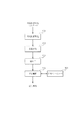
図2にデジタル放送を受信するためのIRD1の構成例を示す。
FIG. 2 shows a configuration example of the
IRD1は、放送受信部a201a、放送受信部201b、DTVモジュール202、簡易DTVモジュール301、記憶部203、CPU204、CAM205、表示データ生成部206、D/A変換部207、操作部208、TS蓄積部209、番組情報記憶部201、およびこれらの間での信号の伝送を行うためのバスとを有する。
The
放送受信部201aは、アンテナ5から入力されるデジタル放送信号を選局するチューナー2001aを有しており、TSデータを出力する。放送受信部201bは、アンテナ5から入力されるデジタル放送信号を選局するチューナー2001bを有しており、TSデータを出力する。DTVモジュール202には、放送受信部201aから出力されるTSデータが、記憶手段203を経由して入力される。DTVモジュール202は、入力されたTSデータをデマルチプレクスし、取り出した制御データを出力する。デマルチプレクスによって取り出された映像データ及びオーディオデータはデコードしてから出力する。
The
DTVモジュール202の構成を図2右下に示している。DTVモジュール202はTSデータを構成するパケットデータをパケット識別子(PID)に基づいてデマルチプレクスすることで識別子に応じたデータをそれぞれ取り出すデマルチプレクサ211と、デマルチプレクサ211で取り出された映像データをデコードしてデコードされた映像データを出力するMPEG2ビデオデコーダ212と、デマルチプレクサ211で取り出された音声データをデコードしてデコードされた音声データを出力するMPEG2オーディオデコーダ213と、を有している。なお、デマルチプレクサ211は入力されるパケットデータの識別子に応じて、映像データ、音声データ、データ放送、番組情報等のデータを分別し、それぞれを出力する。
The configuration of the
簡易DTVモジュール301には、放送受信部201bから出力されるTSデータが、記憶手段203を経由して入力される。簡易DTVモジュール301は入力されたTSデータをデマルチプレクスするとともに、デマルチプレクスによって取り出された映像データ及びオーディオデータをデコードする。DTVモジュール301は、デコードした音声データ、及びダウンサンプリングしてデコードした映像データ、及びその他のデータのうちの前記映像データ及び音声データの再生に必要なデータを出力する。
TS data output from the broadcast receiving unit 201 b is input to the
簡易DTVモジュール301はDTVモジュール202より機能を簡略化したものであり、簡易デマルチプレクサ302と、MPEG2ビデオダウンデコーダ303と、MPEG2オーディオデコーダ304とを有している。DTVモジュール301の構成を図2左下に示している。
The
簡易デマルチプレクサ302はデマルチプレクサ211より機能を簡略化したもので、記憶部203に記憶されているTSデータを、全てのPIDのうち重複する番組情報を含むPIDを除いてPIDフィルタリングし、各種データに分別する。MPEG2ビデオダウンデコーダ303は、MPEG2ビデオデコーダ212より出力する映像データの解像度が低い。MPEG2ビデオダウンデコーダ303は簡易デマルチプレクサ302によって分別されることで取り出されたMPEG2映像データをデコードする。特に、入力されるMPEG2映像データが高解像度放送されたMPEG2映像データである場合はDCT係数の高周波成分を除くサンプリング(いわゆるダウンサンプリング)を行い、標準解像度放送程度に復号し、標準解像度放送されたMPEG2映像データである場合は通常通りに復号する。MPEG2ビデオダウンデコーダ303は、所定の演算処理に関して、高解像度映像データを連続して出力できる能力が必要とされるMPEG2ビデオデコーダ212と比較したときに、単位時間あたりに実行できる該所定の演算処理の回数は少ない。具体的にはダウンサンプリングを行うことによって一枚の画像を表示するために必要な逆DCT処理演算などの所定の演算回数が少なくてすむので、MPEG2ビデオダウンデコーダ303の処理能力はMPEG2ビデオデコーダ212の処理能力よりも低くてよく、具体的にはより小さいチップサイズのものを用いている。ソフトウェアでデコード処理を行う場合には、MPEG2ビデオダウンデコーダ303を構成するプロセッサとMPEG2ビデオデコーダ212を構成するプロセッサとして同じ構成のプロセッサをそれぞれ用いることもできるが、その場合には、MPEG2ビデオダウンデコーダ303を構成するプロセッサの能力を他の目的で用いてデコード以外の他の処理のための演算を行うことができる。MPEG2オーディオデコーダ304は、簡易デマルチプレクサ302によって分別されることで取り出されたMPEG2音声データを復号する。
The
記憶部203は、放送受信部201aから出力されるTSデータをDTVモジュール202に出力するまで一時的に記憶し、かつ、放送受信部201bから出力されるTSデータをDTVモジュール301に出力するまで一時的に記憶する。また記憶部203はDTVモジュール202及びDTVモジュール301から出力される映像データ、音声データ、PIDフィルタリングされたデータ放送、番組情報等のデータを記憶しておく。
The
CPU(中央処理装置)204は、各部の制御を行う。具体的には、記憶部203に記憶されている番組情報データである各種テーブルデータ(PAT、NIT、PMT、BAT、SDT、EIT、TOT、CAT)、及びデータ放送データを解読し、表示する情報は表示データ生成部206に出力し、番組情報として記憶しておくものは記憶部203に記憶しておく、といった制御を行う。
A CPU (Central Processing Unit) 204 controls each unit. Specifically, various table data (PAT, NIT, PMT, BAT, SDT, EIT, TOT, CAT), which are program information data stored in the
コンディショナル・アクセス・モジュール(CAM)205はその内部にCPU、ROM、RAM等から構成されるICカードの読取装置を含む。CAM205はICカードに含まれている暗号解読キーと解読プログラムを用いてデマルチプレクサ211及びデマルチプレクサ302に暗号化TSを分別させる。表示データ生成部206は記憶部203に記憶されている復号された映像データとCPU204により作られた表示データを元に描画した画像を合成しNTSC等の表示器に合った信号フォーマットに変換する。D/A変換部207は記憶部203に記憶されている復号された音声データをステレオ音声等の音声信号として外部に出力するためのデジタルアナログ変換を行う。操作部208は、例えばチャンネル選択のためにリモコン等を操作することで発生する操作信号を受理する。図2ではリモコン4と操作部208との間の接続は有線で示しているが、これは赤外線通信などの無線通信でも良い。TS蓄積部209は放送受信手段201から出力されるTSデータを蓄積し、蓄積したTSデータを出力する。番組情報記憶部210はCPU204により処理されて記憶部203に記憶されている各種テーブルデータを番組選択のための番組情報として記憶しておく。番組情報記憶部210はIRD1の電源を切っても内容を失わない記憶デバイスを有しており、前記番組情報はIRD1の電源を切っても保持される。
A conditional access module (CAM) 205 includes an IC card reader comprising a CPU, ROM, RAM, and the like. The
衛星やCATVや地上波等のデジタル放送を見る、もしくは聞くためには、使用者はリモコン4等の操作デバイスを操作する。操作デバイスを操作することで発生したチャンネルを指示するための信号は、操作部208で受理され、CPU204に伝送される。指示したチャンネル(サービスID)を選択するために、CPU204が周波数、TSID等を放送受信部201に設定する。この設定により、アンテナ5から入力される信号のうちの、所定の周波数、及び/もしくはTSIDの信号が選択されTSデータに変換される。TSデータはデマルチプレクサ211によって映像データ、音声データ、その他データに分別される。映像データはMPEG2ビデオデコーダ212によってデコードされてデコードされた映像データとして出力される。音声データはMPEG2オーディオデコーダ213によってデコードされてデコードされた音声データとして出力される。その他のデータは記憶部203を経てCPU204に受け渡される。本願においてデコードとは、暗号処理や、圧縮処理など何らかの変換処理を受けた信号を変換して所望の信号を得ることをいう。復号もデコードと同義である。(訳注;英文明細書では復号はデコードと訳されるので、ここの「復号もデコードと同義である」という文章を翻訳する必要はありません。)暗号化されたTSデータの場合、デコードのためには、暗号解読キーと解読プログラムが必要となる。本実施形態では暗号解読キーと解読プログラムはCAM205で処理される。MPEG2ビデオデコーダ212はMPEG方式で圧縮されているビデオ信号をデコードして、記憶部203に出力する。デコードされた映像データは記憶部203から表示データ生成部206に送られ、表示データ生成部206で表示用の信号に変換される。この表示用の信号によってケーブルにより接続されたモニタ2において映像の表示が行われる。MPEG2オーディオデコーダ213はMPEG方式で圧縮されているオーディオ信号をデコードして、D/A変換部207に出力する。デコードされた音声データは、D/A変換部207でD/A変換され左チャンネルと右チャンネルの信号として出力される。この音声信号はケーブルにより接続されたスピーカを用いて再生される。この時、放送受信部201aと、デマルチプレクサ211、MPEG2ビデオデコーダ212、及びMPEG2オーディオデコーダ213を含むDTVモジュール202からなる第1の組と、放送受信部201bと、デマルチプレクサ302、MPEG2ビデオダウンデコーダ303、及びMPEG2オーディオデコーダ304を含むDTVモジュール301からなる第2の組とはそれぞれ独立して動作する。モニタには第1の組を利用して表示される映像と、第2の組を利用して表示される映像とを同時に表示することができる。使用者がリモコン4を操作することで発生した制御信号に基づいてCPU204が2画面出力等の映像の出力方法、及び音声の出力方法を制御するための信号を発生する。CPU204からの制御信号によって表示データ生成部206、D/A変換部207が制御されることで複数番組の同時視聴を行うことができる。
In order to view or listen to digital broadcasting such as satellite, CATV, and terrestrial waves, the user operates an operation device such as the
また、受信放送を保存し、保存した放送を所望の時間に再生して視聴するタイムシフト視聴を行う場合には、放送受信部201から出力されるTSデータをTS蓄積部209に蓄積する。その際、CPU204は放送受信部201のa、201bのどちらかからのTSデータをTS蓄積部209に蓄積するよう指示する。保存されたTSデータを再生する際は、TS蓄積部209からDTVモジュール202a、或は簡易DTVモジュール202bのどちらかにTSデータを出力するようにCPU204から指示する。またCPU204はDTVモジュール202がTSデータを同時2つ入力されないように指示する。これによりTS蓄積部209を用いた放送のタイムシフト再生もライブ再生とともに同時視聴することができる。
When the received broadcast is stored and the time-shifted viewing is performed in which the stored broadcast is reproduced and viewed at a desired time, the TS data output from the broadcast receiving unit 201 is stored in the
図3は記憶部203におけるワークエリアの割り当ての例を示す図である。
FIG. 3 is a diagram illustrating an example of work area allocation in the
TSデータ1ワークエリア401は放送受信部201aまたはbから出力されるTSデータを一時的に記憶しておくためのワークエリアである。TSデータ2ワークエリア402は前記TSデータ1ワークエリア401を使っていない放送受信部201aまたはbから出力されるTSデータを一時的に記憶しておくためのワークエリアである。全テーブルデータワークエリア403はデマルチプレクサ211によって分別された番組情報データを記憶しておくワークエリアである。簡易テーブルデータワークエリア404は簡易デマルチプレクサ302によって分別されたPAT、CAT、PMT等のTS固有の番組情報データを記憶しておくためのワークエリアである。復号前映像データ1ワークエリア405はデマルチプレクサ211または簡易デマルチプレクサ302によって分別された後の映像データであって,かつ復号される前の映像データを記憶しておくワークエリアである。復号前映像データ2ワークエリア406はデマルチプレクサ211と簡易デマルチプレクサ302のうちの復号前映像データ1ワークエリア405を使っていないほうのデマルチプレクサによって分別された映像データであって、かつ復号される前の映像データを記憶しておくワークエリアである。復号前音声データ1ワークエリア407はデマルチプレクサ211または簡易デマルチプレクサ302によって分別された後の音声データであり、かつ復号される前の音声データを記憶しておくワークエリアである。復号前音声データ2ワークエリア408はデマルチプレクサ211及び簡易デマルチプレクサ302のうちの復号前音声データ1ワークエリア407を使っていないほうのデマルチプレクサによって分別された音声データであって,かつ復号される前の音声データを記憶しておくワークエリアである。データ放送データワークエリア409はデマルチプレクサ211によって分別されたデータ放送データを記憶しておくワークエリアである。映像フレームデータ1ワークエリア410はMPEG2ビデオデコーダ212によって復号された高解像度映像データを記憶しておくワークエリアである。映像フレームデータ2ワークエリア411はMPEG2ビデオダウンデコーダ303によって高解像度放送をダウンサンプリングして復号した標準解像度映像データ、またはMPEG2ビデオダウンデコーダ303によって標準解像度放送を復号した標準解像度映像データを記憶しておくワークエリアである。音声フレームデータ1ワークエリア412はMPEG2オーディオデコーダ213によって復号された音声データを記憶しておくワークエリアである。音声フレームデータ1ワークエリア413はMPEG2オーディオデコーダ304によって復号された音声データを記憶しておくワークエリアである。
The
放送受信部201a、201bから出力されるTSデータを別々のTSデータ1ワークエリア401、またはTSデータ2ワークエリア402に一時的に記憶する。CPU204はそれぞれにTSデータワークエリアを確保し放送受信部201a、201bのどちらがどのエリアを用いるかを決め制御する。更に、DTVモジュール202により復号された映像、音声、PIDフィルタリングされたデータ放送、番組情報等のデータを記憶、簡易DTVモジュール301により復号された映像、音声、PIDフィルタリングされた重複しない番組情報等のデータを対応するワークエリアに記憶しておく。
TS data output from the
本形態では、機能に差がある2組のデジタル放送再生手段を構成するDTVモジュール202と簡易DTVモジュール301を用いて、PinPやP&P等の2画面同時表示機能を実現している。
In this embodiment, a two-screen simultaneous display function such as PinP and P & P is realized by using the
まず、PinPについて説明する。 First, PinP will be described.
図4はPinPの表示例で、2つの入力映像データ共に高解像度映像データとする。 FIG. 4 shows a display example of PinP, in which both input video data are high resolution video data.
高解像度画像501は、高解像度の入力映像データをDTVモジュール202のデコーダ211を用いて復号して得た高解像度の映像データによって表示した画像である。この映像データは表示デバイスであるモニタの表示可能領域全体を表示領域(第1の表示領域)として表示を行うための映像データとして出力される。低解像度画像502は、高解像度の入力映像データを簡易DTVモジュール301のデコーダ303を用いて復号して得た低解像度の映像データによって表示した画像である。この映像データは表示可能領域全体よりも面積が小さく,且つ第1の表示領域よりも面積が小さい第2の表示領域において表示を行うための映像データとなる。第2の表示領域上には他の表示領域は重ならないので第2の表示領域と低解像度画像502が実際に表示されている領域とは一致する。第1の表示領域上には第2の表示領域が重ねられており、第1の表示領域の一部(他の表示領域が重なっていない部分が実際の画像である高解像度画像501が表示される領域になっている。
The
PinPの場合、CPU204は全画面表示の放送と縮小画面表示の放送の割振りを、DTVモジュール202と簡易DTVモジュール301が記憶部203のどのTSデータ用ワークエリアを使うかによって決める。この指示によって、DTVモジュール202は高解像度画像501として全画面表示する放送のTSデータを分別し、該分別によって取り出された映像データ及び音声データを復号する。簡易DTVモジュール301は低解像度画像502として縮小画面表示する放送のTSデータを分別し、該分別によって取り出された映像データ及び音声データを復号する。これらの復号結果は記憶部203に記憶され、映像データは表示データ生成部206で画面割付されて、モニタ2によって表示される。音声データは全画面表示の音声がモニタ2に付設されているスピーカから出力される。縮小画面表示の放送の音声は任意によりIRD1の外部出力端子から取り出すことができる。また、TSデータ中の映像データ自体は双方とも高解像度映像データであるため、デマルチプレクサにより分別された復号前の映像データは特別な処理はされていない。
In the case of PinP, the
高解像度画像501と低解像度画像502の切り替えは、TSデータ用ワークエリアを切り替えることで行う。使用者の切り替え指示により、CPU204はDTVモジュール202と簡易DTVモジュール301の使うTSデータ用ワークエリアを切り替える。しかし、早く画面を切り替えようとすると、切り替える瞬間に表示が乱れてしまう恐れがある。この乱れを防ぐために、あらかじめ復号されていたそれぞれの画像を用いる。低解像度の映像データを復号により得るMPEG2ビデオダウンデコーダ303においては、復号処理が比較的楽なIntra−coded(I)ピクチャのみ高解像度で復号するようにしておけば、切り替える瞬間の画像として用いることができる。MPEG2ビデオデコーダ212によって復号された映像データは、表示データ生成部206において、縮小した画像を表示するようにスケーリングされる。
Switching between the
番組情報等のデータは、デマルチプレクサ211のものが評価され、簡易デマルチプレクサ302は復号に必要なテーブルデータの分別しか行わない。
Data such as program information is evaluated by the
このように、高解像度画像501についてはMPEG2ビデオデコーダ212を用いて復号することで得た映像データに基づく高解像度映像として表示し、低解像度画像502についてはMPEG2ビデオダウンデコーダ302を用いて復号することで得た映像データに基づく低解像度映像として表示することができる。
As described above, the
次に、P&Pについて説明する。 Next, P & P will be described.
図5はP&Pの表示例を示す図である。ここでは2つの入力映像データ共に高解像度映像データとする。 FIG. 5 is a diagram showing a display example of P & P. Here, the two input video data are both high resolution video data.
高解像度画像601は、DTVモジュール202を用いて復号した映像データによって表示された高解像度の画像である。低解像度画像602は簡易DTVモジュール301を用いて復号した映像データによって表示された低解像度の画像である。
The high resolution image 601 is a high resolution image displayed by video data decoded using the
P&Pの場合、CPU204は主(左)画面表示の放送と副(右)画面表示の放送の割振りを制御する。具体的には表示データ生成部206を制御することで表示領域の割り振りを行う。更にCPU204は両画面のうち大きい画面表示の放送と小さい画面表示の放送の割振りを、DTVモジュール202と簡易DTVモジュール301が記憶部203のどのTSデータ用ワークエリアを使うかによって決める。この指示によって、DTVモジュール202は高解像度画像601として大きい画面表示する放送のTSデータを分別し、分別された映像データ及び音声データを復号する。表示用データは高解像度映像の復号結果をスケーリングして縮小したデータである。簡易DTVモジュール301は低解像度画像602として小さい画面表示する放送のTSデータを分別し、分別された映像データ及び音声データを復号する。表示用データは低解像度映像の復号結果をそのまま表示するかスケーリングして縮小したデータである。これらの復号結果は記憶部203に記憶され、表示データ生成部206によるスケーリング、画面割付が行われて、映像がモニタ2に表示される。音声は大きい画面表示の音声または主画面(左)がモニタ2に付設されたスピーカから出力される。小さい画面表示または副画面(右)の放送の音声は任意によりIRD1の外部出力端子から取り出すことができる。また、TSデータ中の映像データ自体は双方とも高解像度映像データであるため、デマルチプレクサにより分別された復号前の映像データは特別な処理はされていない。
In the case of P & P, the
高解像度画像601と低解像度画像602の切り替えは、PinP同様TSデータ用ワークエリアを切り替えることで行う。使用者の表示サイズの変更指示により、CPU204はDTVモジュール202と簡易DTVモジュール301の使うTSデータ用ワークエリアを切り替える。しかし、早く画面を切り替えようとすると、切り替える瞬間に表示が乱れてしまう恐れがある。この乱れを防ぐために、あらかじめ復号されていたそれぞれの画像を用いる。低解像度の映像を復号するMPEG2ビデオダウンデコーダ303においては、復号処理が比較的楽なIntra−coded(I)ピクチャのみ高解像度で復号するようにしておけば、切り替える瞬間の画像として用いることができる。MPEG2ビデオデコーダ212によって復号された映像データは、表示データ生成部206において縮小された画像を形成するようにスケーリング処理される。
Switching between the high resolution image 601 and the low resolution image 602 is performed by switching the work area for TS data as in PinP. The
番組情報等のデータは、デマルチプレクサ211のものが評価され、簡易デマルチプレクサ302は復号に必要なテーブルデータの分別しか行わない。
Data such as program information is evaluated by the
このように、高解像度画像601は、MPEG2ビデオデコーダ212を用いて復号した高解像度映像データを、縮小した画像を表示するようにスケーリングした映像データを用いて表示された画像である。また低解像度画像602はMPEG2ビデオダウンデコーダ302を用いて復号した低解像度映像データをそのまま用いるか更に縮小した画像を表示するようにスケーリングした映像データを用いて表示された画像である。
As described above, the high-resolution image 601 is an image displayed by using the video data scaled so as to display a reduced image of the high-resolution video data decoded using the
このように、高解像度映像データを高解像度のまま扱うDTVモジュール202と高解像度映像データを低解像度にする簡易DTVモジュール301を用いることで、高価なDTVモジュールを2個使う場合と変わりない2画面同時表示を行うことができる。
Thus, by using the
なお第1のデコーダを構成するMPEG2ビデオデコーダ212はビデオデコーダ専用の信号処理回路として製造された回路によって構成することもできるし、または上述のデコード処理を行うためのプログラムを記憶した記憶回路と、他の用途にも使用でき、かつ前記プログラムを実行できる信号処理回路とを組み合わせた構成とすることもできる。またMPEG2ビデオダウンデコーダ303も同様である。MPEG2オーディオデコーダ213,304も同様である。またデマルチプレクサ211もデマルチプレクサ専用の信号処理回路として製造された回路によって構成することもできるし、または上述のデマルチプレクス処理を行うためのプログラムを記憶した記憶回路と、他の用途にも使用でき、かつ前記プログラムを実行できる信号処理回路とを組み合わせた構成とすることもできる。デマルチプレクサ302も同様である。またデマルチプレクサ211、ビデオデコーダ212、オーディオデコーダ213、デマルチプレクサ302、ビデオデコーダ303、オーディオデコーダ304、はすくなくともそれらのうちの一部を集積した回路として配置することもできる。
The
次に、第二の実施形態を説明する。この実施形態ではプログラムを実行できる信号処理回路であるプロセッサ702によってROM703に記憶されたプログラムを実行することでデマルチプレクス、ビデオデコード、オーディオデコードを実行する構成を採用している。
Next, a second embodiment will be described. In this embodiment, a configuration in which demultiplexing, video decoding, and audio decoding are executed by executing a program stored in the
図6は本形態におけるIRD1の構成例で、201、203〜210は実施例1の構成と同じである。
FIG. 6 shows a configuration example of the
マルチDTVモジュール701は視聴方法の設定によりデマルチプレクサ、MPEG2ビデオデコーダ、MPEG2オーディオデコーダの機能の変更が可能なモジュールである。プロセッサ702はデマルチプレクサ、MPEG2ビデオデコーダ、MPEG2オーディオデコーダ等の機能をソフトウエアで構成できるCPU、DSP、メディアプロセッサ等のプロセッサである。ROM703はプロセッサ702のソフトウエアが記憶されているフラッシュROM等の記憶部である。
The
記憶部203においては、放送受信部201、マルチDTVモジュール702で構成されるデマルチプレクサ、MPEG2ビデオデコーダ、MPEG2オーディオデコーダが使用するワークエリアが実施例1と同様に割り当てられている。
In the
図7にプロセッサ702によって実現されるMPEG2ビデオデコーダの処理フローを示す。 FIG. 7 shows a processing flow of the MPEG2 video decoder realized by the processor 702.
デマルチプレクサによって取り出された映像データである可変長ビットデータは可変長復号化処理される(ステップ801)。その後、8×8の量子化データを逆量子化しDCT係数を復元する逆量子化処理を受ける(ステップ802)。その後、8×8のDCT係数を逆離散コサイン変換する逆DCT処理を受ける(ステップ803)。その後動き補償ステップ804を行う。動き補償ステップ804ではフレーム間差分データを必要とするデータであれば予測フレームメモリ805から読み出した参照用データと入力データを加算し、予測フレームメモリ805に再度書き込み復号画像を出力する。また、フレーム内符号化されたデータであれば、入力データを予測フレームメモリ805に書き込み復号画像を出力する(ステップ804)。なお予測フレームメモリ805は動き補償ステップ804で予測フレームを記憶しておくメモリである。
The variable length bit data, which is video data extracted by the demultiplexer, is subjected to variable length decoding processing (step 801). Thereafter, inverse quantization processing for inversely quantizing 8 × 8 quantized data and restoring DCT coefficients is performed (step 802). Thereafter, an inverse DCT process for inverse discrete cosine transform of 8 × 8 DCT coefficients is performed (step 803). Thereafter, a
本形態のプロセッサ702における処理量の例として、高解像度放送として1080i(1080画素×1920画素、30フレーム/秒)、標準解像度放送として480p(480画素×720画素、60フレーム/秒)を想定した。復号の処理量は処理単位であるマクロブロック数に比例するため、標準解像度放送の処理量は高解像度放送の1/3倍となる。 As an example of the processing amount in the processor 702 of this embodiment, 1080i (1080 pixels × 1920 pixels, 30 frames / second) is assumed as high-resolution broadcasting, and 480p (480 pixels × 720 pixels, 60 frames / second) is assumed as standard resolution broadcasting. . Since the processing amount of decoding is proportional to the number of macroblocks as a processing unit, the processing amount of standard resolution broadcasting is 1/3 times that of high resolution broadcasting.
また、高解像度放送を標準解像度程度で復号する際、ダウンサンプリング等の手法を用いる。MPEG2ビデオデコーダのダウンサンプリングはいくつかの方法が知られているが、本実施では単純に8×8(64)のDCT係数のうち4×4(16)の低周波領域の処理を行い処理量を減らす方法とする。可変長復号化801で8×8のデータを4×4に切り捨て残りの部分にゼロを詰め込み、有効データ量を1/4とすることで、それ以降の処理を簡素化することが可能となり、可変長符号化処理以降の各処理それぞれにおける演算回数を減らすことができる。処理量は標準解像度放送と同等かそれ以下となる。
In addition, when decoding a high-resolution broadcast at a standard resolution, a technique such as downsampling is used. Several methods are known for down-sampling of the MPEG2 video decoder, but in this embodiment, processing of a low frequency region of 4 × 4 (16) out of 8 × 8 (64) DCT coefficients is simply performed. A way to reduce With
ROM703に収容されているプログラムは、本実施形態では、モニタの表示可能領域の全体を使って一つの映像を表示する状態の時に用いる第1のプログラムと、モニタの表示領域に複数の映像を表示する状態のときに用いる第2のプログラムとを有している。第1のプログラムは図7の処理フローを、モニタの表示可能領域全体に対応した高解像度で行うプログラムである。第2のプログラムは、図7の処理フローをモニタの表示可能領域全体と同じかもしくはそれよりも小さい第1の表示領域に対応した解像度で行う処理フローと、図7の処理フローをモニタの表示可能領域よりも小さい第2の表示領域に対応した解像度で行う処理フローとを平行して行うプログラムである。すなわち第2のプログラムは所定の解像度の映像データが出力可能なデコーダと該所定の解像度よりも低い解像度の映像データが出力可能なデコーダとを構成する。
In the present embodiment, the program stored in the
1画面表示時には、プロセッサ702は第1のプログラムを実行することで図7の処理フローを高解像度で行う。なお本実施形態では1画面表示時にはデマルチプレクス処理は実施例1で述べた完全デマルチプレクサでの処理と同じ処理をプログラムを実行することで行う。その処理フローを図9に示す。まず放送信号受信部a201aで受信したパケットデータが記憶部203を介してマルチDVモジュール701に供給される。このパケットデータの識別子を判別する(ステップ9001)。続いて識別子に基づいて複数の種類のデータをそれぞれ取り出す。具体的には映像データ、音声データ、制御データ、番組情報データをそれぞれ異なる種類のデータとしてそれぞれ出力する。すなわち、識別子が映像データであることを示している場合は映像データとして出力する(ステップ9002)。識別子が音声データであることを示しているデータは音声データとして出力する(ステップ9003)。識別子が制御データであることを示しているデータは制御データとして出力する(ステップ9004)。なおこの実施形態における制御データは映像データや音声データの再生を適正なタイミングで行うためのデータを含んでいる。また識別子が番組情報データであることを示しているデータは番組情報データとして出力する(ステップ9005)。音声データのデコードもプログラムを実行することで行う。
During one-screen display, the processor 702 executes the first program to perform the processing flow in FIG. 7 with high resolution. In this embodiment, when one screen is displayed, the demultiplex processing is performed by executing the same processing as the processing in the complete demultiplexer described in the first embodiment. The processing flow is shown in FIG. First, packet data received by the broadcast signal receiving unit a 201 a is supplied to the
2画面表示の場合には、プロセッサ702は第2のプログラムを実行することで高解像度処理を行う図7の処理フローと、該処理フローよりも低い解像度で行う図7の処理フローとを、放送信号受信部a201a、放送信号受信部b201b、それぞれで受信した信号に対して並行して行う。なおここで処理フローを並行して行う、とは、完全に同じ時間に一度に処理を行う構成に限定するものではない。すなわち、それぞれの処理フローで得られた信号に基づく表示を行ったときに、視覚上同時に表示されていると認識できればよい。したがって、複数画面を同時に表示する構成において、各画面を表示する映像データをえるための図7の処理フローは、プロセッサ702をタイムシェアして行ってもよく、本願ではこの場合も含めて処理フローを並行して行っていると称する。主画面に対応するパケットデータのデマルチプレクス処理は1画面表示のときと同様に図9の処理フローに沿って行う。他の画面に対応するパケットデータの処理もプログラムを実行することで行うが、こちらは図9の処理フローのうち識別子が番組情報データを示すものである場合の番組情報データの出力は行わない。 In the case of two-screen display, the processor 702 broadcasts the processing flow of FIG. 7 in which high resolution processing is performed by executing the second program, and the processing flow of FIG. 7 in which the processing flow is performed at a lower resolution than the processing flow. The signal reception unit a201a and the broadcast signal reception unit b201b are performed in parallel on the signals received by each. In addition, performing a process flow in parallel here is not limited to the structure which processes at once at the completely same time. That is, it is only necessary to recognize that the images are displayed simultaneously when they are displayed based on the signals obtained in the respective processing flows. Therefore, in a configuration in which a plurality of screens are displayed simultaneously, the processing flow of FIG. 7 for obtaining video data for displaying each screen may be performed by sharing the processor 702 with time, and in this application, the processing flow is also included in this case. Are referred to as being performed in parallel. The demultiplex processing of packet data corresponding to the main screen is performed according to the processing flow of FIG. 9 as in the case of single screen display. Processing of packet data corresponding to other screens is also performed by executing a program, but here, program information data is not output when the identifier indicates program information data in the processing flow of FIG.
すなわち本実施で用いるプロセッサ702は、1つの完全なデマルチプレクサと、1つの簡易的なデマルチプレクサと、1つの高解像度MPEG2ビデオデコーダと、1つの標準解像度MPEG2ビデオデコーダと、6chのMPEG2オーディオデコーダ(AAC)を構成できる能力を持つことで、2画面表示、標準解像度4画面表示を行えるIRD1を構成できる。
That is, the processor 702 used in this embodiment includes one complete demultiplexer, one simple demultiplexer, one high resolution MPEG2 video decoder, one standard resolution MPEG2 video decoder, and a 6ch MPEG2 audio decoder ( With the ability to configure AAC), it is possible to configure
上記の構成における2画面表示の例を元に説明をする。 A description will be given based on an example of two-screen display in the above configuration.
第1のプログラムを実行することで1画面表示をしている状態から、使用者の指示により2画面表示等の画面構成の変更が行われた場合、CPU204はプロセッサ702の機能を変更するためにROM703から対応するソフトウエア(第2のプログラム)を読み出し、第2のプログラムをプロセッサ702で実行できるようにする。ROM703はあらかじめ2画面表示用のソフトウエアが書き込まれている構成が好ましい。ただし、本実施形態の複数画面表示の機能を後から追加することもできる。この場合、マルチDTVモジュール701に新たな機能を持たせるために、CPU204はROM703の書き換えを行う。書き換えは、記憶媒体であるCD−ROMや記憶媒体であるネットワークから一度記憶部203にソフトウエアを記憶し、その後記憶部203に記憶していたソフトウエアをROM703に書き込むことで行う。
When a screen configuration such as a two-screen display is changed according to a user instruction from a state in which the first program is executed to display a single screen, the
図5で図示したPinPの場合、プロセッサ702は、プログラムを実行することで、2つのTSに対して分別を行えるデマルチプレクサ、全画面表示用の高解像度画像501の復号を行う高解像度MPEG2ビデオデコーダ、縮小画面表示用の低解像度画像502の復号を行う低解像度MPEG2ビデオデコーダ、及び音声の復号を行うためのMPEG2オーディオデコーダとして動作する。縮小画面表示用の低解像度MPEG2ビデオデコーダは標準解像度程度の映像が得られるもので、高解像度放送をダウンサンプリングして復号する。また、標準解像度放送の場合は標準解像度MPEG2ビデオデコーダとして動き、標準解像度の映像が得られる。
In the case of PinP illustrated in FIG. 5, the processor 702 executes a program to demultiplex the two TSs, and a high-resolution MPEG2 video decoder that decodes the high-
図6で図示したP&Pの場合、プロセッサ702は、プログラムを実行することで、2つのTSに対して分別を行えるデマルチプレクサ、大きい画面表示用のビデオの復号を行う高解像度MPEG2ビデオデコーダと小さい画面表示用の低解像度MPEG2ビデオデコーダ、音声の復号を行うためのMPEG2オーディオデコーダとして動作する。小さい画面表示用の低解像度MPEG2ビデオデコーダは標準解像度程度の映像が得られるもので、高解像度放送をダウンサンプリングして復号する。 In the case of the P & P illustrated in FIG. 6, the processor 702 executes a program to demultiplex the two TSs, a high-resolution MPEG2 video decoder that decodes video for large screen display, and a small screen. It operates as a low-resolution MPEG2 video decoder for display and an MPEG2 audio decoder for decoding audio. A low-resolution MPEG2 video decoder for displaying a small screen is capable of obtaining an image with a standard resolution, and downsamples and decodes a high-resolution broadcast.
なお複数画面表示の形態としては2画面表示に限るものではない。プロセッサ702で4画面表示を実行するためのプログラムを実行すること出標準解像度の4画面を表示可能領域に表示にした例を図8に示す。 The form of the multi-screen display is not limited to the two-screen display. Execution of a program for executing four-screen display by the processor 702. FIG.
901、902、903、904は、それぞれマルチDTVモジュール701を用いて復号した標準解像度画像である。
プロセッサ702は、プログラムを実行することで、2つのTSに対して分別を行えるデマルチプレクサ、標準解像度放送の映像の復号を行う4つの標準解像度MPEG2ビデオデコーダ、音声の復号を行うためのMPEG2オーディオデコーダとして動作する。例えばデジタル放送では同一TSにおいて1つの高解像度放送または3つの標準解像度放送が送信される。4画面表示を行う際、2つの標準解像度放送のTSから合計6つの標準解像度の映像がえられる。このうち選択された4つ映像データを復号する。 The processor 702 executes a program to demultiplex the two TSs, four standard resolution MPEG2 video decoders for decoding standard-definition broadcast video, and MPEG2 audio decoder for audio decoding Works as. For example, in digital broadcasting, one high resolution broadcast or three standard resolution broadcasts are transmitted in the same TS. When four-screen display is performed, a total of six standard resolution images can be obtained from two standard resolution broadcast TSs. Of these, the four selected video data are decoded.
また、1つのTSで送信される3つの標準解像度放送と、別のTSで送信される1つの高解像度放送を同時に4画面表示を行う際、プロセッサ702は、プログラムを実行することで、2つのTSに対して分別を行えるデマルチプレクサ、標準解像度放送の映像の復号を行う3つの標準解像度MPEG2ビデオデコーダ、高解像度放送の映像を標準解像度程度に復号する1つの低解像度MPEG2ビデオデコーダ、音声の復号を行うためのMPEG2オーディオデコーダとして動作する。低解像度MPEG2ビデオデコーダは標準解像度程度の映像が得られるもので、高解像度放送をダウンサンプリングして復号する。低解像度MPEG2ビデオデコーダと標準解像度MPEG2ビデオデコーダはほぼ同等の処理量で実現できる。 In addition, when performing four-screen display of three standard resolution broadcasts transmitted by one TS and one high resolution broadcast transmitted by another TS, the processor 702 executes two programs to execute two programs. Demultiplexer that can separate TS, three standard resolution MPEG2 video decoders that decode standard resolution broadcast video, one low resolution MPEG2 video decoder that decodes high resolution broadcast video to the standard resolution, audio decoding To operate as an MPEG2 audio decoder. The low-resolution MPEG2 video decoder is capable of obtaining an image with a standard resolution, and downsamples and decodes a high-resolution broadcast. The low resolution MPEG2 video decoder and the standard resolution MPEG2 video decoder can be realized with almost the same processing amount.
このように、複数の処理能力の違うデコーダをプロセッサ702に構成することで、高価なDTVモジュールを2個使う構成と変わりない2画面同時表示を行い、更に、標準解像度で4画面同時表示を行うことができるIRD1を構成することができる。 In this manner, by configuring a plurality of decoders with different processing capabilities in the processor 702, two-screen simultaneous display that is the same as the configuration using two expensive DTV modules is performed, and four-screen simultaneous display is performed at a standard resolution. IRD1 can be configured.
なお本実施形態では1画面表示状態を実現するための第1のプログラムと複数画面表示状態を実現するための第2のプログラムとを用いる構成としたが、これに限るものではない。具体的には、一つのプログラムとして複数画面表示可能なプログラムを準備しておき、各画面の解像度パラメータを切り替えることによって実現することもできる。この場合1画面表示を実現するためには、一つの画面制御パラメータを除いて他の画面制御パラメータのうちの解像度パラメータを0に設定すればよい。 In the present embodiment, the first program for realizing the one-screen display state and the second program for realizing the multi-screen display state are used. However, the present invention is not limited to this. Specifically, it can be realized by preparing a program capable of displaying a plurality of screens as one program and switching the resolution parameter of each screen. In this case, in order to realize one-screen display, the resolution parameter of other screen control parameters may be set to 0 except for one screen control parameter.
なお、本実施形態ではプログラムを実行することで1画面表示状態と複数画面表示状態とをそれぞれ実行する形態を採用したが、FPGA(フィールドプログラマブルゲートアレイ)のように動作状態を可変にできる信号処理回路と、その信号処理回路の動作状態を切り替えるためのデータを収容する記憶部と、該データに基づいて信号処理回路の動作状態を設定する設定回路とを用いて本願にかかわる信号処理装置を構成することもできる。この場合1画面表示を行う状態から複数画面表示を行う状態への切り替え、もしくはその逆の切り替え、もしくは所定の複数画面を表示する状態から異なる数の複数画面を表示する状態への切り替えを、前記データに基づいて前記設定回路によって前記信号処理回路の動作条件を書き換えることによって行う。 In the present embodiment, a form in which a single-screen display state and a multi-screen display state are executed by executing a program is adopted. However, signal processing that can change the operation state like an FPGA (Field Programmable Gate Array). A signal processing apparatus according to the present application is configured using a circuit, a storage unit that stores data for switching the operation state of the signal processing circuit, and a setting circuit that sets the operation state of the signal processing circuit based on the data You can also In this case, switching from the state of performing single screen display to the state of performing multi-screen display, or vice versa, or switching from the state of displaying a predetermined plurality of screens to a state of displaying a plurality of different screens, This is done by rewriting the operating conditions of the signal processing circuit by the setting circuit based on the data.
201a 放送受信手段a
201b 放送受信手段b
211 デマルチプレクサ
212 MPEG2ビデオデコーダ
201a Broadcast receiving means a
201b Broadcast receiving means b
Claims (16)
データをデコードして映像データを発生させる第1のデコーダと、
データをデコードして映像データを発生させる第2のデコーダと、を有しており、
前記データをデコードして前記映像データを発生させるための所定の演算処理に関して、前記第2のデコーダが単位時間あたりに実行できる前記所定の演算処理の回数は、前記第1のデコーダが単位時間あたりに実行できる前記所定の演算処理の回数よりも少ないことを特徴とする信号処理装置。 A signal processing device comprising:
A first decoder for decoding the data to generate video data;
A second decoder for decoding the data to generate video data;
Regarding the predetermined arithmetic processing for decoding the data and generating the video data, the number of the predetermined arithmetic processing that the second decoder can execute per unit time is the number of times the first decoder performs per unit time. The signal processing apparatus is characterized in that the number is less than the number of the predetermined arithmetic processes that can be executed.
順次に入力されるパケットデータから、該パケットデータの識別子に応じて複数の種類のデータをそれぞれ識別して取り出す第1のデマルチプレクサと、
順次に入力されるパケットデータから、該パケットデータの識別子に応じて前記複数の種類よりも少ない種類のデータを識別して取り出す第2のデマルチプレクサと、
を有しており、
前記第1のデコーダは前記第1のデマルチプレクサで取り出されたデータをデコードし、前記第2のデコーダは前記第2のデマルチプレクさで取り出されたデータをデコードする請求項1に記載の信号処理装置。 Furthermore,
A first demultiplexer that sequentially identifies and extracts a plurality of types of data according to an identifier of the packet data from sequentially input packet data;
A second demultiplexer that identifies and extracts data of less than the plurality of types according to the identifier of the packet data from sequentially input packet data;
Have
2. The signal processing apparatus according to claim 1, wherein the first decoder decodes data extracted by the first demultiplexer, and the second decoder decodes data extracted by the second demultiplexing. .
前記第1のデコーダでデコードするデータを受信するための受信回路と、
前記第2のデコーダでデコードするデータを受信するための受信回路と、
を有する請求項3に記載の信号処理装置。 The receiving device is:
A receiving circuit for receiving data to be decoded by the first decoder;
A receiving circuit for receiving data to be decoded by the second decoder;
The signal processing device according to claim 3, comprising:
順次に入力されるパケットデータから、該パケットデータの識別子に応じて複数の種類のデータをそれぞれ識別して取り出す第1のデマルチプレクサと、
順次に入力されるパケットデータから、該パケットデータの識別子に応じて前記複数の種類よりも少ない種類のデータを識別して取り出す第2のデマルチプレクサと、を有することを特徴とする信号処理装置。 A signal processing device comprising:
A first demultiplexer that sequentially identifies and extracts a plurality of types of data according to an identifier of the packet data from sequentially input packet data;
A signal processing apparatus comprising: a second demultiplexer that identifies and extracts data of fewer types than the plurality of types according to an identifier of the packet data from sequentially input packet data.
信号処理回路と、
データをデコードして映像データを発生させる処理を前記信号処理回路で行うためのプログラムを記憶する記憶装置と、
を有しており、
前記プログラムは、
表示デバイスの表示可能領域のうちの第1の表示領域において表示を行うための映像データを発生させる処理と、前記第1の表示領域とは同一ではない第2の表示領域において表示を行うための映像データを発生させる処理と、を実行するように構成されており、かつ、
前記データをデコードして前記映像データを発生させるための所定の演算処理に関して、前記第2の表示領域において表示を行うための映像データを発生させる処理の一部として実行する前記所定の演算処理の単位時間あたりの回数は、前記第1の表示領域において表示を行うための映像データを発生させる処理の一部として実行する前記所定の演算処理の単位時間あたりの回数よりも小さくなるように構成されていることを特徴とする信号処理装置。 A signal processing device comprising:
A signal processing circuit;
A storage device for storing a program for performing processing for decoding video data and generating video data in the signal processing circuit;
Have
The program is
Processing for generating video data for display in the first display area of the displayable areas of the display device, and display in a second display area that is not the same as the first display area And a process for generating video data, and
Regarding the predetermined arithmetic processing for decoding the data and generating the video data, the predetermined arithmetic processing executed as part of the processing for generating the video data for display in the second display area. The number of times per unit time is configured to be smaller than the number of times of the predetermined arithmetic processing executed as a part of processing for generating video data for display in the first display area. A signal processing device.
信号処理回路と、
入力されるデータを復号して映像データを発生させる処理を前記信号処理回路で行うためのプログラムを記憶する記憶装置と、
を有しており、
前記プログラムは、
表示デバイスの表示可能領域のうちの所定の表示領域において表示を行うための映像データを発生させる処理を実行する第1の状態と、
前記表示可能領域のうちの第1の表示領域において表示を行うための映像データを発生させる処理と、前記第1の表示領域とは同一ではない第2の表示領域において表示を行うための映像データを発生させる処理と、を実行する第2の状態と、を切り替え可能に構成されていることを特徴とする信号処理装置。 A signal processing device comprising:
A signal processing circuit;
A storage device for storing a program for performing processing in the signal processing circuit to decode input data and generate video data;
Have
The program is
A first state of executing processing for generating video data for display in a predetermined display area of the displayable area of the display device;
Processing for generating video data for display in a first display area of the displayable areas, and video data for display in a second display area that is not the same as the first display area A signal processing device configured to be switchable between a process for generating a second state and a second state for executing the process.
表示デバイスの表示可能領域のうちの所定の表示領域において表示を行うための映像データを発生させる処理を実行する第1のプログラムと、
前記表示可能領域のうちの第1の表示領域において表示を行うための映像データを発生させる処理と、前記第1の表示領域とは同一ではない第2の表示領域において表示を行うための映像データを発生させる処理と、を実行する第2のプログラムと、
を有している請求項8に記載の信号処理装置。 The program is
A first program for executing processing for generating video data for display in a predetermined display area of the displayable area of the display device;
Processing for generating video data for display in a first display area of the displayable areas, and video data for display in a second display area that is not the same as the first display area And a second program for executing
The signal processing device according to claim 8, comprising:
データをデコードして映像データを発生させる信号処理回路と、
該信号処理回路の動作状態を変更するための書き換えデータを記憶する記憶装置と、
を有しており、
前記信号処理回路は、
表示デバイスの表示可能領域のうちの所定の表示領域において表示を行うための映像データを発生させる処理を実行する第1の状態と、
前記表示可能領域のうちの第1の表示領域において表示を行うための映像データを発生させる処理と、前記第1の表示領域とは同一ではない第2の表示領域において表示を行うための映像データを発生させる処理と、を実行する第2の状態と、を前記書き換えデータに基づいて切り替え可能である事を特徴とする信号処理装置。 A signal processing device comprising:
A signal processing circuit that decodes data to generate video data;
A storage device for storing rewrite data for changing an operation state of the signal processing circuit;
Have
The signal processing circuit includes:
A first state of executing processing for generating video data for display in a predetermined display area of the displayable area of the display device;
Processing for generating video data for display in a first display area of the displayable areas, and video data for display in a second display area that is not the same as the first display area And a second state in which the process is executed can be switched based on the rewrite data.
表示デバイスの表示可能領域のうちの第1の表示領域において表示を行うための映像データを発生させる処理と、前記第1の表示領域とは同一ではない第2の表示領域において表示を行うための映像データを発生させる処理と、を実行するように構成されており、かつ、
入力される前記データをデコードして前記映像データを発生させるための所定の演算処理に関して、前記第2の表示領域において表示を行うための映像データを発生させる処理の一部として実行する前記所定の演算処理の単位時間あたりの回数は、前記第1の表示領域において表示を行うための映像データを発生させる処理の一部として実行する前記所定の演算処理の単位時間あたりの回数よりも小さくなるように構成されていることを特徴とするプログラム。 A program for generating video data for display,
Processing for generating video data for display in the first display area of the displayable areas of the display device, and display in a second display area that is not the same as the first display area And a process for generating video data, and
Regarding the predetermined calculation processing for decoding the input data and generating the video data, the predetermined processing executed as part of the processing for generating video data for display in the second display area The number of operations per unit time is smaller than the number of operations per unit time of the predetermined operation executed as part of the process for generating video data for display in the first display area. The program characterized by being comprised by this.
請求項1に記載の信号処理装置と、前記映像データに基づく表示を行う表示デバイスとを有する事を特徴とする表示装置。 A display device,
A display apparatus comprising: the signal processing apparatus according to claim 1; and a display device that performs display based on the video data.
請求項5に記載の信号処理装置と、前記映像データに基づく表示を行う表示デバイスとを有する事を特徴とする表示装置。 A display device,
6. A display device comprising: the signal processing device according to claim 5; and a display device that performs display based on the video data.
請求項6に記載の信号処理装置と、前記映像データに基づく表示を行う表示デバイスとを有する事を特徴とする表示装置。 A display device,
7. A display apparatus comprising: the signal processing apparatus according to claim 6; and a display device that performs display based on the video data.
請求項8に記載の信号処理装置と、前記映像データに基づく表示を行う表示デバイスとを有する事を特徴とする表示装置。 A display device,
9. A display device comprising: the signal processing device according to claim 8; and a display device that performs display based on the video data.
請求項10に記載の信号処理装置と、前記映像データに基づく表示を行う表示デバイスとを有する事を特徴とする表示装置。 A display device,
11. A display device comprising: the signal processing device according to claim 10; and a display device that performs display based on the video data.
Priority Applications (2)
| Application Number | Priority Date | Filing Date | Title |
|---|---|---|---|
| JP2004335402A JP2005184788A (en) | 2003-11-26 | 2004-11-19 | Signal processing device |
| US10/994,329 US7720143B2 (en) | 2003-11-26 | 2004-11-23 | Signal processing apparatus |
Applications Claiming Priority (2)
| Application Number | Priority Date | Filing Date | Title |
|---|---|---|---|
| JP2003395348 | 2003-11-26 | ||
| JP2004335402A JP2005184788A (en) | 2003-11-26 | 2004-11-19 | Signal processing device |
Publications (2)
| Publication Number | Publication Date |
|---|---|
| JP2005184788A true JP2005184788A (en) | 2005-07-07 |
| JP2005184788A5 JP2005184788A5 (en) | 2007-03-29 |
Family
ID=34680596
Family Applications (1)
| Application Number | Title | Priority Date | Filing Date |
|---|---|---|---|
| JP2004335402A Pending JP2005184788A (en) | 2003-11-26 | 2004-11-19 | Signal processing device |
Country Status (2)
| Country | Link |
|---|---|
| US (1) | US7720143B2 (en) |
| JP (1) | JP2005184788A (en) |
Cited By (2)
| Publication number | Priority date | Publication date | Assignee | Title |
|---|---|---|---|---|
| JP2008141276A (en) * | 2006-11-30 | 2008-06-19 | Sanyo Electric Co Ltd | Tv signal processing circuit |
| JP2008177757A (en) * | 2007-01-17 | 2008-07-31 | Toshiba Corp | Information processor and method for controlling decoding |
Families Citing this family (5)
| Publication number | Priority date | Publication date | Assignee | Title |
|---|---|---|---|---|
| US8885208B2 (en) * | 2006-07-21 | 2014-11-11 | Adobe Systems Incorporated | Progressive refinement of an edited image using secondary high resolution image processing |
| US8381096B2 (en) * | 2007-03-15 | 2013-02-19 | Yahoo! Inc. | Managing list tailoring for a mobile device |
| US8487963B1 (en) | 2008-05-30 | 2013-07-16 | Adobe Systems Incorporated | Preview representation of pixels effected by a brush tip area |
| KR20100077851A (en) * | 2008-12-29 | 2010-07-08 | 엘지전자 주식회사 | Digital television and method of displaying contents using same |
| US9408958B2 (en) | 2010-12-17 | 2016-08-09 | Fresenius Medical Care Holdings, Inc. | User interfaces for dialysis devices |
Citations (3)
| Publication number | Priority date | Publication date | Assignee | Title |
|---|---|---|---|---|
| JPH07336620A (en) * | 1994-06-09 | 1995-12-22 | Toshiba Corp | Multi-screen display device |
| JPH08205161A (en) * | 1994-10-11 | 1996-08-09 | Hitachi Ltd | Digital video decoder for decoding digital high-definition and/or digital standard-definition television signal |
| JP2001024533A (en) * | 1999-07-12 | 2001-01-26 | Mitsubishi Electric Corp | Digital broadcast receiver and television device |
Family Cites Families (11)
| Publication number | Priority date | Publication date | Assignee | Title |
|---|---|---|---|---|
| KR0178536B1 (en) * | 1991-03-11 | 1999-04-15 | 강진구 | Channel selecting method of relative program |
| KR950014860B1 (en) * | 1993-06-04 | 1995-12-16 | 대우전자주식회사 | Image recording apparatus |
| JPH0775030A (en) * | 1993-07-07 | 1995-03-17 | Hitachi Ltd | Television receiver |
| US5583889A (en) * | 1994-07-08 | 1996-12-10 | Zenith Electronics Corporation | Trellis coded modulation system for HDTV |
| JPH0879641A (en) | 1994-08-31 | 1996-03-22 | Toshiba Corp | Television receiver |
| EP0700205A3 (en) * | 1994-08-31 | 1997-04-02 | Toshiba Kk | Multimedia television receiver and method of booting the same |
| JPH099166A (en) | 1995-06-15 | 1997-01-10 | Sony Corp | Video/audio output system |
| US6115080A (en) * | 1998-06-05 | 2000-09-05 | Sarnoff Corporation | Channel selection methodology in an ATSC/NTSC television receiver |
| US7010685B1 (en) * | 1999-11-09 | 2006-03-07 | Sony Corporation | Method and apparatus for storing scrambled digital programs by filtering product identifier |
| JP3702275B2 (en) * | 2003-01-06 | 2005-10-05 | 株式会社東芝 | Information reproducing apparatus, information reproducing method, and information recording medium |
| DE60324380D1 (en) * | 2003-01-23 | 2008-12-11 | Canon Kk | Recording / playback device and recording / playback control method |
-
2004
- 2004-11-19 JP JP2004335402A patent/JP2005184788A/en active Pending
- 2004-11-23 US US10/994,329 patent/US7720143B2/en not_active Expired - Fee Related
Patent Citations (3)
| Publication number | Priority date | Publication date | Assignee | Title |
|---|---|---|---|---|
| JPH07336620A (en) * | 1994-06-09 | 1995-12-22 | Toshiba Corp | Multi-screen display device |
| JPH08205161A (en) * | 1994-10-11 | 1996-08-09 | Hitachi Ltd | Digital video decoder for decoding digital high-definition and/or digital standard-definition television signal |
| JP2001024533A (en) * | 1999-07-12 | 2001-01-26 | Mitsubishi Electric Corp | Digital broadcast receiver and television device |
Cited By (3)
| Publication number | Priority date | Publication date | Assignee | Title |
|---|---|---|---|---|
| JP2008141276A (en) * | 2006-11-30 | 2008-06-19 | Sanyo Electric Co Ltd | Tv signal processing circuit |
| US8311123B2 (en) | 2006-11-30 | 2012-11-13 | Semiconductor Components Industries, Llc | TV signal processing circuit |
| JP2008177757A (en) * | 2007-01-17 | 2008-07-31 | Toshiba Corp | Information processor and method for controlling decoding |
Also Published As
| Publication number | Publication date |
|---|---|
| US20050135786A1 (en) | 2005-06-23 |
| US7720143B2 (en) | 2010-05-18 |
| US20090285547A2 (en) | 2009-11-19 |
Similar Documents
| Publication | Publication Date | Title |
|---|---|---|
| KR100444536B1 (en) | Moving picture decoding apparatus and moving picture decoding method | |
| US7379122B2 (en) | Digital TV and channel setting method thereof | |
| CN101207749A (en) | Apparatus and method for multi-picture dynamic condition displaying multi-path TV program contents | |
| WO2004002145A1 (en) | Decoding device and decoding method | |
| KR20060046259A (en) | Television broadcast receiving apparatus, program information processing method and program information processing program | |
| KR101061114B1 (en) | How to retrieve video information of digital broadcasting receiver and other channels | |
| KR100968842B1 (en) | Decoding apparatus and decoding method | |
| JP2005184788A (en) | Signal processing device | |
| WO2004056101A1 (en) | Television display unit | |
| JP2005347871A5 (en) | ||
| WO2004056100A1 (en) | Television display unit | |
| JP4553996B2 (en) | Information reproducing apparatus and information reproducing method | |
| JP2016116081A (en) | Electronic apparatus and display method | |
| KR20040098852A (en) | Method and apparatus for displaying screen when a channel of digital television is converting | |
| JP5321676B2 (en) | Information reproducing apparatus and information reproducing method | |
| KR980013375A (en) | A receiver having analog and digital video modes and a receiver having analog and digital video modes and receiving method thereof, | |
| JP2008118704A (en) | Video signal processing apparatus and video signal processing method | |
| JP4947198B2 (en) | Information reproducing apparatus and information reproducing method | |
| JP4947192B2 (en) | Information reproducing apparatus and information reproducing method | |
| JP5920442B2 (en) | Digital satellite broadcast receiving apparatus and receiving method | |
| JP5664699B2 (en) | Information reproducing apparatus and information reproducing method | |
| JP6023989B2 (en) | Digital broadcast receiving apparatus and receiving method | |
| JP2016096524A (en) | Electronic equipment and signal processing method | |
| JP5861735B2 (en) | Digital broadcast receiving apparatus and receiving method | |
| JP2005323278A (en) | Digital broadcast receiver |
Legal Events
| Date | Code | Title | Description |
|---|---|---|---|
| A521 | Written amendment |
Free format text: JAPANESE INTERMEDIATE CODE: A523 Effective date: 20070214 |
|
| A621 | Written request for application examination |
Free format text: JAPANESE INTERMEDIATE CODE: A621 Effective date: 20070214 |
|
| A131 | Notification of reasons for refusal |
Free format text: JAPANESE INTERMEDIATE CODE: A131 Effective date: 20091110 |
|
| A521 | Written amendment |
Free format text: JAPANESE INTERMEDIATE CODE: A523 Effective date: 20100108 |
|
| RD04 | Notification of resignation of power of attorney |
Free format text: JAPANESE INTERMEDIATE CODE: A7424 Effective date: 20100201 |
|
| A131 | Notification of reasons for refusal |
Free format text: JAPANESE INTERMEDIATE CODE: A131 Effective date: 20100316 |
|
| RD01 | Notification of change of attorney |
Free format text: JAPANESE INTERMEDIATE CODE: A7421 Effective date: 20100630 |
|
| A02 | Decision of refusal |
Free format text: JAPANESE INTERMEDIATE CODE: A02 Effective date: 20100803 |