JP2005183193A - Led lamp fitting - Google Patents
Led lamp fitting Download PDFInfo
- Publication number
- JP2005183193A JP2005183193A JP2003422820A JP2003422820A JP2005183193A JP 2005183193 A JP2005183193 A JP 2005183193A JP 2003422820 A JP2003422820 A JP 2003422820A JP 2003422820 A JP2003422820 A JP 2003422820A JP 2005183193 A JP2005183193 A JP 2005183193A
- Authority
- JP
- Japan
- Prior art keywords
- light
- led
- led lamp
- lamp device
- light diffusing
- Prior art date
- Legal status (The legal status is an assumption and is not a legal conclusion. Google has not performed a legal analysis and makes no representation as to the accuracy of the status listed.)
- Granted
Links
Images


Classifications
-
- F—MECHANICAL ENGINEERING; LIGHTING; HEATING; WEAPONS; BLASTING
- F21—LIGHTING
- F21V—FUNCTIONAL FEATURES OR DETAILS OF LIGHTING DEVICES OR SYSTEMS THEREOF; STRUCTURAL COMBINATIONS OF LIGHTING DEVICES WITH OTHER ARTICLES, NOT OTHERWISE PROVIDED FOR
- F21V9/00—Elements for modifying spectral properties, polarisation or intensity of the light emitted, e.g. filters
- F21V9/08—Elements for modifying spectral properties, polarisation or intensity of the light emitted, e.g. filters for producing coloured light, e.g. monochromatic; for reducing intensity of light
-
- F—MECHANICAL ENGINEERING; LIGHTING; HEATING; WEAPONS; BLASTING
- F21—LIGHTING
- F21V—FUNCTIONAL FEATURES OR DETAILS OF LIGHTING DEVICES OR SYSTEMS THEREOF; STRUCTURAL COMBINATIONS OF LIGHTING DEVICES WITH OTHER ARTICLES, NOT OTHERWISE PROVIDED FOR
- F21V3/00—Globes; Bowls; Cover glasses
- F21V3/04—Globes; Bowls; Cover glasses characterised by materials, surface treatments or coatings
-
- F—MECHANICAL ENGINEERING; LIGHTING; HEATING; WEAPONS; BLASTING
- F21—LIGHTING
- F21V—FUNCTIONAL FEATURES OR DETAILS OF LIGHTING DEVICES OR SYSTEMS THEREOF; STRUCTURAL COMBINATIONS OF LIGHTING DEVICES WITH OTHER ARTICLES, NOT OTHERWISE PROVIDED FOR
- F21V5/00—Refractors for light sources
-
- F—MECHANICAL ENGINEERING; LIGHTING; HEATING; WEAPONS; BLASTING
- F21—LIGHTING
- F21W—INDEXING SCHEME ASSOCIATED WITH SUBCLASSES F21K, F21L, F21S and F21V, RELATING TO USES OR APPLICATIONS OF LIGHTING DEVICES OR SYSTEMS
- F21W2106/00—Interior vehicle lighting devices
-
- F—MECHANICAL ENGINEERING; LIGHTING; HEATING; WEAPONS; BLASTING
- F21—LIGHTING
- F21Y—INDEXING SCHEME ASSOCIATED WITH SUBCLASSES F21K, F21L, F21S and F21V, RELATING TO THE FORM OR THE KIND OF THE LIGHT SOURCES OR OF THE COLOUR OF THE LIGHT EMITTED
- F21Y2115/00—Light-generating elements of semiconductor light sources
- F21Y2115/10—Light-emitting diodes [LED]
-
- H—ELECTRICITY
- H01—ELECTRIC ELEMENTS
- H01L—SEMICONDUCTOR DEVICES NOT COVERED BY CLASS H10
- H01L2933/00—Details relating to devices covered by the group H01L33/00 but not provided for in its subgroups
- H01L2933/0091—Scattering means in or on the semiconductor body or semiconductor body package
-
- H—ELECTRICITY
- H01—ELECTRIC ELEMENTS
- H01L—SEMICONDUCTOR DEVICES NOT COVERED BY CLASS H10
- H01L33/00—Semiconductor devices with at least one potential-jump barrier or surface barrier specially adapted for light emission; Processes or apparatus specially adapted for the manufacture or treatment thereof or of parts thereof; Details thereof
- H01L33/48—Semiconductor devices with at least one potential-jump barrier or surface barrier specially adapted for light emission; Processes or apparatus specially adapted for the manufacture or treatment thereof or of parts thereof; Details thereof characterised by the semiconductor body packages
- H01L33/52—Encapsulations
- H01L33/54—Encapsulations having a particular shape
Abstract
Description
本発明は、LEDを光源とするLEDランプ装置に関する。 The present invention relates to an LED lamp device using an LED as a light source.
従来のバルブに代わってLEDランプが各種の照明装置に利用されつつある。その指向性の高さからLEDランプはスポットライト的な照明に適した光源である。LEDランプの指向性の制御は主に、レンズや、LED光の一部をカットするように備えられたカバーなどによって行われる。
尚、本発明に関連する文献(特許文献1及び2)を以下に開示する。
Instead of conventional bulbs, LED lamps are being used in various lighting devices. The LED lamp is a light source suitable for spotlight-like lighting because of its high directivity. The directivity of the LED lamp is mainly controlled by a lens or a cover provided to cut a part of the LED light.
In addition, the literature (patent documents 1 and 2) relevant to this invention is disclosed below.
LEDランプの指向性の高さは、照明領域を絞った光を得るという目的においては好適である半面、照明領域とその周囲(非照明領域)との境界を極度にはっきりとさせてしまい、用途によっては好ましくない場合がある。例えば、車両室内において視認性の向上とともに落ち着いた雰囲気(或いは高級感のある雰囲気)を醸し出す目的の照明光を提供する場合では、照明光の外周がぼやけるような照明態様が好ましい。
一方、LEDの光の一部を蛍光体の励起に利用して、LED本来の色とは異なる色の光を発光するLEDランプが開発されている。その代表としては、青系LEDと黄系〜黄緑系蛍光体とを組み合わせた白系LEDランプを挙げることができる。かかる白系LEDランプでは、LEDに起因する青系の光と、蛍光体に起因する黄系〜黄緑系の光との混色によって白系の光が得られる。ところが、青系の光の発光点(LED位置)と、黄系〜黄緑系の光の発光点(蛍光体位置)が異なることからこれら二つの光を照明光全体に亘って良好に混色させることは難しく、その結果、特に照明光の周縁領域が黄色に観察されるなどの色ムラが発生する。
また、LEDランプでは、ムラの少ない照明光が得られるものもあるが、光軸に近い部分が高照度になることを避けられない。かかる事情から、照度の一層の均一化が望まれている。
The high directivity of the LED lamp is suitable for the purpose of obtaining light with a narrowed illumination area, but the boundary between the illumination area and its surroundings (non-illumination area) is extremely clear, Depending on the case, it may not be preferable. For example, when providing illumination light for the purpose of creating a calm atmosphere (or a high-class atmosphere) with improved visibility in the vehicle compartment, an illumination mode in which the outer periphery of the illumination light is blurred is preferable.
On the other hand, an LED lamp that emits light of a color different from the original color of the LED by using a part of the light of the LED for exciting the phosphor has been developed. A representative example is a white LED lamp in which a blue LED and a yellow to yellow-green phosphor are combined. In such a white LED lamp, white light is obtained by mixing the blue light caused by the LED and the yellow to yellow-green light caused by the phosphor. However, since the light emission point (LED position) of blue light and the light emission point (phosphor position) of yellow to yellow-green light are different, these two lights are mixed well over the entire illumination light. This is difficult, and as a result, color unevenness occurs, for example, the peripheral area of the illumination light is observed in yellow.
Some LED lamps can provide illumination light with less unevenness, but it is inevitable that the portion near the optical axis has high illuminance. Under such circumstances, further uniform illumination is desired.
本発明は以上の課題の少なくとも一つを解決することを目的とし、以下の構成を提供する。
LEDと、
前記LEDの光放出側に配置される光拡散部材であって、前記LEDの光に対して透過性の材料からなり、前記LEDの光が通過する領域における周縁部分に光拡散処理が施されている光拡散部材と、
を備えるLEDランプ装置である。
The present invention aims to solve at least one of the above problems and provides the following configuration.
LED,
A light diffusing member disposed on the light emitting side of the LED, made of a material that is transmissive to the LED light, and subjected to a light diffusing treatment in a peripheral portion in a region through which the LED light passes. A light diffusing member,
LED lamp device comprising:
以上の構成では、LEDから放出された光は光拡散部材に照射し、次いで光拡散部材を通過して外部に放射するが、光拡散部材に照射した光の周縁部分は、光拡散部材を通過する際に、光拡散部材に施された光拡散処理によって拡散作用を受ける。その結果、光拡散部材を通過した後に得られる照明光では、照明領域とその周囲(非照明領域)との境界(外周)がぼやけたものとなる。一方、光拡散処理によって拡散された光の一部は、拡散処理を受けない光、即ち光拡散部材に照射した光の中央部分に足し合わされる。これによって、照明光における中央部分の照度が向上する。
以上のように、照明光の外周をぼかしつつ、照明光の中央部分については高照度化できることから、照明効果に優れた照明光が得られる。
In the above configuration, the light emitted from the LED irradiates the light diffusing member, then passes through the light diffusing member and radiates to the outside, but the peripheral portion of the light irradiated to the light diffusing member passes through the light diffusing member. In doing so, it is subjected to a diffusing action by the light diffusing treatment applied to the light diffusing member. As a result, in the illumination light obtained after passing through the light diffusing member, the boundary (outer periphery) between the illumination area and its surrounding area (non-illumination area) becomes blurred. On the other hand, a part of the light diffused by the light diffusion process is added to the central part of the light not subjected to the diffusion process, that is, the light irradiated to the light diffusion member. Thereby, the illuminance of the central portion in the illumination light is improved.
As described above, since the illuminance can be increased at the central portion of the illumination light while blurring the outer periphery of the illumination light, illumination light having an excellent illumination effect can be obtained.
以下、本発明の各要素について詳細に説明する。
本発明では光源としてLEDを使用する。LEDは典型的には、レンズタイプやSMDタイプ(表面実装型)のようにパッケージングされたLED素子の状態で使用される。LED素子内には目的に応じた発光色(例えば、青色、赤色、緑色等)のLED(発光ダイオード)が内蔵される。複数個のLEDを内蔵したLED素子を使用してもよい。その場合には同種類のLEDを組み合わせることはもちろんのこと、異なる種類のLEDを組み合わせても良い。例えば、光の三原色である赤、緑、青色の発光色を有するLEDを組み合わせて構成される白色発光或はマルチカラーないしフルカラーのLED素子を使用することができる。
Hereinafter, each element of the present invention will be described in detail.
In the present invention, an LED is used as the light source. The LED is typically used in the state of a packaged LED element such as a lens type or an SMD type (surface mount type). An LED (light emitting diode) with a light emitting color (for example, blue, red, green, etc.) according to the purpose is built in the LED element. An LED element containing a plurality of LEDs may be used. In that case, different types of LEDs may be combined as well as the same type of LEDs. For example, a white light-emitting element or a multi-color or full-color LED element formed by combining LEDs having light emission colors of three primary colors of red, green, and blue can be used.
白色発光のLED素子として、LEDからの光とそれによって励起される蛍光体からの光との混色によって白色光が得られるものを採用することもできる。このようなLED素子としては例えば、青系のLEDと、当該LEDの光を受けて黄系〜黄緑系の蛍光を発する蛍光体とを用いたLED素子を挙げることができる。尚、以上のような発光色の変換に利用される蛍光体をLED素子内ではなく後述の光拡散部材内や、その表面上に設けられた層、或いは別途設けられた色変換層(例えばLED素子と光拡散部材との間に設けることができる)などに含有させてもよい。 As the white light emitting LED element, one capable of obtaining white light by mixing the light from the LED and the light from the phosphor excited thereby can be adopted. As such an LED element, for example, an LED element using a blue LED and a phosphor that emits yellow to yellow-green fluorescence upon receiving the light of the LED can be given. In addition, the phosphor used for the conversion of the light emission color as described above is not in the LED element but in a light diffusion member described later, a layer provided on the surface thereof, or a color conversion layer provided separately (for example, LED It may be provided between the element and the light diffusing member).
蛍光体の種類は特に限定されず、有機系、無機系を問わず用いることができる。有機系の蛍光体を用いることによりクリアー感のある照明光が得られる。他方、無機系の蛍光体を用いると艶消し感のある照明光を得ることが可能となる。様々な蛍光色を有する蛍光体を採用することができ、例えば光の三原色である赤色、緑色、又は青色の蛍光色を有する蛍光体の他、それらの中間色を蛍光する蛍光体を用いることができる。複数の蛍光体を組み合わせて用いることもでき、例えば赤色系蛍光体、緑色系蛍光体、及び青色系蛍光体を混合して用いることができる。 The kind of fluorescent substance is not specifically limited, It can use regardless of an organic type and an inorganic type. Illumination light with a clear feeling can be obtained by using an organic phosphor. On the other hand, when an inorganic phosphor is used, illumination light with a matte feeling can be obtained. Phosphors having various fluorescent colors can be employed. For example, phosphors having fluorescent colors of red, green, or blue, which are the three primary colors of light, and phosphors that fluoresce their intermediate colors can be used. . A plurality of phosphors can be used in combination. For example, a red phosphor, a green phosphor, and a blue phosphor can be mixed and used.
光拡散部材は、LEDの光放出側に配置される。好ましくは、LEDの実質的に全部の光を受けるように、十分な大きさの光拡散部材を、LEDの光放出側を覆うように配置する。光拡散部材は、LEDの光を受ける光導入面と、導入された光を外部に放射する光放射面とを備える。典型的には、略平板状の光拡散部材を使用し、例えば、面積が最大の一対の面を光導入面と光放射面とする。
光拡散部材はLEDの光に対して透過性の材料によって作製される。但し、ここでの「LEDの光に対して透過性」とは、導入された光の全てを損失なく放射することができることを意味するのではない。即ち、LEDの光の中の一部を吸収し又は遮断する材料からなる光拡散部材であってもよい。但し、通常は導入光の60%以上、好ましくは導入光の70%以上、更に好ましくは導入光の80%以上を放射することができる光拡散部材を使用する。光拡散部材の材料としては例えば、シリコーンゴム、シリコーン樹脂、アクリル樹脂、ポリエチレンテレフタレート(PET)、ポリカーボネート樹脂、エポキシ樹脂、ガラス等を用いることができる。
The light diffusing member is disposed on the light emission side of the LED. Preferably, a sufficiently large light diffusing member is arranged to cover the light emitting side of the LED so as to receive substantially all of the light from the LED. The light diffusing member includes a light introduction surface that receives the light of the LED and a light emission surface that radiates the introduced light to the outside. Typically, a substantially flat light diffusing member is used, and for example, a pair of surfaces having the largest area is used as a light introduction surface and a light emission surface.
The light diffusing member is made of a material that is transmissive to LED light. However, “transparency with respect to LED light” here does not mean that all of the introduced light can be emitted without loss. That is, it may be a light diffusing member made of a material that absorbs or blocks part of the LED light. However, a light diffusing member capable of emitting 60% or more of the introduced light, preferably 70% or more of the introduced light, and more preferably 80% or more of the introduced light is used. Examples of the material for the light diffusion member include silicone rubber, silicone resin, acrylic resin, polyethylene terephthalate (PET), polycarbonate resin, epoxy resin, and glass.
光拡散部材において、LEDの光が通過する領域(以下、「光通過領域」という)の少なくとも一部には光拡散処理が施される(以下、光拡散部材において光拡散処理を施す部分を「処理部分」といい、他方で光拡散処理を施さない部分を「非処理部分」という)。本発明の一態様では、光通過領域における周縁部分を処理部分とする。かかる態様では、光拡散部材に照射するLEDの光の中で周縁部分が光拡散作用を受けることとなる。この態様において、処理部分の外縁に近づくにつれて段階的又は連続的に光拡散効果が高くなるような光拡散処理を施すことにしてもよい。このような構成によれば、処理部分の内側(原則として非処理部分となる、光通過領域の中央部分)との境界側を通過する光が受ける光拡散作用が比較的小さくなる。その結果、処理部分を介して放射する光と、その内側の光との境界における光の態様の変化を小さくでき、当該境界部分が観察されること乃至は目立つことを効果的に防止できる。 In the light diffusing member, at least a part of the region through which the light of the LED passes (hereinafter referred to as “light passage region”) is subjected to light diffusion treatment (hereinafter, the portion of the light diffusion member to which light diffusion treatment is applied is referred to as “ "Processed part" and the other part not subjected to light diffusion processing is called "non-processed part"). In one embodiment of the present invention, a peripheral portion in the light passage region is a processing portion. In such an embodiment, the peripheral portion of the LED light irradiated on the light diffusing member is subjected to the light diffusing action. In this aspect, a light diffusion process may be performed so that the light diffusion effect increases stepwise or continuously as the outer edge of the processing portion is approached. According to such a configuration, the light diffusion effect received by the light passing through the boundary with the inside of the processing portion (in principle, the non-processing portion, the central portion of the light passage region) is relatively small. As a result, it is possible to reduce the change in the mode of light at the boundary between the light emitted through the processing portion and the light inside thereof, and effectively prevent the boundary portion from being observed or noticeable.
後述するようにブラスト処理などの表面加工技術によって光拡散処理を施す場合には、使用する研磨剤の粒子径や処理時間等によって、光拡散処理の程度を調節することができる。一方、光拡散剤を利用して光拡散処理を施す場合(光拡散剤を含むインク等を使用する場合)には、使用する光拡散剤の種類、粒子径、含有量(濃度)などによって光拡散処理の程度を調節することができる。 As will be described later, when the light diffusion treatment is performed by a surface processing technique such as a blast treatment, the degree of the light diffusion treatment can be adjusted depending on the particle diameter of the abrasive used, the treatment time, and the like. On the other hand, when a light diffusing treatment is performed using a light diffusing agent (when ink containing a light diffusing agent is used), the light depends on the type, particle diameter, content (concentration), etc. of the light diffusing agent to be used. The degree of diffusion treatment can be adjusted.
本発明の一態様では、上記の光拡散処理に加えて、光通過領域の中央部分にも光拡散処理が施される。即ち、光通過領域の全体が処理部分となる。但し、この中央部分への光拡散処理は、上記周縁部分への光拡散処理に比較して、その光拡散効果が小さくなるものとする。このような構成では、当該中央部分を介して外部に放射する光において照度の均一化が図られる。しかも、当該中央部分を介して外部に放射する光の照度と、当該中央部分の外側(上記周縁部分)を介して外部に放射する光との間の照度差が小さくなり、両光の境界が観察されること乃至は目立つことが防止されるとともに、照明光全体の照度の均一化も図られる。 In one embodiment of the present invention, in addition to the light diffusion process described above, the light diffusion process is also performed on the central portion of the light passage region. That is, the entire light passage region is a processing portion. However, it is assumed that the light diffusion effect on the central portion has a smaller light diffusion effect than the light diffusion treatment on the peripheral portion. In such a configuration, the illuminance is made uniform in the light radiated to the outside through the central portion. In addition, the illuminance difference between the illuminance of the light radiated to the outside through the central portion and the light radiated to the outside through the outside of the central portion (the peripheral portion) is reduced, and the boundary between the two lights is reduced. Observing or conspicuous is prevented and the illuminance of the entire illumination light is made uniform.
以上の各態様では光通過領域における周縁部分を処理部分としたが、以下に説明する本発明の他の態様では光拡散部材において光通過領域の中央部分を処理部分とすることを特徴とする。このような構成では、当該中央部分を介して外部放射する光が拡散作用を受ける。これによって、照明光の中央部分において照度が均一化されることはもとより、当該中央部分を介して外部放射する光の一部が、光拡散作用を受けずに外部放射する光(即ち、光通過領域における周縁部分を介して外部放射する光)に足し合わされ、その結果、照明光の中央部と周縁部の照度の均一化(平均化)が図られる。
処理部分(光通過領域の中央部分)においてその中心に近づくにつれて段階的又は連続的に光拡散効果が高くなるように上記光拡散処理を施してもよい。このような構成によれば、処理部分の外側(この態様では原則として非処理部分となる、光通過領域の周縁部分)との境界側を通過する光が受ける光拡散作用が比較的小さくなる。その結果、処理部分を介して放射する光と、その外側の光との境界における光の態様の変化をより小さくでき、当該境界部分が観察されること乃至は目立つことが効果的に防止される。
In each of the above embodiments, the peripheral portion in the light passage region is used as the processing portion. However, another embodiment of the present invention described below is characterized in that the central portion of the light passage region is used as the processing portion in the light diffusing member. In such a configuration, the light radiated outside through the central portion is subjected to a diffusing action. As a result, the illuminance is uniformed in the central part of the illumination light, and part of the light radiated outside through the central part is radiated outside without being subjected to the light diffusing action (that is, the light passing through). Light added to the outside through the peripheral portion in the region), and as a result, the illuminance of the central portion and the peripheral portion of the illumination light is made uniform (averaged).
You may perform the said light-diffusion process so that a light-diffusion effect may become high stepwise or continuously as it approaches the center in the process part (center part of a light passage area | region). According to such a configuration, the light diffusion effect received by the light passing through the boundary with the outside of the processing portion (in principle, the peripheral portion of the light passage region, which is a non-processing portion in this mode) is relatively small. As a result, the change in the light mode at the boundary between the light emitted through the processing portion and the light outside the processing portion can be further reduced, and the boundary portion can be effectively prevented from being observed or noticeable. .
上記の処理部分に加えて、光通過領域の他の部分(即ち、周縁部)にも光拡散処理を施してもよい。但し、この周縁部分への光拡散処理は、上記中央部分への光拡散処理に比較して、その光拡散効果が小さくなるものとする。このような構成では、当該周縁部分を介して外部に放射する光において照度の均一化が図られる。しかも、当該周縁部分を介して外部に放射する光の照度と、当該周縁部分の内側部分(上記中央部分)を介して外部に放射する光との間の照度差が小さくなり、両光の境界が観察されること乃至は目立つことが防止されるとともに、照明光全体の照度の均一化も図られる。 In addition to the above-described processing portion, the light diffusion processing may be performed on the other portion (that is, the peripheral portion) of the light passage region. However, it is assumed that the light diffusion effect on the peripheral portion has a smaller light diffusion effect than the light diffusion treatment on the central portion. In such a configuration, the illuminance is made uniform in the light radiated to the outside through the peripheral portion. In addition, the illuminance difference between the illuminance of light radiated to the outside through the peripheral portion and the light radiated to the outside through the inner portion (the central portion) of the peripheral portion is reduced, and the boundary between the two lights Can be prevented from being observed or noticeable, and the illuminance of the entire illumination light can be made uniform.
光拡散部材において、光通過領域の中で光拡散処理を施さない部分(非処理部分)を、光拡散処理を施す部分(処理部分)よりも薄肉に形成することにしてもよい。また、非処理部分を貫通孔にしてもよい。このような薄肉化や貫通孔を形成する態様では、非処理部分を通過する光を、より損失のない状態で外部放射させることができることから、照明光の照度が向上する。
一方、光拡散部材の光通過領域の厚さが一定の方向に向かって徐変するように構成してもよい。例えば、光通過領域の中央部を非処理部分とする場合において、光通過領域の中心から外側に向かって一定の変化率で厚くなる光拡散部材とする。このような光拡散部材を採用した場合には、光拡散部材を通過する光の中で外側の光ほど光拡散部材による光の吸収(損失)が多くなる。その結果、光拡散部材を介して外部放射する照明光は、外側に向かって徐々に照度が低下し、これによって照明領域とその周囲との境界がぼやける。このように、照明領域とその周囲との境界をぼかすという、本発明に特有の効果の発揮に有効な構成となる。尚、光拡散部材の厚さの変化率は一定でなくともよい。例えば、段階的に厚さが変化するようにしてもよい。
In the light diffusing member, a portion not subjected to the light diffusing process (non-processed portion) in the light passage region may be formed thinner than a portion subjected to the light diffusing process (processed portion). Moreover, you may make a non-processed part into a through-hole. In such an embodiment in which the thinning and the through hole are formed, the light passing through the non-processed portion can be radiated to the outside without any loss, so that the illuminance of the illumination light is improved.
On the other hand, you may comprise so that the thickness of the light passage area | region of a light-diffusion member may change gradually toward a fixed direction. For example, when the central portion of the light passage region is a non-processed portion, the light diffusion member is thickened at a constant rate of change from the center of the light passage region to the outside. When such a light diffusing member is employed, light absorption (loss) by the light diffusing member increases as the light passes outside the light diffusing member. As a result, the illumination light emitted outside through the light diffusing member gradually decreases in illuminance toward the outside, thereby blurring the boundary between the illumination area and its surroundings. In this way, the configuration is effective for exhibiting the effect peculiar to the present invention of blurring the boundary between the illumination area and its surroundings. Note that the rate of change of the thickness of the light diffusing member may not be constant. For example, the thickness may change stepwise.
光拡散処理は通常、光拡散部材の表面、即ち光導入面又は光放射面に施される。光導入面と光放射面の両方に光拡散処理を施してもよい。光拡散処理の方法は特に限定されず例えば、ブラスト処理(微細な凹凸の形成)や、光拡散剤を含むインクや塗料の印刷や塗布、光拡散フィルム又はシールの貼着などが採用される。所定領域にブラスト処理を施した鋳型を使用した型成形によっても、光拡散処理が施された光拡散部材を作製することができる。このような作製方法は、特に微細な加工が要求される場合に有効である。尚、本明細書では、このような加工方法によって光拡散処理を行うことも、「ブラスト処理による光拡散処理」という。
本発明において採用可能な光拡散処理は、上記のように光拡散部材の表面に施すものに限られない。例えば、光拡散部材の所定の領域に光拡散剤(例えばチタン粒子やシリカ粒子)を含有させることによって、光拡散部材内で光拡散作用が得られるようにしてもよい。
The light diffusion treatment is usually performed on the surface of the light diffusion member, that is, the light introduction surface or the light emission surface. Both the light introduction surface and the light emission surface may be subjected to light diffusion treatment. The method of light diffusion treatment is not particularly limited, and for example, blast treatment (formation of fine irregularities), printing or application of ink or paint containing a light diffusion agent, adhesion of a light diffusion film or a seal, etc. are employed. The light diffusing member subjected to the light diffusing treatment can also be produced by molding using a mold that has been blasted in a predetermined region. Such a manufacturing method is particularly effective when fine processing is required. In this specification, performing light diffusion processing by such a processing method is also referred to as “light diffusion processing by blast processing”.
The light diffusion treatment that can be employed in the present invention is not limited to the one applied to the surface of the light diffusion member as described above. For example, a light diffusing action may be obtained in the light diffusing member by containing a light diffusing agent (for example, titanium particles or silica particles) in a predetermined region of the light diffusing member.
光拡散部材に色素や蛍光体などを含有させ、光拡散部材によって光の色変換が行われるようにしてもよい。このような目的には例えば顔料系色素及び染料系色素、有機系蛍光体及び無機系蛍光体などを使用することができるが、これらに限らずLEDの光の色を変更し得るものであれば様々な色変換材料を使用することができる。含有する色変換材料の異なる光拡散部材を複数用意し、それらを交換可能に装着できるように構成すれば、光拡散部材の交換によって、目的に応じて或いは好みに応じて適切な色の照明光を得ることが可能な装置となる。 The light diffusing member may contain a pigment, a phosphor, or the like, and light color conversion may be performed by the light diffusing member. For this purpose, for example, pigment-based dyes and dye-based dyes, organic phosphors and inorganic phosphors can be used, but not limited thereto, as long as the color of the LED light can be changed. Various color conversion materials can be used. If a plurality of light diffusing members of different color conversion materials are prepared and configured so that they can be exchanged, the illumination light of an appropriate color can be obtained according to the purpose or preference by replacing the light diffusing member. Can be obtained.
本発明の一態様では、LEDを内包するように光拡散部材が備えられる。換言すれば、光拡散部材内にLEDが配置される。具体的には例えば、LED素子に使用される封止部材の代わりに拡散部材を使用する。したがって例えばレンズタイプのLEDであれば、レンズ(封止部材)が光拡散部材となり、そしてレンズに上記の光拡散処理が施されることとなる。このような態様では、拡散部材を別途用意する必要がなくなることから、装置の構成が簡略化される。また、装置の小型化が容易となる。更には、部品点数の減少による製造コストの削減及び製造工程の簡便化が達成される。 In one embodiment of the present invention, a light diffusing member is provided so as to enclose the LED. In other words, the LED is disposed in the light diffusing member. Specifically, for example, a diffusion member is used instead of the sealing member used for the LED element. Therefore, for example, in the case of a lens type LED, the lens (sealing member) serves as a light diffusing member, and the lens is subjected to the above light diffusing treatment. In such an embodiment, it is not necessary to separately prepare a diffusing member, so that the configuration of the apparatus is simplified. In addition, the apparatus can be easily downsized. Furthermore, the reduction of the manufacturing cost and the simplification of the manufacturing process can be achieved by reducing the number of parts.
本発明の一態様では、LEDの光放出側に位置する開口部を有するカバーが備えられる。かかるカバーの開口部によって、光拡散部材に照射する前に、LED素子の光の中で一部(周縁部の光)がカットされる。その結果、カバーの開口部の形状を反映した光が外部放射することになる。カバーは主に照明態様の制御、及び/又は外部衝撃からのLEDの保護を目的として使用される。
このようなカバーを使用する場合には、カバーの開口部内に又は開口部を被覆するように上記の光拡散部材が設置ないし装着される。カバー開口部の周縁に突起部などを形成すれば、当該突起部を利用して光拡散部材を着脱可能に装着することもできる。
カバーは、LEDの光に対して非透過性の材料からなる。例えば、黒色、灰色、その他の濃色の樹脂を材料とした型成形によってカバーを作製することができる。
In one embodiment of the present invention, a cover having an opening located on the light emission side of the LED is provided. Through the opening of the cover, a part of the light of the LED element (peripheral light) is cut before irradiating the light diffusing member. As a result, the light reflecting the shape of the opening of the cover is emitted externally. The cover is mainly used for the purpose of controlling the lighting mode and / or protecting the LED from external impacts.
When such a cover is used, the light diffusing member is installed or attached so as to cover or cover the opening of the cover. If a projection or the like is formed on the periphery of the cover opening, the light diffusing member can be detachably mounted using the projection.
The cover is made of a material that is impermeable to LED light. For example, the cover can be produced by molding using black, gray, or other dark resin.
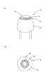
以下、実施例を用いて本発明の構成をより詳細に説明する。図1は本発明の実施例であるLEDランプ装置1を示す図である。図1aはLEDランプ装置1の上面を、図1bはLEDランプ装置1の側面を、そして図1cは図1aにおけるA−A線断面をそれぞれ示す。LEDランプ装置1は例えば車両室内用の照明(乗員の手元や足元などの照明)に利用される。
LEDランプ装置1は概略して筐体10、LEDランプ20、及びキャップ30からなる。筐体10は黒色樹脂からなり、その一端側の上面部には略筒状の突出分11が設けられている。この突出部11の内空間は、外部方向にその内径が漸増する略すり鉢状となっている。
以上のような筐体10を型成形によって作製した。
Hereinafter, the configuration of the present invention will be described in more detail using examples. FIG. 1 is a diagram showing an LED lamp device 1 according to an embodiment of the present invention. 1a shows the top surface of the LED lamp device 1, FIG. 1b shows the side surface of the LED lamp device 1, and FIG. 1c shows a cross section taken along the line AA in FIG. 1a. The LED lamp device 1 is used, for example, for vehicle interior lighting (lighting of passengers, feet, etc.).
The LED lamp device 1 generally includes a
The
図1cに示すように、筐体10の突出部11内にLEDランプ20が設置される。LEDランプ20はアンバー色発光のレンズ型LEDである。
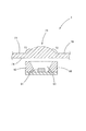
筐体10の突出部11の開口部を覆うようにキャップ30が装着される。以下図2を参照しながらキャップ30の構成を詳述する。尚、図2a及び図2bはそれぞれキャップの縦断面図及び上面図である。キャップ30はシリコーンゴム製であって、その形状は一端側が開口した略皿状である。尚、筐体10の突出部11の形状に対応するように、キャップ30の形状及び大きさ(特に内径)を設計している。
キャップ30は、平面視円形の上壁部31と、上壁部31の外縁に連続する側壁部32からなる。キャップ30の表裏各面には所定のブラスト処理が施されている。具体的には、キャップ30の表面と裏面とを複数の領域に分割し、領域ごとに以下の条件でブラスト処理を施した。
領域A:ブラスト処理1(表面処理の程度は弱)
領域B:ブラスト処理2(表面処理の程度は強)
領域C:ブラスト処理3(表面処理の程度は中)
領域D:鏡面処理
As shown in FIG. 1 c, the
A
The
Area A: Blast treatment 1 (surface treatment is weak)
Area B: Blast treatment 2 (the degree of surface treatment is strong)
Region C: Blast treatment 3 (medium degree of surface treatment)
Region D: Mirror treatment
以上の構成のキャップ30を装着したLEDランプ装置1では、LEDランプ20から放出された光が筐体突出部11の開口部を介してキャップ30に入射する。尚、筐体突出部11によってLEDランプ20の光の一部はカットされる(開口部の形状を反映した光がキャップ20に入射する)。キャップ30に入射した光は、キャップ30への入射位置及びキャップ30からの放射位置に応じて、上記のブラスト処理による光拡散作用を受ける。具体的には、キャップの中央部33(図2a及びbを参照)を通る光(以下、「中央部の光」という)はブラスト処理1による拡散作用を受けて外部放射し、キャップの中央部に隣接する部分(第1周縁部34)を通る光(以下、「第1周縁部の光」という)はブラスト処理3による拡散作用とブラスト処理1による拡散処理を受けて外部放射し、第1周縁部の外側に位置する領域(第2周縁部35)を通る光(以下、「第2周縁部の光」という)はブラスト処理3による拡散作用とブラスト処理2による拡散作用を受けて外部放射する。各光が受ける光拡散作用の強さの関係は次の通りとなる。
中央部の光<第1周縁部の光<第2周縁部の光
In the LED lamp device 1 equipped with the
Light at the center portion <Light at the first peripheral portion <Light at the second peripheral portion
ところで、キャップ30を介して外部放射した光が集合してLEDランプ装置1の照明光となるが、当該照明光において周縁部の成分を構成するのは主に、キャップ30の周縁部(第1周縁部34及び第2周縁部35)を通って外部放射した光である。この周縁部を通る光は上記のように強い拡散作用を受ける。したがって、当該光による照明領域と非照明領域との境界(即ち当該光の外周)はぼやける。このような光がその周縁部を構成することから、LEDランプ装置1の照明光の外周はぼやけたものとなる。このようにLEDランプ装置1では、外周(即ち、照明領域と非照明領域との境界)がはっきりと現れない照明光が得られる。一方、キャップ30の周縁部を通って外部放射する光は強い拡散作用を受けるため、その一部は、キャップ30の中央部33を通って外部放射する光に足し合わせられる。その結果、照明光の中央部の照度が高まる。
By the way, the light radiated outside through the
上記のように、LEDランプ装置1の照明光の周縁部を主に構成する成分は、キャップ30の周縁部を通って外部放射した光であるが、当該光が受けた拡散作用の強さは、キャップ30の中央部33に近い部分である第1周縁部34を通る場合と、キャップの中央部から離れた部分である第2周縁部35を通る場合とで異なり、前者の場合の方が弱い。このような拡散作用の違いからLEDランプ装置1の照明光では中央から周囲に向かって光の拡散度が段階的に大きくなる。これによって、拡散度が急激に変化することに起因する境界線の発生を効果的に防止できる。
尚、LEDランプ装置1では、キャップ30の中央部33にもブラスト処理が施され、上記のように当該領域を通って放出する光も拡散作用を受ける。これによって、照明光の中央部の照度の均一化が図られることとなる。
As described above, the component mainly constituting the peripheral portion of the illumination light of the LED lamp device 1 is light radiated outside through the peripheral portion of the
In the LED lamp device 1, the
本発明の他の実施例であるレンズ型LEDランプ装置2を図3に示す。尚、図3aはレンズ型LEDランプ2の斜視図であり、同図bは同上面図である。
LEDランプ2は、青系LEDの光と、レンズ(封止部材)に含有した蛍光体(黄系〜黄緑系)からの蛍光との混色によって白色光を発光する白系LEDランプである。
図3に示すように、LEDの光又は蛍光体からの蛍光が通過するレンズ50表面領域においてその周縁部には、ブラスト処理が施されている。但し、周縁部の中でもレンズ頂点に近い側の部分(第1周縁部52)と、レンズ頂点から離れた部分(第2周縁部53)のブラスト条件は異なる。具体的には例えば、第1周縁部52を上記実施例におけるブラスト処理3と同条件で処理し、第2周縁部53を上記実施例におけるブラスト処理3と同条件で処理する。
FIG. 3 shows a lens type
The
As shown in FIG. 3, a blasting process is performed on the peripheral portion of the surface region of the
以上の構成のレンズ50を備えるLEDランプ装置2では、レンズ50の上記周縁部(第1周縁部52及び第2周縁部53)を介して放射した光によって主に照明光の周縁部が構成される。ここで、レンズ50の上記周縁部(第1周縁部52及び第2周縁部53)を介して放射した光は、外部放射の際に、レンズ50表面に施されたブラスト処理による拡散処理を受ける。したがって、LEDランプ装置2の照明光の周縁部は、拡散度の高い光によって構成される。その結果、照明光の外周はぼやけたものとなる。このようにLEDランプ装置2では、外周(即ち、照明領域と非照明領域との境界)がはっきりと現れない照明光が得られる。また、以上のような拡散効果によって、照明光の周縁部における、LED自体の光と蛍光体からの蛍光との混色が促進される。その結果、照明光の周縁部における発色が良好となる。
一方、レンズ50の上記周縁部を通って外部放射する光は強い拡散作用を受けるため、その一部は、レンズ50の中央部51を通って外部放射する光に足し合わされる。その結果、照明光の中央部の照度が高まる。
In the
On the other hand, since the light radiated outside through the peripheral portion of the
上記のように、LEDランプ装置2の照明光の周縁部を主に構成する成分は、レンズ50の上記周縁部を通って外部放射した光であるが、当該光が受けた拡散作用の強さは、レンズ50の頂点に近い部分である第1周縁部52を通る場合と、レンズ50の頂点から離れた部分である第2周縁部53を通る場合とで異なり、前者の場合の方が弱い。このような拡散作用の違いからLEDランプ装置2の照明光では中央から周囲に向かって光の拡散度が段階的に大きくなる。これによって、拡散度が急劇に変化することに起因する境界線の発生を効果的に防止できる。
As described above, the component that mainly constitutes the peripheral portion of the illumination light of the
図4に本発明の他の実施例を示す。この実施例はSMDタイプのLEDとレンズとを組み合わせたLEDランプ装置3である。LEDランプ装置3は、LED60の光放出側を覆うように配置されるレンズ70を備える。LED60は、すり鉢状のリフレクタ62に取り囲まれるように配置された青系LED61を内蔵する。リフレクタ62によって囲まれる空間には黄緑系の蛍光体(図示せず)を含有した封止部材63(例えばエポキシ樹脂)が充填されている。LED60では、LED61の光の一部が蛍光体の励起に利用され、LED61からの光(青色)と、蛍光体からの蛍光(黄緑色)との混色によって白色光が得られる。
レンズ70はアクリル系樹脂からなる。レンズ70において、LED60の光が照射する位置には凸レンズ部71が形成されている。凸レンズ部71の外表面の周縁部72にはブラスト処理が施される(具体的には例えば、当該周縁部72を上記実施例1におけるブラスト処理3と同条件で処理する)。
以上の構成のLEDランプ装置3では、LED60から放出された光は凸レンズ部71を介して外部放射する。凸レンズ部71を通過する際に受けるレンズ作用によって、照明光(外部放射光)は照明領域の絞られた(収斂した)光となる。照明光の周縁部は主に、凸レンズ部71の周縁部72を介して放射した光によって構成される。ここで、凸レンズ部71の周縁部72を介して放射した光は、外部放射の際に、凸レンズ部71表面に施されたブラスト処理による拡散作用を受ける。したがって、LEDランプ装置3の照明光の周縁部は、拡散度の高い光によって構成される。その結果、照明光の外周はぼやけたものとなる。このようにLEDランプ装置3では、外周(即ち、照明領域と非照明領域との境界)がはっきりと現れない照明光が得られる。また、以上のような拡散効果によって、照明光の周縁部における、LED60自体の光と蛍光体からの蛍光との混色が促進される。その結果、照明光の周縁部における発色が良好となる。
一方、凸レンズ部71の周縁部72を通って外部放射する光は強い拡散作用を受けるため、その一部は、凸レンズ部71の中央部を通って外部放射する光に足し合わされる。その結果、照明光の中央部の照度が高まる。
FIG. 4 shows another embodiment of the present invention. This embodiment is an
The
In the
On the other hand, the light radiated outside through the
LEDランプ装置3では凸レンズ部71の周縁部72全体に一様な強さのブラスト処理を施したが、上記実施例1又は2のように、凸レンズ部71の中央部からの距離の違いによって周縁部72を複数の領域にわけ、凸レンズ部71の中央部に近い領域から遠い領域に向かって各領域に施すブラスト処理の程度が次第に強くなるようにブラスト処理を施すことにしてもよい。このような構成を採用すれば、外部放射光において、凸レンズ部71の中央部を介して外部放射した光に起因する成分(主に外部放射光の中央部を構成する)と、凸レンズ部71の周縁部を介して外部放射した光に起因する成分(主に外部放射光の周縁部を構成する)との境界において拡散度の急劇な変化がなくなり、両成分の間に境界線が観察されることを効果的に防止できる。
また、LEDランプ装置3では、レンズ70の外表面(光放射面)の所定領域にブラスト処理を施すこととしたが、これに代えて又はこれに加えてレンズ70の内表面(光導入面)の所定領域にブラスト処理を施すことにしてもよい。
また、凸レンズ部71の中央部を介して外部放射する光についても光拡散作用を受けるように、凸レンズ部71の中央部の外表面及び/又は内表面にもブラスト処理を施すことにしてもよい。
更には、レンズ70において凸レンズ部71以外の部分にもブラスト処理を施すことにしてもよい。
In the
In the
In addition, the outer surface and / or the inner surface of the central portion of the
Further, the blasting process may be performed on the
本発明のLEDランプ装置は、スポットライト的な照明光が必要とされる広範な用途に利用することができる。例えば自動車などの車両における室内照明装置として好適な利用が図られる。 The LED lamp device of the present invention can be used in a wide range of applications that require spotlight-like illumination light. For example, it can be suitably used as an indoor lighting device in a vehicle such as an automobile.
この発明は、上記発明の実施の形態及び実施例の説明に何ら限定されるものではない。特許請求の範囲の記載を逸脱せず、当業者が容易に想到できる範囲で種々の変形態様もこの発明に含まれる。
本明細書の中で明示した論文、公開特許公報、及び特許公報などの内容は、その全ての内容を援用によって引用することとする。
The present invention is not limited to the description of the embodiments and examples of the invention described above. Various modifications may be included in the present invention as long as those skilled in the art can easily conceive without departing from the description of the scope of claims.
The contents of papers, published patent gazettes, patent gazettes, and the like specified in this specification are incorporated by reference in their entirety.
次の事項を開示する。
(1)前記周縁部分において、その外縁に近づくにつれて段階的又は連続的に光拡散効果が高くなるように前記光拡散処理が施されている、請求項10に記載のLEDランプ装置。
(2)前記光拡散処理が、前記光拡散部材の表面に形成された微細な凹凸からなる、請求項9又は(1)に記載のLEDランプ装置。
(3)前記光拡散部材において、前記LEDの光が通過する領域における中央部分に、前記周縁部分に施された光拡散処理よりも光拡散効果の小さい光拡散処理が施されている請求項10、(1)、及び(2)のいずれかに記載のLEDランプ装置。
(4)前記光拡散部材が、色素、蛍光体、その他の色変換材料を含有する、請求項10、(1)、(2)、及び(3)のいずれかに記載のLEDランプ装置。
(5)前記LEDの光が照射する位置に、前記LEDの光を受けて蛍光を発する蛍光体を更に備える、請求項10、(1)、(2)、(3)、及び(4)のいずれかに記載のLEDランプ装置。
(6)前記LEDが青系のLEDであって、前記蛍光体が黄系〜黄緑系の蛍光体である、(5)に記載のLEDランプ装置。
(11)前記周縁部分において、その外縁に近づくにつれて段階的又は連続的に光拡散効果が高くなるように前記光拡散処理が施されている、請求項11に記載のLEDランプ装置。
(12)前記光拡散処理が、前記光拡散部材の表面に形成された微細な凹凸からなる、請求項11又は(11)に記載のLEDランプ装置。
(13)前記光拡散部材において、前記LEDの光が通過する領域における中央部分に、前記周縁部分に施された光拡散処理よりも光拡散効果の小さい光拡散処理が施されている請求項11、(11)、及び(12)のいずれかに記載のLEDランプ装置。
(14)前記光拡散部材が、色素、蛍光体、その他の色変換材料を含有する、請求項11、(11)、(12)、及び(13)のいずれかに記載のLEDランプ装置。
(15)前記LEDの光が照射する位置に、前記LEDの光を受けて蛍光を発する蛍光体を更に備える、請求項10、(11)、(12)、(13)、及び(14)のいずれかに記載のLEDランプ装置。
(16)前記LEDが青系のLEDであって、前記蛍光体が黄系〜黄緑系の蛍光体である、(15)に記載のLEDランプ装置。
(21)前記光拡散処理が、前記光拡散部材の表面に形成された微細な凹凸からなる、請求項12又は13に記載のLEDランプ装置。
(22)前記光拡散部材において、前記LEDの光が通過する領域における周縁部分に、前記中央部分に施された光拡散処理よりも光拡散効果の小さい光拡散処理が施されている請求項12、請求項13、及び(21)のいずれかに記載のLEDランプ装置。
(23)前記光拡散部材が、色素、蛍光体、その他の色変換材料を含有する、請求項12、請求項13、(21)、及び(22)のいずれかに記載のLEDランプ装置。
(24)前記光拡散部材が、前記LEDを内包している、請求項12、請求項13、(21)、(22)、及び(23)のいずれかに記載のLEDランプ装置。
(25)前記LEDの光が照射する位置に、前記LEDの光を受けて蛍光を発する蛍光体を更に備える、請求項12、請求項13、(21)、(22)、(23)、及び(24)のいずれかに記載のLEDランプ装置。
(26)前記LEDが青系のLEDであって、前記蛍光体が黄系〜黄緑系の蛍光体である、(25)に記載のLEDランプ装置。
The following matters are disclosed.
(1) The LED lamp device according to
(2) The LED lamp device according to (9) or (1), wherein the light diffusion treatment includes fine unevenness formed on a surface of the light diffusion member.
(3) In the light diffusing member, a light diffusing process having a light diffusing effect smaller than that of the light diffusing process performed on the peripheral portion is applied to a central portion in a region through which the light of the LED passes. The LED lamp device according to any one of (1) and (2).
(4) The LED lamp device according to any one of
(5) The device according to any one of
(6) The LED lamp device according to (5), wherein the LED is a blue LED, and the phosphor is a yellow to yellow-green phosphor.
(11) The LED lamp device according to
(12) The LED lamp device according to (11) or (11), wherein the light diffusion treatment includes fine unevenness formed on a surface of the light diffusion member.
(13) In the light diffusing member, a light diffusing process having a light diffusing effect smaller than that of the light diffusing process performed on the peripheral portion is applied to a central portion in a region where the light of the LED passes. The LED lamp device according to any one of (11) and (12).
(14) The LED lamp device according to any one of
(15) The phosphor of
(16) The LED lamp device according to (15), wherein the LED is a blue LED, and the phosphor is a yellow to yellow-green phosphor.
(21) The LED lamp device according to (12) or (13), wherein the light diffusion treatment is formed of fine irregularities formed on a surface of the light diffusion member.
(22) In the light diffusing member, a light diffusing process having a light diffusing effect smaller than that of the light diffusing process performed on the central portion is performed on a peripheral portion in a region where the light of the LED passes. The LED lamp device according to any one of claims 13 and (21).
(23) The LED lamp device according to any one of claims 12, 13, (21), and (22), wherein the light diffusing member contains a dye, a phosphor, and other color conversion materials.
(24) The LED lamp device according to any one of claims 12, 13, (21), (22), and (23), wherein the light diffusing member includes the LED.
(25) The phosphor of claim 12, 13, (21), (22), (23), and further comprising a phosphor that emits fluorescence upon receiving the light of the LED at a position irradiated with the light of the LED. (24) The LED lamp device according to any one of (2).
(26) The LED lamp device according to (25), wherein the LED is a blue LED, and the phosphor is a yellow to yellow-green phosphor.
1 2 3 LEDランプ装置、10 筐体、11 筐体突出部、20 LEDランプ、30 キャップ、33 キャップ中央部、34 キャップ第1周縁部、35 キャップ第2周縁部、50 レンズ、51 レンズ中央部、52 レンズ第1周縁部、53 レンズ第2周縁部、60 LEDランプ、61 LED、62 リフレクタ、63 封止樹脂、70 レンズ、71 レンズ中央部、72 レンズ周縁部 1 2 3 LED lamp device, 10 housing, 11 housing projection, 20 LED lamp, 30 cap, 33 cap central portion, 34 cap first peripheral portion, 35 cap second peripheral portion, 50 lens, 51 lens central portion , 52 Lens first peripheral part, 53 Lens second peripheral part, 60 LED lamp, 61 LED, 62 reflector, 63 Sealing resin, 70 Lens, 71 Lens central part, 72 Lens peripheral part
Claims (13)
前記LEDの光放出側に配置される光拡散部材であって、前記LEDの光に対して透過性の材料からなり、前記LEDの光が通過する領域における周縁部分に光拡散処理が施されている光拡散部材と、
を備えるLEDランプ装置。 LED,
A light diffusing member disposed on the light emitting side of the LED, made of a material that is transmissive to the LED light, and subjected to a light diffusing treatment in a peripheral portion in a region through which the LED light passes. A light diffusing member,
LED lamp device equipped with.
前記LEDの光放出側に位置する開口部を有するカバーであって、該開口部によって前記LEDの光の周縁部分をカットし、これによって該開口部の形状を反映した光を外部に放出させるカバーと、
前記開口部を覆う光拡散部材であって、前記LEDの光に対して透過性の材料からなり、前記LEDの光が通過する領域における周縁部分に光拡散処理が施されている光拡散部材と、
を備えるLEDランプ装置。 LED,
A cover having an opening located on the light emission side of the LED, wherein the opening cuts a peripheral portion of the light of the LED and thereby emits light reflecting the shape of the opening to the outside When,
A light diffusing member that covers the opening, the light diffusing member being made of a material that is transmissive to the light of the LED, and a light diffusing treatment being performed on a peripheral portion in a region through which the light of the LED passes; ,
LED lamp device equipped with.
前記LEDを内包する封止部材であって、その表面において、前記LEDの光の周縁部分が通過する領域に光拡散処理が施されている封止部材と、
を備えるLEDランプ装置。 LED,
A sealing member that includes the LED, and a sealing member that is subjected to a light diffusion treatment in a region through which a peripheral portion of the light of the LED passes,
LED lamp device equipped with.
前記LEDの光放出側に配置される光拡散部材であって、前記LEDの光に対して透過性の材料からなり、前記LEDの光が通過する領域における中央部分に光拡散処理が施されている光拡散部材と、
を備えるLEDランプ装置。 LED,
A light diffusing member disposed on the light emitting side of the LED, made of a material that is transmissive to the LED light, and subjected to a light diffusing process at a central portion in a region through which the LED light passes. A light diffusing member,
LED lamp device equipped with.
Priority Applications (2)
| Application Number | Priority Date | Filing Date | Title |
|---|---|---|---|
| JP2003422820A JP4442216B2 (en) | 2003-12-19 | 2003-12-19 | LED lamp device |
| US11/012,720 US7293889B2 (en) | 2003-12-19 | 2004-12-16 | LED lamp apparatus |
Applications Claiming Priority (1)
| Application Number | Priority Date | Filing Date | Title |
|---|---|---|---|
| JP2003422820A JP4442216B2 (en) | 2003-12-19 | 2003-12-19 | LED lamp device |
Publications (3)
| Publication Number | Publication Date |
|---|---|
| JP2005183193A true JP2005183193A (en) | 2005-07-07 |
| JP2005183193A5 JP2005183193A5 (en) | 2008-06-19 |
| JP4442216B2 JP4442216B2 (en) | 2010-03-31 |
Family
ID=34736226
Family Applications (1)
| Application Number | Title | Priority Date | Filing Date |
|---|---|---|---|
| JP2003422820A Expired - Fee Related JP4442216B2 (en) | 2003-12-19 | 2003-12-19 | LED lamp device |
Country Status (2)
| Country | Link |
|---|---|
| US (1) | US7293889B2 (en) |
| JP (1) | JP4442216B2 (en) |
Cited By (12)
| Publication number | Priority date | Publication date | Assignee | Title |
|---|---|---|---|---|
| JP2007142178A (en) * | 2005-11-18 | 2007-06-07 | Stanley Electric Co Ltd | White led lighting system |
| JP2008084989A (en) * | 2006-09-26 | 2008-04-10 | Matsushita Electric Works Ltd | Light-emitting apparatus and illumination appliance |
| JP2008243959A (en) * | 2007-03-26 | 2008-10-09 | Matsushita Electric Works Ltd | Light emitting device |
| JP2009130298A (en) * | 2007-11-27 | 2009-06-11 | Panasonic Electric Works Co Ltd | Light emitting device |
| JP2010529689A (en) * | 2007-06-14 | 2010-08-26 | クリー インコーポレイテッド | Light emitting device |
| JP2011523511A (en) * | 2008-05-29 | 2011-08-11 | クリー インコーポレイテッド | Light source that mixes light in the near field |
| WO2011156230A2 (en) * | 2010-06-08 | 2011-12-15 | Cree,Inc | Lighting devices with differential light transmission regions |
| KR101293401B1 (en) | 2010-09-24 | 2013-08-05 | 스탠리 일렉트릭 컴퍼니, 리미티드 | Light source unit and projector |
| JP2014053320A (en) * | 2008-10-24 | 2014-03-20 | Cree Inc | Lighting device, heat transfer structure and heat transfer element |
| JP2016009549A (en) * | 2014-06-23 | 2016-01-18 | パナソニックIpマネジメント株式会社 | Led unit and lighting device using the same |
| US9287469B2 (en) | 2008-05-02 | 2016-03-15 | Cree, Inc. | Encapsulation for phosphor-converted white light emitting diode |
| US11114594B2 (en) | 2007-08-24 | 2021-09-07 | Creeled, Inc. | Light emitting device packages using light scattering particles of different size |
Families Citing this family (61)
| Publication number | Priority date | Publication date | Assignee | Title |
|---|---|---|---|---|
| US7534633B2 (en) | 2004-07-02 | 2009-05-19 | Cree, Inc. | LED with substrate modifications for enhanced light extraction and method of making same |
| US9070850B2 (en) | 2007-10-31 | 2015-06-30 | Cree, Inc. | Light emitting diode package and method for fabricating same |
| US8669572B2 (en) | 2005-06-10 | 2014-03-11 | Cree, Inc. | Power lamp package |
| US20090045423A1 (en) * | 2006-01-13 | 2009-02-19 | Takashi Hashimoto | Semiconductor light-emitting device |
| US8044412B2 (en) | 2006-01-20 | 2011-10-25 | Taiwan Semiconductor Manufacturing Company, Ltd | Package for a light emitting element |
| US7675145B2 (en) | 2006-03-28 | 2010-03-09 | Cree Hong Kong Limited | Apparatus, system and method for use in mounting electronic elements |
| US11210971B2 (en) | 2009-07-06 | 2021-12-28 | Cree Huizhou Solid State Lighting Company Limited | Light emitting diode display with tilted peak emission pattern |
| US8748915B2 (en) | 2006-04-24 | 2014-06-10 | Cree Hong Kong Limited | Emitter package with angled or vertical LED |
| US7635915B2 (en) | 2006-04-26 | 2009-12-22 | Cree Hong Kong Limited | Apparatus and method for use in mounting electronic elements |
| JP2009538536A (en) | 2006-05-26 | 2009-11-05 | クリー エル イー ディー ライティング ソリューションズ インコーポレイテッド | Solid state light emitting device and method of manufacturing the same |
| EP1878965A1 (en) * | 2006-06-23 | 2008-01-16 | Kuang-Hung Kao | Outdoor lamp with luminescence efficiency |
| US8735920B2 (en) | 2006-07-31 | 2014-05-27 | Cree, Inc. | Light emitting diode package with optical element |
| US7804147B2 (en) | 2006-07-31 | 2010-09-28 | Cree, Inc. | Light emitting diode package element with internal meniscus for bubble free lens placement |
| US8367945B2 (en) | 2006-08-16 | 2013-02-05 | Cree Huizhou Opto Limited | Apparatus, system and method for use in mounting electronic elements |
| US7654695B1 (en) * | 2006-08-22 | 2010-02-02 | Avaya Inc. | Pigmented collar for bi-color light emitting diodes |
| JP4823866B2 (en) * | 2006-11-13 | 2011-11-24 | 株式会社小糸製作所 | Light emitting module for vehicular lamp |
| US7769066B2 (en) | 2006-11-15 | 2010-08-03 | Cree, Inc. | Laser diode and method for fabricating same |
| US7813400B2 (en) | 2006-11-15 | 2010-10-12 | Cree, Inc. | Group-III nitride based laser diode and method for fabricating same |
| EP2095018A1 (en) | 2006-12-04 | 2009-09-02 | Cree Led Lighting Solutions, Inc. | Lighting device and lighting method |
| US9310026B2 (en) | 2006-12-04 | 2016-04-12 | Cree, Inc. | Lighting assembly and lighting method |
| US7834367B2 (en) | 2007-01-19 | 2010-11-16 | Cree, Inc. | Low voltage diode with reduced parasitic resistance and method for fabricating |
| US9711703B2 (en) | 2007-02-12 | 2017-07-18 | Cree Huizhou Opto Limited | Apparatus, system and method for use in mounting electronic elements |
| CN101303428A (en) * | 2007-05-08 | 2008-11-12 | 鸿富锦精密工业(深圳)有限公司 | Back light module unit and optical plate thereof |
| WO2009012287A1 (en) | 2007-07-17 | 2009-01-22 | Cree Led Lighting Solutions, Inc. | Optical elements with internal optical features and methods of fabricating same |
| US9012937B2 (en) | 2007-10-10 | 2015-04-21 | Cree, Inc. | Multiple conversion material light emitting diode package and method of fabricating same |
| USD615504S1 (en) | 2007-10-31 | 2010-05-11 | Cree, Inc. | Emitter package |
| US8866169B2 (en) | 2007-10-31 | 2014-10-21 | Cree, Inc. | LED package with increased feature sizes |
| US10256385B2 (en) | 2007-10-31 | 2019-04-09 | Cree, Inc. | Light emitting die (LED) packages and related methods |
| USD633631S1 (en) | 2007-12-14 | 2011-03-01 | Cree Hong Kong Limited | Light source of light emitting diode |
| USD634863S1 (en) | 2008-01-10 | 2011-03-22 | Cree Hong Kong Limited | Light source of light emitting diode |
| JP5279329B2 (en) * | 2008-04-24 | 2013-09-04 | パナソニック株式会社 | Light-emitting unit with lens |
| US8049230B2 (en) * | 2008-05-16 | 2011-11-01 | Cree Huizhou Opto Limited | Apparatus and system for miniature surface mount devices |
| US8791471B2 (en) | 2008-11-07 | 2014-07-29 | Cree Hong Kong Limited | Multi-chip light emitting diode modules |
| US8368112B2 (en) | 2009-01-14 | 2013-02-05 | Cree Huizhou Opto Limited | Aligned multiple emitter package |
| KR101243826B1 (en) * | 2009-02-17 | 2013-03-18 | 엘지디스플레이 주식회사 | Light Emitting Diode Pakage, Method for Manufacturing the Same and Light Source Unit Having the LED Pakage |
| US8415692B2 (en) | 2009-07-06 | 2013-04-09 | Cree, Inc. | LED packages with scattering particle regions |
| FR2954458B1 (en) * | 2009-12-21 | 2012-03-02 | Fd Dev | HUBLOT TYPE LAMP |
| US8350370B2 (en) | 2010-01-29 | 2013-01-08 | Cree Huizhou Opto Limited | Wide angle oval light emitting diode package |
| IT1401974B1 (en) * | 2010-09-28 | 2013-08-28 | Università Degli Studi Di Milano Bicocca | LIGHTING DEVICE |
| US8455882B2 (en) | 2010-10-15 | 2013-06-04 | Cree, Inc. | High efficiency LEDs |
| DE102011015405A1 (en) * | 2011-03-29 | 2012-10-04 | Osram Opto Semiconductors Gmbh | Optical element and radiation-emitting device with such an optical element |
| CN109065676A (en) | 2011-08-08 | 2018-12-21 | 夸克星有限责任公司 | Lighting device including a plurality of light-emitting elements |
| US9081125B2 (en) | 2011-08-08 | 2015-07-14 | Quarkstar Llc | Illumination devices including multiple light emitting elements |
| US8564004B2 (en) | 2011-11-29 | 2013-10-22 | Cree, Inc. | Complex primary optics with intermediate elements |
| US9746173B2 (en) | 2012-09-13 | 2017-08-29 | Quarkstar Llc | Illumination devices including enclosure panels with luminaire modules |
| CN104755832B (en) | 2012-09-13 | 2018-12-21 | 夸克星有限责任公司 | The lighting system directly or indirectly illuminated is provided |
| US20150359072A1 (en) * | 2012-12-31 | 2015-12-10 | Direct Result Group, LLC | Piling light |
| US9206956B2 (en) | 2013-02-08 | 2015-12-08 | Quarkstar Llc | Illumination device providing direct and indirect illumination |
| EP3270041B1 (en) | 2013-04-19 | 2019-07-10 | Quarkstar LLC | Illumination devices with adjustable optical elements |
| US9335462B2 (en) | 2013-07-18 | 2016-05-10 | Quarkstar Llc | Luminaire module with multiple light guide elements |
| WO2015042174A1 (en) | 2013-09-17 | 2015-03-26 | Quarkstar Llc | Light guide illumination device with light divergence modifier |
| US9601670B2 (en) | 2014-07-11 | 2017-03-21 | Cree, Inc. | Method to form primary optic with variable shapes and/or geometries without a substrate |
| US9534741B2 (en) | 2014-07-23 | 2017-01-03 | Cree, Inc. | Lighting devices with illumination regions having different gamut properties |
| US10622522B2 (en) | 2014-09-05 | 2020-04-14 | Theodore Lowes | LED packages with chips having insulated surfaces |
| US10180248B2 (en) | 2015-09-02 | 2019-01-15 | ProPhotonix Limited | LED lamp with sensing capabilities |
| US10637575B2 (en) * | 2016-05-25 | 2020-04-28 | Wisconsin Alumni Research Foundation | Spatial location indoors using standard fluorescent fixtures |
| JP6418200B2 (en) | 2016-05-31 | 2018-11-07 | 日亜化学工業株式会社 | Light emitting device and manufacturing method thereof |
| JP6536560B2 (en) | 2016-12-27 | 2019-07-03 | 日亜化学工業株式会社 | Light emitting device and method of manufacturing the same |
| IT201800003974A1 (en) * | 2018-03-26 | 2019-09-26 | Osram Gmbh | SILICONE DIFFUSER AND PRODUCTION METHOD TO MAKE THE DIFFUSER |
| US10995936B1 (en) | 2018-07-13 | 2021-05-04 | Volt, LLC | Fully adjustable landscape lighting system |
| US11079534B2 (en) | 2018-07-30 | 2021-08-03 | Valeo North America, Inc. | LED coupler for light reflection and leakage prevention |
Family Cites Families (19)
| Publication number | Priority date | Publication date | Assignee | Title |
|---|---|---|---|---|
| US3821590A (en) * | 1971-03-29 | 1974-06-28 | Northern Electric Co | Encapsulated solid state light emitting device |
| US4164012A (en) * | 1977-06-17 | 1979-08-07 | Koehler Manufacturing Company | Luminaire apparatus for reflecting radiant energy and methods of controlling characteristics of reflected radiant energy |
| US4599537A (en) * | 1982-04-30 | 1986-07-08 | Shigeaki Yamashita | IR light emitting apparatus with visible detection means |
| GB8915167D0 (en) * | 1989-07-01 | 1989-08-23 | Oxley Dev Co Ltd | A sealed led lamp housing |
| JPH07270603A (en) * | 1994-03-29 | 1995-10-20 | Enplas Corp | Optical control member |
| JPH08339704A (en) | 1995-06-12 | 1996-12-24 | Nippondenso Co Ltd | Light device for use with vehicle |
| US5820246A (en) * | 1996-02-08 | 1998-10-13 | Eaton Corporation | Display system having electroluminescent devices |
| JPH10244876A (en) * | 1997-03-04 | 1998-09-14 | Koito Mfg Co Ltd | License plate lamp |
| US6350041B1 (en) * | 1999-12-03 | 2002-02-26 | Cree Lighting Company | High output radial dispersing lamp using a solid state light source |
| JP3908428B2 (en) | 2000-01-06 | 2007-04-25 | 株式会社小糸製作所 | Vehicle sign light |
| TW465123B (en) * | 2000-02-02 | 2001-11-21 | Ind Tech Res Inst | High power white light LED |
| US6328456B1 (en) * | 2000-03-24 | 2001-12-11 | Ledcorp | Illuminating apparatus and light emitting diode |
| JP2002049324A (en) * | 2000-07-31 | 2002-02-15 | Nippon Seiki Co Ltd | Back light device |
| US6733147B2 (en) * | 2000-09-07 | 2004-05-11 | San Zhuang Wang | Backlighting system for displays |
| US6592238B2 (en) * | 2001-01-31 | 2003-07-15 | Light Technologies, Inc. | Illumination device for simulation of neon lighting |
| JP3891115B2 (en) * | 2001-04-17 | 2007-03-14 | 日亜化学工業株式会社 | Light emitting device |
| JP2003234509A (en) * | 2002-02-08 | 2003-08-22 | Citizen Electronics Co Ltd | Light emitting diode |
| US6932496B2 (en) * | 2002-04-16 | 2005-08-23 | Farlight Llc | LED-based elevated omnidirectional airfield light |
| US6787999B2 (en) * | 2002-10-03 | 2004-09-07 | Gelcore, Llc | LED-based modular lamp |
-
2003
- 2003-12-19 JP JP2003422820A patent/JP4442216B2/en not_active Expired - Fee Related
-
2004
- 2004-12-16 US US11/012,720 patent/US7293889B2/en active Active
Cited By (19)
| Publication number | Priority date | Publication date | Assignee | Title |
|---|---|---|---|---|
| JP2007142178A (en) * | 2005-11-18 | 2007-06-07 | Stanley Electric Co Ltd | White led lighting system |
| JP2008084989A (en) * | 2006-09-26 | 2008-04-10 | Matsushita Electric Works Ltd | Light-emitting apparatus and illumination appliance |
| JP2008243959A (en) * | 2007-03-26 | 2008-10-09 | Matsushita Electric Works Ltd | Light emitting device |
| JP2012256936A (en) * | 2007-06-14 | 2012-12-27 | Cree Inc | Light-emitting device |
| JP2010529689A (en) * | 2007-06-14 | 2010-08-26 | クリー インコーポレイテッド | Light emitting device |
| US9273830B2 (en) | 2007-06-14 | 2016-03-01 | Cree, Inc. | Light source with near field mixing |
| US11114594B2 (en) | 2007-08-24 | 2021-09-07 | Creeled, Inc. | Light emitting device packages using light scattering particles of different size |
| JP2009130298A (en) * | 2007-11-27 | 2009-06-11 | Panasonic Electric Works Co Ltd | Light emitting device |
| US9287469B2 (en) | 2008-05-02 | 2016-03-15 | Cree, Inc. | Encapsulation for phosphor-converted white light emitting diode |
| JP2011523511A (en) * | 2008-05-29 | 2011-08-11 | クリー インコーポレイテッド | Light source that mixes light in the near field |
| US8858032B2 (en) | 2008-10-24 | 2014-10-14 | Cree, Inc. | Lighting device, heat transfer structure and heat transfer element |
| US10495295B2 (en) | 2008-10-24 | 2019-12-03 | Ideal Industries Lighting Llc | Lighting device, heat transfer structure and heat transfer element |
| JP2014053320A (en) * | 2008-10-24 | 2014-03-20 | Cree Inc | Lighting device, heat transfer structure and heat transfer element |
| WO2011156230A3 (en) * | 2010-06-08 | 2012-04-12 | Cree,Inc | Lighting devices with differential light transmission regions |
| US8575836B2 (en) | 2010-06-08 | 2013-11-05 | Cree, Inc. | Lighting devices with differential light transmission regions |
| JP2013528315A (en) * | 2010-06-08 | 2013-07-08 | クリー インコーポレイテッド | Lighting device having different light transmission regions |
| WO2011156230A2 (en) * | 2010-06-08 | 2011-12-15 | Cree,Inc | Lighting devices with differential light transmission regions |
| KR101293401B1 (en) | 2010-09-24 | 2013-08-05 | 스탠리 일렉트릭 컴퍼니, 리미티드 | Light source unit and projector |
| JP2016009549A (en) * | 2014-06-23 | 2016-01-18 | パナソニックIpマネジメント株式会社 | Led unit and lighting device using the same |
Also Published As
| Publication number | Publication date |
|---|---|
| US20050152127A1 (en) | 2005-07-14 |
| JP4442216B2 (en) | 2010-03-31 |
| US7293889B2 (en) | 2007-11-13 |
Similar Documents
| Publication | Publication Date | Title |
|---|---|---|
| JP4442216B2 (en) | LED lamp device | |
| JP5431636B2 (en) | Vehicle sign light | |
| JP2005183193A5 (en) | ||
| US7329904B2 (en) | LED lamp device | |
| JP6769449B2 (en) | Lighting equipment | |
| JPH0927642A (en) | Lighting device | |
| JP4179176B2 (en) | LED lamp device | |
| KR20150125990A (en) | Turn signal for vehicle | |
| JP2006138129A (en) | Outside handle of vehicle | |
| JP6133306B2 (en) | Illumination unit with lamp shade | |
| KR102012746B1 (en) | Automobile lamp | |
| JP4122964B2 (en) | License plate lighting device | |
| JP2008021932A (en) | Light emitting device | |
| JP2005243608A (en) | Led lamp device | |
| KR20180083776A (en) | Optical lens for improvement of lightening and uniformity | |
| JP4597788B2 (en) | Infrared projector | |
| JP2004284393A (en) | License plate lighting system | |
| KR102146474B1 (en) | Lighting apparatus | |
| JP2001320091A (en) | Cap member for led and led illuminator provided with the same | |
| JP3174884U (en) | LED traffic light | |
| US20230059403A1 (en) | Wavelength conversion optics | |
| JP2001253294A (en) | Direct lighting system of meter for vehicle, and meter lens | |
| JP2009245681A (en) | Light source device | |
| JP2015002127A (en) | Lighting device | |
| JP2014067515A (en) | Lighting fixture for vehicle |
Legal Events
| Date | Code | Title | Description |
|---|---|---|---|
| A621 | Written request for application examination |
Free format text: JAPANESE INTERMEDIATE CODE: A621 Effective date: 20060426 |
|
| A521 | Request for written amendment filed |
Free format text: JAPANESE INTERMEDIATE CODE: A523 Effective date: 20080428 |
|
| A131 | Notification of reasons for refusal |
Free format text: JAPANESE INTERMEDIATE CODE: A131 Effective date: 20090414 |
|
| A521 | Request for written amendment filed |
Free format text: JAPANESE INTERMEDIATE CODE: A523 Effective date: 20090528 |
|
| A521 | Request for written amendment filed |
Free format text: JAPANESE INTERMEDIATE CODE: A523 Effective date: 20090611 |
|
| A02 | Decision of refusal |
Free format text: JAPANESE INTERMEDIATE CODE: A02 Effective date: 20090811 |
|
| A521 | Request for written amendment filed |
Free format text: JAPANESE INTERMEDIATE CODE: A523 Effective date: 20091023 |
|
| A911 | Transfer to examiner for re-examination before appeal (zenchi) |
Free format text: JAPANESE INTERMEDIATE CODE: A911 Effective date: 20091118 |
|
| TRDD | Decision of grant or rejection written | ||
| A01 | Written decision to grant a patent or to grant a registration (utility model) |
Free format text: JAPANESE INTERMEDIATE CODE: A01 Effective date: 20091222 |
|
| A01 | Written decision to grant a patent or to grant a registration (utility model) |
Free format text: JAPANESE INTERMEDIATE CODE: A01 |
|
| A61 | First payment of annual fees (during grant procedure) |
Free format text: JAPANESE INTERMEDIATE CODE: A61 Effective date: 20100104 |
|
| R150 | Certificate of patent or registration of utility model |
Ref document number: 4442216 Country of ref document: JP Free format text: JAPANESE INTERMEDIATE CODE: R150 Free format text: JAPANESE INTERMEDIATE CODE: R150 |
|
| FPAY | Renewal fee payment (event date is renewal date of database) |
Free format text: PAYMENT UNTIL: 20130122 Year of fee payment: 3 |
|
| FPAY | Renewal fee payment (event date is renewal date of database) |
Free format text: PAYMENT UNTIL: 20140122 Year of fee payment: 4 |
|
| LAPS | Cancellation because of no payment of annual fees |