JP2005183003A - Reproducing apparatus - Google Patents
Reproducing apparatus Download PDFInfo
- Publication number
- JP2005183003A JP2005183003A JP2005082170A JP2005082170A JP2005183003A JP 2005183003 A JP2005183003 A JP 2005183003A JP 2005082170 A JP2005082170 A JP 2005082170A JP 2005082170 A JP2005082170 A JP 2005082170A JP 2005183003 A JP2005183003 A JP 2005183003A
- Authority
- JP
- Japan
- Prior art keywords
- video
- disc
- data
- disk
- list
- Prior art date
- Legal status (The legal status is an assumption and is not a legal conclusion. Google has not performed a legal analysis and makes no representation as to the accuracy of the status listed.)
- Pending
Links
Images


Abstract
Description
本発明は、CD−DA(デジタルオーディオコンパクトディスク)やビデオCD等を複数枚収納して選択的に再生することのできる再生装置に関するものである。 The present invention relates to a playback apparatus capable of storing and selectively playing back a plurality of CD-DA (digital audio compact disc), video CD, and the like.
CD−DAやビデオCDなど、いわゆるROMタイプの多様なディスクメディアが普及している。CD−DAではデジタル音声データを記録して音楽等を高音質で楽しめるようにされており、またこのCD−DAの一種としてサブコードデータ内に静止画像データも記録したCD−Gも知られている。
さらにいわゆるCD−ROMの一種としてデジタル音声データとともに動画データを記録したビデオCDも開発されている。
A variety of so-called ROM type disk media such as CD-DA and video CD are in widespread use. In CD-DA, digital audio data is recorded so that music and the like can be enjoyed with high sound quality, and CD-G in which still image data is recorded in subcode data is also known as a kind of CD-DA. Yes.
Further, a video CD in which moving image data is recorded together with digital audio data has been developed as a kind of so-called CD-ROM.
また再生装置としては、1枚のディスクだけでなく複数枚のディスクを収納し、選択的に再生させることができるCDチャンジャーが開発され、このCDチャンジャーでもビデオCD対応のタイプも開発されている。 Also, as a playback device, a CD changer that can store not only one disc but also a plurality of discs and can selectively play back has been developed, and this CD changer has also been developed to be compatible with video CDs. Yes.
ところで、ビデオCDチャンジャーにおいてディスク収納部に複数のディスクを装填しておいた場合に、ユーザーはどの位置にどのディスクを入れておいたかがわからなくなることが多い。 By the way, when a plurality of discs are loaded in the disc storage unit in the video CD changer, the user often cannot know which disc has been placed in which position.
通常、再生させるディスクの選択は、ユーザーは収納位置の指定により行なう。例えば複数のトレイを有するものではトレイ番号をディスク番号とし、ユーザーが『ディスク2』の再生操作を行なった場合は、第2のトレイに搭載されているディスクが選択されて再生されることになる。
このため、ユーザーはどの収納位置にどのディスクが入れられているかを認識できなければ、操作時に非常に不便を感じることになる。
Normally, the user selects the disc to be played by specifying the storage position. For example, in the case of having a plurality of trays, if the tray number is the disk number and the user performs the playback operation of “
For this reason, if the user cannot recognize which disc is in which storage position, the user will feel very inconvenient during the operation.
本発明はこのような問題点を解消するとともに、特にビデオCDなどの映像が記録されたディスクについてはその映像内容がわかるようにすることが好適なため、収納された各ディスクについて映像を抽出し、各ディスクの内容を一覧表示するダイジェスト映像を得るようにして、ユーザーがこれを見ることで操作性を向上させるようにすることを目的とする。 The present invention solves such problems, and it is preferable that the contents of a video such as a video CD be recorded, so that the video content is extracted. An object of the present invention is to obtain a digest video that displays a list of the contents of each disc and to improve the operability by allowing the user to view the digest video.
このため、映像またはオーディオデータが記録されたディスクを複数収納可能な収納手段と、収納手段に収納された複数のディスクから所望のディスクを選択する選択手段と、収納手段に収納された各々のディスクから映像データを読み出す再生手段と、再生手段にて再生された、収納手段に収納された各々のディスクの映像データを同一画面上に表示できるように制御する映像出力制御手段と、映像出力制御手段によって表示された同一画面上の各々のディスクの映像データから所定のディスクに対応する映像データを選択する第1の操作手段と、第1の操作手段にて選択された所定のディスクに対応する映像データの早送り再生を指示する第2の操作手段と、第2の操作手段の早送り再生操作に応じて、上記第1の操作手段にて選択された所定のディスクの映像データの早送り再生を行うように再生手段を制御する制御手段と、を備え、再生手段にて早送り再生された映像データを上記第1の操作手段にて選択された所定のディスクに対応する表示領域に表示するようにする。 Therefore, storage means capable of storing a plurality of disks on which video or audio data is recorded, selection means for selecting a desired disk from the plurality of disks stored in the storage means, and each of the disks stored in the storage means Reproduction means for reading out the video data from the video, video output control means for controlling the video data of each disk stored in the storage means and reproduced by the reproduction means to be displayed on the same screen, and video output control means The first operation means for selecting video data corresponding to a predetermined disk from the video data of each disk displayed on the same screen, and the video corresponding to the predetermined disk selected by the first operation means The second operating means for instructing fast-forward playback of data, and the first operating means selected according to the fast-forward playback operation of the second operating means. Control means for controlling reproduction means to perform fast-forward reproduction of video data on a predetermined disk, and the predetermined disk selected by the first operation means for video data reproduced in fast-forward by the reproduction means To be displayed in the display area corresponding to.
本発明の再生装置は、収納されたそれぞれのディスクからの映像が一画面内で表示されるダイジェスト映像データを生成し出力することにより、接続されたモニタ装置上のダイジェスト映像でユーザーは各ディスクの内容を確認できるという効果がある。これによりユーザーは再生させたいディスクの指定操作に迷うことはなくなり、操作性は大きく向上する。 The playback device of the present invention generates and outputs digest video data in which video from each stored disc is displayed within one screen, so that the user can use the digest video on the connected monitor device. There is an effect that the contents can be confirmed. As a result, the user does not hesitate to specify the disc to be reproduced, and the operability is greatly improved.
ダイジェスト映像データ出力時にディスクの早送り再生を実行させ、その早送り再生データをダイジェスト映像データに組み込んで、ダイジェスト映像表示内で早送り映像を出力させることで、ユーザーはディスクの内容について短時間でより詳しく確認することができる。
特に、この早送り再生を各ディスクについて順次実行させることで、全ディスクについて詳しい内容確認ができるという効果がある。
また、特定のディスクのみを選択してダイジェスト映像表示内で早送り再生させることで、ユーザーが内容をより詳しく確認したいディスクについてのみ、より短時間で確認できるという効果が生ずる。
When the digest video data is output, the fast-forward playback of the disc is executed, the fast-forward playback data is incorporated into the digest video data, and the fast-forward video is output in the digest video display so that the user can check the contents of the disc in more detail in a short time. can do.
In particular, this fast-forward playback is sequentially executed for each disk, so that there is an effect that detailed contents can be confirmed for all the disks.
Further, by selecting only a specific disk and performing fast-forward playback within the digest video display, only the disk for which the user wants to confirm the contents in more detail can be confirmed in a shorter time.
以下、本発明の実施例としてビデオCDとCD−DA(デジタルオーディオCD及びCD−G)について映像/音声の再生が可能とされた再生装置を説明する。ビデオCDとしてはプレイバックコントロール機能の付加されたものが存在するが、本実施例ではこれにも対応する再生装置とする。
説明は以下の順序で行なう。
Hereinafter, as an embodiment of the present invention, a reproducing apparatus capable of reproducing video / audio for a video CD and a CD-DA (digital audio CD and CD-G) will be described. Some video CDs are provided with a playback control function. In this embodiment, a playback apparatus is also provided.
The description will be given in the following order.
[I.ビデオCDのデータ構造]
1.データ形態。
a.ビデオデータ。
b.オーディオデータ。
c.管理データ。
2.トラック構造。
3.セクター構造。
4.ディスク上の配置。
5.TOC及びサブコード。
6.ディレクトリ構造。
7.ビデオCDデータトラック。
a.PVD(基本ボリューム記述子)。
b.ビデオCDインフォメーション。
−b1− ディスクインフォメーション。
−b2− エントリーテーブル。
−b3− リストIDオフセットテーブル。
−b4− PSD(プレイシーケンスディスクリプタ)。
* プレイリスト。
* セレクションリスト。
* エンドリスト。
c.セグメントプレイアイテム。
[I. Data structure of video CD]
1. Data form.
a. Video data.
b. Audio data.
c. Management data.
2. Track structure.
3. Sector structure.
4). Placement on disk.
5). TOC and subcode.
6). Directory structure.
7). Video CD data track.
a. PVD (Basic Volume Descriptor).
b. Video CD information.
-B1- Disc information.
-B2- Entry table.
-B3- List ID offset table.
-B4- PSD (play sequence descriptor).
* playlist.
* Selection list.
* End list.
c. Segment play item.
[II.プレイバックコントロール(PBC)]。
1 リスト構造。
2 具体例。
[ III.再生装置の構成]。
1 外観。
2 回路ブロック。
[II. Playback control (PBC)].
1 List structure.
2 Specific example.
[III. Configuration of playback apparatus].
1 Appearance.
2 Circuit block.
[IV.オールディスクダイジェスト動作]。
1 第1の動作処理例。
2 第2の動作処理例。
[V.オールディスクダイジェスト表示時の早送り動作]。
1 第1の動作処理例。
2 第2の動作処理例。
[IV. All disk digest operation].
1 First operation processing example.
2 Second operation processing example.
[V. Fast-forward operation when all disk digest is displayed].
1 First operation processing example.
2 Second operation processing example.
[I.ビデオCDのデータ構造]
1.データ形態
ビデオCD規格は、高能率符号化技術として標準化されたMPEG方式を応用し、CD−ROMディスクから60分以上の動画像及び音声を再生することができるようにしたものである。これにより音楽、映画、カラオケなどの家庭用ソフトウエアとして有用であるとともに、さらに、静止画も組み合わせて教育ソフト、電子出版ソフト、ゲームソフトなどにも対応可能とされる。
このビデオCDでは、動画データについてはMPEG方式でデータ圧縮するとともに、この動画データを圧縮したオーディオデータに多重化して記録している。さらに、所定の領域には再生に必要な管理データが記録されている。
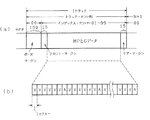
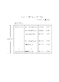
図13にビデオCD(XA仕様)のデータのフォーマットを示している。
[I. Data structure of video CD]
1. Data format
The video CD standard applies the MPEG system standardized as a high-efficiency encoding technique, and is capable of reproducing moving images and audio of 60 minutes or more from a CD-ROM disc. This makes it useful as home software for music, movies, karaoke, etc., and can also be used for educational software, electronic publishing software, game software, etc. by combining still images.
In this video CD, moving image data is compressed by the MPEG method, and the moving image data is multiplexed and recorded on the compressed audio data. Further, management data necessary for reproduction is recorded in a predetermined area.
FIG. 13 shows the data format of a video CD (XA specification).
a.ビデオデータ
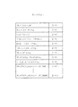
画像とオーディオの記録フォーマットとしては、図13からわかるようにビデオデータに1.152Mbit/秒、オーディオデータに 64Kbit/秒〜384Kbit/秒が割り当てられている。ビデオデータ(動画)の画素寸法は、NTSC信号(29.97Hz) 及びフィルム(23.976Hz)の場合は352×240画素、PAL信号(25Hz)の場合は352×288画素となり、即ち図15のようになる。
また、静止画の画素数としては、NTSC方式の場合、標準レベルで352×240画素、高精細レベルで704×480画素とされる。PAL方式の場合は、標準レベルで352×288画素、高精細レベルで704×576画素とされる。
a. Video data
As shown in FIG. 13, 1.152 Mbit / second is assigned to video data and 64 Kbit / second to 384 Kbit / second is assigned to audio data as the image and audio recording formats. The pixel size of the video data (moving image) is 352 × 240 pixels in the case of NTSC signal (29.97 Hz) and film (23.976 Hz), and 352 × 288 pixels in the case of PAL signal (25 Hz), that is, as shown in FIG. Become.
In the NTSC system, the number of pixels of the still image is 352 × 240 pixels at the standard level and 704 × 480 pixels at the high definition level. In the case of the PAL system, the standard level is 352 × 288 pixels, and the high definition level is 704 × 576 pixels.
MPEG方式によるビデオデータ(動画)の圧縮符号化は次のように行なわれる。圧縮前の映像信号をNTSC方式とすると、このNTSC方式の場合1秒間が30フレームの映像信号により構成される。
MPEG方式では、各映像信号(1フレーム)に対して平面方向にブロック分け(横22ブロック分割、縦15ブロック分割で、330ブロック)を行ない、各ブロックのデータをDCT変換し、さらにビット数を減らすために再量子化を行なう(高域成分を0にする)。そして、ブロックを1フレームの画面左上となるブロックからジグザグとなるようにブロック順を並び代え、ランレングスコーディングを行なってさらにビット数の圧縮を行なうようにしている。
The compression encoding of video data (moving image) by the MPEG system is performed as follows. Assuming that the video signal before compression is the NTSC system, in the case of this NTSC system, one second is composed of a video signal of 30 frames.
In the MPEG system, each video signal (one frame) is divided into blocks in the plane direction (divided into 22 blocks in the horizontal direction and 330 blocks in the vertical 15 block division), the data of each block is DCT converted, and the number of bits is further changed. In order to reduce, requantization is performed (high frequency component is set to 0). Then, the block order is rearranged so that the blocks are zigzag from the block on the upper left of the screen of one frame, and run-length coding is performed to further compress the number of bits.
このように圧縮処理される映像信号の各フレームについては、その時間的に前後となるフレームでは映像情報として非常に似たものであり、これを利用してさらに情報の圧縮が行なわれ、圧縮度の異なる3種類の映像データ(1フレームの映像データ)が設けられる。これらは、Iピクチャー(Intra Picture) 、Pピクチャー(Predicted Picture) ,Bピクチャー(Bidirectionally predicted Picture) と呼ばれる。 Each frame of the video signal to be compressed in this way is very similar to the video information in the frames before and after that, and this is used to further compress the information. Are provided with three types of video data (one frame of video data). These are called an I picture (Intra Picture), a P picture (Predicted Picture), and a B picture (Bidirectionally predicted Picture).
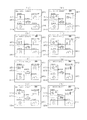
そして、1秒間についての30枚の各フレームついて、一般的には図14(a)のようにIピクチャー,Pピクチャー,Bピクチャーが並ぶことになる。例えばこの場合、15フレーム間隔のフレームがIピクチャーI1 ,I2 とされ、また、8枚のPピクチャーP1 〜P8 、及び20枚のBピクチャーB1 〜B20がそれぞれ図示のように配置される。あるIピクチャーから次のIピクチャーの前のフレームに至る区間をGOP(Group of Picture)と呼ぶ。 In general, an I picture, a P picture, and a B picture are arranged as shown in FIG. 14A for each of the 30 frames per second. For example, in this case, the frames at intervals of 15 frames are I pictures I 1 and I 2, and eight P pictures P 1 to P 8 and 20 B pictures B 1 to B 20 are respectively shown in the figure. Be placed. A section from one I picture to a frame before the next I picture is called a GOP (Group of Picture).
Iピクチャーは上記したようにDCT変換により符合化された正規の画像データである。
Pピクチャーは図14(b)のように、最も近いIピクチャー又はPピクチャーから、動き補償を用いて符合化されて生成される。例えばPピクチャーP1 はIピクチャーI1 を用いて、また、PピクチャーP2 はPピクチャーP1 を用いて生成される。
このため、PピクチャーはIピクチャーより圧縮されたものとなる。なお、順次前のIピクチャー又はPピクチャーから生成するため、エラーが生ずると、エラーが伝搬してしまうことになる。
The I picture is normal image data encoded by DCT conversion as described above.
As shown in FIG. 14B, the P picture is generated by encoding from the nearest I picture or P picture using motion compensation. For example, P picture P 1 is generated using I picture I 1 , and P picture P 2 is generated using P picture P 1 .
Therefore, the P picture is more compressed than the I picture. In addition, since it produces | generates from the previous I picture or P picture sequentially, if an error arises, an error will propagate.
Bピクチャーは、図14(c)のように過去及び未来の両方のIピクチャー又はPピクチャーを用いて生成される。
例えばBピクチャーB1 ,B2 はIピクチャーI1 とPピクチャーP1 を用いて生成され、BピクチャーB3 ,B4 はPピクチャーP1 とPピクチャーP2 を用いて生成される。
Bピクチャーは最も圧縮されたデータとなる。また、データ生成レファレンスとはならないため、エラーが伝搬されることはない。
The B picture is generated using both past and future I pictures or P pictures as shown in FIG.
For example, B pictures B 1 and B 2 are generated using I picture I 1 and P picture P 1 , and B pictures B 3 and B 4 are generated using P picture P 1 and P picture P 2 .
The B picture is the most compressed data. Moreover, since it is not a data generation reference, no error is propagated.
MPEGのアルゴリズムでは、Iピクチャーの位置や同期を選択することが許されており、この選択はランダムアクセス度やシーンカット等の事情から決定される。例えばランダムアクセスを重視すれば、図14(a)のように少なくとも1秒間に2枚のIピクチャーが必要となる。
さらに、Pピクチャー、Bピクチャーの頻度も選択可能であり、これはエンコード手段のメモリー容量などに応じて設定されるものである。
In the MPEG algorithm, it is allowed to select the position and synchronization of the I picture, and this selection is determined from circumstances such as the degree of random access and scene cut. For example, if importance is attached to random access, at least two I pictures are required per second as shown in FIG.
Furthermore, the frequency of the P picture and B picture can be selected, and this is set according to the memory capacity of the encoding means.
また、MPEG方式におけるエンコード手段は、デコーダにおいて効率が良くなるように映像データストリームを再配置して出力するようにしている。
例えば図14(a)の場合において、表示すべきフレーム順序(デコーダ出力順序)は、図14(a)下部に示したフレーム番号どおりとなるが、デコーダがBピクチャーを再合成するためにBピクチャーより前時点でレファレンスとなるPピクチャーが必要となる。このためエンコーダ側では、図14(d)のフレーム順序を図14(e)のように並べ換えて、これを映像データストリームとして伝送するようにしている。
Also, the encoding means in the MPEG system rearranges and outputs the video data stream so as to improve the efficiency in the decoder.
For example, in the case of FIG. 14 (a), the frame order to be displayed (decoder output order) is the same as the frame number shown at the bottom of FIG. 14 (a). A P picture that becomes a reference at an earlier time is required. For this reason, the encoder side rearranges the frame order of FIG. 14D as shown in FIG. 14E and transmits this as a video data stream.
b.オーディオデータ
MPEGのオーディオデータフォーマットは 32kbit/秒〜448Kbit/秒までの広範囲な符号化速度に対応している。ただし、ソフト簡易製作と高音質化を鑑みてトラック2以降の動画トラックについては224Kbit/秒としている。
標本化周波数はCD−DAと同様に44.1KHz である。
b. Audio data
The MPEG audio data format supports a wide range of encoding speeds from 32 kbit / s to 448 Kbit / s. However, the video track after
The sampling frequency is 44.1 KHz as with CD-DA.
c.管理データ
ビデオCDにはビデオデータ、オーディオデータの他に、これらの再生動作の各種コントロールを行なう管理データが記録される。
即ち、CD−DAと同様にTOC及びサブコードが記録されてトラック数、各トラックの開始位置(絶対時間)などが示されている。
さらにビデオCDにはトラック1がビデオCDデータトラックとして用いられ、各種管理情報が記録される。後述するプレイバックコントロール動作も、ビデオCDデータトラック内のデータを用いて実現される。
これらの管理データについては、それぞれ後に詳述する。
c. Management data
In addition to video data and audio data, management data for performing various controls of these reproduction operations is recorded on the video CD.
That is, as with the CD-DA, the TOC and subcode are recorded to indicate the number of tracks, the start position (absolute time) of each track, and the like.
Furthermore,
These management data will be described later in detail.
2.トラック構造
例えば音楽などにおいて1曲の単位データとなるビデオ及びオーディオデータが記録されるトラックのデータ構造は図16(a)のようになる。
CD−DAのようにトラックナンバで検索することを想定し、1トラックの先頭には150セクタのポーズマージンがとられている。
さらにポーズマージンに続く15セクターはフロントマージン、またトラックの最後の15セクターはリアマージンとして空データ領域とされる。
2. Track structure
For example, the data structure of a track on which video and audio data, which are unit data of one song in music, is recorded as shown in FIG.
Assuming that the search is performed by track number like CD-DA, a pause margin of 150 sectors is set at the head of one track.
Further, the 15 sectors following the pause margin are used as a front margin, and the last 15 sectors of the track are used as an empty data area as a rear margin.
フロントマージンとリアマージンの間がMPEGデータ領域とされる。MPEGデータ領域には、図16(b)のように映像データとなるセクターVと音声データとなるセクターAが平均して6:1の比率で配置されるように、インターリーブにより時分割的に多重化されて記録されることになる。
An MPEG data area is defined between the front margin and the rear margin. In the MPEG data area, as shown in FIG. 16B, the sector V, which is video data, and the sector A, which is audio data, are arranged in an average ratio of 6: 1, and are multiplexed in a time division manner by interleaving. Will be recorded.
3.セクター構造
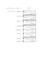
トラック内において1つのデータ単位となるセクターの構造は図17に示される。
図17(a)はセクターの基本構成を示す。
1セクターはパックヘッダとパックデータから成る2324バイトのパックにより形成される。
セクターの先頭には、12バイトのパックヘッダが設けられ、残りの2312バイトが1パケットとされる。
パックヘッダには、まず4バイトのパックスタートコードが配され、続いて5バイトのシステムクロックレファレンス(SCR)が設けられ、最後に3バイトのMUXレートが設けられる。
3. Sector structure
FIG. 17 shows the structure of a sector which is one data unit in a track.
FIG. 17A shows the basic structure of the sector.
One sector is formed by a pack of 2324 bytes comprising a pack header and pack data.
A 12-byte pack header is provided at the head of the sector, and the remaining 2312 bytes are set as one packet.
The pack header is provided with a 4-byte pack start code, followed by a 5-byte system clock reference (SCR), and finally a 3-byte MUX rate.
システムクロックレファレンス(SCR)は、一種の絶対時間を意味するコードであり、このSCRを基準として後述するPTS(Presentation Time Stamp :画像出力開始時刻) が決められる。
このSCRは、SCR(i) =C+i*1200、とされる。iは映像データストリーム内でのセクターのインデックスナンバーであり、これは先頭のフロントマージン部分では『0』とされている。Cは定数で常に『0』である。また1200は75Hzセクターで90KHz のシステムクロック時の値(90000/75=1200)である。
なお、このパックヘッダは映像データの全てのセクターVにおいて設けられるものである。
The system clock reference (SCR) is a code meaning a kind of absolute time, and a PTS (Presentation Time Stamp: image output start time) to be described later is determined based on the SCR.
This SCR is SCR (i) = C + i * 1200. i is the index number of the sector in the video data stream, and is set to “0” in the front front margin portion. C is a constant and is always “0”. 1200 is the value when the system clock is 90 KHz in the 75 Hz sector (90000/75 = 1200).
This pack header is provided in all sectors V of the video data.
1パックで構成されるセクターにはこのようなパックヘッダが設けられるが、セクターがビデオデータを記録するセクターとされる場合はパックヘッダに続く2312バイトのパケットは、一例として図17(b)のように構成される。
まずパックヘッダに続く18バイトにパケットヘッダが設けられる。
パケットヘッダの先頭の3バイトはパケットスタートコードとされる。そして1バイトのID、2バイトのパケット長、2バイトのSTD(system target decorder)、5バイトのPTS、5バイトのDTS(decoding time stamp) が記録される。画像出力開始時刻であるPTSは、音声データと同期をとるようにセットされる。またDTSはデコード開始時刻を示すものである。
Such a pack header is provided in a sector constituted by one pack. When the sector is a sector for recording video data, a 2312-byte packet following the pack header is shown in FIG. 17B as an example. Configured as follows.
First, a packet header is provided in 18 bytes following the pack header.
The first 3 bytes of the packet header are used as a packet start code. A 1-byte ID, a 2-byte packet length, a 2-byte STD (system target decorder), a 5-byte PTS, and a 5-byte DTS (decoding time stamp) are recorded. The PTS that is the image output start time is set so as to be synchronized with the audio data. DTS indicates a decoding start time.
このパケットヘッダに続く2294バイトがビデオパケットとされ、実際のビデオデータが記録される。つまり上述したようにIピクチャー、Pピクチャー、Bピクチャーによる映像データストリームが記録される。
なお、ビデオセクターが連続している区間において最初のビデオセクターでは、ビデオパケットはこのように2294バイトとされるが、以降の連続するビデオセクターではパケットヘッダにおけるSTDを省略でき、ビデオパケットは2296バイトに拡張される。
The 2294 bytes following the packet header are used as a video packet, and actual video data is recorded. That is, as described above, a video data stream based on an I picture, P picture, and B picture is recorded.
In the first video sector in the section where the video sectors are continuous, the video packet is thus 2294 bytes, but in subsequent video sectors, STD in the packet header can be omitted, and the video packet is 2296 bytes. To be expanded.
セクターがオーディオデータを記録するセクターとされる場合は、パックヘッダに続く2312バイトのパケットは、一例として図17(c)のように構成される。
まずビデオセクターと同様にパックヘッダに続いてパケットヘッダが設けられるが、このパケットヘッダは3バイトのパケットスタートコード、1バイトのI
D、2バイトのパケット長、2バイトのSTD、5バイトのPTSの13バイトで構成される。
そしてオーディオパケットとして2279バイトを割り当てて圧縮されたデジタルオーディオデータが記録されるようにしている。このオーディオパケットの後ろに20バイトの空きエリアを付加して2324バイトの1パック(1セクター)が構成される。
When the sector is a sector for recording audio data, a packet of 2312 bytes following the pack header is configured as shown in FIG. 17C as an example.
First, as with the video sector, a packet header is provided following the pack header. This packet header includes a 3-byte packet start code, 1-byte I
D, 2 bytes of packet length, 2 bytes of STD, 5 bytes of PTS, 13 bytes.
Digital audio data compressed by allocating 2279 bytes as audio packets is recorded. A 20-byte free area is added to the end of the audio packet to form one pack (one sector) of 2324 bytes.
セクターはこのように構成されており、このなかで同期のための時間情報はSCR,DTS,PTSとなる。つまり、1つのトラックには図16(b)のようにビデオセクターVとオーディオセクターAが時系列的に並ぶために、この同期をとることが必要であるが、この同期処理のためにSCR,DTS,PTSが用いられる。
即ち、SCRを基準クロックとして、各セクターでDTSにおいてビデオパケット又はオーディオパケットのデコードを開始する時刻が示される。さらに、PTSで出力(表示又は音声出力)を行なう時刻が示される。
このようにビデオセクターとオーディオセクターは、これらの時間情報により互いに同期がとれるように構成されている。
The sector is configured as described above, and time information for synchronization is SCR, DTS, and PTS. That is, since the video sector V and the audio sector A are arranged in time series in one track as shown in FIG. 16 (b), it is necessary to establish this synchronization. DTS and PTS are used.
That is, the time at which decoding of a video packet or an audio packet is started in the DTS in each sector using the SCR as a reference clock is indicated. Furthermore, the time at which the output (display or audio output) is performed with the PTS is indicated.
As described above, the video sector and the audio sector are configured to be synchronized with each other based on the time information.
3.ディスク上の配置
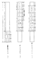
CD−DA及びビデオCDのディスク上の構造を図18に示した。
CD−DAでは図18(a)のようにディスク最内周側にリードインエリアが設けられ、ここにTOCデータが記録されている。TOCデータとしては、各トラックの開始位置やトラック数、演奏時間等が記録されている。
リードインエリアに続いてトラックデータがトラック#1〜トラック#nとして記録され、最外周位置にリードアウトエリアが設けられている。各トラックには44.1KHz サンプリングで16ビット量子化のデジタルオーディオデータがサブコードデータとともに記録される。
3. Placement on disk
The structure of the CD-DA and video CD on the disk is shown in FIG.
In the CD-DA, as shown in FIG. 18A, a lead-in area is provided on the innermost circumference side of the disc, and TOC data is recorded here. As the TOC data, the start position of each track, the number of tracks, the performance time, and the like are recorded.
Following the lead-in area, track data is recorded as
一方、ビデオCDのディスク上の構造は図18(b)に示される。
ビデオCDの場合も、CD−DAとほぼ同様に、ディスク最内周側にリードインエリアが設けられ、TOCデータが記録されている。そしてリードインエリアに続いてトラック#1〜トラック#nが記録され、最外周位置にリードアウトエリアが設けられている。
On the other hand, the structure of the video CD on the disc is shown in FIG.
In the case of a video CD, a lead-in area is provided on the innermost circumference side of the disc, and TOC data is recorded, as in CD-DA.
ただしビデオCDの場合、トラック#1は第1トラックとしての実際の映像又は音声データの記録には用いられておらず、ビデオCDデータトラックとして使用されている。
そして、トラック#2〜トラック#nに実際の映像/音声データが記録される。即ちトラック#2〜トラック#nは図17で説明したようなビデオセクター及びオーディオセクターによって図16のように構成されている。
また、ビデオCDの場合、オーディオデータのみが記録されたトラックを設けることもでき、その場合はCD−DAと同様の44.1KHz サンプリングで16ビット量子化のデジタルオーディオデータが記録される。
However, in the case of a video CD,
The actual video / audio data is recorded on
In the case of a video CD, a track on which only audio data is recorded can be provided. In that case, 16-bit quantized digital audio data is recorded with the same 44.1 KHz sampling as in the CD-DA.
なお、CD−DA、ビデオCDのいづれも、トラック数は最大99まで可能となる。従ってCD−DAの場合、最大99曲、ビデオCDの場合最大98シーケンスが記録できる。シーケンスとは動画の連続した1つの区切りのことであり、例えばカラオケなどの画像が記録されていた場合、1曲(1トラック)が1シーケンスであり、また映画の場合は通常1ディスクが1シーケンスとなる。 Note that the maximum number of tracks is 99 for both CD-DA and video CD. Therefore, a maximum of 99 songs can be recorded in the case of CD-DA, and a maximum of 98 sequences can be recorded in the case of a video CD. A sequence is a continuous segment of a moving image. For example, when an image such as karaoke is recorded, one song (one track) is one sequence. In the case of a movie, one disc is usually one sequence. It becomes.
トラック#1を用いたビデオCDデータトラックには、図18(b)下段に示すようにPVD(基本ボリューム記述子)、カラオケベーシックインフォメーションエリア、ビデオCDインフォメーションエリア、セグメントプレイアイテムエリア、その他のファイル(CD−Iアプリケーションプログラム等)が用意されている。これらについては後述する。
As shown in the lower part of FIG. 18B, the video CD data track using the
5.TOC及びサブコード
ビデオCD及びCD−DAにおいてリードインエリアに記録されるTOC及びサブコードについて説明する。
ビデオCD及びCD−DAにおいて記録されるデータの最小単位は1フレームとなる。98フレームで1ブロックが構成される。
5). TOC and subcode
The TOC and subcode recorded in the lead-in area in the video CD and CD-DA will be described.
The minimum unit of data recorded in the video CD and CD-DA is one frame. One block is composed of 98 frames.
1フレームの構造は図20のようになる。
1フレームは588ビットで構成され、先頭24ビットが同期データ、続く14ビットがサブコードデータエリアとされる。そして、その後にデータ及びパリティが配される。
The structure of one frame is as shown in FIG.
One frame is composed of 588 bits, with the first 24 bits being the synchronization data and the subsequent 14 bits being the subcode data area. After that, data and parity are arranged.
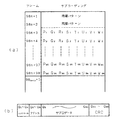
この構成のフレームが98フレームで1ブロックが構成され、98個のフレームから取り出されたサブコードデータが集められて図21(a)のような1ブロックのサブコードデータが形成される。
98フレームの先頭の第1、第2のフレーム(フレーム98n+1,フレーム98n+2)からのサブコードデータは同期パターンとされている。そして、第3フレームから第98フレーム(フレーム98n+3〜フレーム98n+98)までで、各96ビットのチャンネルデータ、即ちP,Q,R,S,T,U,V,Wのサブコードデータが形成される。
The frame having this configuration is composed of 98 frames to form one block, and the subcode data extracted from the 98 frames is collected to form one block of subcode data as shown in FIG.
The subcode data from the first and second frames (
このうち、アクセス等の管理のためにはPチャンネルとQチャンネルが用いられる。ただし、Pチャンネルはトラックとトラックの間のポーズ部分を示しているのみで、より細かい制御はQチャンネル(Q1 〜Q96)によって行なわれる。96ビットのQチャンネルデータは図21(b)のように構成される。 Of these, the P channel and the Q channel are used for access management. However, the P channel only shows a pause portion between tracks, and finer control is performed by the Q channel (Q 1 to Q 96 ). The 96-bit Q channel data is configured as shown in FIG.
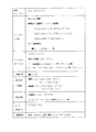
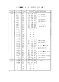
まずQ1 〜Q4 の4ビットはコントロールデータとされ、オーディオのチャンネル数、エンファシス、CD−ROMの識別などに用いられる。
即ち、4ビットのコントロールデータは次のように定義される。
『0***』・・・・2チャンネルオーディオ
『1***』・・・・4チャンネルオーディオ
『*0**』・・・・CD−DA
『*1**』・・・・CD−ROM
『**0*』・・・・デジタルコピー不可
『**1*』・・・・デジタルコピー可
『***0』・・・・プリエンファシスなし
『***1』・・・・プリエンファシスあり
First, 4 bits of Q 1 to Q 4 are used as control data and used for the number of audio channels, emphasis, CD-ROM identification, and the like.
That is, 4-bit control data is defined as follows.
"0 ***" ... 2 channel audio "1 ***" ... 4 channel audio "* 0 ***" ... CD-DA
"* 1 **" ... CD-ROM
"*** 0 *" ... Digital copy not possible "** 1 *" ... Digital copy allowed "*** 0" ... No pre-emphasis "*** 1" ... Pre With emphasis
次にQ5 〜Q8 の4ビットはアドレスとされ、これはサブQデータのコントロールビットとされている。
このアドレス4ビットが『0001』である場合は、続くQ9 〜Q80のサブQデータはオーディオQデータであることを示し、また『0100』である場合は、続くQ9 〜Q80のサブQデータがビデオQデータであることを示している。
そしてQ9 〜Q80で72ビットのサブQデータとされ、残りのQ81〜Q96はCRCとされる。
Next 4 bits of Q 5 to Q 8 are an address, which is the control bit in the sub-Q data.
If this
Q 9 to Q 80 are 72-bit sub-Q data, and the remaining Q 81 to Q 96 are CRC.
リードインエリアにおいては、そこに記録されているサブQデータが即ちTOC情報となる。
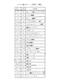
つまりリードインエリアから読み込まれたQチャンネルデータにおけるQ9 〜Q80の72ビットのサブQデータは、図22(a)のような情報を有するものである。サブQデータは各8ビットのデータを有している。
In the lead-in area, the sub-Q data recorded there is TOC information.
In other words, the 72-bit sub Q data of Q 9 to Q 80 in the Q channel data read from the lead-in area has information as shown in FIG. The sub-Q data has 8-bit data.
まずトラックナンバが記録される。リードインエリアではトラックナンバは『00』に固定される。
続いてPOINT(ポイント)が記され、さらにトラック内の経過時間としてMIN(分)、SEC(秒)、FRAME(フレーム番号)が示される。
さらに、PMIN,PSEC,PFRAMEが記録されるが、このPMIN,PSEC,PFRAMEは、POINTの値によって意味が決定されている。
First, the track number is recorded. In the lead-in area, the track number is fixed to “00”.
Subsequently, POINT (point) is described, and further, MIN (minute), SEC (second), and FRAME (frame number) are indicated as the elapsed time in the track.
Further, PMIN, PSEC, and PFRAME are recorded. The meaning of PMIN, PSEC, and PFRAME is determined by the value of POINT.
POINTの値が『01』〜『99』のときは、その値はトラックナンバを意味し、この場合PMIN,PSEC,PFRAMEにおいては、そのトラックナンバのトラックのスタートポイント(絶対時間アドレス)が分(PMIN),秒(PSEC),フレーム番号(PFRAME)として記録されている。 When the value of POINT is "01" to "99", the value means a track number. In this case, in PMIN, PSEC, and PFRAME, the start point (absolute time address) of the track number is a minute ( PMIN), second (PSEC), and frame number (PFRAME).
POINTの値が『A0』のときは、PMINに最初のトラックのトラックナンバが記録される。また、PSECの値によってCD−DA,CD−I,CD−ROM(XA仕様)の区別がなされる。
POINTの値が『A1』のときは、PMINに最後のトラックのトラックナンバが記録される。
POINTの値が『A2』のときは、PMIN,PSEC,PFRAMEにリードアウトエリアのスタートポイントが絶対時間アドレスとして示される。
When the value of POINT is “A0”, the track number of the first track is recorded in PMIN. Further, CD-DA, CD-I, and CD-ROM (XA specification) are distinguished by the value of PSEC.
When the value of POINT is “A1”, the track number of the last track is recorded in PMIN.
When the value of POINT is “A2”, the start point of the lead-out area is indicated as an absolute time address in PMIN, PSEC, and PFRAME.
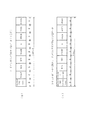
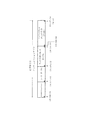
例えば6トラックが記録されたディスクの場合、このようなサブQデータによるTOCとしては図23のようにデータが記録されていることになる。
図23に示すようにトラックナンバTNOは全て『00』である。
ブロックNO.とは上記のように98フレームによるブロックデータとして読み込まれた1単位のサブQデータのナンバを示している。
各TOCデータはそれぞれ3ブロックにわたって同一内容が書かれている。
図示するようにPOINTが『01』〜『06』の場合、PMIN,PSEC,PFRAMEとしてトラック#1〜トラック#6のスタートポイントが示されている。
For example, in the case of a disc on which 6 tracks are recorded, data is recorded as such TOC by sub-Q data as shown in FIG.
As shown in FIG. 23, the track numbers TNO are all “00”.
Block NO. Indicates the number of one unit of sub-Q data read as block data of 98 frames as described above.
Each TOC data has the same contents written over three blocks.
As shown in the figure, when POINT is “01” to “06”, the start points of
そしてPOINTが『A0』の場合、PMINに最初のトラックナンバとして『01』が示される。またPSECの値によってディスクが識別され、このディスクがCD−ROM(XA仕様)の場合は、図示するようにPSEC=『20』とされる。CD−DAの場合は『00』、CD−Iの場合は『10』となる。 When POINT is “A0”, “01” is indicated as the first track number in PMIN. Further, when the disk is identified by the value of PSEC and this disk is a CD-ROM (XA specification), PSEC = “20” as shown in the figure. “00” for CD-DA and “10” for CD-I.
そしてPOINTの値が『A1』の位置にPMINに最後のトラックのトラックナンバが記録され、POINTの値が『A2』の位置に、PMIN,PSEC,PFRAMEにリードアウトエリアのスタートポイントが示される。
ブロックn+27以降は、ブロックn〜n+26の内容が再び繰り返して記録されている。
Then, the track number of the last track is recorded in PMIN at the point value “A1”, and the start point of the lead-out area is indicated at PMIN, PSEC, and PFRAME at the point “A2”.
After block n + 27, the contents of blocks n to n + 26 are repeatedly recorded.
トラック#1〜#n及びリードアウトエリアにおいては、そこに記録されているサブQデータは図22(b)の情報を有する。
まずトラックナンバが記録される。即ち各トラック#1〜#nでは『01』〜『99』のいづれかの値となる。またリードアウトエリアではトラックナンバは『AA』とされる。
続いてインデックスとして各トラックをさらに細分化することができる情報が記録される。
In the
First, the track number is recorded. That is, each of the
Subsequently, information that can further subdivide each track is recorded as an index.
そして、トラック内の経過時間としてMIN(分)、SEC(秒)、FRAME(フレーム番号)が示される。
さらに、AMIN,ASEC,AFRAMEとして、絶対時間アドレスが分(AMIN),秒(ASEC),フレーム番号(AFRAME)として記録されている。
Then, MIN (minute), SEC (second), and FRAME (frame number) are indicated as the elapsed time in the track.
Further, absolute time addresses are recorded as minutes (AMIN), seconds (ASEC), and frame numbers (AFRAME) as AMIN, ASEC, and AFRAME.
6.ディレクトリ構造
ビデオCDのディレクトリ構造を図19に示す。
図18(b)に示したビデオCDにおいてはディレクトリ構造として図19のように、ビデオCDディレクトリ、MPEGオーディオ/ビデオ、CD−DA、セグメント、CD−I、カラオケ、EXTが要求される。
ビデオCDディレクトリは図18(b)のトラック#1内におけるビデオCDインフォメーションエリアに記録されるものであり、ディスクインフォメーション、エントリーテーブル、リストIDオフセットテーブル、プレイシーケンスディスクリプタが設けられる。これら各々については後述する。
6). Directory structure
FIG. 19 shows the directory structure of the video CD.
In the video CD shown in FIG. 18B, the directory structure requires a video CD directory, MPEG audio / video, CD-DA, segment, CD-I, karaoke, and EXT as shown in FIG.
The video CD directory is recorded in the video CD information area in
MPEGオーディオ/ビデオは即ちオーディオ/ビデオのシーケンスデータであり、つまり最大99トラックが記録できるビデオCDではトラック#2〜トラック#99までの最大98個のシーケンスデータとなる。
MPEG audio / video is audio / video sequence data. That is, a video CD capable of recording up to 99 tracks has a maximum of 98 sequence data from
セグメントとは最大1980単位記録できるセグメントプレイアイテム#1〜#1980であり、これはトラック#1内におけるセグメントプレイアイテムエリアに記録される。
A segment is a segment
さらに、トラック#1内におけるCD−Iアプリケーションプログラムは、そのディレクトリファイルが、CD−Iとして、ディレクトリ構造に組み込まれ、またカラオケベーシックインフォメーションエリアが使用される場合は、そのディレクトリファイルが、カラオケとして、ディレクトリ構造に組み込まれる。
オーディオデータのみが記録されたトラックを設ける場合は、そのディレクトリファイルが、CD−DAとして、ディレクトリ構造に組み込まれ、また、PSD_X.VCD及びLOT_X.VCDが使用される場合は、そのディレクトリファイルが、EXTとして、ディレクトリ構造に組み込まれる。
Further, the CD-I application program in the
When providing a track in which only audio data is recorded, the directory file is incorporated in the directory structure as CD-DA, and PSD_X. VCD and LOT_X. When VCD is used, the directory file is incorporated into the directory structure as EXT.
7.ビデオCDデータトラック
ビデオCDにおいては上述したようにトラック#1がビデオCDデータトラックとして使用される。
そして、図18を用いて上述したように、この領域にPVD(基本ボリューム記述子)、カラオケベーシックインフォメーションエリア、ビデオCDインフォメーションエリア、セグメントプレイアイテムエリア、その他のファイル(CD−Iアプリケーションプログラム等)が設けられる。
7). Video CD data track
In the video CD, as described above, the
As described above with reference to FIG. 18, PVD (basic volume descriptor), karaoke basic information area, video CD information area, segment play item area, and other files (CD-I application program, etc.) are stored in this area. Provided.
図18(b)に示したようにPVDはディスク上の絶対時間アドレス00:02:16(分/秒/フレーム)からの位置に配置される。
またカラオケベーシックインフォメーションエリアは絶対時間アドレス00:02:16からの位置に配置される。
ビデオCDインフォメーションエリアは絶対時間アドレス00:04:00からの位置に配置される。
そして、セグメントプレイアイテムエリアはビデオCDインフォメーションエリア内で示される位置から、またCD−IアプリケーションプログラムはPVD内で示される位置から、それぞれ配置される。
As shown in FIG. 18B, the PVD is arranged at a position from the absolute time address 00:02:16 (minute / second / frame) on the disk.
The karaoke basic information area is arranged at a position from the absolute time address 00:02:16.
The video CD information area is arranged at a position from the absolute time address 00:04:00.
The segment play item area is arranged from the position shown in the video CD information area, and the CD-I application program is arranged from the position shown in the PVD.
a.PVD(基本ボリューム記述子)
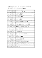
ディスク上の絶対時間アドレス00:02:16からの位置に配置されるPVD(基本ボリューム記述子)の構造は図24のとおりである。
まず、ボリューム構造スタンダードIDとして『CD001』というデータが記録される。続いてシステム認識子、ボリューム認識子、アルバムのボリューム数、アルバムセットシーケンス番号が記録される。1つのアルバムは1枚のディスクから構成される場合と複数のディスクから成る場合があるが、アルバムのボリューム数はその1つのアルバムにおけるディスクの数となる。そして、そのうちの何枚目のディスクであるかがアルバムセットシーケンス番号とされる。
a. PVD (basic volume descriptor)
The structure of the PVD (basic volume descriptor) arranged at the position from the absolute time address 00:02:16 on the disk is as shown in FIG.
First, data “CD001” is recorded as a volume structure standard ID. Subsequently, a system identifier, a volume identifier, the number of album volumes, and an album set sequence number are recorded. One album may be composed of one disc or a plurality of discs, and the number of volumes of the album is the number of discs in the one album. The number of discs among them is the album set sequence number.
そして論理ブロックサイズ、パステーブル、パステーブルのアドレス、ルートディレクトリレコードが記録される。
また、アルバム認識子としてディスクタイトルが記録され、続いて発行者、著者名が記録される。
さらにアプリケーション認識子としてCD−Iのアプリケーションネームが記録される。
続いてコピーライトファイル名、要約ファイル名、目録ファイル名、製作日時、修正日時、満期日時、有効日時、ファイル構造スタンダードバージョン番号、最後にXAラベルコードが記録される。
The logical block size, path table, path table address, and root directory record are recorded.
Also, a disc title is recorded as an album recognizer, followed by an issuer and author name.
Further, an application name of CD-I is recorded as an application identifier.
Subsequently, the copyright file name, summary file name, catalog file name, production date / time, modification date / time, expiration date / time, valid date / time, file structure standard version number, and finally the XA label code are recorded.
b.ビデオCDインフォメーション
ディスク上の絶対時間アドレス00:04:00からは、ビデオCDインフォメーションが記録される。
このビデオCDインフォメーションとしては、図25のようにディスクインフォメーション、エントリーテーブル、リストIDオフセットテーブル、プレイシーケンスディスクリプタ(PSD)が設けられる。これらが図19に示したビデオCDディレクトリにおける各ファイル構成となる。
b. Video CD information
Video CD information is recorded from the absolute time address 00:04:00 on the disc.
As the video CD information, disc information, an entry table, a list ID offset table, and a play sequence descriptor (PSD) are provided as shown in FIG. These are the file structures in the video CD directory shown in FIG.
ディスクインフォメーションはビデオCDインフォメーションの先頭位置である絶対時間アドレス00:04:00から配置されている。
エントリーテーブルは絶対時間アドレス00:04:01から配置される。
リストIDオフセットテーブルは絶対時間アドレス00:04:02から絶対時間アドレス00:04:33までの位置に配置される。
プレイシーケンスディスクリプタ(PSD)は絶対時間アドレス00:04:34から配置され、最大で絶対時間アドレス00:07:64までとなる。
The disc information is arranged from the absolute time address 00:04:00 which is the head position of the video CD information.
The entry table is arranged from the absolute time address 00:04:01.
The list ID offset table is arranged at a position from the absolute time address 00:04:02 to the absolute time address 00:04:33.
The play sequence descriptor (PSD) is arranged from the absolute time address 00:04:34, and the maximum is the absolute time address 00:07:64.
−b1− ディスクインフォメーション
まず絶対時間アドレス00:04:00から配置されるディスクインフォメーションについて説明する。
ディスクインフォメーションの領域は図26のような構造とされる。
-B1- Disc information
First, disc information arranged from the absolute time address 00:04:00 will be described.
The disc information area is structured as shown in FIG.
まず、第1〜8バイト目にビデオCDのシステム認識子が記録される。
続いて第9〜10バイト目の2バイトでバージョン番号が記録される。バージョン2.0 の場合『$0200』となる。
続いて第11〜26バイト目の16バイトで各ディスクに固有に与えられているアルバム認識子が記録される。
First, the system identifier of the video CD is recorded in the first to eighth bytes.
Subsequently, the version number is recorded in 2 bytes of the 9th to 10th bytes. In the case of version 2.0, it will be “$ 0200”.
Subsequently, an album identifier uniquely assigned to each disc is recorded in 16 bytes of 11th to 26th bytes.
第27〜28バイト目の2バイトにアルバムでのボリューム数、続く2バイトにアルバムセットシーケンス番号が記録される。1つのアルバムは1枚のディスクから構成される場合と複数のディスクから成る場合があるが、アルバムのボリューム数はその1つのアルバムにおけるディスクの数となる。そして、そのうちの何枚目のディスクであるかがアルバムセットシーケンス番号とされる。 The number of volumes in the album is recorded in the 2nd byte of the 27th to 28th bytes, and the album set sequence number is recorded in the subsequent 2 bytes. One album may be composed of one disc or a plurality of discs, and the number of volumes of the album is the number of discs in the one album. The number of discs among them is the album set sequence number.
第31〜43バイト目の13バイトに、動画トラックのサイズマップが記録される。これは、各トラック#2〜#99についてのデータがNTSC信号であるかPAL信号であるかを判別するデータである。即ち13バイトのうちの最初のバイトのLSBはトラック#2を示し、ここから最後のバイトのビット1までで、各1ビットでトラック#99までのデータが記録される。各トラックに対応するビットについて『0』であればNTSCを、また『1』であればPALを示すことになる。
The size map of the moving image track is recorded in 13 bytes from the 31st to 43rd bytes. This is data for determining whether the data for
第44バイト目に1バイトでステータスフラグが記録される。この1バイトではビット0〜ビット7のうち、ビット0がカラオケベーシックインフォメーションのフラグとされる。
ビット0が『0』であればカラオケベーシックインフォメーションは存在せず、また『1』であれば絶対時間アドレス00:03:00のセクターからカラオケベーシックインフォメーションが記録されていることが示される。
A status flag is recorded in 1 byte at the 44th byte. In this 1 byte,
If
第45〜48バイト目の4バイトに、PSD(プレイシーケンスディスクリプタ)のバイトサイズが示される。図25のようにPSDは絶対時間アドレス00:04:34から、最大で絶対時間アドレス00:07:64までに記録され、バイトサイズは可変長であるためバイトサイズがここで示される。 The 4th byte of the 45th to 48th bytes indicates the byte size of the PSD (play sequence descriptor). As shown in FIG. 25, the PSD is recorded from the absolute time address 00:04:34 to the absolute time address 00:07:64 at the maximum. Since the byte size is variable, the byte size is indicated here.
後述するがPSDとは、プレイバックコントロールに用いる複数のリスト(セレクションリスト、プレイリスト、エンドリスト)として構成されるものであり、各リストがPSDとして記録されている。なお、PSDが存在しないとき、つまりプレイバックコントロール機能が付加されてないディスクの場合はこの4バイトは『0』とされる。 As will be described later, PSD is configured as a plurality of lists (selection list, play list, end list) used for playback control, and each list is recorded as PSD. When no PSD exists, that is, in the case of a disc to which no playback control function is added, these 4 bytes are set to “0”.
第49〜51バイト目の3バイトに、ファーストセグメントアドレスが示される。図18(b)に示したようにセグメントプレイアイテムエリアのスタートポイントはビデオCDインフォメーションエリアに記録されると述べたが、この3バイトがそれに相当する。 The first segment address is shown in 3 bytes of the 49th to 51st bytes. As shown in FIG. 18B, it has been described that the start point of the segment play item area is recorded in the video CD information area, and these 3 bytes correspond to it.
セグメントプレイアイテムについては後述するが、最大1980個のセグメントプレイアイテムを図18に示したセグメントプレイアイテムエリアに記録することができる。それぞれのセグメントプレイアイテムとしてはプレイバックコントロールなどに用いられる映像データや音声データが記録される。 Although the segment play item will be described later, a maximum of 1980 segment play items can be recorded in the segment play item area shown in FIG. As each segment play item, video data and audio data used for playback control and the like are recorded.
第52バイト目の1バイトに、オフセット乗数が記録される。これはPSD内における各リストのアドレス算出に用いる乗数であり、この場合『8』に固定されている。 An offset multiplier is recorded in one byte of the 52nd byte. This is a multiplier used to calculate the address of each list in the PSD, and in this case, is fixed to “8”.
第53〜54バイト目の2バイトにリストIDの数が示される。これは後述するリストIDオフセットテーブルに記録されている有効なリストIDの数を示すものとなる。 The number of list IDs is indicated in 2 bytes of the 53rd to 54th bytes. This indicates the number of valid list IDs recorded in a list ID offset table described later.
第55〜56バイト目の2バイトに、セグメントプレイアイテムエリアに記録されているセグメントプレイアイテムの数が示される。 The number of segment play items recorded in the segment play item area is indicated in 2 bytes of the 55th to 56th bytes.
第57〜2036バイト目の1980バイトに、セグメントプレイアイテムコンテンツテーブルが記録される。これはセグメントプレイアイテムエリアに記録されている各セグメントプレイアイテムの属性を示すものである。
即ちセグメントプレイアイテムは#1〜#1980として最大1980個を記録することができるが、セグメントプレイアイテムコンテンツテーブルは図27のように各セグメントプレイアイテム#1〜#1980について1バイトづつ対応して、それぞれの属性データが記録されている。
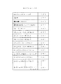
1バイトの各ビット(ビット0〜ビット7)について属性データは次のように定義されている。ただしビット6,ビット7は未定義である。
The segment play item content table is recorded in 1980 bytes of the 57th to 2036th bytes. This indicates the attribute of each segment play item recorded in the segment play item area.
In other words, segment play items can record a maximum of 1980 as # 1 to # 1980, but the segment play item content table corresponds to each segment
The attribute data is defined as follows for each bit of 1 byte (
ビット1,ビット0
『00』・・・・MPEGオーディオデータがない
『01』・・・・モノラルオーディオデータ
『10』・・・・ステレオオーディオデータ
『11』・・・・デュアルチャンネルオーディオデータ
ビット4〜ビット2
『000』・・・・MPEGビデオデータがない
『001』・・・・NTSCサイズの標準レベル静止画データ
『010』・・・・NTSCサイズの高精細レベル静止画データ
『011』・・・・NTSCサイズの動画データ
『100』・・・・未使用
『101』・・・・PALサイズの標準レベル静止画データ
『110』・・・・PALサイズの標準及び高精細レベル静止画データ
『111』・・・・PALサイズの動画データ
ビット5
『0』・・・・単独アイテム、又は連続アイテムの先頭アイテム
『1』・・・・連続アイテムのうちの第2以降のアイテム
“00”: No MPEG audio data “01”: Mono audio data “10”: Stereo audio data “11”: Dual channel
"000" ... No MPEG video data "001" ... NTSC standard level still image data "010" ... NTSC high definition level still image data "011" ... NTSC size video data "100" ... unused "101" ... PAL size standard level still image data "110" ... PAL size standard and high definition level still image data "111" .... PAL size
“0”: Single item or top item of continuous item “1”: Second item or later of continuous items
このようなセグメントプレイアイテムコンテンツテーブルに続く、ディスクインフォメーションの第2037〜2048バイト目までは未定義とされている。 The 2037th to 2048th bytes of the disc information following the segment play item content table are undefined.
−b2− エントリーテーブル
図25のようにビデオCDインフォメーションエリアにおいて、絶対時間アドレス00:04:01からはエントリーテーブルが配置される。
このエントリーテーブルにおいて、オーディオ/ビデオシーケンス内の所定のポイントをスタートポイントとしてエントリーしておくことができる。
従って、このエントリーテーブルには、エントリーファイルであることのID、バージョン番号、エントリー数等が記録され、実際のエントリーポイントとして最大500個のエントリーが記録される。つまりエントリー#0〜エントリー#499までを設定できる。
1つのエントリーは4バイトで構成され、そのうちの1バイトでトラックナンバが示され、残りの3バイトでセクターアドレス、即ちASEC,AMIN,AFRAMEが示される。
-B2- Entry table
In the video CD information area as shown in FIG. 25, an entry table is arranged from the absolute time address 00:04:01.
In this entry table, a predetermined point in the audio / video sequence can be entered as a start point.
Therefore, an ID indicating that the file is an entry file, a version number, the number of entries, and the like are recorded in this entry table, and a maximum of 500 entries are recorded as actual entry points. That is,
One entry is composed of 4 bytes, of which 1 byte indicates a track number, and the remaining 3 bytes indicate a sector address, that is, ASEC, AMIN, and AFRAME.
−b3− リストIDオフセットテーブル
ビデオCDインフォメーションエリアの絶対時間アドレス00:04:02から00:04:33までのセクターにはリストIDオフセットテーブルが配される。
-B3- List ID offset table
A list ID offset table is arranged in the sector from the absolute time address 00:04:02 to 00:04:33 in the video CD information area.
後述するPSDに記録されるプレイリストやセレクションリストは、それぞれ固有にリストIDが付されている。このリストIDオフセットテーブルにはPSDにおける各リストの位置を示すオフセット量が示されている。そしてユーザーが再生させたい所望のリストを指定したときは、このビデオCD再生装置はリストIDオフセットテーブルを参照することで、指定されたリストのPSD内における位置を把握し、リスト内容を実行させることができる。 Each playlist and selection list recorded in the PSD, which will be described later, has a unique list ID. This list ID offset table shows an offset amount indicating the position of each list in the PSD. When the user specifies a desired list to be played back, the video CD playback device refers to the list ID offset table to grasp the position of the specified list in the PSD and execute the list contents. Can do.
リストIDオフセットテーブルは図28のように最大32セクターで構成され、各2バイトづつでオフセット量が示されており、64Kのオフセットが表現される。
後述するPSDのエリアは、絶対時間アドレス00:04:34から最大で絶対時間アドレス00:07:64までとされ、つまり最大で3秒31フレームのエリアとなる。これは256セクターに相当する。256セクターは512Kバイトである。
The list ID offset table is composed of a maximum of 32 sectors as shown in FIG. 28. The offset amount is indicated by 2 bytes each, and a 64K offset is expressed.
The PSD area to be described later is an absolute time address 00:04:34 up to an absolute time address 00:07:64, that is, an area of 3 frames and 31 frames at the maximum. This corresponds to 256 sectors. 256 sectors are 512K bytes.
リストIDオフセットテーブルで表現される64Kのオフセットに8を乗じた数は512Kバイトとなる。『8』とは上記図26のディスクインフォメーションの第52バイト目のオフセット乗数である。
つまり、オフセットとは、1オフセットが8バイトに相当し、従ってオフセット値にオフセット乗数『8』を乗じることによってPSDエリアにおける所定の位置を、PSD先頭位置(オフセット『0000』の位置)からのバイトポジションとして示す数値となる。
The number obtained by multiplying the 64K offset represented by the list ID offset table by 8 is 512K bytes. “8” is the offset multiplier of the 52nd byte of the disk information of FIG.
In other words, an offset corresponds to 8 bytes per offset. Therefore, by multiplying the offset value by the offset multiplier “8”, a predetermined position in the PSD area is changed from the PSD head position (offset “0000” position) to the byte. It is a numerical value shown as a position.
まずスタートアップオフセットが記録される。これは『$0000』の値に固定されている。
この図28はリストIDの数が6個の場合であり、リストID1〜リストID6についてそれぞれオフセット値が示される。
なお、必ずPSDの先頭に配されるリストID1については、オフセット値は『$0000』の値に固定されている。
また、未使用のリストIDについてはオフセット値は『$FFFF』とされる。
First, the startup offset is recorded. This is fixed at a value of “$ 0000”.
FIG. 28 shows a case where the number of list IDs is six, and offset values are shown for list ID1 to list ID6.
Note that the offset value is always fixed to the value of “$ 0000” for the
For the unused list ID, the offset value is “$ FFFF”.
−b4− PSD(プレイシーケンスディスクリプタ)
絶対時間アドレス00:04:34からPSDが設けられる。
このPSDにはプレイリスト、セレクションリスト、エンドリストが記録されている。これらのリストは後述するプレイバックコントロールに用いられるもので再生内容や階層分岐を示すデータが記録されている。
プレイリストは下階層への分岐のためのデータ(選択メニュー)含まず、一連の再生すべき内容を指定しているリストである。
一方、セレクションリストは下階層への分岐のためのデータ(選択メニュー)を含むリストである。
-B4- PSD (play sequence descriptor)
PSD is provided from absolute time address 00:04:34.
In this PSD, a play list, a selection list, and an end list are recorded. These lists are used for playback control, which will be described later, in which data indicating playback contents and hierarchical branches are recorded.
The playlist does not include data (selection menu) for branching to a lower hierarchy, and is a list that specifies a series of contents to be reproduced.
On the other hand, the selection list is a list including data (selection menu) for branching to a lower hierarchy.
なお、最初に再生されるべきリスト(プレイリスト又はセレクションリスト)はリストID1とされ、PSDの先頭位置(オフセット『0000』の位置)に記録される。
The list to be reproduced first (play list or selection list) is set as
* プレイリスト
一連の再生すべき内容を指定しているプレイリストは、図29のように構成されている。
まず、1バイトのプレイリストヘッダが設けられ、プレイリストであることが示される。
続いてナンバオブアイテムとして、このプレイリストに記録されているプレイアイテムの数が示される。プレイアイテムとは再生すべき内容を示すデータであり、プレイアイテム#1ナンバ〜#Nナンバとしてそのプレイアイテムを指定するデータがプレイリストに記録される。
ナンバオフアイテムに続いて2バイトで、各リストに固有のリストIDが記録される。
* playlist
A play list designating a series of contents to be reproduced is configured as shown in FIG.
First, a 1-byte playlist header is provided to indicate that the playlist is a playlist.
Subsequently, the number of play items recorded in the play list is shown as the number of items. The play item is data indicating contents to be reproduced, and data specifying the play item as the
Following the number-off item, a list ID unique to each list is recorded in 2 bytes.
続いて2バイトづつ、プリビアスリストオフセット、ネクストリストオフセット、リターンリストオフセットが記録される。
プリビアスリストオフセットは、プリビアス操作がなされた場合に進むべきリストの位置(オフセット)を示しているものである。例えばリストが階層化される場合などで、プリビアスリストオフセットで1段上位のリストの位置が指定されていれば、ユーザーは、プリビアス操作で前のリストによる動作状態に戻すことができる。
プリビアスリストオフセットが『$FFFF』であるときは、プリビアス動作は禁じられる。
Subsequently, the previous list offset, the next list offset, and the return list offset are recorded in units of 2 bytes.
The previous list offset indicates the position (offset) of the list to be advanced when the previous operation is performed. For example, when the list is hierarchized, if the position of the list one level higher is specified by the previous list offset, the user can return to the operation state of the previous list by the previous operation.
When the previous list offset is “$ FFFF”, the previous operation is prohibited.
ネクストリストオフセットは、当該プレイリストによって指定された再生動作が終了した際、又はネクスト操作がなされた際に、連続して進むべきリストの位置を示している。ネクストリストオフセットが『$FFFF』であることは禁止されている。 The next list offset indicates the position of the list that should be continuously advanced when the reproduction operation designated by the play list is completed or when the next operation is performed. It is prohibited that the next list offset is “$ FFFF”.
リターンリストオフセットはリターン操作がなされた場合に進むべきリストの位置を示しているものである。例えばリストが階層化される場合などにおいて、リターンリストオフセットで最上位のリストの位置が指定されていれば、ユーザーはリターン操作で最上位のリストによる動作状態まで戻すことができる。 The return list offset indicates the position of the list to be advanced when a return operation is performed. For example, when the list is hierarchized, if the position of the highest list is specified by the return list offset, the user can return to the operation state by the highest list by the return operation.
続いて、2バイトのプレイングタイム、1バイトのプレイアイテムウエイトタイム、1バイトのオートポーズウエイトタイムが記録される。
プレイングタイムはこのプレイリストに基づく再生動作のセクター数を示す。
Subsequently, a 2-byte playing time, a 1-byte play item wait time, and a 1-byte auto pause wait time are recorded.
The playing time indicates the number of sectors of the reproduction operation based on this playlist.
プレイアイテムウエイトタイムは各プレイアイテムの再生終了時の待機時間を示している。『$00』〜『$FE』までで待機時間0〜2000秒が示される。『$FF』の場合は、ユーザーの操作を待つものとされる。
オートポーズウエイトタイムは、オートポーズ動作における待機時間を示している。
The play item wait time indicates a waiting time at the end of reproduction of each play item. A waiting time of 0 to 2000 seconds is indicated from “$ 00” to “$ FE”. In the case of “$ FF”, the operation of the user is waited.
The auto pause wait time indicates a standby time in the auto pause operation.
最後に、再生されるべきプレイアイテム#1〜#Nについてのナンバーが各2バイトで示される。
このプレイアイテムナンバー(PIN)は図30のように定義されている。
Finally, the numbers for
This play item number (PIN) is defined as shown in FIG.
PIN=『0』又は『1』のときは、そのプレイアイテムは何も再生しないものとされる。
PIN=『2』〜『99』のときは、そのPINはトラックナンバを示す。例えばPIN=『5』であれば、そのプレイアイテムはトラック#5を再生するプレイアイテムとなる。
When PIN = “0” or “1”, the play item is not played back.
When PIN = “2” to “99”, the PIN indicates a track number. For example, if PIN = “5”, the play item is a play item for reproducing
PIN=『100』〜『599』のときは、その(PIN−100)の値がエントリーテーブルにおけるエントリーを示す。上述したようにエントリーテーブルとしてはエントリー#0〜#499として最大500個のエントリーポイントを示すことができるが、その(PIN−100)の値として#1〜#500のいづれかのエントリーナンバーが指定される。
When PIN = “100” to “599”, the value of (PIN-100) indicates an entry in the entry table. As described above, the entry table can indicate a maximum of 500 entry points as
PIN=『1000』〜『2927』のときは、その(PIN−999)の値がセグメントプレイアイテムのナンバーを示す。セグメントプレイアイテムエリアにおいてはセグメントプレイアイテム#1〜#1980として最大1980個のセグメントプレイアイテムを記録できるが、(PIN−999)の値として#1〜#1980のいづれかのセグメントプレイアイテムが指定される。
When PIN = “1000” to “2927”, the value of (PIN−999) indicates the segment play item number. In the segment play item area, a maximum of 1980 segment play items can be recorded as segment play
PIN=『600』〜『999』及びPIN=『2980』〜『$FFFF』は未定義である。 PIN = “600” to “999” and PIN = “2980” to “$ FFFF” are undefined.
例えばプレイリストにおいて3つのプレイアイテムが記録され、プレイアイテム#1ナンバが『04』、プレイアイテム#2ナンバが『1001』、プレイアイテム#3ナンバが『102』であったとする。
すると、このプレイリストによって実行される再生動作は、まずトラック#4が再生され、続いてセグメントプレイアイテム#2が再生され、最後にエントリー#3によるエントリーポイントからの再生が行なわれることになる。
For example, it is assumed that three play items are recorded in the play list, the
Then, in the reproduction operation executed by this playlist, first, the
* セレクションリスト
セレクションリストは選択メニューを再生させてユーザーに進行すべき動作を選択させるためのリストであり、その構成は図31のようになる。
* Selection list
The selection list is a list for reproducing the selection menu and allowing the user to select an operation to proceed, and the configuration is as shown in FIG.
まず、1バイトのセレクションリストヘッダが設けられ、セレクションリストであることが示される。
続いて未使用の1バイトをおいて、1バイトでこのセレクションリストにおける選択肢数が記録される。選択肢数は最大99個である。
First, a 1-byte selection list header is provided to indicate a selection list.
Subsequently, an unused 1 byte is left, and the number of choices in this selection list is recorded in 1 byte. The maximum number of options is 99.
次に選択肢の最初のナンバーが示される。これは通常は『1』であるが、設定すべき選択肢が多く、このため複数のセレクションリストを用いる場合は、2つ目以降のセレクションリストでは、そのリストにおける最初の選択肢ナンバとなる。
続いて2バイトで、各リストに固有のリストIDが記録される。
Then the first number of choices is shown. This is normally “1”, but there are many options to be set. Therefore, when a plurality of selection lists are used, the second and subsequent selection lists are the first option numbers in the list.
Subsequently, in 2 bytes, a list ID unique to each list is recorded.
続いてプレイリストと同様に、2バイトづつ、プリビアスリストオフセット、ネクストリストオフセット、リターンリストオフセットが記録される。
つまり、プリビアスリストオフセットは、プリビアス操作がなされた場合に進むべきリストの位置(オフセット)を示し、またプリビアスリストオフセットが『$FFFF』であるときは、プリビアス動作は禁じられる。
またネクストリストオフセットは、ネクスト操作がなされた際に、連続して進むべきセレクションリストの位置を示している。連続して進むべきリストが存在しない場合は、ネクストリストオフセットは『$FFFF』とされる。
さらに、リターンリストオフセットはリターン操作がなされた場合に進むべきリストの位置を示している。
Subsequently, like the play list, the previous list offset, the next list offset, and the return list offset are recorded in units of 2 bytes.
That is, the previous list offset indicates the position (offset) of the list to be advanced when the previous operation is performed, and when the previous list offset is “$ FFFF”, the previous operation is prohibited.
The next list offset indicates the position of the selection list that should be continuously advanced when the next operation is performed. When there is no list to be continuously advanced, the next list offset is set to “$ FFFF”.
Further, the return list offset indicates the position of the list to be advanced when a return operation is performed.
例えば複数のセレクションリストで1つの選択が行なわれるように設定されている場合はこれらが効果的に用いられる。例えば、選択肢が12個設定され、3つのセレクションリストでそれぞれ各4つづつ選択肢が設定される場合は、プリビアスリストオフセットとネクストリストオフセットで各セレクションリストを前後に連続させることにより、ユーザーはプリビアス操作/ネクスト操作で所望の選択肢を探していくことができる。 For example, when one selection is made in a plurality of selection lists, these are effectively used. For example, if 12 choices are set and 4 choices are set for each of 3 selection lists, the selection list is continued by the previous list offset and the next list offset so that the user can select the previous list. A desired option can be searched by the operation / next operation.
さらにデフォルトリストオフセットが記録される。これはユーザーが選択を行なわずに実行操作を行なった場合に進むべきリストの位置を示している。
また、タイムアウトリストオフセットが記録される。これはユーザーが再生されている選択メニューに対して何等入力を行なわずに所定時間経過した場合に進むべきリストの位置を示している。タイムアウトリストオフセットが『$FFFF』である場合は、入力が行なわれずに所定時間経過した時点で、選択メニューに示された選択肢の中からランダムに特定の選択肢が選択されて、そのリストに進むことになる。
In addition, a default list offset is recorded. This indicates the position of the list to be advanced when the user performs an execution operation without making a selection.
In addition, a timeout list offset is recorded. This indicates the position of the list to be advanced when a predetermined time has passed without any input being made to the selection menu being reproduced by the user. When the timeout list offset is “$ FFFF”, when a predetermined time elapses without input, a specific option is randomly selected from the options shown in the selection menu, and the list is advanced. become.
続いて、タイムアウトまでのウエイトタイムが記録される。ユーザーによる入力がなされないまま、ここに記録されたウエイトタイムを経過するとれは上記タイムアウトリストオフセットに進むことになる。
続いてループカウント及びジャンプタイミングが示される。ループカウントは、このリストにおけるプレイアイテムの繰り返し再生回数を示す。またジャンプタイミングは、選択操作がなされた後の次のリストに進むタイミングを示す。
Subsequently, the wait time until timeout is recorded. If the wait time recorded here elapses without any user input, the process proceeds to the timeout list offset.
Subsequently, the loop count and jump timing are shown. The loop count indicates the number of times the play item in this list is repeatedly played. The jump timing indicates the timing to proceed to the next list after the selection operation is performed.
続いてプレイアイテムナンバ(PIN)が示される。これは、このセレクションリストの実行状態において再生されるべきプレイアイテムを上述した図30の定義によって示している。セレクションリストで再生されるものは、通常メニュー画面である。このためセグメントプレイアイテムとしてメニュー用のビデオデータが記録されており、各セレクションリストにおいて特定のセグメントプレイアイテムが指定される場合が多い。
例えばこのセレクションリストに対応するメニュー画像データがセグメントプレイアイテム#4として記録されている場合は、プレイアイテムナンバ(PIN)は『1003』となる。
セレクションリストにはこのように1つのPINが設けられる。
Subsequently, a play item number (PIN) is shown. This indicates the play item to be reproduced in the execution state of the selection list by the definition of FIG. 30 described above. What is played back in the selection list is usually a menu screen. For this reason, video data for a menu is recorded as a segment play item, and a specific segment play item is often specified in each selection list.
For example, when menu image data corresponding to this selection list is recorded as segment
The selection list is thus provided with one PIN.
最後に、実際に選択肢内の選択によって実行される動作を示すために各2バイトづつでセレクション#BSNオフセット〜セレクション#(BSN+NOS−1)オフセットが各2バイトで示される。なおBSNはセレクションリストの4バイト目に記録される選択肢の最初のナンバ、NOSはセレクションリストの3バイト目に記録される選択肢数である。従って選択肢1〜4を有するセレクションリストでは、セレクション#1オフセット〜セレクション#4オフセットが記録される。
Finally, selection #BSN offset to selection # (BSN + NOS-1) offset is indicated by 2 bytes each for 2 bytes each to indicate an operation actually executed by selection within the options. BSN is the first number of options recorded in the 4th byte of the selection list, and NOS is the number of options recorded in the 3rd byte of the selection list. Therefore, in the selection
この各セレクションオフセットはその選択肢が選択された場合に進むべきリスト(セレクションリスト又はプレイリスト)の位置が示される。
例えば、メニュー表示に対してユーザーが選択肢2を選択した場合は、セレクション#2オフセットに示されたリストに進むことを指定する。
Each selection offset indicates the position of a list (selection list or play list) to be advanced when the option is selected.
For example, when the user selects
* エンドリスト
エンドリストはアプリケーションの終端を示す。エンドリストの構成は8バイトとされ、1バイトがエンドリストヘッダ、7バイトが『$00』とされている。
* End list
The end list indicates the end of the application. The configuration of the end list is 8 bytes, 1 byte is the end list header, and 7 bytes are “$ 00”.
c.セグメントプレイアイテム
図18のようにビデオCDデータトラックには、セグメントプレイアイテムエリアが設けられる。セグメントプレイアイテムエリアのスタートポイントは、図26のディスクインフォメーションの第49〜51バイト目の3バイトに示される。
c. Segment play item
As shown in FIG. 18, a segment play item area is provided in the video CD data track. The start point of the segment play item area is indicated by 3 bytes of the 49th to 51st bytes of the disc information of FIG.
セグメントプレイアイテムとしては、セグメントプレイアイテムエリアにおいて最大1980個を記録することができる。
そして各セグメントプレイアイテムは、それぞれ静止画データ、動画データ、音声データなどで自由に生成することができる。
1つのセグメントは150セクターで構成される。そして各セグメントプレイアイテムは単独アイテムとして再生されるデータとしてもよいし、複数で連続的に再生されるアイテムとしてもよい。
A maximum of 1980 segment play items can be recorded in the segment play item area.
Each segment play item can be freely generated from still image data, moving image data, audio data, and the like.
One segment is composed of 150 sectors. Each segment play item may be data reproduced as a single item, or may be a plurality of items continuously reproduced.
各セグメントプレイアイテムについては図27を用いて説明したように、ディスクインフォメーションにおいて第57〜2036バイト目のセグメントプレイアイテムコンテンツテーブルによってデータ属性が示される。
このセグメントプレイアイテムを用いて上記したようにセレクションリストのメニュー画面などを用意することができる。
For each segment play item, as described with reference to FIG. 27, the data attribute is indicated by the segment play item content table of the 57th to 2036th bytes in the disc information.
Using this segment play item, the menu screen of the selection list can be prepared as described above.
[II.プレイバックコントロール(PBC)]
1 リスト構造
上述のようにプレイリスト及びセレクションリストが設けられることによって、ビデオCDではいわゆるプレイバックコントロール(PBC)を実現できる。これはビデオCDは、動画と静止画及び音声を組み合わせた簡易な対話型ソフトウエアとして実現する機能である。
[II. Playback Control (PBC)]
1 List structure
By providing the play list and the selection list as described above, so-called playback control (PBC) can be realized in the video CD. This is a function that realizes a video CD as simple interactive software combining a moving image, a still image, and sound.
すなわち、セグメントプレイアイテムエリアに、セグメントプレイアイテムとしていくつかのメニュー画面となる静止画データを用意し、セレクションリストによっていくつかの分岐再生を可能とするとともに、分岐によって選ばれたプレイアイテムをプレイリストに従って再生するものである。
つまりセレクションリストとプレイリストにより階層化したディスクリプションファイルを形成し、ユーザーの選択に応じて下位の階層の階層に進んでいって、所要の再生動作を実行させていくものである。
In other words, in the segment play item area, still image data that becomes several menu screens is prepared as segment play items, and several branch playbacks are possible by the selection list, and the play items selected by the branch are playlists. To play according to.
That is, a description file hierarchized by the selection list and the play list is formed, and proceeds to a lower hierarchy according to the user's selection to execute a required reproduction operation.
基本的なリスト構造としては、最上位にセレクションリストを配し、そのセレクションリストによる選択肢としていくつかのプレイリストを配するものとなる。例えば上述したセレクションリストのセレクション#1オフセット〜セレクション#3オフセットとしてそれぞれ特定のプレイリストを指定する。
そしてセレクションリストにおいてメニュー表示を実行させてユーザーに選択させる。
As a basic list structure, a selection list is arranged at the top, and several play lists are arranged as options based on the selection list. For example, a specific playlist is designated as the
Then, the menu display is executed in the selection list to make the user select.
ユーザーが例えばセレクション#3を選択したら、セレクション#3オフセットに示されるプレイリストに進み、そのプレイリストのプレイアイテム#1ナンバ〜#Nナンバとして示されるデータを再生するものである。例えば進んだプレイリストに1つのプレイアイテム#1ナンバとしてトラック#5が指定されていたら、トラック5の再生を実行することになる。
For example, when the user selects
2 具体例
このようなプレイバックコントロール(PBC)動作の具体例を図32及び図33で説明する。例えばこの例ではビデオCDを英会話レッスンのソフトとしたものである。
今、ビデオCDインフォメーションエリア内における絶対時間アドレス00:04:34の位置からのPSDとして、図32のようにリストが記録されているとする。
つまりセレクションリストS1,S2、プレイリストP1〜P5が記録されている。
2 Specific examples
A specific example of such playback control (PBC) operation will be described with reference to FIGS. For example, in this example, a video CD is used as English conversation lesson software.
Assume that a list is recorded as PSD from the position of the absolute time address 00:04:34 in the video CD information area as shown in FIG.
That is, selection lists S1 and S2 and play lists P1 to P5 are recorded.
各リストには、それぞれ図33に示すようにリストIDが付されている。即ちリストIDは、セレクションリストS1は$0001、セレクションリストS2は$0002、プレイリストP1は$0005、プレイリストP2は$0006、プレイリストP3は$0007、プレイリストP4は$0003、プレイリストP5は$0004とされている。 Each list is given a list ID as shown in FIG. That is, the list ID is $ 0001 for selection list S1, $ 0002 for selection list S2, $ 0005 for playlist P1, $ 0006 for playlist P2, $ 0007 for playlist P3, $ 0003 for playlist P4, and playlist P5. Is $ 0004.
プレイバックコントロール動作に入ると、まずリストIDが$0001であるセレクションリストS1が機能する。
セレクションリストS1による動作として、まずそこに記録されているプレイアイテムナンバ(PIN)による再生が行なわれる。
このPINには『1000』という値が示されている。この『1000』は、図30から理解されるように、セグメントプレイアイテム#1を示す数値であるため、セグメントプレイアイテムエリアに記録されているセグメントプレイアイテム#1が再生される。
When the playback control operation is started, the selection list S1 having a list ID of $ 0001 functions first.
As an operation according to the selection list S1, reproduction is first performed using a play item number (PIN) recorded therein.
This PIN has a value of “1000”. As can be understood from FIG. 30, since “1000” is a numerical value indicating the segment
このセグメントプレイアイテム#1の再生出力はPB1として示すように英語レッスンのコースを選択するための静止画メニュー画面となる。
セレクションリストS1には3つの選択肢に対応するセレクション#1オフセット〜セレクション#3オフセットが記録されており、従ってセグメントプレイアイテム#1による再生出力映像により3つの選択肢が表示される。なお、図中『Sel#N』は、セレクション#Nオフセットを示すものとする。
The playback output of this segment
In the selection list S1,
この映像PB1に対してユーザーは所望の選択肢ナンバーを入力することになる。
選択肢ナンバー1を入力したとすると、セレクション#1オフセットに示されたリストに進む。セレクション#1オフセットは『$0004』であり、この数値にオフセット乗数『8』を乗じることで『$0020』が得られる。これは即ちPSD内におけるセレクションリストS2のオフセットバイトである。
The user inputs a desired option number for the video PB1.
If
そしてセレクションリストS2におけるPINには『1001』という値が示されている。つまりセグメントプレイアイテム#2を示す。これによってセグメントプレイアイテム#2が再生されることになる。
このセグメントプレイアイテム#2の再生出力PB6は、英語レッスンの上級コースにおけるレッスンコース1〜3を選択するための静止画メニュー画面となる。
A value “1001” is indicated in the PIN in the selection list S2. That is, segment
The playback output PB6 of the segment
これに対してユーザーが選択肢ナンバー1を入力すると、セレクションリストS2におけるセレクション#1オフセットに示されたリストに進む。セレクション#1オフセットは『$0008』であり、この数値にオフセット乗数『8』を乗じることで『$0040』が得られる。即ちプレイリストP1に進む。
On the other hand, when the user
このプレイリストP1は、PIN#1の値は『2』でトラック#2が指定されている。またPIN#2の値は『3』でトラック#3が指定されている。このためプレイリストP1に進むと、まずトラック#2が再生され動画(及び音声)PB7が出力される。これは上級コースレッスン1の動画及び音声とされている。 トラック#2の再生が終ると、続いてトラック#3が再生され、動画(及び音声)PB8が出力される。
In this playlist P1, the value of
一方、セレクションリストS2によりメニュー映像PB6が出力されている時点でユーザーが選択肢ナンバー2を入力すると、セレクションリストS2におけるセレクション#2オフセットに示されたリスト、即ちプレイリストP2に進む。
On the other hand, when the user
このプレイリストP2には、PIN#1の値『1002』でセグメントプレイアイテム#3が指定されている。このためプレイリストP2に進むと、セグメントプレイアイテム#3が再生され例えば静止画(及び音声)PB9が出力される。例えば上級コースレッスン2はスライドショウとしてのレッスンとされている場合である。
In this playlist P2, segment
また、セレクションリストS2によりメニュー映像PB6が出力されている時点でユーザーが選択肢ナンバー3を入力すると、セレクションリストS2におけるセレクション#3オフセットに示されたリスト、即ちプレイリストP3に進む。
Further, when the user
このプレイリストP3では、PIN#1の値が『8』であり、トラック#8が指定されている。このトラック#8がデジタルオーディオデータのみのトラックであったとする。すると上級コースレッスン3としてトラック#8が再生され音声のみの出力PB10が行なわれる。
In this playlist P3, the value of
次に、最初のセレクションリストS1によりメニュー映像PB1が出力されている時点でユーザーが中級コースである選択肢ナンバー2を入力したとすると、セレクションリストS1におけるセレクション#2オフセットに示されたリスト、即ちプレイリストP4に進む。
Next, if the user
このプレイリストP4は、PIN#1=『4』でトラック#4が指定され、またPIN#2=『5』でトラック#3が指定されている。従って、プレイリストP4に進むと、まずトラック#4が再生され動画(及び音声)PB2が出力される。続いてトラック#5が再生され、動画(及び音声)PB3が出力される。
これは中級コースの動画及び音声とされている。
In this play list P4,
This is an intermediate course video and audio.
また、最初のセレクションリストS1によりメニュー映像PB1が出力されている時点でユーザーが初級コースである選択肢ナンバー3を入力したとすると、セレクションリストS1におけるセレクション#3オフセットに示されたリスト、即ちプレイリストP5に進む。
If the user
このプレイリストP5は、PIN#1=『6』でトラック#6が指定され、またPIN#2=『7』でトラック#7が指定されている。従って、プレイリストP5に進むと、まずトラック#6が再生され動画(及び音声)PB4が出力される。続いてトラック#7が再生され、動画(及び音声)PB5が出力される。
これは初級コースの動画及び音声とされている。
In this playlist P5,
This is the video and audio of the elementary course.
なお、上述したようにプレイリスト、セレクションリストにはプリビアスリストオフセット、ネクストリストオフセット、リターンリストオフセットを記録することができ、またセレクションリストには加えてデフォルトリストオフセット、タイムアウトリストオフセットを記録することができる。これにより、操作などに応じてリストの進行/後退等を実行させることができる。
例えばプレイリストP1のプリビアスリストオフセットとして『$0004』が記録されていれば、プレイリストP1の動作中にユーザーがプリビアス操作を行なえば、オフセットが『$0004』、即ちオフセットバイト『$0020』であるセレクションリストS2に戻ることになる。
In addition, as described above, the playlist list, the selection list can be recorded with the previous list offset, the next list offset, and the return list offset. In addition, the selection list can be recorded with the default list offset and the timeout list offset. Can do. As a result, the progress / retreat of the list can be executed in accordance with the operation.
For example, if “$ 0004” is recorded as the previous list offset of the playlist P1, if the user performs a previous operation during the operation of the playlist P1, the offset is “$ 0004”, that is, the offset byte “$ 0020”. Return to the selection list S2.
以上の例のようにプレイバックコントロールによりビデオCDを簡易な対話型ソフトとすることができ、このような機能によりビデオCDは、音楽や映画だけでなく、教育用、ゲーム用、電子出版など各種広範囲に対応できることになる。 As in the above example, the video CD can be made simple interactive software by playback control. With such a function, the video CD can be used not only for music and movies, but also for educational, gaming, electronic publishing, etc. It will be able to handle a wide range.
[ III.再生装置の構成]
1 外観
続いて以上のようなビデオCDを再生することができる、本発明の実施例となる再生装置について説明していく。
実施例の再生装置はビデオCD及びCD−DAを5枚収納して選択的に再生できるものであり、いわゆるチャンジャービデオCDプレーヤである。
[III. Configuration of playback device]
1 Appearance
Next, a description will be given of a playback apparatus according to an embodiment of the present invention, which can play back a video CD as described above.
The playback apparatus according to the embodiment is a so-called changer video CD player that can store and play back five video CDs and CD-DAs selectively.
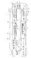
この再生装置の外観は図1に示される。
1は再生装置本体を示す。
2は再生装置1の正面パネルに設けられ、前面側に図2に示すディスクトレイ30が引き出されるディスク装填部である。ディスクトレイ30は5枚のディスクを平面方向に並べて搭載することができ、ルーレット状に回転することで再生されるディスクが選択される。
3は液晶パネルによる表示部であり、再生装置の動作状態、モード、選択されているディスクのナンバ、演奏時間等が表示される。
The appearance of this reproducing apparatus is shown in FIG.
この正面パネルにはユーザーの操作のための各種キーが設けられている。4は電源オン/オフキーである。
5は再生キーである。この再生キーは上述したプレイバックコントロール動作の際の選択キー(選択エンターキー)を兼ねている。
6は一時停止キー、7は停止キー、8はイジェクトキーである。
Various keys for user operations are provided on the front panel.
6 is a pause key, 7 is a stop key, and 8 is an eject key.
9はディスク選択キーである。このディスク選択キーは『D1』〜『D5』として5つのキーが用意され、ディスクトレイ上に収納される5枚のディスクに対応している。例えば『D1』のキーが押されると、ディスクトレイ上で第1の収納位置に収納されているディスクが内部の光学ヘッドの位置にローディングされ、再生されることになる。 9 is a disk selection key. There are five disc selection keys “D1” to “D5” corresponding to five discs stored on the disc tray. For example, when the “D1” key is pressed, the disk stored in the first storage position on the disk tray is loaded at the position of the internal optical head and reproduced.
10,11はAMS操作のためのキーであり、即ち10はトラックナンバの小さい方向への頭出しキー(後方頭出しキー)、11はトラックナンバの大きい方向への頭出しキー(前方頭出しキー)である。また、後方頭出しキー10はプレビアスキーを兼ねており、上述したプレイバックコントロール動作の際のプレビアス操作のために用いられる。さらに前方頭出しキー11はネクストキーを兼ねており、上述したプレイバックコントロール動作の際のネクスト操作のために用いられる。
12はリターンキーであり、プレイバックコントロール動作の際のリターン操作のために用いられる。
10 and 11 are keys for AMS operation, that is, 10 is a cue key in the direction of small track number (rear cue key), and 11 is a cue key in the direction of larger track number (front cue key). ). Further, the backward cue key 10 also serves as a pre-via ski and is used for a pre-via operation in the above-described playback control operation. Further, the forward cue key 11 also serves as a next key, and is used for the next operation in the playback control operation described above.
A
13は+/−選択キーであり、プレイバックコントロール動作の際のメニュー画面上での選択操作に用いられる。すなわちメニュー画面に対して+/−選択キー13で選択肢番号を選択していき、或る選択肢番号を指定した時点で再生キー5でセレクト操作を行なうことで、メニューに対する選択が完了されることになる。
14はディスクスキップキー、15はディスクイクスチェンジキーである。
16〜19はプレイモードの選択キーであり、16は通常再生モードキーである。プレイバックコントロール機能の付加されたディスクが再生される際には、通常再生モードキー16を押すと、自動的にプレイバックコントロール動作に入ることになる。
17はシャッフル再生モードキー、18はプログラム再生モードキーである。 また19はPBCオフキーであり、このPBCオフキー19によりPBCモードがオフとされる。つまり、プレイバックコントロール機能の付加されたディスクが装填されているときにPBCオフキー19が押されると、PBCモードによるメニュー再生動作から通常の連続再生動作に移ることになる。
14 is a disc skip key, and 15 is a disc exchange key.
20はダイジェストキー、21はダイジェストモードキーである。ダイジェストキー20により、収納されている各ディスクについてのダイジェスト映像を表示させることができる。またダイジェストモードキー21により、プレイバックコントロール機能の付加されたディスクについてのダイジェスト映像をメニュー画像とするか、トラック内の映像とするかを選択することができる。
20 is a digest key, and 21 is a digest mode key. The digest key 20 can be used to display a digest video for each stored disc. The digest
22はブックマーク登録キー、23はブックマーク再生キーである。再生中にユーザーがブックマーク登録キーを押すことにより、その再生地点が登録される。そしてその後は、ブックマーク再生キー23を押すことで、その地点から再生させることができる。例えばブックマーク登録キー22により1つのディスクについて5箇所の再生ポイントを指定して登録することができる。
22 is a bookmark registration key, and 23 is a bookmark reproduction key. When the user presses the bookmark registration key during reproduction, the reproduction point is registered. After that, the bookmark can be reproduced from that point by pressing the
そしてブックマーク再生キー23を押してから、登録されたブックマークポイントのうちの1つを選択すると、その再生ポイントから再生が開始される。登録されたブックマークポイントの選択には例えば+/−選択キー13とセレクトキー5が用いられる。
Then, when one of the registered bookmark points is selected after pressing the
24は赤外線受信部である。図示しないリモートコマンダーから赤外線によりコマンド信号が送信されると、この赤外線受信部24で受信され、電気信号に変換されて操作情報として内部のシステムコントローラに取り込まれる。
2 回路ブロック
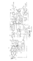
図2に再生装置の内部の構成を示す。
図2において30はディスクトレイである。ディスクトレイ30には5枚のディスクを搭載できるように収納位置301 〜305 が設けられている。そして、ディスクトレイ30はモータ31によって回転されるように構成されており、この回転動作によって或る1つの収納位置30x が光学ヘッド34の位置に送られる。つまり、その収納位置30x に積載されているディスクが光学ヘッド34の位置にローディングされる。32はディスク位置センサであり、このディスク位置センサ32の出力により、システムコントローラ53は現在のローディング状態、つまりどの収納位置30x が光学ヘッド34の位置にあるか、を把握することができる。
2 circuit blocks
FIG. 2 shows the internal configuration of the playback apparatus.
In FIG. 2, 30 is a disk tray. The
ローディングされたディスクは、スピンドルモータ33により回転駆動されるようにチャッキングされる。そしてそのディスクは、スピンドルモータ33によって回転されながら光学ヘッド34によってレーザ光が照射され、その反射光によって情報が読み取られる。
The loaded disk is chucked so as to be rotated by a
光学ヘッド34はレーザ出力手段としてのレーザダイオード、偏向ビームスプリッタや対物レンズ等からなる光学系、及び反射光を検出するためのディテクタが搭載されている。対物レンズ34aは2軸機構34bによってディスク半径方向及びディスクに接離する方向に変位可能に保持されている。また、35は光学
ヘッド34をディスク半径方向に駆動するスレッド機構を示す。
The
再生動作によって、光学ヘッド34によりディスクから検出された情報はRFアンプ36に供給される。RFアンプ36は供給された情報の演算処理により、再生RF信号、トラッキングエラー信号、フォーカスエラー信号等を抽出する。そして、抽出された再生RF信号はデコーダ部38に供給されEFM復調、エラー訂正が行なわれる。またP,Qチャンネルサブコードデータが取り出されてシステムコントローラ53に供給される。
Information detected from the disk by the
また、トラッキングエラー信号、フォーカスエラー信号はサーボ回路37に供給される。サーボ回路37は供給されたトラッキングエラー信号、フォーカスエラー信号や、システムコントローラ53からのトラックジャンプ指令、アクセス指令、スピンドルモータ33の回転速度検出情報等により各種サーボ駆動信号を発生させ、2軸機構34b及びスレッド機構35を制御してフォーカス及びトラッキング制御を行ない、またスピンドルモータ33を一定線速度(CLV)に制御する。
The tracking error signal and the focus error signal are supplied to the
39はCD−ROMデコーダである。再生中のディスクがビデオCDなど、いわゆるCD−ROMの範中に入るものである場合は、CD−ROMデコーダ39はCD−ROMフォーマットに従ってデコード処理を行なう。
そして、CD−ROMデコーダ39によってデコードされた信号のうち、前述したプレイバックコントロールのための情報などの各種ディスク情報はシステムコントローラ53のRAM53aに取り込まれる。
Of the signals decoded by the CD-
また、CD−ROMデコーダ39によってデコードされたオーディオデータは、MPEGオーディオデコーダ40に供給される。MPEGオーディオデコーダ40はオーディオRAM41を用いながら所定タイミングでデコード及びデコードオーディオ信号出力を行なう。
さらに、CD−ROMデコーダ39によってデコードされたビデオデータは、MPEGビデオデコーダ42に供給される。MPEGビデオデコーダ42はビデオRAM43を用いながら所定タイミングでデコード及びデコードビデオ信号出力(RGB出力)を行なう。
The audio data decoded by the CD-
Further, the video data decoded by the CD-
44は再生されるディスクの種別に応じて切り換えられるスイッチ部である。 再生されているディスクがCD−DAであった場合は、その再生信号としてはデコーダ部38でEFM復調、CIRC等のデコード処理されることでデジタルオーディオ信号が得られる。
CD−DA再生中には、システムコントローラ53はスイッチ部44をt1 端子に接続させている。従ってデコーダ部38からのデジタルオーディオ信号はD/A変換器45でアナログオーディオ信号に変換され、オーディオ出力端子46から後段の増幅回路又はアンプなどの外部機器に出力される。
During CD-DA playback, the
また再生中のディスクがビデオCDであった場合は、オーディオデータはMPEGオーディオデコーダ40から得られる。ビデオCD再生中には、システムコントローラ53はスイッチ部44をt2 端子に接続させている。従ってMPEGオーディオデコーダ40からのデジタルオーディオ信号はD/A変換器45でアナログオーディオ信号に変換され、オーディオ出力端子46から後段の増幅回路又はアンプなどの外部機器に出力される。
If the disc being reproduced is a video CD, the audio data is obtained from the
ビデオCDの再生の際には、MPEGビデオデコーダ42の出力としてRGB映像データが得られる。このRGB映像データはD/A変換器47でRGBアナログ信号とされる。そしてRGB/NTSCエンコーダ48に供給され、RGB信号がNTSC方式のコンポジット映像信号に変換される。そしてスイッチ部49のt2 端子に供給される。
When playing a video CD, RGB video data is obtained as an output of the
ビデオCD再生中には、システムコントローラ53はスイッチ部49をt2 端子に接続させており、従ってNTSC方式のコンポジット映像信号はOSD処理部50を介してビデオ出力端子51からモニタ装置等に供給され、映像出力が実行される。システムコントローラ53からの指示に基づくOSD処理部50の動作により、出力映像に所定のスーパーインポーズ表示を行なうことができる。
During video CD playback, the
ところで、再生されるディスクがCD−DAであって、しかもそれがCD−Gであった場合は、サブコードのR〜Wチャンネルから静止画像データが読み出される。この静止画像データはCD−Gデコーダ52に供給されてデコードされ、NTSC方式のコンポジット映像信号(静止画)として出力される。CD−DA再生中には、スイッチ部49はt1 端子に接続され、従ってCD−Gから再生された映像信号はOSD処理部50を介してビデオ出力端子51からモニタ装置等に供給され、映像出力が実行される。この場合もOSD処理部50により、出力映像に所定のスーパーインポーズ表示を行なうことができる。
By the way, when the disc to be reproduced is CD-DA and it is CD-G, still image data is read from the R to W channels of the subcode. The still image data is supplied to the CD-
54はRAMであり、バックアップ電源55によりメモリデータのバックアップがとられている。このRAM54はブックマークポイントの登録データなど、電源オフの際に消失させてはならないデータが記憶される。もちろんEEP−ROMなどを用いてもよい。
56はユーザー操作に供される操作入力部であり、図1に示した各種操作キー(5〜23)と、赤外線受信部24(及びリモートコマンダー)がこれに相当する。また、ディスクから再生動作を行なう際には、ディスクに記録されている管理情報、即ちTOCやサブコードデータが読み出され、システムコントローラ53に供給されるが、システムコントローラ53はこれらの管理情報に応じて表示部3に再生時間表示等を行なうことになる。
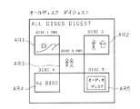
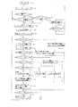
[IV.オールディスクダイジェスト動作]
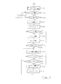
1 第1の動作処理例
以上のように複数枚のディスクを装填できるチャンジャー型の再生装置1では、ユーザーは収納位置301 〜305 のそれぞれにどのようなディスクが搭載されているかを簡単に知ることができるようにすると操作上非常に好適である。
そこで本実施例では、オールディスクダイジェスト表示という機能を再生装置1に付加し、このオールディスクダイジェスト表示で各ディスクの内容を一覧して判別できるようにしている。
[IV. All disk digest operation]
1 First operation processing example
As described above, in the changer
Therefore, in the present embodiment, a function called “all disc digest display” is added to the reproducing
このオールディスクダイジェスト表示動作について第1の動作例を以下、説明していく。
オールディスクダイジェスト表示としては、例えば図3に示すように、収納位置301 〜305 に搭載されているディスクを『DISC 1』〜『DISC 5』として、各ディスクからの再生映像等を所定の表示エリアAR1〜AR5にペーストしたオールディスクダイジェスト映像を生成し、モニタ装置に表示するものである。
A first operation example of this all-disc digest display operation will be described below.
As the all disc digest display, for example, as shown in FIG. 3, the discs mounted in the storage positions 30 1 to 30 5 are set as “
オールディスクダイジェストのためのシステムコントローラ53の処理を図6に示す。
電源オンとされると(F100)、システムコントローラ53はまず内部のタイマーをリセットし、カウントスタートさせる(F101)。このタイマー処理は、オールディスクダイジェスト動作の実行判別を行なうためのものである。
もし、電源オンの状態でなんらユーザーの操作が行なわれずに設定されたタイマー時間が経過すると、自動的にオールディスクダイジェスト動作を開始する (F102→F106→F107) 。
The processing of the
When the power is turned on (F100), the
If the set timer time elapses without any user operation while the power is on, the all-disc digest operation is automatically started (F102 → F106 → F107).
タイマー時間が経過する前に何らかの操作が行なわれた場合は、まずそれがオールディスクダイジェスト操作であるか否かを判別する(F103)。オールディスクダイジェスト操作とは、ユーザーがダイジェストキー20を押した場合である。ダイジェストキー20が押された場合とは、ユーザーがオールディスクダイジェスト動作を要求した場合であり、従ってオールディスクダイジェスト動作を開始する (F103→F107) 。 If any operation is performed before the timer time elapses, it is first determined whether or not it is an all-disc digest operation (F103). The all-disc digest operation is when the user presses the digest key 20. The case where the digest key 20 is pressed is a case where the user requests an all-disc digest operation, and therefore the all-disc digest operation is started (F103 → F107).
再生、ディスク選択などの他の操作であった場合は、操作に応じた所要の動作処理を実行し(F104)、その動作が終了したらステップF101に戻る。
即ちこの実施例では、ユーザーがオールディスクダイジェスト操作を行なった場合か、もしくは何等動作が行なわれないまま所定時間経過したときに、オールディスクダイジェスト動作が開始されるものとなる。
If the operation is another operation such as reproduction or disc selection, a required operation process corresponding to the operation is executed (F104), and when the operation is completed, the process returns to step F101.
In other words, in this embodiment, the all disc digest operation is started when the user performs the all disc digest operation or when a predetermined time elapses without any operation being performed.
オールディスクダイジェスト動作が開始されると(F107)、システムコントローラ53はまずビデオRAM43を初期化する(F108)。そして、ディスクトレイ30上の任意のディスクをチャッキングする(F109)。このチャッキングは、その時点で最も光学ヘッド34に近い収納位置30x に搭載されているディスクを行なえば良い。
When the all-disc digest operation is started (F107), the
そして、収納位置30x にディスクが存在するか否かを判別する(F110)。ディスクの有無はローディング位置におけるセンサ手段を設けるようにすればよい。もしくは、このフローでは処理順序が逆になるが、起動してみてTOCが読めたか否かでディスク有無を判別するようにしてもよい。 Then, it is determined whether or not a disk exists at the storage position 30 x (F110). The presence or absence of a disk may be provided with sensor means at the loading position. Alternatively, in this flow, the processing order is reversed, but it may be determined whether or not there is a disk depending on whether the TOC can be read after starting.
ディスクが存在してチャッキングが完了したら、ディスクを起動する(F111)。即ちスピンドルモータ33を起動してディスクを回転させるとともに、光学ヘッド34からレーザ照射を開始させる。そして、このときのディスクから読み取られた情報により、まずディスクの判別を行なう(F112)。
When the disk exists and chucking is completed, the disk is started (F111). That is, the
ディスクの判別は図7の処理で行なう。
まずディスクのリードインエリアを再生して、TOCデータを読み込む(F201,F202) 。ここで、図19で説明したように、POINTが『A0』のブロックにおいてPSEC=『20』となっていれば、そのディスクはXA仕様のCD−ROMである。一方、PSEC=『00』であればCD−DA、PSEC=『10』であればCD−Iである。
Disc discrimination is performed by the processing of FIG.
First, the lead-in area of the disc is reproduced and the TOC data is read (F201, F202). Here, as described with reference to FIG. 19, if PSEC = “20” in a block whose POINT is “A0”, the disk is a CD-ROM of XA specification. On the other hand, if PSEC = “00”, it is CD-DA, and if PSEC = “10”, it is CD-I.
そこで、POINT『A0』のブロックのPSECを確認し(F203)、『20』でXA仕様のCD−ROMと判別されればステップF204に進む。そして絶対時間アドレス00:04:00からのディスクインフォメーションのデータを読み込む。図22に示したディスクインフォメーションにおいて、先頭のシステム認識子に『VIDEO CD』と記録されていれば、そのディスクはビデオCDと判別される。この場合ステップF205からF206に進む。そして、システム認識子に続くバージョン番号を確認する。 Therefore, the PSEC of the point “A0” block is confirmed (F203). If “20” is determined as the CD-ROM of the XA specification, the process proceeds to step F204. Then, the disc information data from the absolute time address 00:04:00 is read. In the disc information shown in FIG. 22, if “VIDEO CD” is recorded in the head system identifier, the disc is determined to be a video CD. In this case, the process proceeds from step F205 to F206. Then, the version number following the system identifier is confirmed.
バージョン番号が『$0200』であれば、バージョン2.00のディスクであり、この場合プレイバックコントロール機能が付加されている場合がある。そこでステップF207でディスクインフォメーションの第45〜48バイト目のPSDサイズのデータを確認する。前述したようにプレイバックコントロール機能が付加されている場合はPSDエリアのサイズが示され、プレイバックコントロール機能が付加されていなければPSDサイズは『0』とされている。 If the version number is “$ 0200”, the disc is version 2.00, and in this case, a playback control function may be added. In step F207, the PSD size data of the 45th to 48th bytes of the disc information is confirmed. As described above, when the playback control function is added, the size of the PSD area is shown. When the playback control function is not added, the PSD size is set to “0”.
従って、PSDサイズが『0』でなければ、そのディスクはプレイバックコントロール機能が付加されたメニュー付きのビデオCDと判別される(F208)。
一方、PSDサイズが『0』の場合は、プレイバックコントロール機能が付加されていない、つまりメニューのないビデオCDと判別される(F210)。
また、ステップF206でバージョン番号が『$0101』であれば、バージョン1.01のディスクであり、この場合プレイバックコントロール機能が付加されていることはないため、メニューのないビデオCDと判別される(F210)。
Therefore, if the PSD size is not “0”, the disc is discriminated as a video CD with a menu with a playback control function added (F208).
On the other hand, when the PSD size is “0”, it is determined that the video CD has no playback control function, that is, no menu (F210).
If the version number is “$ 0101” in step F206, it is a disc of version 1.01, and in this case there is no playback control function added, so it is determined that the video CD has no menu (F210). ).
ステップF203でPSEC=『20』でないとされた場合は、ステップF211でPSEC=『00』であるか否かを確認し、さらにステップF212でサブQデータ内のコントロールデータ(Q1 〜Q4 )が『x0xx』であるか否かを確認する。このステップF211及びF212で肯定結果が出た場合は、そのディスクはCD−DAであると判別される(F213)。 If it is determined in step F203 that PSEC = “20”, it is checked in step F211 whether PSEC = “00”, and in step F212, control data (Q 1 to Q 4 ) in the sub-Q data is checked. Is “x0xx”. If a positive result is obtained in steps F211 and F212, it is determined that the disc is a CD-DA (F213).
ステップF211、F212、F205、F209のいづれかで否定結果が出た場合は、そのディスクは本実施例の再生装置に適応しない他の種のディスクであるため、無効と判断される(F214)。 If a negative result is obtained in any of steps F211, F212, F205, and F209, it is determined that the disc is invalid because it is another type of disc that is not applicable to the playback apparatus of this embodiment (F214).
図6のステップF112において図7の処理でディスク判別がなされたらステップF113〜F115で処理が分岐される。そして無効ディスクであればディスクが搭載されてないものとして扱う。 If the disk is discriminated in the process of FIG. 7 in step F112 of FIG. 6, the process branches in steps F113 to F115. If it is an invalid disk, it is treated as if the disk is not installed.
ディスクがビデオCDであって、しかもPBCディスク、即ちメニュー付きのビデオCDであった場合は、ステップF116に進んでメニュー表示モードであるか否かを判別する。
これは、メニュー付きディスクの場合には、ユーザーはオールディスクダイジェスト画像としてメニュー映像を用いるか、もしくはトラック内のIピクチャーを用いるかを選択できるようにしたものである。このモードはダイジェストメニューキー21によってユーザーが予め選択しておく。
If the disc is a video CD and is a PBC disc, that is, a video CD with a menu, the process proceeds to step F116 to determine whether or not the menu display mode is set.
In the case of a disc with a menu, the user can select whether to use a menu video as an all-disc digest image or an I picture in a track. This mode is selected by the user in advance using the
そしてメニュー表示モードであったら、ステップF117に進んで、そのディスクから初期メニュー映像データを読出、ビデオRAM43に取り込む。初期メニュー映像データとは、通常、リストIDが『1』であるセレクションリストもしくはプレイリストによって指定されるセグメントプレイアイテムの映像データである。
If it is in the menu display mode, the process proceeds to step F117, where the initial menu video data is read from the disk and taken into the
一方、メニュー表示モードでなければ、Iピクチャーを取り込む(F118)。これは通常、トラック#2の最初のIピクチャーである。ただし、トラックの最初のIピクチャーとせずに、そのトラック内で2〜3秒後のデータとなるIピクチャーとしてもよい。また、トラック#2に限らず、ディスク内の特定のIピクチャーを選んでもよい。
On the other hand, if it is not the menu display mode, the I picture is captured (F118). This is usually the first I picture of
ステップF117又はF118で、メニュー付きディスクからそのディスクの内容を示す代表となる映像データを取り込んだら、ステップF121でオールディスクダイジェスト映像データ内でそのディスクに対応する位置にPBCディスクであることを示す『PBC』の文字がOSD表示されるように制御する。 In step F117 or F118, when the representative video data indicating the contents of the disc is fetched from the disc with the menu, in step F121, it is indicated that the PBC disc is in the position corresponding to the disc in the all disc digest video data. Control is performed so that the characters “PBC” are displayed in an OSD manner.
そして、ステップF122でシステムコントローラ53は読み込んだ初期メニュー映像又はIピクチャーとなるデータに対して所定画素間引などで画像縮小を行なって、その映像データをビデオRAM43における現在読み込み中のディスクのナンバに対応した位置ARxにペーストする。なお、ビデオRAM43のデータはそのまま映像出力されているため、このペースト処理時点で、モニタ装置では、その縮小画像が所定の表示位置ARxにあらわれることになる。
In step F122, the
一方、ステップF115で、現在の読み込み対象のディスクがビデオCDであるがメニューの無いものであると判別された場合は、そのディスクから代表となるIピクチャーを取り込む(F119)。これも、トラック#2の最初のIピクチャーとすればよい。もしくはトラックの最初のIピクチャーとせずに、そのトラック内で2〜3秒後のデータとなるIピクチャーとしてもよい。
そして、ステップF122に進み、システムコントローラ53は読み込んだIピクチャーデータを縮小して、その映像データをビデオRAM43における現在読み込み中のディスクのナンバに対応した位置ARxにペーストする。
On the other hand, if it is determined in step F115 that the current disc to be read is a video CD but no menu, a representative I picture is taken from that disc (F119). This may also be the first I picture of
In step F122, the
さらにディスクがCD−DAであった場合はステップF114からステップF120に進む。この場合、ディスク内に映像データは存在しないため、システムコントローラ53は内部のROMに保持しているCD−DA用の固定の画像データをビデオRAM43に送る。そしてステップF122に進み、その固定の映像データをビデオRAM43における現在読み込み中のディスクのナンバに対応した位置ARxにペーストする。
If the disc is a CD-DA, the process proceeds from step F114 to step F120. In this case, since there is no video data in the disc, the
ディスクが装填されていなかった場合は、ステップF123に進む。ここでシステムコントローラ53はOSD処理部50に指示を出し、オールディスクダイジェスト表示映像上で、現在対象となっている収納位置(ディスクナンバ)に対応した表示位置ARxに『NO DISC』の表示を実行させる。
なお、『NO DISC』の表示に替えて、いわゆる青画面表示等、他の表示状態としてもよい。
また、無効ディスクであった場合はステップF126に進んで、システムコントローラ53はOSD処理部50に指示を出し、オールディスクダイジェスト表示映像上で、現在対象となっている収納位置(ディスクナンバ)に対応した表示位置ARxに『DISC ERROR』等の表示を実行させる。なお、無効ディスクの場合にもディスクが装填されていなかった場合と同様にステップF123に進むようにしてもよい。
If no disc is loaded, the process proceeds to step F123. Here, the
Instead of displaying “NO DISC”, other display states such as a so-called blue screen display may be used.
If the disk is an invalid disk, the process proceeds to step F126, where the
或るディスクについてこの処理を終了したら、続いてステップF125で次のディスクをチャッキングする。即ちディスクトレイ30を回転させ、次の収納位置30x+1 についてのディスクをローディングする。そしてステップF110からの処理を繰り返す。
5枚のディスク(収納位置301 〜305 )に対してステップF110からの処理が終了した時点(F124→YES)で、接続されたモニタ装置には、例えば図3のようなオールディスクダイジェスト映像が出力されていることになる。
When this process is completed for a certain disk, the next disk is chucked in step F125. That is, the
When the processing from step F110 is completed (F124 → YES) for five discs (storage positions 30 1 to 30 5 ), the connected monitor device displays an all-disc digest video, for example, as shown in FIG. Is output.
この図3は、収納位置301 及び303 のディスクがPBCディスク、収納位置302 のディスクがPBC機能のないビデオCD、収納位置305 のディスクがCD−DAが搭載されており、収納位置304 にはディスクが搭載されていなかった場合のオールディスクダイジェスト表示である。なお、ダイジェスト表示オードはメニュー表示モードとされていた場合である。
FIG. 3 shows that the storage positions 30 1 and 30 3 are loaded with a PBC disk, the
このため、収納位置301 及び303 のディスク、即ち『DISC 1』及び『DISC 3』に対応して、各ディスクから読み込まれた初期メニュー映像が表示位置AR1、AR3に表示されている。さらに、PBCディスクであることを示すため、表示位置AR1、AR3に近接して『PBC』という文字がOSD表示されている。
Therefore, the initial menu video read from each disk is displayed at the display positions AR1 and AR3 corresponding to the disks at the storage positions 30 1 and 30 3 , that is, “
また、収納位置302 のディスク、即ち『DISC 2』に対応してIピクチャーとしての映像が表示位置AR2に表示される。
さらに、『DISC 4』については表示位置AR4に『NO DISC』と表示され、また表示位置AR5には、『DISC 5』はCD−DAであって音楽用ディスクであることを示す固定の映像が示されている。
In addition, an image as an I picture is displayed at the display position AR2 corresponding to the disk at the
Further, “
このようにオールディスクダイジェスト表示が実行されることで、ユーザーは装填されている各ディスクを一覧して認識することができる。このため、例えばオールディスクダイジェスト表示を見ながら再生させたいディスクのナンバーを確認し、ディスク選択キー9で選択して再生させることができる。従って再生させたいディスクのナンバーが分からずに、各ディスクを再生していって所望のディスクを探していくという煩雑な操作は必要なくなる。
また、このオールディスクダイジェスト表示はユーザーが要求した場合のみでなく、動作がなされていない状態で自動的に行なわれるため、ユーザーは特にダイジェスト操作を行なわなくてもディスク内容を確認できる。
By executing the all-disc digest display in this way, the user can list and recognize each loaded disc. For this reason, for example, the number of the disk to be reproduced can be confirmed while viewing the all-disc digest display, and can be selected and reproduced by the
Further, since the all disc digest display is automatically performed not only when requested by the user but also when no operation is performed, the user can check the disc contents without performing a digest operation.
ところで、ダイジェストモードが、メニュー表示モードでない場合は、図4のようなオールディスクダイジェストとなる。即ち、PBCディスクである『DISC 1』及び『DISC 3』についてもIピクチャーが表示される。この場合、PBCディスクであるか否かは『PBC』というOSD表示で区別される。 なお、PBCディスクであることの表示は『PBC』という文字に限らず、他の文字やシンボルとしてもよい。
By the way, when the digest mode is not the menu display mode, an all-disc digest as shown in FIG. 4 is obtained. That is, the I picture is also displayed for “
ユーザーがPBCディスクについてもオールディスクダイジェスト表示でIピクチャーを表示させたい場合には、ダイジェストモードキー21を操作しておくことで、この図4のように表示させることができ、ユーザーの要望に対応することができる。
If the user wants to display the I picture with the all-disc digest display even for the PBC disc, it can be displayed as shown in FIG. 4 by operating the digest
2 第2の動作処理例
次に、同様のオールディスクダイジェスト表示動作について第2の動作例を説明する。
この動作例が上記第1の動作例と異なる点は、まずPBCディスクについては必ずメニュー映像を表示するようにすることである。また、ディスクがCD−DAであった場合には、場合によってはそれがCD−Gである場合もある。そこでCD−Gの場合は、静止画像データを用いてオールディスクダイジェストを生成するようにしている。なお、CD−Gの場合に、その静止画像データを用いてオールディスクダイジェストを生成するには、図2の回路ブロックを多少変形する必要がある。即ちCD−Gデコーダ52の出力をビデオRAM43に取り込むことができるように回路構成を変更することになる。
2 Second operation processing example
Next, a second operation example of the same all-disc digest display operation will be described.
The difference between this operation example and the first operation example is that the menu video is always displayed for the PBC disc. Further, if the disc is a CD-DA, it may be a CD-G depending on the case. Therefore, in the case of CD-G, an all-disc digest is generated using still image data. In the case of CD-G, in order to generate an all-disc digest using the still image data, it is necessary to slightly modify the circuit block of FIG. That is, the circuit configuration is changed so that the output of the CD-
この第2の動作例のオールディスクダイジェストのためのシステムコントローラ53の処理を図8に示す。
ただし、ステップF300〜F312までは図6のステップF100〜F112までの処理と同様であるため、図示するのみにとどめ、説明を省略する。
FIG. 8 shows the processing of the
However, since steps F300 to F312 are the same as the processing from steps F100 to F112 in FIG. 6, they are only illustrated and will not be described.
図8のステップF312において前述した図7の処理でディスク判別がなされたらステップF313〜F316で処理が分岐される。そして無効ディスクであればディスクが搭載されてないものとして扱う。 If the disk is discriminated in the process of FIG. 7 described above in step F312 of FIG. 8, the process is branched in steps F313 to F316. If it is an invalid disk, it is treated as if the disk is not installed.
ディスクがビデオCDであって、しかもPBCディスク、即ちメニュー付きのビデオCDであった場合は、ステップF315からF317に進んで、そのディスクから初期メニュー映像データを読み出し、ビデオRAM43に取り込む。初期メニュー映像データとは、通常、リストIDが『1』であるセレクションリストもしくはプレイリストによって指定されるセグメントプレイアイテムの映像データである。
If the disc is a video CD and is a PBC disc, that is, a video CD with a menu, the process proceeds from step F315 to F317 to read initial menu video data from the disc and take it into the
そしてステップF317で、メニュー付きディスクからそのディスクの内容を示す代表となるメニュー映像データを取り込んだら、ステップF318でオールディスクダイジェスト映像データ内でそのディスクに対応する位置にPBCディスクであることを示す『PBC』の文字がOSD表示されるように制御する。 In step F317, when representative menu video data indicating the contents of the disc is fetched from the disc with menu, in step F318, the PBC disc is indicated at the position corresponding to the disc in the all disc digest video data. Control is performed so that the characters “PBC” are displayed in an OSD manner.
そして、ステップF322でシステムコントローラ53は読み込んだ初期メニュー映像データに対して所定画素の間引などで画像縮小を行なって、その映像データをビデオRAM43における現在読み込み中のディスクのナンバに対応した位置ARxにペーストする。なお、ビデオRAM43のデータはそのまま映像出力されているため、このペースト処理時点で、モニタ装置では、その縮小画像が所定の表示位置ARxにあらわれることになる。
In step F322, the
一方、ステップF315で、現在の読み込み対象のディスクがビデオCDであるがメニューの無いものであると判別された場合は、そのディスクから代表となるIピクチャーを取り込む(F319)。即ちトラック#2の最初のIピクチャー、もしくはトラック#2の2〜3秒後のデータとなるIピクチャーを取り込む。
そして、ステップF322に進み、システムコントローラ53は読み込んだIピクチャーデータを縮小して、その映像データをビデオRAM43における現在読み込み中のディスクのナンバに対応した位置ARxにペーストする。
On the other hand, if it is determined in step F315 that the disc to be read is a video CD but no menu, a representative I picture is taken from that disc (F319). That is, the first I picture of
In step F322, the
さらにディスクがCD−DAであった場合は、ステップF316でそのディスクがCD−Gであるか否かを判別する。この判別には実際にトラックを再生してみてサブコードデータとしてのR〜Wチャンネルに静止画像データが記録されているか否かを判別することになる。 If the disc is a CD-DA, it is determined in step F316 whether the disc is a CD-G. For this determination, it is determined whether or not still image data is recorded in the RW channels as subcode data by actually reproducing the track.
そしてCD−Gでなく、通常の音楽用のCD−DAであったら、ステップF320に進む。この場合、ディスク内に映像データは存在しないため、システムコントローラ53は内部のROMに保持しているCD−DA用の固定の画像データをビデオRAM43に送る。そしてステップF322に進み、その固定の映像データをビデオRAM43における現在読み込み中のディスクのナンバに対応した位置ARxにペーストする。
If it is not a CD-G but a normal music CD-DA, the process proceeds to step F320. In this case, since there is no video data in the disc, the
CD−Gであった場合にはステップF321に進み、CD−Gデコーダ52でデコードされた画像データをビデオRAM43に取り込み、縮小してビデオRAM43における現在読み込み中のディスクのナンバに対応した位置ARxにペーストする。
If it is CD-G, the process proceeds to step F321, and the image data decoded by the CD-
ディスクが装填されていなかった場合は、ステップF323に進む。ここでシステムコントローラ53はOSD処理部50に指示を出し、オールディスクダイジェスト表示映像上で、現在対象となっている収納位置(ディスクナンバ)に対応した表示位置ARxに『NO DISC』の表示を実行させる。
また、無効ディスクであった場合はステップF326に進んで、システムコントローラ53はOSD処理部50に指示を出し、オールディスクダイジェスト表示映像上で、現在対象となっている収納位置(ディスクナンバ)に対応した表示位置ARxに『DISC ERROR』等の表示を実行させる。なお、無効ディスクの場合にもディスクが装填されていなかった場合と同様にステップF323に進むようにしてもよい。
If no disc is loaded, the process proceeds to step F323. Here, the
If the disk is an invalid disk, the process proceeds to step F326, where the
或るディスクについてこの処理を終了したら、続いてステップF325で次のディスクをチャッキングする。即ちディスクトレイ30を回転させ、次の収納位置30x+1 についてのディスクをローディングする。そしてステップF310からの処理を繰り返す。
When this process is completed for a certain disk, the next disk is chucked in step F325. That is, the
このような処理により5枚のディスク(収納位置301 〜305 )に対してステップF110からの処理が終了した時点 (F324→YES)で、接続されたモニタ装置には、例えば図3のようなオールディスクダイジェスト映像が出力されていることは上述した動作例1と同様である。 When the processing from step F110 is completed (F324 → YES) for five disks (storage positions 30 1 to 30 5 ) by such processing, the connected monitor device has, for example, as shown in FIG. The same all-disc digest video is output as in the operation example 1 described above.
ただし、この図3では表示位置AR5については、『DISC 5』がオーディオディスクである旨の表示となっているが、図8の動作例の場合、この『DISC 5』がCD−Gであったら、そのCD−Gから読み込まれた静止画像が表示されていることになる。
また、この動作例の場合、PBCディスクについては必ずメニュー映像画表示されるため、図4のような表示状態になることはない。
However, in FIG. 3, the display position AR5 is displayed to indicate that “
In the case of this operation example, a menu video image is always displayed on the PBC disc, so that the display state as shown in FIG.
この場合も、オールディスクダイジェスト表示が実行されることで、ユーザーは装填されている各ディスクを一覧して認識することができる。
特にCD−Gについても確認できることになる。
Also in this case, by executing the all disc digest display, the user can list and recognize each loaded disc.
In particular, CD-G can also be confirmed.
以上、実施例のオールディスクダイジェスト動作を説明してきたが、本発明におけるオールディスクダイジェスト動作としては各種変形例が考えられることはいうまでもない。
例えばオールディスクダイジェスト表示における各ディスクに対応する表示位置AR1〜AR5のレイアウトはもちろん変更可能である。さらにチャンジャー再生装置としては収納可能な枚数が4枚以下もしくは6枚以上となることもあるが、オールディスクダイジェスト表示レイアウトはディスク収納可能枚数に応じて設定されることは当然である。
Although the all-disc digest operation of the embodiment has been described above, it goes without saying that various modifications can be considered as the all-disc digest operation in the present invention.
For example, the layout of the display positions AR1 to AR5 corresponding to each disk in the all disk digest display can of course be changed. Further, the changer playback apparatus may store four or fewer sheets or six or more sheets, but the all-disc digest display layout is naturally set according to the number of disks that can be stored.
また、オールディスクダイジェストとしての動作を説明したが、ほぼ同様の方式で図5(a)のように1枚のディスクについて各トラックの先頭のIピクチャーを取り出してディスクダイジェスト画面を表示したり、図5(b)のように或るトラック内でいくつかのIピクチャ−を取り出してトラック内容が大まかに分かるようなダイジェスト表示を行なうようにすることも考えられる。
Although the operation as an all-disc digest has been described, in the same manner, as shown in FIG. 5 (a), the first I picture of each track is extracted for one disc and a disc digest screen is displayed. As shown in FIG. 5B, it is also possible to take out some I pictures in a certain track and perform a digest display so that the track contents can be roughly understood.
[V.オールディスクダイジェスト表示時の早送り動作]
1 第1の動作処理例
次に、上述のようにオールディスクダイジェスト表示を実行している際の早送り動作について説明する。
オールディスクダイジェスト表示により、ユーザーは収納位置301 〜305 のそれぞれにどのようなディスクが搭載されているかを簡単に知ることができるが、さらに、各ディスクの内容について或る程度詳しく知りたい場合がある。
そこで本実施例では、オールディスクダイジェスト表示を行なっている場合に、各ディスク又は特定のディスクについて早送り再生を実行し、その早送り映像がオールディスクダイジェスト表示内で表示されるようにしている。
[V. Fast-forward operation when displaying all disc digest]
1 First operation processing example
Next, the fast-forward operation when the all-disc digest display is executed as described above will be described.
The all-disc digest display allows the user to easily know what type of disc is installed in each of the storage positions 30 1 to 30 5 , but if he wants to know some details about the contents of each disc. There is.
Therefore, in this embodiment, when all-disc digest display is being performed, fast-forward playback is executed for each disc or specific disc, and the fast-forward video is displayed in the all-disc digest display.
このオールディスクダイジェスト表示時の早送り動作としての第1の動作例を図9、図10、図11を用いて説明していく。
今、再生装置1に5枚のビデオCDが収納されているとし、上述したオールディスクダイジェスト動作により、モニタ装置では図10(a)のような表示が実行されているとする。この状態を図9ではステップF400として示している。
A first operation example as a fast-forwarding operation at the time of displaying the all disc digest will be described with reference to FIGS.
Now, it is assumed that five video CDs are stored in the
この時点で例えばユーザーが早送り操作を行なうと、システムコントローラ53の処理は図9のステップF400からF401を介してF402に進む。
なお、この場合の早送り操作のための操作キーとしては、例えば前方頭出しキー11を用いるようにすればよい。
また、早送り操作が行なわれなくても、オールディスクダイジェスト表示を行
なって所定時間経過したら自動的にステップF402からの処理に進むようにしてもよい。
ステップF402では、まず変数xを1にセットする。そして、収納位置30x に搭載されているディスクをローディングする(F403)。従ってまず最初に収納位置301 に搭載されている第1のディスクがローディングされる。
At this time, for example, when the user performs a fast-forward operation, the processing of the
In this case, as an operation key for the fast-forward operation, for example, the front cue key 11 may be used.
Even if the fast-forward operation is not performed, the all-disc digest display may be performed and the process may automatically proceed from step F402 when a predetermined time has elapsed.
In step F402, a variable x is first set to 1. Then, the disk loaded at the
ここで、収納位置30x にディスクが存在するか否かを判別し(F404)、ディスクが存在する場合、つまりローディングができた場合はディスクを起動する(F405)。ディスク有無の検出はローディング位置におけるセンサ手段で検出するか、もしくは、このフローでは処理順序が逆になるが、起動してみてTOCが読めたか否かでディスク有無を判別するようにすればよい。ディスクが無かった場合はステップF413に進み、次のディスクに対する処理に移る。 Here, it is determined whether or not a disk exists at the storage position 30 x (F404). If a disk exists, that is, if loading is completed, the disk is activated (F405). The presence / absence of the disk is detected by the sensor means at the loading position, or the processing order is reversed in this flow, but the presence / absence of the disk may be determined based on whether or not the TOC can be read after starting. If there is no disk, the process proceeds to step F413 to proceed to processing for the next disk.
ステップF405のディスクを起動処理としては、スピンドルモータ33を起動してディスクを回転させるとともに、光学ヘッド34からレーザ照射を開始させる。そして、このときのディスクから読み取られた情報により、ディスクの判別を行なう(F405)。ディスクの判別は前述した図7の処理で行なう。
In the start processing of the disk in step F405, the
図7の処理でディスク判別がなされたらステップF407に進み、そのディスクがビデオCDであった場合は、ステップF408に進んで、そのディスクからのデータ読取を実行する。このデータ読取は早送り再生の処理となる。
なお、ビデオCDでなかった場合はステップF413に進み、次のディスクに対する処理に移る。
If the disc is determined in the process of FIG. 7, the process proceeds to step F407, and if the disc is a video CD, the process proceeds to step F408 to read data from the disc. This data reading is a fast-forward playback process.
If it is not a video CD, the process proceeds to step F413, and the process for the next disk is started.
ステップF408からの早送り再生としては、システムコントローラ53は光学ヘッド34の動作として、図11に模式的に示すような動作を実行させる。
早送り再生時には、ディスクから離散的にIピクチャーを抽出して、これを表示させるものである。このため、図11のように通常再生動作を実行させてディスク30からIピクチャーを探し出す。そして、IピクチャーがみつかったらこれをMPEGビデオデコーダ42でデコードさせるとともに、光学ヘッド34に数トラックのトラックジャンプを実行させる。トラックジャンプを終了したら、また通常再生動作を実行させてIピクチャーを探す。このような動作を繰り返すことで早送り再生が実行される。
As fast-forward playback from step F408, the
During fast-forward playback, I pictures are discretely extracted from the disc and displayed. Therefore, the normal reproduction operation is executed as shown in FIG. When an I picture is found, it is decoded by the
ステップF408のディスクデータ読取動作は、即ちIピクチャーを探すための動作となる。
なお、この読取時には通常の再生時と同様の読取を行なうため、Iピクチャーを見つけるまでに図16に示したオーディオセクターAについても読み出すことができる。そこで、オーディオセクターAから読み込まれた音声データについてはMPEGオーディオデコーダ40からスイッチ部44、D/A変換器45を介して出力する。これにより、早送り時に離散的ではあるが、通常速度の音声出力が得られることになる。
The disk data reading operation in step F408 is an operation for searching for an I picture.
Since this reading is performed in the same manner as in normal reproduction, the audio sector A shown in FIG. 16 can also be read before the I picture is found. Therefore, the audio data read from the audio sector A is output from the
読取動作でIピクチャーが見つかり、MPEGビデオデコーダ42でデコードできた場合は、ステップF410からF411に進む。そして、デコードしたIピクチャーデータに対して所定画素間引などで画像縮小を行なって、その映像データをビデオRAM43における現在読み込み中のディスクのナンバに対応した位置ARxにペーストする。ビデオRAM43のデータはそのまま映像出力されているため、このペースト処理時点で、モニタ装置では、その縮小画像が表示位置ARxにあらわれることになる。
最初は第1のディスクについての処理のため、縮小された映像データは表示位置AR1にペーストされることになり、これによって図10(a)のオールディスクダイジェスト映像が図10(b)のように変化する。
If the I picture is found by the reading operation and can be decoded by the
Initially, because of the processing for the first disc, the reduced video data is pasted at the display position AR1, so that the all disc digest video in FIG. 10 (a) becomes as shown in FIG. 10 (b). Change.
次にシステムコントローラ53は光学ヘッド34に所定トラック数のトラックジャンプを実行させ、トラックジャンプが終了したらステップF408に戻って再び次のIピクチャーの読込及び音声出力を実行させる。
そしてIピクチャーがデコードできれば、同様にステップF411に進んで、Iピクチャーデータを縮小して表示位置AR1にペーストする。これによりオールディスクダイジェスト映像が図10(c)のように変化する。
Next, the
If the I picture can be decoded, the process similarly proceeds to step F411, where the I picture data is reduced and pasted to the display position AR1. As a result, the all-disc digest video changes as shown in FIG.
以降同様にトラックジャンプと読取動作を繰り返し、読み取られたIピクチャーデータを縮小して表示位置AR1にペーストしていく処理を繰り返すことになる (F408〜F412) 。以上の動作により、オールディスクダイジェスト映像は図10(a)→(b)→(c)→・・・・→(d)と変化していく。
つまり、オールディスクダイジェスト映像内で、第1のディスクに対応する表示位置AR1のみが第1のディスクからの早送り映像として出力されることになる。また、このとき離散的に通常速度の音声も再生出力されている。これによりユーザーは第1のディスクの内容について短時間でより詳しく知ることができる。なお、このとき、第2〜第5のディスクに対応する表示位置AR2〜AR5については、映像は変化していない。
Thereafter, the track jump and the reading operation are repeated in the same manner, and the process of reducing the read I picture data and pasting it to the display position AR1 is repeated (F408 to F412). With the above operation, the all-disc digest video changes in the order of FIG. 10 (a) → (b) → (c) →.
That is, only the display position AR1 corresponding to the first disk in the all-disc digest video is output as a fast-forward video from the first disk. Also, at this time, normal speed audio is also reproduced and output discretely. Thereby, the user can know the contents of the first disc in more detail in a short time. At this time, the image is not changed at the display positions AR2 to AR5 corresponding to the second to fifth disks.
ステップF408〜F412の処理で第1のディスクについて早送り再生を実行し、その早送り映像を表示位置AR1に表示させていき、図10(d)の状態になった直後に、光学ヘッド34によるデータ読取がリードアウトに達し、つまり第1のディスクの早送り再生が終了したとする。
すると処理はステップF409からF413に進み、変数xをインクリメントする。
そして変数x=6でない場合は、ステップF403に戻る。つまり第1のディスクの早送り再生が終了した場合は、変数X=2となり、ステップF403で収納位置302 に収納されている第2のディスクがローディングされることになる。
In step F408 to F412, fast-forward playback is executed for the first disk, and the fast-forward video is displayed at the display position AR1. Immediately after the state shown in FIG. Reaches the lead-out, that is, fast-forward playback of the first disc is completed.
Then, the process proceeds from step F409 to F413, and the variable x is incremented.
If the variable x is not 6, the process returns to step F403. That is, when the fast-forward reproduction of the first disk is terminated, variable X = 2, and the second disk stored in the
そしてステップF404以降の同様の処理が第2のディスクについて実行され、これによってオールディスクダイジェスト映像は、図10(d)の状態から図10(e)の状態に変化し、さらに図10(f)→・・・・→(g)と変化していくことになる。つまり、表示位置AR1については第1のディスクからの最後のIピクチャーが表示されたまま固定され、第2のディスクに対応する表示位置AR2において、早送り映像が表示されていくことになる。 Then, the same processing after step F404 is executed for the second disc, whereby the all disc digest video changes from the state of FIG. 10D to the state of FIG. 10E, and further, FIG. → ・ ・ ・ ・ → (g) will change. That is, the display position AR1 is fixed while the last I picture from the first disk is displayed, and the fast-forward video is displayed at the display position AR2 corresponding to the second disk.
さらに図10(g)の状態で第2のディスクの早送り再生が終了したら、ステップF413で変数xがインクリメントされ、ステップF403で収納位置303 に収納されている第3のディスクがローディングされる。そして、同様にステップF404以降の処理で第3のディスクに対して早送り再生が実行され、図10(g)→(h)のように第3のディスクに対応する表示位置AR3において、早送り映像が表示されていくことになる。表示位置AR2については第2のディスクからの最後の映像で固定される。
以上の動作が第4のディスク、第5のディスクについても順次実行され、各早送り映像が表示位置AR4,AR5に表示される。
Further, when the fast-forward playback of the second disk is completed in the state of FIG. 10G, the variable x is incremented in step F413, and the third disk stored in the
The above operation is sequentially executed for the fourth disc and the fifth disc, and each fast-forward video is displayed at the display positions AR4 and AR5.
このようにオールディスクダイジェスト表示内で各ディスクについて早送り再生表示が実行されることで、ユーザーは装填されている各ディスクの内容を短時間でより詳しく知ることができる。これにより、再生させたいディスクを選択する操作もより容易なものとなる。 Thus, by performing fast-forward playback display for each disk within the all-disc digest display, the user can know the contents of each loaded disk in more detail in a short time. As a result, the operation of selecting a disc to be reproduced becomes easier.
なお、この図9の動作例では、ディスクがビデオCDであった場合のみ早送り再生を実行するようにしているが、CD−Gであった場合にも同様に早送り再生を実行させるようにしてもよい。また音声データのみのCD−DAの場合でも、映像は例えば図3の表示位置AR5に示したような映像で固定し、音声のみを早送り再生させて出力するようにしてもよい。 In the operation example of FIG. 9, fast-forward playback is executed only when the disc is a video CD, but fast-forward playback is also executed when the disc is a CD-G. Good. Further, even in the case of CD-DA with only audio data, the video may be fixed, for example, as shown in the display position AR5 in FIG. 3, and only the audio may be played back and output.
また、ビデオCDの早送り再生時にディスクから読み取ることができた音声データについても出力するとしたが、音声データの出力は行なわないようにしてもよい。
さらに、各ディスクについてはリードアウトに達するまで早送り再生を実行するようにしたが、ディスクの途中まで早送り再生した時点で次のディスクに移るようにしてもよい。
また、早送り再生中にユーザー操作に基づいて次のディスクの早送り再生に移るようにしてもよい。例えばユーザーが或る程度の早送り画面をみただけでそのディスクの内容が分かった場合などは、何らかの操作により最後まで早送りさせずに次のディスクの早送りに移るようにすれば、より迅速に各ディスクの内容を確認することができるようになる。
また、早送り再生速度をユーザーが可変操作できるようにしてもよい。
Further, although audio data that could be read from the disc during fast-forward playback of a video CD is output, audio data may not be output.
Further, fast-forward reproduction is executed for each disc until the lead-out is reached, but it is also possible to move to the next disc when fast-forward reproduction is performed to the middle of the disc.
Further, the fast-forward playback of the next disc may be started based on the user operation during the fast-forward playback. For example, if the user understands the contents of the disc by just looking at a certain fast-forward screen, it is possible to move to each disc more quickly by moving to the next disc fast-forward without performing fast-forward to the end by some operation. You can check the contents of.
Further, the fast-forward playback speed may be variably operated by the user.
2 第2の動作処理例
次に、オールディスクダイジェスト表示時の早送り動作について第2の動作例を説明する。
上記第1の動作例では、収納されている全てのディスクについて連続的に早送り再生させるようにしたが、この第2の動作例ではオールディスクダイジェスト映像を見たユーザーが、その中から特定のディスクを選んで、そのディスクについてのみ早送り映像を出力するようにしたものである。つまり、ユーザーは内容を詳しく確認したいディスクのみを選択してオールディスクダイジェスト映像内で早送り再生させることができるようにしている。
2 Second operation processing example
Next, a second operation example will be described for the fast-forward operation during the all-disc digest display.
In the first operation example, all the stored disks are continuously fast-forwarded and reproduced. In this second operation example, a user who has viewed the all-disc digest video can select a specific disk from among them. And fast-forward video is output only for that disc. In other words, the user can select only the disk whose contents are to be confirmed in detail and play it back in the all-disc digest video.
この第2の動作例のオールディスクダイジェスト表示時の早送り動作のためのシステムコントローラ53の処理を図12に示す。
オールディスクダイジェスト表示を実行している時点(F500)において、ユーザーは早送り操作をすることができるとともに、早送りさせるディスクを選択することができる。例えば前方頭出しキー11を押した後に、ディスク選択キー9などを用いて選択するようにする。
FIG. 12 shows the processing of the
At the time of executing the all-disc digest display (F500), the user can perform a fast-forward operation and can select a disc to be fast-forwarded. For example, after the
システムコントローラ53は、早送り操作がされた場合はステップF501からF502に進み、もしディスク選択がなされなかった場合は、上述した図9のステップF402に進む。つまり、第1の動作例による処理に移る。
ディスクが選択された場合は、ステップF503に進み、変数xに選択されたナンバ(ディスクナンバ)をセットする。例えば第3のディスクが選択されたと仮定して説明していく。
If the fast-forward operation is performed, the
If a disk is selected, the process proceeds to step F503, and the selected number (disk number) is set in the variable x. For example, the description will be made assuming that the third disk is selected.
次に収納位置30x 、つまり収納位置303 に収納されている第3のディスクをローディングする(F504)。
そして、ステップF505〜F513の処理で、そのディスクについて図9のステップF404〜F412までの処理と同様の処理を行なう。
ステップF505〜F513の各処理については図9で説明したものと同様であるため詳細な説明は省略するが、即ちこの場合は、選択された第3のディスクについて早送り再生を実行させ、順次読み取れたIピクチャーデータを縮小して表示位置AR3にペーストしていくことになる。
Next, the third disk stored in the
Then, in the processing of steps F505 to F513, the same processing as the processing from steps F404 to F412 of FIG.
Since the processes in steps F505 to F513 are the same as those described with reference to FIG. 9, detailed description thereof is omitted. That is, in this case, the fast-forward playback is executed for the selected third disk, and the reading is sequentially performed. The I picture data is reduced and pasted to the display position AR3.
従ってオールディスクダイジェスト映像では、表示位置AR3のみが第3のディスクからの早送り再生映像として表示されていくことになり、表示位置AR1,AR2,AR4,AR5は固定されたままである。
そして、そのディスクについてリードアウトに達したら(F510)、処理を終了する。
Therefore, in the all-disc digest video, only the display position AR3 is displayed as a fast-forward playback video from the third disc, and the display positions AR1, AR2, AR4, and AR5 remain fixed.
When the lead-out is reached for the disc (F510), the process is terminated.
この動作例によれば、ユーザーは詳しく内容を確認したいディスクについてのみ、オールディスクダイジェスト映像内で早送り再生させることができ、見る必要のないディスクについては早送り再生を実行させないことで、より短時間で所望のディスクの内容が確認できるという利点が生ずる。 According to this operation example, the user can perform fast-forward playback within the all-disc digest video only for discs whose contents are to be checked in detail, and by not performing fast-forward playback for discs that do not need to be viewed, it can be performed in a shorter time. The advantage is that the contents of the desired disc can be confirmed.
なお、この図12の動作例でも、ビデオCDであった場合のみでなく、ユーザーに指定されたディスクがCD−Gや音声データのみのCD−DAであった場合でも、映像又は音声の早送り再生を行なうようにしてもよい。
さらに、指定されたディスクについてリードアウトに達するまで早送り再生を実行するのではなく、ディスクの途中まで早送り再生した時点で自動的に終了させたり、ユーザー操作に基づいて早送り再生を終了させるようにしてもよい。
また、早送り再生速度をユーザーが可変操作できるようにしてもよい。
In the operation example of FIG. 12, not only when the disc is a video CD, but also when the disc specified by the user is a CD-G or a CD-DA with only audio data, fast-forward playback of video or audio. May be performed.
Furthermore, instead of performing fast-forward playback until the lead-out is reached for the specified disc, it is automatically terminated when fast-forward playback is performed halfway through the disc, or fast-forward playback is terminated based on user operations. Also good.
Further, the fast-forward playback speed may be variably operated by the user.
1 再生装置、3 表示部、5 再生キー(セレクトキー)、
9 ディスク選択キー、10 後方頭出しキー(プリビアスキー)
2 前方頭出しキー(ネクストキー)、12 リターンキー、
3 +/−選択キー、20 ダイジェストキー、
21 ダイジェストモードキー、22 ブックマーク登録キー、
23 ブックマーク再生キー、24 赤外線受信部、30 ディスクトレイ、
301 〜305 収納位置、34 光学ヘッド、36 RFアンプ、
37 サーボ回路、38 デコーダ部、39 CD−ROMデコーダ、
40 MPEGオーディオデコーダ、41 オーディオRAM、
4 MPEGビデオデコーダ、43 ビデオRAM、
44,49 スイッチ部、45,47 D/A変換器、
46 オーディオ出力端子、48 RGB/NTSCエンコーダ、
50 OSD処理部、51 ビデオ出力端子、 52 CD−Gデコーダ、
53 システムコントローラ、54 RAM、55 バックアップ電源、
56 操作部、AR1〜AR5 表示位置、S1,S2 セレクションリスト、
P1〜P5 プレイリスト、PB1〜PB10 再生出力
1 playback device, 3 display section, 5 playback key (select key),
9 Disc selection key, 10 backward cue key (previa ski)
2 forward key (next key), 12 return key,
3 +/- selection key, 20 digest key,
21 digest mode key, 22 bookmark registration key,
23 Bookmark playback key, 24 Infrared receiver, 30 Disc tray,
30 1 to 30 5 storage position, 34 optical head, 36 RF amplifier,
37 servo circuit, 38 decoder section, 39 CD-ROM decoder,
40 MPEG audio decoder, 41 audio RAM,
4 MPEG video decoder, 43 video RAM,
44, 49 switch part, 45, 47 D / A converter,
46 audio output terminal, 48 RGB / NTSC encoder,
50 OSD processing unit, 51 video output terminal, 52 CD-G decoder,
53 System controller, 54 RAM, 55 Backup power supply,
56 operation unit, AR1 to AR5 display position, S1, S2 selection list,
P1-P5 playlist, PB1-PB10 playback output
Claims (1)
上記収納手段に収納された複数のディスクから所望のディスクを選択する選択手段と、
上記収納手段に収納された各々のディスクから映像データを読み出す再生手段と、
上記再生手段にて再生された、上記収納手段に収納された各々のディスクの映像データを同一画面上に表示できるように制御する映像出力制御手段と、
上記映像出力制御手段によって表示された同一画面上の各々のディスクの映像データから所定のディスクに対応する映像データを選択する第1の操作手段と、
上記第1の操作手段にて選択された所定のディスクに対応する映像データの早送り再生を指示する第2の操作手段と、
上記第2の操作手段の早送り再生操作に応じて、上記第1の操作手段にて選択された所定のディスクの映像データの早送り再生を行うように再生手段を制御する制御手段と、
を備え、
上記再生手段にて早送り再生された映像データを上記第1の操作手段にて選択された所定のディスクに対応する表示領域に表示することを特徴とする再生装置。
Storage means capable of storing a plurality of discs on which video or audio data is recorded;
Selection means for selecting a desired disk from a plurality of disks stored in the storage means;
Reproduction means for reading video data from each disk stored in the storage means;
Video output control means for controlling the video data of the respective discs stored in the storage means reproduced by the playback means to be displayed on the same screen;
First operating means for selecting video data corresponding to a predetermined disk from the video data of each disk on the same screen displayed by the video output control means;
Second operating means for instructing fast-forward playback of video data corresponding to the predetermined disc selected by the first operating means;
Control means for controlling the reproduction means so as to perform fast-forward reproduction of the video data of the predetermined disc selected by the first operation means in response to the fast-forward reproduction operation of the second operation means;
With
A reproducing apparatus for displaying video data fast-forwarded and reproduced by the reproducing means in a display area corresponding to a predetermined disc selected by the first operating means.
Priority Applications (1)
| Application Number | Priority Date | Filing Date | Title |
|---|---|---|---|
| JP2005082170A JP2005183003A (en) | 1994-07-04 | 2005-03-22 | Reproducing apparatus |
Applications Claiming Priority (2)
| Application Number | Priority Date | Filing Date | Title |
|---|---|---|---|
| JP17317194 | 1994-07-04 | ||
| JP2005082170A JP2005183003A (en) | 1994-07-04 | 2005-03-22 | Reproducing apparatus |
Related Parent Applications (1)
| Application Number | Title | Priority Date | Filing Date |
|---|---|---|---|
| JP2002152122A Division JP3685153B2 (en) | 1994-07-04 | 2002-05-27 | Playback device |
Related Child Applications (1)
| Application Number | Title | Priority Date | Filing Date |
|---|---|---|---|
| JP2006006611A Division JP2006164512A (en) | 1994-07-04 | 2006-01-13 | Playing back device |
Publications (1)
| Publication Number | Publication Date |
|---|---|
| JP2005183003A true JP2005183003A (en) | 2005-07-07 |
Family
ID=34796922
Family Applications (1)
| Application Number | Title | Priority Date | Filing Date |
|---|---|---|---|
| JP2005082170A Pending JP2005183003A (en) | 1994-07-04 | 2005-03-22 | Reproducing apparatus |
Country Status (1)
| Country | Link |
|---|---|
| JP (1) | JP2005183003A (en) |
-
2005
- 2005-03-22 JP JP2005082170A patent/JP2005183003A/en active Pending
Similar Documents
| Publication | Publication Date | Title |
|---|---|---|
| JP3339210B2 (en) | Playback device | |
| JP3575063B2 (en) | Playback device and playback method | |
| KR100353101B1 (en) | Video playback apparatus for keeping continous data | |
| JP3593698B2 (en) | Reproduction device and reproduction method | |
| KR100384612B1 (en) | Method and apparatus for reproducing a recording medium | |
| KR100366478B1 (en) | Playback apparatus and access method with index search function | |
| US5970205A (en) | Method and apparatus for performing variable speed reproduction of compressed video data | |
| JP3381431B2 (en) | Playback device and playback method | |
| JP3685153B2 (en) | Playback device | |
| KR100401402B1 (en) | Record carrier playback device | |
| JPH0888829A (en) | Reproducing device | |
| JPH08111082A (en) | Reproducing device | |
| JP2005183003A (en) | Reproducing apparatus | |
| JP2006164512A (en) | Playing back device | |
| JP2000105964A (en) | Reproducer | |
| JP4207978B2 (en) | Playback apparatus and playback method | |
| JP2000100138A (en) | Reproducing device | |
| JPH0887823A (en) | Reproducer | |
| JP2006269072A (en) | Recording medium | |
| KR0182442B1 (en) | Memory stop and memory reproducing method when playback controlling of interactive disc | |
| JP2004296081A (en) | Recording medium | |
| JPH0898147A (en) | Reproduction device |
Legal Events
| Date | Code | Title | Description |
|---|---|---|---|
| A521 | Written amendment |
Free format text: JAPANESE INTERMEDIATE CODE: A821 Effective date: 20050322 |
|
| A621 | Written request for application examination |
Free format text: JAPANESE INTERMEDIATE CODE: A621 Effective date: 20050322 |
|
| A131 | Notification of reasons for refusal |
Free format text: JAPANESE INTERMEDIATE CODE: A131 Effective date: 20051129 |
|
| A521 | Written amendment |
Free format text: JAPANESE INTERMEDIATE CODE: A523 Effective date: 20060113 |
|
| A02 | Decision of refusal |
Free format text: JAPANESE INTERMEDIATE CODE: A02 Effective date: 20060207 |
|
| A521 | Written amendment |
Free format text: JAPANESE INTERMEDIATE CODE: A821 Effective date: 20060210 |
|
| A521 | Written amendment |
Free format text: JAPANESE INTERMEDIATE CODE: A523 Effective date: 20060303 |
|
| A911 | Transfer of reconsideration by examiner before appeal (zenchi) |
Free format text: JAPANESE INTERMEDIATE CODE: A911 Effective date: 20060322 |
|
| A912 | Removal of reconsideration by examiner before appeal (zenchi) |
Free format text: JAPANESE INTERMEDIATE CODE: A912 Effective date: 20060414 |
|
| A521 | Written amendment |
Free format text: JAPANESE INTERMEDIATE CODE: A523 Effective date: 20080407 |