JP2005182016A - Method and apparatus for processing video data of display device - Google Patents
Method and apparatus for processing video data of display device Download PDFInfo
- Publication number
- JP2005182016A JP2005182016A JP2004359520A JP2004359520A JP2005182016A JP 2005182016 A JP2005182016 A JP 2005182016A JP 2004359520 A JP2004359520 A JP 2004359520A JP 2004359520 A JP2004359520 A JP 2004359520A JP 2005182016 A JP2005182016 A JP 2005182016A
- Authority
- JP
- Japan
- Prior art keywords
- dithering
- dither mask
- mask pattern
- frame
- data
- Prior art date
- Legal status (The legal status is an assumption and is not a legal conclusion. Google has not performed a legal analysis and makes no representation as to the accuracy of the status listed.)
- Abandoned
Links
- 238000000034 method Methods 0.000 title claims abstract description 24
- 238000001514 detection method Methods 0.000 claims description 10
- 238000003672 processing method Methods 0.000 claims description 9
- 230000003068 static effect Effects 0.000 abstract 1
- 238000009792 diffusion process Methods 0.000 description 19
- 239000000758 substrate Substances 0.000 description 7
- 238000010586 diagram Methods 0.000 description 6
- 238000013507 mapping Methods 0.000 description 6
- OAICVXFJPJFONN-UHFFFAOYSA-N Phosphorus Chemical compound [P] OAICVXFJPJFONN-UHFFFAOYSA-N 0.000 description 4
- 230000004888 barrier function Effects 0.000 description 3
- 229910052751 metal Inorganic materials 0.000 description 3
- 239000002184 metal Substances 0.000 description 3
- 230000001681 protective effect Effects 0.000 description 3
- CPLXHLVBOLITMK-UHFFFAOYSA-N magnesium oxide Inorganic materials [Mg]=O CPLXHLVBOLITMK-UHFFFAOYSA-N 0.000 description 2
- 239000000395 magnesium oxide Substances 0.000 description 2
- AXZKOIWUVFPNLO-UHFFFAOYSA-N magnesium;oxygen(2-) Chemical compound [O-2].[Mg+2] AXZKOIWUVFPNLO-UHFFFAOYSA-N 0.000 description 2
- 238000005192 partition Methods 0.000 description 2
- 238000005401 electroluminescence Methods 0.000 description 1
- AMGQUBHHOARCQH-UHFFFAOYSA-N indium;oxotin Chemical compound [In].[Sn]=O AMGQUBHHOARCQH-UHFFFAOYSA-N 0.000 description 1
- 239000004973 liquid crystal related substance Substances 0.000 description 1
- 230000003287 optical effect Effects 0.000 description 1
- 238000010187 selection method Methods 0.000 description 1
- 238000004544 sputter deposition Methods 0.000 description 1
Images
Classifications
-
- G—PHYSICS
- G09—EDUCATION; CRYPTOGRAPHY; DISPLAY; ADVERTISING; SEALS
- G09G—ARRANGEMENTS OR CIRCUITS FOR CONTROL OF INDICATING DEVICES USING STATIC MEANS TO PRESENT VARIABLE INFORMATION
- G09G3/00—Control arrangements or circuits, of interest only in connection with visual indicators other than cathode-ray tubes
- G09G3/20—Control arrangements or circuits, of interest only in connection with visual indicators other than cathode-ray tubes for presentation of an assembly of a number of characters, e.g. a page, by composing the assembly by combination of individual elements arranged in a matrix no fixed position being assigned to or needed to be assigned to the individual characters or partial characters
- G09G3/2007—Display of intermediate tones
- G09G3/2059—Display of intermediate tones using error diffusion
-
- G—PHYSICS
- G09—EDUCATION; CRYPTOGRAPHY; DISPLAY; ADVERTISING; SEALS
- G09G—ARRANGEMENTS OR CIRCUITS FOR CONTROL OF INDICATING DEVICES USING STATIC MEANS TO PRESENT VARIABLE INFORMATION
- G09G3/00—Control arrangements or circuits, of interest only in connection with visual indicators other than cathode-ray tubes
- G09G3/20—Control arrangements or circuits, of interest only in connection with visual indicators other than cathode-ray tubes for presentation of an assembly of a number of characters, e.g. a page, by composing the assembly by combination of individual elements arranged in a matrix no fixed position being assigned to or needed to be assigned to the individual characters or partial characters
- G09G3/22—Control arrangements or circuits, of interest only in connection with visual indicators other than cathode-ray tubes for presentation of an assembly of a number of characters, e.g. a page, by composing the assembly by combination of individual elements arranged in a matrix no fixed position being assigned to or needed to be assigned to the individual characters or partial characters using controlled light sources
- G09G3/28—Control arrangements or circuits, of interest only in connection with visual indicators other than cathode-ray tubes for presentation of an assembly of a number of characters, e.g. a page, by composing the assembly by combination of individual elements arranged in a matrix no fixed position being assigned to or needed to be assigned to the individual characters or partial characters using controlled light sources using luminous gas-discharge panels, e.g. plasma panels
- G09G3/288—Control arrangements or circuits, of interest only in connection with visual indicators other than cathode-ray tubes for presentation of an assembly of a number of characters, e.g. a page, by composing the assembly by combination of individual elements arranged in a matrix no fixed position being assigned to or needed to be assigned to the individual characters or partial characters using controlled light sources using luminous gas-discharge panels, e.g. plasma panels using AC panels
- G09G3/291—Control arrangements or circuits, of interest only in connection with visual indicators other than cathode-ray tubes for presentation of an assembly of a number of characters, e.g. a page, by composing the assembly by combination of individual elements arranged in a matrix no fixed position being assigned to or needed to be assigned to the individual characters or partial characters using controlled light sources using luminous gas-discharge panels, e.g. plasma panels using AC panels controlling the gas discharge to control a cell condition, e.g. by means of specific pulse shapes
-
- G—PHYSICS
- G09—EDUCATION; CRYPTOGRAPHY; DISPLAY; ADVERTISING; SEALS
- G09G—ARRANGEMENTS OR CIRCUITS FOR CONTROL OF INDICATING DEVICES USING STATIC MEANS TO PRESENT VARIABLE INFORMATION
- G09G3/00—Control arrangements or circuits, of interest only in connection with visual indicators other than cathode-ray tubes
- G09G3/20—Control arrangements or circuits, of interest only in connection with visual indicators other than cathode-ray tubes for presentation of an assembly of a number of characters, e.g. a page, by composing the assembly by combination of individual elements arranged in a matrix no fixed position being assigned to or needed to be assigned to the individual characters or partial characters
- G09G3/2007—Display of intermediate tones
- G09G3/2018—Display of intermediate tones by time modulation using two or more time intervals
- G09G3/2022—Display of intermediate tones by time modulation using two or more time intervals using sub-frames
-
- G—PHYSICS
- G09—EDUCATION; CRYPTOGRAPHY; DISPLAY; ADVERTISING; SEALS
- G09G—ARRANGEMENTS OR CIRCUITS FOR CONTROL OF INDICATING DEVICES USING STATIC MEANS TO PRESENT VARIABLE INFORMATION
- G09G3/00—Control arrangements or circuits, of interest only in connection with visual indicators other than cathode-ray tubes
- G09G3/20—Control arrangements or circuits, of interest only in connection with visual indicators other than cathode-ray tubes for presentation of an assembly of a number of characters, e.g. a page, by composing the assembly by combination of individual elements arranged in a matrix no fixed position being assigned to or needed to be assigned to the individual characters or partial characters
- G09G3/2007—Display of intermediate tones
- G09G3/2044—Display of intermediate tones using dithering
- G09G3/2051—Display of intermediate tones using dithering with use of a spatial dither pattern
- G09G3/2055—Display of intermediate tones using dithering with use of a spatial dither pattern the pattern being varied in time
-
- G—PHYSICS
- G09—EDUCATION; CRYPTOGRAPHY; DISPLAY; ADVERTISING; SEALS
- G09G—ARRANGEMENTS OR CIRCUITS FOR CONTROL OF INDICATING DEVICES USING STATIC MEANS TO PRESENT VARIABLE INFORMATION
- G09G3/00—Control arrangements or circuits, of interest only in connection with visual indicators other than cathode-ray tubes
- G09G3/20—Control arrangements or circuits, of interest only in connection with visual indicators other than cathode-ray tubes for presentation of an assembly of a number of characters, e.g. a page, by composing the assembly by combination of individual elements arranged in a matrix no fixed position being assigned to or needed to be assigned to the individual characters or partial characters
- G09G3/22—Control arrangements or circuits, of interest only in connection with visual indicators other than cathode-ray tubes for presentation of an assembly of a number of characters, e.g. a page, by composing the assembly by combination of individual elements arranged in a matrix no fixed position being assigned to or needed to be assigned to the individual characters or partial characters using controlled light sources
- G09G3/28—Control arrangements or circuits, of interest only in connection with visual indicators other than cathode-ray tubes for presentation of an assembly of a number of characters, e.g. a page, by composing the assembly by combination of individual elements arranged in a matrix no fixed position being assigned to or needed to be assigned to the individual characters or partial characters using controlled light sources using luminous gas-discharge panels, e.g. plasma panels
- G09G3/288—Control arrangements or circuits, of interest only in connection with visual indicators other than cathode-ray tubes for presentation of an assembly of a number of characters, e.g. a page, by composing the assembly by combination of individual elements arranged in a matrix no fixed position being assigned to or needed to be assigned to the individual characters or partial characters using controlled light sources using luminous gas-discharge panels, e.g. plasma panels using AC panels
- G09G3/296—Driving circuits for producing the waveforms applied to the driving electrodes
-
- G—PHYSICS
- G09—EDUCATION; CRYPTOGRAPHY; DISPLAY; ADVERTISING; SEALS
- G09G—ARRANGEMENTS OR CIRCUITS FOR CONTROL OF INDICATING DEVICES USING STATIC MEANS TO PRESENT VARIABLE INFORMATION
- G09G2320/00—Control of display operating conditions
- G09G2320/02—Improving the quality of display appearance
- G09G2320/0261—Improving the quality of display appearance in the context of movement of objects on the screen or movement of the observer relative to the screen
-
- G—PHYSICS
- G09—EDUCATION; CRYPTOGRAPHY; DISPLAY; ADVERTISING; SEALS
- G09G—ARRANGEMENTS OR CIRCUITS FOR CONTROL OF INDICATING DEVICES USING STATIC MEANS TO PRESENT VARIABLE INFORMATION
- G09G2320/00—Control of display operating conditions
- G09G2320/02—Improving the quality of display appearance
- G09G2320/0266—Reduction of sub-frame artefacts
-
- G—PHYSICS
- G09—EDUCATION; CRYPTOGRAPHY; DISPLAY; ADVERTISING; SEALS
- G09G—ARRANGEMENTS OR CIRCUITS FOR CONTROL OF INDICATING DEVICES USING STATIC MEANS TO PRESENT VARIABLE INFORMATION
- G09G2320/00—Control of display operating conditions
- G09G2320/10—Special adaptations of display systems for operation with variable images
- G09G2320/103—Detection of image changes, e.g. determination of an index representative of the image change
-
- G—PHYSICS
- G09—EDUCATION; CRYPTOGRAPHY; DISPLAY; ADVERTISING; SEALS
- G09G—ARRANGEMENTS OR CIRCUITS FOR CONTROL OF INDICATING DEVICES USING STATIC MEANS TO PRESENT VARIABLE INFORMATION
- G09G3/00—Control arrangements or circuits, of interest only in connection with visual indicators other than cathode-ray tubes
- G09G3/20—Control arrangements or circuits, of interest only in connection with visual indicators other than cathode-ray tubes for presentation of an assembly of a number of characters, e.g. a page, by composing the assembly by combination of individual elements arranged in a matrix no fixed position being assigned to or needed to be assigned to the individual characters or partial characters
- G09G3/2007—Display of intermediate tones
- G09G3/2044—Display of intermediate tones using dithering
- G09G3/2051—Display of intermediate tones using dithering with use of a spatial dither pattern
-
- G—PHYSICS
- G09—EDUCATION; CRYPTOGRAPHY; DISPLAY; ADVERTISING; SEALS
- G09G—ARRANGEMENTS OR CIRCUITS FOR CONTROL OF INDICATING DEVICES USING STATIC MEANS TO PRESENT VARIABLE INFORMATION
- G09G3/00—Control arrangements or circuits, of interest only in connection with visual indicators other than cathode-ray tubes
- G09G3/20—Control arrangements or circuits, of interest only in connection with visual indicators other than cathode-ray tubes for presentation of an assembly of a number of characters, e.g. a page, by composing the assembly by combination of individual elements arranged in a matrix no fixed position being assigned to or needed to be assigned to the individual characters or partial characters
- G09G3/22—Control arrangements or circuits, of interest only in connection with visual indicators other than cathode-ray tubes for presentation of an assembly of a number of characters, e.g. a page, by composing the assembly by combination of individual elements arranged in a matrix no fixed position being assigned to or needed to be assigned to the individual characters or partial characters using controlled light sources
- G09G3/28—Control arrangements or circuits, of interest only in connection with visual indicators other than cathode-ray tubes for presentation of an assembly of a number of characters, e.g. a page, by composing the assembly by combination of individual elements arranged in a matrix no fixed position being assigned to or needed to be assigned to the individual characters or partial characters using controlled light sources using luminous gas-discharge panels, e.g. plasma panels
- G09G3/288—Control arrangements or circuits, of interest only in connection with visual indicators other than cathode-ray tubes for presentation of an assembly of a number of characters, e.g. a page, by composing the assembly by combination of individual elements arranged in a matrix no fixed position being assigned to or needed to be assigned to the individual characters or partial characters using controlled light sources using luminous gas-discharge panels, e.g. plasma panels using AC panels
Landscapes
- Engineering & Computer Science (AREA)
- Physics & Mathematics (AREA)
- Computer Hardware Design (AREA)
- General Physics & Mathematics (AREA)
- Theoretical Computer Science (AREA)
- Power Engineering (AREA)
- Plasma & Fusion (AREA)
- Control Of Indicators Other Than Cathode Ray Tubes (AREA)
- Transforming Electric Information Into Light Information (AREA)
- Control Of Gas Discharge Display Tubes (AREA)
- Picture Signal Circuits (AREA)
Abstract
Description
本発明は、表示装置のビデオデータ処理方法及び装置に係り、動映像を表示するときに発生するディザリングノイズを最小化することができるような表示装置のビデオデータ処理方法及び装置に関する。 The present invention relates to a video data processing method and apparatus for a display apparatus, and more particularly to a video data processing method and apparatus for a display apparatus that can minimize dithering noise that occurs when a moving image is displayed.
表示装置は、液晶ディスプレーパネル、エレクトロ・ルミネセンスパネルおよびプラズマディスプレイパネルなど多様に開発されて利用されている。このうち、プラズマディスプレイパネル(Plasma Display Panel;以下、「PDP」という)は、ガス放電によって発生する紫外線が蛍光体を励起させるときに蛍光体から発生する可視光線を用いて画像を表示する。かかるPDPは、今まで表示手段の主軸を成してきた陰極線管(Cathode Ray Tube;CRT)に比べて厚さが薄くて軽く、かつ高鮮明/大画面の具現が可能であるという長所がある。 Display devices have been developed and used in various ways such as liquid crystal display panels, electroluminescence panels, and plasma display panels. Among these, a plasma display panel (hereinafter referred to as “PDP”) displays an image using visible light generated from a phosphor when ultraviolet rays generated by gas discharge excite the phosphor. Such a PDP has an advantage that it is thinner and lighter than a cathode ray tube (CRT), which has been the main axis of the display means, and can realize a high definition / large screen.
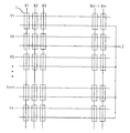
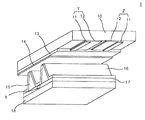
図1及び図2を参照すると、3電極交流面放電型PDPは、上部基板10上に形成された走査電極Y1〜Yn及び維持電極Zと、下部基板18上に形成されたアドレス電極X1〜Xmと、を備える。
Referring to FIGS. 1 and 2, the three-electrode AC surface discharge type PDP includes scan electrodes Y1 to Yn and sustain electrodes Z formed on the
このPDPの放電セル1は、走査電極Y1〜Yn、維持電極Z及びアドレス電極X1〜Xmの交差部毎に形成される。
The
走査電極Y1〜Ynと維持電極Zのそれぞれは、透明電極12と、透明電極12の線幅より小さい線幅を有し、透明電極の一側縁に形成される金属バス電極11と、を含む。透明電極12は、通常インジウムスズ酸化物(Indium-Tin-Oxide:ITO)で上部基板10上に形成される。金属バス電極11は、通常金属で透明電極12上に形成され、高抵抗の透明電極12による電圧降下を減らす役割を果す。走査電極Y1〜Ynと維持電極Zが形成された上部基板10には、上部誘電体層13と保護膜14が積層される。上部誘電体層13上にはプラズマ放電時に発生した壁電荷が蓄積される。保護膜14は、プラズマ放電時に発生したスパッタリングによる電極Y1〜Yn、Zと上部誘電体層13の損傷を防止すると共に、2次電子の放出効率を高める。この保護膜14としては通常酸化マグネシウム(MgO)が利用される。
Each of scan electrodes Y1 to Yn and sustain electrode Z includes
アドレス電極X1〜Xmは、走査電極Y1〜Yn及び維持電極Zと交差する方向に下部基板18上に形成される。下部基板18上には下部誘電体層17と隔壁15が形成される。下部誘電体層17と隔壁15の表面には蛍光体層16が形成される。隔壁15は、ストライプ型または格子型に形成され、放電セルを物理的に区分し、隣接した放電セル1間の電気的、光学的干渉を遮断する。蛍光体層16は、プラズマ放電時に発生した紫外線によって励起・発光して赤色、緑色または青色のいずれか一つの可視光線を発生させる。
The address electrodes X1 to Xm are formed on the
上/下部基板10、18と隔壁15との間に設けられた放電セルの放電空間には、放電のためのHe+Xe、Ne+XeまたはHe+Ne+Xeなどの不活性混合ガスが注入される。
An inert mixed gas such as He + Xe, Ne + Xe or He + Ne + Xe for discharge is injected into the discharge space of the discharge cell provided between the upper /
このようなPDPは、画像の階調(Gray Level)を具現するために一つのフレームを、発光回数の異なる複数のサブフィールドに分けて時分割駆動している。各サブフィールドは、放電を一様に起こすためのリセット期間と、放電セルを選択するためのアドレス期間と、放電回数によって階調を具現するサステイン期間と、に分けられる。例えば、256階調で画像を表示しようとする場合、1/60秒に該当するフレーム期間(16.67ms)は、8個のサブフィールドに分けられる。また、8個のサブフィールドのそれぞれは、リセット期間、アドレス期間及びサステイン期間にさらに分けられる。 Such a PDP is time-division driven by dividing one frame into a plurality of subfields having different numbers of light emission in order to realize the gray level of an image. Each subfield is divided into a reset period for causing a discharge uniformly, an address period for selecting a discharge cell, and a sustain period for realizing a gray level according to the number of discharges. For example, when an image is to be displayed with 256 gradations, a frame period (16.67 ms) corresponding to 1/60 seconds is divided into eight subfields. Each of the eight subfields is further divided into a reset period, an address period, and a sustain period.
ここで、各サブフィールドのリセット期間及びアドレス期間は各サブフィールド毎に同一である反面、サステイン期間とその放電回数はサステインパルスの数に比例して各サブフィールドにおいて2n(n=0、1、2、3、4、5、6、7)の割合で増加する。このように各サブフィールドでサステイン期間が変わるので、画像の階調を具現することができる。 Here, while the reset period and address period of each subfield are the same for each subfield, the sustain period and the number of discharges thereof are 2 n (n = 0, 1 in each subfield in proportion to the number of sustain pulses). 2, 3, 4, 5, 6, 7). As described above, since the sustain period is changed in each subfield, the gradation of the image can be realized.
図3は、従来のプラズマディスプレイパネルの駆動装置を示す図である。 FIG. 3 is a diagram illustrating a conventional plasma display panel driving apparatus.
図3を参照すると、従来のPDPの駆動装置は、ビデオデータの入力ラインとパネル40との間に接続された逆ガンマ補正部30、誤差拡散部32、ディザリング部34、サブフィールドマッピング部36、データ駆動部38を備える。
Referring to FIG. 3, the conventional PDP driving apparatus includes an inverse
逆ガンマ補正部30は、陰極線管CRTの輝度特性に合わせてガンマ補正されたデジタルビデオデータを逆ガンマ補正する。ここで、ガンマ補正部30で逆ガンマ補正されたデジタルビデオデータは線形的な輝度特性を持つようになる。
The inverse
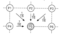
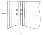
誤差拡散部32は、ガンマ補正部30からのビデオデータと誤差拡散フィルターによって算出された画素の誤差を誤差拡散係数を利用して拡散させる。例えば、図4のように現在P5画素に対する誤差拡散演算を行う場合、P5画素に隣接したP1画素に1/16の加重値を、P2画素に5/16の加重値を、P3画素に3/16の加重値を、P4画素に7/16の加重値をそれぞれ付与して誤差を拡散する。
The
ディザリング部34は、ディザマスクパターンを利用したディザリング方法によって点灯すべき放電セルを選択することにより、階調を拡張させる。このようにディザリング方法で点灯すべき放電セルを選択して階調を拡張させると、輪郭ノイズを除去することができる。例えば、ヨーロッパ特許出願第00250099.9号などには、PDPに多数のフレーム、多数のライン及び多数の列(Column)に対応する3次元ディザマスクパターンを用いて点灯すべき放電セルを選択する方法が開始されている。
The
サブフィールドマッピング部36は、ディザリング部34からの画素データのそれぞれを、予め設定されたサブフィールドパターンにマッピングして出力する。
The
データ駆動部38は、サブフィールドマッピング部36からサブフィールドパターンによってビット別に分けられて入力されるデータをラッチした後、このラッチされたデータを、1ライン分ずつ1水平ラインが駆動される期間毎にパネル40のアドレス電極ラインに供給する。パネル40は、データ駆動部38からアドレス電極ラインに供給されるデータに対応する所定の画像を表示する。
The
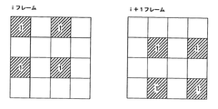
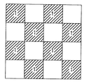
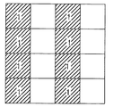
ところが、このような従来のPDPは、動映像を表示するときにディザリングノイズが発生するという問題点がある。それを詳しく説明すると、ディザリング部34はフレーム毎に相異なるディザマスクパターンを使用する。実際ディザリング部34は略2フレーム〜4フレーム単位で繰り返されるディザマスクパターンを使用する。ここで、同一階調を持つとともにi(iは自然数)番目のフレーム及びi+1番目のフレームに使用されるディザマスクパターンの“1”のディザ値は相異なる位置(例えば格子状)に配置される。例えば、i番目のフレーム及びi+1番目のフレームに使用されるディザマスクパターンは、図5のように設定される。
However, such a conventional PDP has a problem that dithering noise is generated when a moving image is displayed. More specifically, the
停止映像を表示する場合、i番目のフレーム及びi+1番目のフレームを合わせると図6のように格子状に点灯すべき放電セルが選択される。このように格子状に点灯すべき放電セルが選択されると、ノイズない画質の映像を表示することができる。しかしながら、i+1番目のフレームが1ピクセル移動する動映像を表示する場合、人の目では図7のようにディザマスクパターンがストライプ(Stripe)型に認識される。このように点灯すべき放電セルがストライプ型に認識されると、パネル40に表示される画像で特定形態のノイズが発生し、これは非常に気になる形態に認識される。
When displaying a stop image, the discharge cells to be lit in a grid pattern are selected as shown in FIG. 6 when the i-th frame and the (i + 1) -th frame are combined. Thus, when the discharge cells to be lit in a grid are selected, an image with no image quality can be displayed. However, when displaying a moving image in which the (i + 1) th frame moves by one pixel, the dither mask pattern is recognized as a stripe type as shown in FIG. When the discharge cells to be lit are recognized as a stripe type in this way, a noise of a specific form is generated in the image displayed on the
本発明は、かかる従来の問題点を解決するためのもので、その目的は、動映像を表示するときに発生するディザリングノイズを最小化することができるような表示装置のビデオデータ処理方法及び装置を提供することにある。 The present invention is intended to solve the above-described conventional problems, and an object of the present invention is to provide a video data processing method for a display device capable of minimizing dithering noise generated when displaying moving images, and To provide an apparatus.
本発明に係る表示装置のビデオデータ処理方法は、i(iは自然数)番目のフレームのデータとi+1番目のフレームのデータとを比較し、i+1番目のフレームのデータが動映像なのか停止映像なのかを判断する段階と、動映像及び停止映像の判断結果に対応して相異なるディザリング方法を適用する段階と、を含む。 The video data processing method of the display device according to the present invention compares the data of the i (i is a natural number) frame with the data of the (i + 1) th frame, and the data of the (i + 1) th frame is a moving image or a stopped image. And a step of applying different dithering methods corresponding to the determination result of the moving image and the stop image.
前記ディザリング方法を適用する段階では、自己に入力されるデータの階調値及び垂直同期信号を用いてj(jは自然数;横)×j(縦)形態に配置された多数のディザマスクパターンからいずれか一つを選択し、水平同期信号及びピクセルクロックを用いて選択されたディザマスクパターンから特定ディザ値を抽出してディザリングを行う。 In the step of applying the dithering method, a plurality of dither mask patterns arranged in the form of j (j is a natural number; horizontal) × j (vertical) using the gradation value of the data input to the self and the vertical synchronization signal. Is selected, a specific dither value is extracted from the selected dither mask pattern using the horizontal synchronization signal and the pixel clock, and dithering is performed.
前記ディザリング方法を適用する段階では、i+1番目のフレームのデータが動映像と判断されると、i+1番目のフレームで一番目のディザマスクパターンを適用するとき、j×jディザマスクパターンから一つの垂直ライン分を除去したj×j−1のディザマスクパターンを用いてディザリングを行い、一番目を除いた残りのディザマスクパターンを適用するとき、j×jディザマスクパターンを用いてディザリングを行う。 In the step of applying the dithering method, if it is determined that the data of the i + 1th frame is a moving image, when applying the first dithermask pattern in the i + 1th frame, one of the j × j dithermask patterns is applied. Dithering is performed using a j × j−1 dither mask pattern from which vertical lines have been removed, and when the remaining dither mask pattern except the first one is applied, dithering is performed using the j × j dither mask pattern. Do.
前記ディザリング方法を適用する段階では、前記i+1番目のフレームの一番目のディザマスクパターンでj×(j−1)のディザマスクパターンのみが利用できるようにピクセルクロックを制御する段階をさらに含む。 The step of applying the dithering method further includes controlling a pixel clock so that only a j × (j−1) dither mask pattern can be used in the first dither mask pattern of the i + 1 th frame.
前記ディザリング方法を適用する段階では、i+1番目のフレームのデータが停止映像と判断されると、j×jディザマスクパターンを用いてディザリングを行う。 In the step of applying the dithering method, if the data of the (i + 1) th frame is determined to be a stop video, dithering is performed using a j × j dither mask pattern.
本発明に係る表示装置のビデオデータ処理装置は、i(iは自然数)番目のフレームのデータとi+1番目のフレームのデータとを比較し、i+1番目のフレームのデータが動映像なのか停止映像なのかを判断する動き検出部と、動映像及び停止映像の判断結果に対応して相異なるディザリング方法を適用するディザリング部と、を備える。 The video data processing device of the display device according to the present invention compares the data of the i (i is a natural number) frame with the data of the i + 1 frame, and the data of the i + 1 frame is a moving image or a stop image. And a dithering unit that applies different dithering methods corresponding to the determination results of the moving image and the stop image.
前記ディザリング部は、自己に入力されるデータの階調値及び垂直同期信号を用いてj(jは自然数;横)×j(縦)形態に配置された多数のディザマスクパターンからいずれか一つを選択し、水平同期信号及びピクセルクロックを用いて選択されたディザマスクパターンから特定ディザ値を抽出してディザリングを行う。 The dithering unit uses any one of a plurality of dither mask patterns arranged in a form of j (j is a natural number; horizontal) × j (vertical) using the gradation value of the data input thereto and the vertical synchronization signal. Dithering is performed by extracting a specific dither value from the selected dither mask pattern using the horizontal synchronization signal and the pixel clock.
i+1番目のフレームのデータが動映像と判断されると、ディザリング部は、i+1番目のフレームで一番目のディザマスクパターンを適用するとき、前記j×jディザマスクパターンから一つの垂直ライン分を除去したj×j−1のディザマスクパターンを用いてディザリングを行い、一番目を除いた残りのディザマスクパターンを適用するとき、前記j×jディザマスクパターンを用いてディザリングを行う。 When the data of the i + 1th frame is determined to be a moving image, the dithering unit calculates one vertical line from the j × j dither mask pattern when applying the first dither mask pattern in the i + 1th frame. Dithering is performed using the removed j × j−1 dither mask pattern, and when the remaining dither mask pattern except the first one is applied, dithering is performed using the j × j dither mask pattern.
前記ディザリング部は、ピクセルクロックを制御してi+1番目のフレームの一番目のディザマスクパターンでj×j−1のディザマスクパターンのみを利用する。 The dithering unit controls the pixel clock to use only the j × j−1 dither mask pattern as the first dither mask pattern of the (i + 1) th frame.
i+1番目のフレームのデータが停止映像と判断されると、ディザリング部はj×jディザマスクパターンを用いてディザリングを行う。 When the data of the (i + 1) th frame is determined to be a stop video, the dithering unit performs dithering using a j × j dither mask pattern.
前記目的の外に本発明の他の目的及び特徴は、添付図を参照した実施例についての説明を通じて明白に現われるであろう。 Other objects and features of the present invention will become apparent through the description of the embodiments with reference to the accompanying drawings.
本発明に係る表示装置のビデオデータ処理方法及び装置によれば、i番目のフレームのデータとi+1番目のフレームのデータとを比較し、i+1番目のフレームが動映像なのかを判断し、i+1番目のフレームが動映像の場合、ピクセルクロックを制御してi+1番目のフレームの一番目に適用されるディザマスクパターンで一つの垂直ラインが選択されないようにディザリングを行うことにより、ノイズなしの画像を表示することができる。 According to the video data processing method and apparatus of the display device of the present invention, the i-th frame data is compared with the i + 1-th frame data to determine whether the i + 1-th frame is a moving image, and the i + 1-th frame is determined. If the frame is a moving image, the pixel clock is controlled to perform dithering so that one vertical line is not selected in the dither mask pattern applied to the first of the (i + 1) th frame. Can be displayed.
以下、図8〜図12bを参照して本発明の好適な実施例について説明する。 Hereinafter, a preferred embodiment of the present invention will be described with reference to FIGS.
図8は、本発明の実施例に係るプラズマディスプレイパネルの駆動波形を示す図である。 FIG. 8 is a diagram illustrating a driving waveform of the plasma display panel according to the embodiment of the present invention.
図8は、本発明の実施例に係るプラズマディスプレイパネルの駆動装置を示す図である。 FIG. 8 is a diagram illustrating a plasma display panel driving apparatus according to an embodiment of the present invention.
図8を参照すると、本発明の実施例に係るPDPの駆動装置は、入力ラインとパネル60との間に接続された逆ガンマ補正部50、誤差拡散部52、ディザリング部54、サブフィールドマッピング部56、データ駆動部58と、入力ラインとディザリング部54との間に接続された動き検出部62と、を備える。
Referring to FIG. 8, the driving apparatus of the PDP according to the embodiment of the present invention includes an inverse
逆ガンマ補正部50は、陰極線管CRTの輝度特性に合わせてガンマ補正されたデジタルビデオデータを逆ガンマ補正する。ここで、ガンマ補正部50で逆ガンマ補正されたデジタルビデオデータは線形的な輝度特性を持つようになる。
The inverse
誤差拡散部52は、ガンマ補正部50からのビデオデータと誤差拡散フィルターによって算出された画素との誤差を誤差拡散係数を利用して拡散させる。例えば、図4のように現在P5画素に対する誤差拡散演算を行う場合、P5画素に隣接したP1画素に1/16の加重値を、P2画素に5/16の加重値を、P3画素に3/16の加重値を、P4画素に7/16の加重値をそれぞれ付与して誤差を拡散する。また、誤差拡散部52では、誤差拡散模様が防止されるようにランダム化した加重値をP5に供給することができる。
The
ディザリング部54は、ディザマスクパターンを利用したディザリング方法で点灯すべき放電セルを選択することにより、階調を拡張させる。また、ディザリング部54は、動き検出部62の制御により、動映像の場合、ディザマスクパターンの選択方法を変更することにより、ディザリングノイズの発生を防止する。このようなディザリング部54の詳細な動作過程は後述することにする。
The dithering
動き検出部62は、フレーム単位でデータを比較して動映像の可否を判断する。また、動き検出部62は、表示される映像が動映像であると判断されると、制御信号をディザリング部54に供給する。このような動き検出部62は、i(iは自然数)番目のフレームとi+1番目のフレームのデータとを比較することにより、i+1番目のフレームが動映像なのか停止映像なのかを判断する。
The motion detection unit 62 determines whether or not a moving image is possible by comparing data in units of frames. Further, when it is determined that the displayed video is a moving video, the motion detection unit 62 supplies a control signal to the dithering
サブフィールドマッピング部56は、ディザリング部54からの画素データのそれぞれを、予め設定されたサブフィールドパターンにマッピングして出力する。
The
データ駆動部58は、サブフィールドマッピング部56から、サブフィールドパターンによってビット別に分離して入力されるデータをラッチした後、このラッチされたデータを、1ライン分ずつ1水平ラインが駆動される期間毎にパネル60のアドレス電極ラインに供給する。パネル60は、データ駆動部58からアドレス電極ラインに供給されるデータに対応する所定の画像を表示する。
The
図9は、図8に示したディザリング部54を詳しく示す図である。
FIG. 9 shows the dithering
図9を参照すると、ディザリング部54は、マスク制御部64と、マスク制御部64の出力ラインと誤差拡散部52の出力ラインとに接続されたディザマスクテーブル66と、ディザマスクテーブル66の出力ラインと誤差拡散部52の出力ラインとに接続された加算器56と、を備える。
Referring to FIG. 9, the dithering
加算器68は、ディザマスクテーブル66から供給されるディザ値を誤差拡散部52から供給される画素データの上位ビットに加える。
The
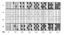
ディザマスクテーブル66は、階調別及びフレーム別に互いに異なるディザマスクパターンを格納する。例えば、図10のように4×4のセル(サブ画素)大きさを有するディザマスクパターンが入力データの下位3ビットに対応して0〜7/8のように8個の階調別に分離し、その8個のディザマスクパターンのそれぞれがさらに4個のフレーム1F〜4F別に分離することにより、ディザマスクテーブル66は総32個のディザマスクパターンを格納する。 The dither mask table 66 stores different dither mask patterns for each gradation and for each frame. For example, as shown in FIG. 10, a dither mask pattern having a 4 × 4 cell (sub-pixel) size is separated into 8 gradations such as 0 to 7/8 corresponding to the lower 3 bits of the input data. Each of the eight dither mask patterns is further divided into four frames 1F to 4F, so that the dither mask table 66 stores a total of 32 dither mask patterns.
0、1/8、2/8、3/8、4/8、5/8、6/8、7/8、7/8階調のディザマスクパターンのそれぞれでディザ値“1”に設定されたセルの数は、0個、2個、4個、6個、8個、10個、12個、14個順に増加する。また、4個のフレーム1F〜4F別にディザ値“1”に設定されたセルの位置が互いに変わる。このようなディザマスクパターンのそれぞれでの“1”の位置は、設計者の必要に応じて様々に変化できる。このようなディザマスクパターンによってディザ値“1”に該当するオン(On)セルの位置を空間的及び時間的に制御することができる。また、ディザマスクパターンでディザ値“1”の位置が階調別及びフレーム別に変わることにより、一定のディザマスクパターンの繰り返しによる格子ノイズなどのようなディザリングノイズを減らすことができる。 Dither value “1” is set for each of the dither mask patterns of 0, 1/8, 2/8, 3/8, 4/8, 5/8, 6/8, 7/8, and 7/8 gradations. The number of cells increases in the order of 0, 2, 4, 6, 8, 10, 12, and 14. In addition, the positions of the cells set to the dither value “1” for each of the four frames 1F to 4F are changed. The position of “1” in each of such dither mask patterns can be variously changed according to the needs of the designer. The position of the on (On) cell corresponding to the dither value “1” can be spatially and temporally controlled by such a dither mask pattern. Further, by changing the position of the dither value “1” in each dither mask pattern for each gradation and frame, dithering noise such as lattice noise due to repetition of a constant dither mask pattern can be reduced.
停止映像を表示するときの動作過程を説明すると、先ず、停止映像を表示する場合、動き検出部62からマスク制御部64に制御信号が供給されない。ディザマスクテーブル66は、誤差拡散部52から画素データ一部の下位ビット(例えば3ビット)の入力を受ける。また、ディザマスクテーブル66は、入力された下位ビットに該当する階調のディザマスクパターンを図10のようなディザマスクパターンの中から選択する。次いで、ディザマスクテーブル66は、選択された階調のディザマスクパターンのうちマスク制御部64が指示するフレーム及びセル位置に対応するディザ値を選択して加算器68に出力する。
The operation process when displaying the stop video will be described. First, when the stop video is displayed, the control signal is not supplied from the motion detection unit 62 to the
このために、マスク制御部64は、外部の制御部(図示せず)から入力される垂直同期信号Vをカウントして4個のフレーム1F〜4Fのうち該当フレームを指示し、水平同期信号H及び画素クロック信号Pのそれぞれをカウントして該当フレーム内における水平ライン及び垂直ライン、すなわちセル位置を指示する。ここで、停止映像を表示すると、ばパネル60の特定位置において、図11aに示したi番目のフレームのディザマスクパターンと、図11bに示したi+1番目のフレームのディザマスクパターンとが合わせられて、図11cのように格子状に点灯すべき放電セルが選択される。したがって、停止映像を表示する場合、ノイズない画像を表示することができる。
For this purpose, the
動映像を表示するときの動作過程を説明すると、先ず、動映像を表示する場合、動き検出部62からマスク制御部64に制御信号が供給される。ディザマスクテーブル66は、誤差拡散部52から入力された画素データの一部の下位ビット(例えば3ビット)の入力を受ける。また、ディザマスクテーブル66は、入力された下位ビットに該当する階調のディザマスクパターンを図10のようなディザマスクパターンの中から選択する。次いで、ディザマスクテーブル66は、選択された階調のディザマスクパターンのうちマスク制御部64が指示するフレーム及びセル位置に対応するディザ値を選択して加算器68に出力する。
The operation process when displaying a moving image will be described. First, when displaying a moving image, a control signal is supplied from the motion detection unit 62 to the
このために、マスク制御部64は、外部の制御部(図示せず)から入力される垂直同期信号Vをカウントして4個のフレーム1F〜4Fのうち該当フレームを指示し、水平同期信号H及び画素クロック信号Pのそれぞれをカウントして該当フレーム内における水平ライン及び垂直ライン、すなわちセル位置を指示する。一方、マスク制御部64は、動き検出部62から制御信号が入力される場合、図12aのように一番目のディザマスクパターン、すなわち4×4ディザマスクパターンから一つの垂直ラインを除去した4(横)×3(縦)のディザマスクパターンを用いてディザリングを行う。ここで、一番目に適用されるディザマスクパターン以外のパターンは、正常に4×4ディザマスクパターンを用いてディザリングを行う。このために、マスク制御部64は、動き検出部62から制御信号が入力されるとき、i+1番目のフレームにおいて一番目に適用されるディザマスクパターンから一つの垂直ライン分だけが選択されないようにピクセルクロックPを制御する。
For this purpose, the
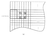
一方、i+1番目のフレームにおいて一番目に適用されるディザマスクパターンが、4×3{すなわち、本来j(jは自然数;横)×j(縦)のパターンでj(横)×(j−1)(縦)のパターンのみを適用}のディザマスクパターンを用いてディザリングを行うと、i番目のフレーム及びi+1番目のフレームのディザマスクパターンが合わせられて図12bのように人の目では格子型に認識される。すなわち、i+1番目のフレームが1ピクセル移動されたので、図12bのように人の目では格子型のパターンとして認識され、これにより動映像でもノイズない画像を表示することができる。 On the other hand, the dither mask pattern to be applied first in the (i + 1) th frame is 4 × 3 {that is, j (horizontal) × (j−1) in an original j (j is a natural number; horizontal) × j (vertical) pattern. ) (Apply only vertical pattern)}, the dither mask pattern of the i-th frame and the (i + 1) -th frame are combined to form a lattice for human eyes as shown in FIG. 12b. Recognized by the type. That is, since the i + 1-th frame has been moved by one pixel, it is recognized as a lattice pattern by the human eye as shown in FIG. 12B, so that an image without noise can be displayed even in a moving image.
Claims (10)
前記動映像及び停止映像の判断結果に対応して相異なるディザリング方法を適用する段階と、を含むことを特徴とする表示装置のビデオデータ処理方法。 comparing the data of the i (i is a natural number) frame with the data of the (i + 1) th frame to determine whether the data of the (i + 1) th frame is a moving image or a stop image;
Applying a different dithering method corresponding to the determination result of the moving image and the stop image, and a video data processing method for a display device.
前記動映像及び停止映像の判断結果に対応して相異なるディザリング方法を適用するディザリング部と、を備えることを特徴とする表示装置のビデオデータ処理装置。 a motion detection unit that compares the data of the i-th frame (i is a natural number) with the data of the i + 1-th frame and determines whether the data of the i + 1-th frame is a moving image or a stop image;
A dithering unit that applies different dithering methods corresponding to the determination results of the moving image and the stop image, and a video data processing device of a display device.
Applications Claiming Priority (1)
| Application Number | Priority Date | Filing Date | Title |
|---|---|---|---|
| KR10-2003-0091782A KR100524313B1 (en) | 2003-12-16 | 2003-12-16 | Method and Apparatus of Processing Video data For Display Apparatus |
Publications (1)
| Publication Number | Publication Date |
|---|---|
| JP2005182016A true JP2005182016A (en) | 2005-07-07 |
Family
ID=34511229
Family Applications (1)
| Application Number | Title | Priority Date | Filing Date |
|---|---|---|---|
| JP2004359520A Abandoned JP2005182016A (en) | 2003-12-16 | 2004-12-13 | Method and apparatus for processing video data of display device |
Country Status (5)
| Country | Link |
|---|---|
| US (1) | US7256794B2 (en) |
| EP (1) | EP1544841A3 (en) |
| JP (1) | JP2005182016A (en) |
| KR (1) | KR100524313B1 (en) |
| CN (1) | CN100384215C (en) |
Families Citing this family (15)
| Publication number | Priority date | Publication date | Assignee | Title |
|---|---|---|---|---|
| KR100499102B1 (en) * | 2003-12-15 | 2005-07-01 | 엘지전자 주식회사 | Apparatus and Method of Driving Plasma Display Panel |
| KR101062198B1 (en) * | 2004-04-09 | 2011-09-05 | 삼성전자주식회사 | Display device and control method thereof |
| KR20060053933A (en) * | 2004-07-23 | 2006-05-22 | 톰슨 라이센싱 | Method and device for processing video data by combining error diffusion and another dithering |
| JP2006215534A (en) * | 2005-01-06 | 2006-08-17 | Victor Co Of Japan Ltd | Image display device |
| JP5061439B2 (en) * | 2005-09-07 | 2012-10-31 | パナソニック株式会社 | Video signal processing apparatus and video signal processing method |
| CN101295496B (en) * | 2007-04-23 | 2012-03-14 | 奇美电子股份有限公司 | Method and circuit for aberration compensation of LCD panel scanning signal |
| KR101539616B1 (en) * | 2008-04-24 | 2015-07-28 | 삼성전자주식회사 | The method for improve image quality and the apparatus thereof |
| KR101308465B1 (en) * | 2008-06-04 | 2013-09-16 | 엘지디스플레이 주식회사 | Video display device for compensating display defect |
| CN101763812B (en) * | 2008-12-29 | 2012-03-14 | 四川虹欧显示器件有限公司 | Device and method for improving dynamic false contour for plasma display |
| US20120236021A1 (en) * | 2011-03-15 | 2012-09-20 | Qualcomm Mems Technologies, Inc. | Methods and apparatus for dither selection |
| KR20140092572A (en) * | 2013-01-16 | 2014-07-24 | 삼성디스플레이 주식회사 | Display panel driver, method of driving display panel using the same and display apparatus having the same |
| CN105282398B (en) * | 2014-11-06 | 2018-07-06 | 宏祐图像科技(上海)有限公司 | A kind of adaptive time domain spatial domain 3D dithering process methods |
| KR102315691B1 (en) * | 2015-08-31 | 2021-10-20 | 엘지디스플레이 주식회사 | Organic Light Emitting Diode Display Device and Driving Method of the same |
| CN109272972B (en) * | 2018-11-30 | 2021-04-09 | 北京集创北方科技股份有限公司 | Display device and control method thereof |
| KR102617050B1 (en) * | 2019-04-09 | 2023-12-27 | 삼성디스플레이 주식회사 | Display device performing still image detection, and method of operating the display device |
Family Cites Families (8)
| Publication number | Priority date | Publication date | Assignee | Title |
|---|---|---|---|---|
| DE69815427T2 (en) * | 1997-04-02 | 2004-01-08 | Matsushita Electric Industrial Co., Ltd., Kadoma | Image display device |
| US6008794A (en) * | 1998-02-10 | 1999-12-28 | S3 Incorporated | Flat-panel display controller with improved dithering and frame rate control |
| JP4016493B2 (en) * | 1998-08-05 | 2007-12-05 | 三菱電機株式会社 | Display device and multi-gradation circuit thereof |
| WO2000043979A1 (en) * | 1999-01-22 | 2000-07-27 | Matsushita Electric Industrial Co., Ltd. | Apparatus and method for making a gray scale display with subframes |
| EP1049068A1 (en) * | 1999-04-28 | 2000-11-02 | THOMSON multimedia S.A. | Method and apparatus for processing video signals |
| EP1058229B1 (en) * | 1999-04-28 | 2010-01-06 | THOMSON multimedia S.A. | Method and apparatus for processing video signals for display |
| EP1136974A1 (en) * | 2000-03-22 | 2001-09-26 | Deutsche Thomson-Brandt Gmbh | Method for processing video data for a display device |
| US7268790B1 (en) * | 2002-08-29 | 2007-09-11 | National Semiconductor Corporation | Display system with framestore and stochastic dithering |
-
2003
- 2003-12-16 KR KR10-2003-0091782A patent/KR100524313B1/en not_active IP Right Cessation
-
2004
- 2004-12-10 EP EP04029334A patent/EP1544841A3/en not_active Withdrawn
- 2004-12-13 JP JP2004359520A patent/JP2005182016A/en not_active Abandoned
- 2004-12-13 US US11/009,134 patent/US7256794B2/en not_active Expired - Fee Related
- 2004-12-15 CN CNB2004101013005A patent/CN100384215C/en not_active Expired - Fee Related
Also Published As
| Publication number | Publication date |
|---|---|
| EP1544841A3 (en) | 2005-07-13 |
| EP1544841A2 (en) | 2005-06-22 |
| CN1630339A (en) | 2005-06-22 |
| US7256794B2 (en) | 2007-08-14 |
| CN100384215C (en) | 2008-04-23 |
| KR100524313B1 (en) | 2005-11-01 |
| KR20050060218A (en) | 2005-06-22 |
| US20050140583A1 (en) | 2005-06-30 |
Similar Documents
| Publication | Publication Date | Title |
|---|---|---|
| US7907103B2 (en) | Plasma display apparatus and driving method thereof | |
| JP2006080090A (en) | Method and apparatus for driving plasma display panel | |
| KR100524313B1 (en) | Method and Apparatus of Processing Video data For Display Apparatus | |
| JP4925576B2 (en) | Apparatus and method for driving plasma display panel | |
| US20070030214A1 (en) | Plasma display apparatus and driving method thereof | |
| JP4601371B2 (en) | Driving device and driving method for plasma display panel | |
| US20070085766A1 (en) | Method of driving plasma display apparatus | |
| JP4089759B2 (en) | Driving method of AC type PDP | |
| KR100679098B1 (en) | Method and Apparatus for Adjusting Gain by positions of Plasma Display Panel | |
| JP4160575B2 (en) | Plasma display device and driving method thereof | |
| KR100551052B1 (en) | Method and apparatus to prevent afterimage for plasma panel and a plasma display panel having that apparatus | |
| KR100710283B1 (en) | Apparatus and Method of Driving Plasma Display Panel | |
| KR100364713B1 (en) | Method for driving plasma display panel of ADS mode | |
| KR100514260B1 (en) | Apparatus of Driving Plasma Display Panel | |
| JP2011257515A (en) | Driving method for plasma display panel and plasma display device | |
| KR100514259B1 (en) | Apparatus and Method of Driving Plasma Display Panel | |
| KR100627356B1 (en) | Plasma display panel and automatic power control method thereof | |
| JP2009042728A (en) | Apparatus and method for driving display panel | |
| WO2005057542A1 (en) | Apparatus and method of driving plasma display panel | |
| KR20080015670A (en) | Deriving device of plasma display panel and deriving method thereof | |
| KR20040085740A (en) | Error diffusion method and apparatus of plasma display panel | |
| KR20050064440A (en) | Equipment disposing image of plasma display panel | |
| KR20050012466A (en) | Apparatus and Method of Driving Plasma Display Panel |
Legal Events
| Date | Code | Title | Description |
|---|---|---|---|
| A621 | Written request for application examination |
Free format text: JAPANESE INTERMEDIATE CODE: A621 Effective date: 20071211 |
|
| A762 | Written abandonment of application |
Free format text: JAPANESE INTERMEDIATE CODE: A762 Effective date: 20090323 |
|
| A521 | Request for written amendment filed |
Free format text: JAPANESE INTERMEDIATE CODE: A821 Effective date: 20090326 |
