JP2005176265A - Electronic apparatus and image pickup unit - Google Patents
Electronic apparatus and image pickup unit Download PDFInfo
- Publication number
- JP2005176265A JP2005176265A JP2003417173A JP2003417173A JP2005176265A JP 2005176265 A JP2005176265 A JP 2005176265A JP 2003417173 A JP2003417173 A JP 2003417173A JP 2003417173 A JP2003417173 A JP 2003417173A JP 2005176265 A JP2005176265 A JP 2005176265A
- Authority
- JP
- Japan
- Prior art keywords
- recording
- image data
- image
- mode
- denotes
- Prior art date
- Legal status (The legal status is an assumption and is not a legal conclusion. Google has not performed a legal analysis and makes no representation as to the accuracy of the status listed.)
- Pending
Links
Images


Abstract
Description
本発明は、複数の記録媒体を接続することができる電子機器および撮像装置に関する。 The present invention relates to an electronic apparatus and an imaging apparatus that can connect a plurality of recording media.
複数の記録媒体が取付け可能な撮像装置として、特許文献1にて提案されている電子スチルカメラが知られている。この電子スチルカメラは、2枚以上のカードスペースを有しており、1回の撮影動作に応じて被写体像に対応する1つの画像データを、各カードスペースに取付けられたメモリカードのうちいずれか1つのメモリカードに記録する通常記録モードと、複数のメモリカードに記録する同時記録モードとを有している。
しかしながら、上記電子スチルカメラでは、メモリカードから読み出された画像データをLCDに表示したときに、その画像データが通常記録モードにて撮影した画像か同時記録モードにて撮影した画像かが識別できない。このため、バックアップのない画像データを消去してしまうおそれがある。 However, in the above electronic still camera, when image data read from the memory card is displayed on the LCD, it cannot be distinguished whether the image data is an image shot in the normal recording mode or an image shot in the simultaneous recording mode. . For this reason, there is a risk of erasing image data without backup.
そこで、本発明は、画像データのバックアップの有無を使用者が容易に認識できるようにした電子機器および撮像装置を提供することを目的としている。 SUMMARY An advantage of some aspects of the invention is that it provides an electronic apparatus and an imaging apparatus that allow a user to easily recognize whether or not image data is backed up.
上記の目的を達成するために、本発明の第1の形態は、それぞれ記録媒体の接続が可能な第1および第2の媒体接続手段と、画像データを取得する画像データ取得手段と、該取得した画像データを第1の媒体接続手段に接続された第1の記録媒体および第2の媒体接続手段に接続された第2の記録媒体のうち一方に記録する第1の記録処理と、該取得した画像データを第1および第2の記録媒体の双方に記録する第2の記録処理とを行う記録手段とを有する。そして、記録手段は、第2の記録処理を行うときは、第1および第2の記録媒体のうち少なくとも一方に、上記取得した画像データとともに該画像データが第2の記録処理で記録されたことを示す情報を記録する。 In order to achieve the above object, according to a first aspect of the present invention, there are provided first and second medium connecting means capable of connecting recording media, image data acquiring means for acquiring image data, and the acquisition. A first recording process for recording the obtained image data on one of a first recording medium connected to the first medium connecting means and a second recording medium connected to the second medium connecting means, and the acquisition And a recording means for performing a second recording process for recording the image data on both the first and second recording media. When the recording unit performs the second recording process, the image data is recorded in the second recording process together with the acquired image data on at least one of the first and second recording media. The information indicating is recorded.
また、本発明の第2の形態は、それぞれ記録媒体の接続が可能な第1および第2の媒体接続手段と、第1の媒体接続手段に接続された第1の記録媒体と第2の媒体接続手段に接続された第2の記録媒体のうち一方に記録された画像データを他方にダビング(複写)するダビング動作が可能な記録手段とを有する。そして、記録手段は、ダビング動作を行うときは、第1および第2の記録媒体のうち少なくとも一方に、該画像データがダビングされたものであることを示す情報を記録する。 The second mode of the present invention is the first and second medium connecting means capable of connecting the recording medium, and the first recording medium and the second medium connected to the first medium connecting means. Recording means capable of dubbing (copying) image data recorded on one of the second recording media connected to the connecting means to the other. Then, when performing the dubbing operation, the recording unit records information indicating that the image data is dubbed on at least one of the first and second recording media.
なお、記録媒体には、電子機器に装着可能な半導体メモリ、磁気ディスク、光ディスクや、外部記憶装置(パーソナルコンピュータ等)も含まれる。 Note that the recording medium also includes a semiconductor memory, a magnetic disk, an optical disk, and an external storage device (such as a personal computer) that can be attached to an electronic device.
これら発明によれば、記録した画像データを再生したとき等に、第2の記録処理によって記録された画像であるか否か又はダビングされた画像データか否かを容易に識別できる。したがって、画像データのバックアップの有無を容易に判別でき、バックアップの無い画像データを不用意に消去してしまうというな不都合を解消することができる。 According to these inventions, when the recorded image data is reproduced, it is possible to easily identify whether the image is the image recorded by the second recording process or the dubbed image data. Therefore, it is possible to easily determine whether or not image data is backed up, and it is possible to eliminate the inconvenience of inadvertently erasing image data without backup.
以下、本発明の実施例について図面を参照しながら説明する。なお、以下の実施例では、撮像素子(CCDセンサ、CMOSセンサ等)を用いて画像データを生成する機能を有する装置を撮像装置と呼ぶ。つまり、以下の実施例における撮像装置は、デジタルカメラ、デジタルビデオカメラ、カメラ付き携帯電話等の装置を含む。 Embodiments of the present invention will be described below with reference to the drawings. In the following embodiments, an apparatus having a function of generating image data using an imaging element (CCD sensor, CMOS sensor, etc.) is referred to as an imaging apparatus. In other words, the imaging device in the following embodiments includes devices such as a digital camera, a digital video camera, and a camera-equipped mobile phone.
図1および図2は、本発明の実施例1における撮像装置を示す図である。実施例1では、撮像装置がデジタルカメラである場合を説明する。図1は、デジタルカメラの上面の構成を示す図、図2はデジタルカメラの背面の構成を示す図である。 1 and 2 are diagrams illustrating an imaging apparatus according to Embodiment 1 of the present invention. In the first embodiment, a case where the imaging apparatus is a digital camera will be described. FIG. 1 is a diagram illustrating the configuration of the top surface of the digital camera, and FIG. 2 is a diagram illustrating the configuration of the back surface of the digital camera.
図1および図2において、1は撮像装置、2はファインダー観察用の接眼窓である。3はAE(自動露出)ロックボタン、4はAF(オートフォーカス)の測距点選択ボタンである。5は撮像装置1を縦位置に構えたときに使用する縦位置用AE(自動露出)ロックボタンで、AEロックボタン3と同一の機能を有する。
1 and 2, reference numeral 1 denotes an imaging device, and 2 denotes an eyepiece window for finder observation.
6は撮像装置1を縦位置に構えたときに使用する縦位置用の測距点選択ボタンで、測距点選択ボタン4と同一の機能を有する。
7は撮影操作を行なうためのレリーズボタンであり、第1ストローク操作でSW1がONし、第2ストローク操作でSW2がONする構成となっている。
8はメイン電子ダイヤルで、他の操作ボタンと併用して、カメラに数値を入力したり、撮影モードを切り換えたりすることが可能となる。
9は撮影モード選択ボタン、10はAFモード選択ボタンである。11は測光モード選択ボタンで、調光補正ボタンも兼ねている。
9 is a shooting mode selection button, and 10 is an AF mode selection button.
12は撮影条件等を表示する外部表示機能を備えた液晶表示パネルからなる外部表示器である。なお、外部表示器12の表示内容については後述する。
An
13は外部液晶器12の裏面に設置されている不図示のバックライト照明装置をオン/オフするための表示パネル照明ボタンである。14は露出の補正を行なうための露出補正ボタンである。
図2において、15は不図示のアイピースシャッターを駆動させるための、アイピースシャッターレバーである。このアイピースシャッターレバー15を時計回り方向に回動させることにより、不図示のアイピースシャッターが接眼窓2を覆い、接眼窓からの光の入射を防ぐことができる。
In FIG. 2, 15 is an eyepiece shutter lever for driving an eyepiece shutter (not shown). By rotating the
16は視度の調整を行なうための、視度補正ダイヤルである。この視度補正ダイヤル16を回転させることにより、不図示の視度補正レンズが駆動し、視度調整を行なうことができる。
17はメイン電子ダイヤル8と同様の機能を備えた、サブ電子ダイヤルである。撮影モード選択ボタン9とメイン電子ダイヤル8によりマニュアルモードが設定された時には、絞り値の入力設定、プログラムモード(P)・シャッター優先モード(Tv)・絞り優先モード(Av)においては測光した適正露出に対し、カメラの制御露光量を変更する露出補正量の入力設定を行なうものである。
18はこのサブ電子ダイヤル17による入力機能をロックするダイヤルロックスイッチ、19は本撮像装置の全ての動作を禁止するメインスイッチである。
20は撮影された画像を表示する際や本撮像装置の設定状態などを表示するLCD(Liquid Crystal Display)であり、カラー液晶パネルにより構成されている。
なお、本実施例におけるLCD20は透過型液晶を用いているため、LCD20の駆動だけでは画像を視認することはできない。このため、その裏面には不図示のバックライト照明が設けられている。 In addition, since LCD20 in a present Example uses the transmissive liquid crystal, an image cannot be visually recognized only by driving LCD20. For this reason, backlight illumination (not shown) is provided on the back surface.
21は画像を記録するための記録媒体が挿入されているメモリスロットを選択するためのメモリスロット選択ボタンである。メモリスロット選択ボタン21を押した後、サブ電子ダイヤル17を回転させることにより、記録媒体の選択を行なうことができる。
22はカメラの初期設定を行う際に各種モードを選択するためのメニューボタンである。各モードを選択する時は、このメニューボタン22を押しながらサブ電子ダイヤル17を回転させて希望のモードを選択する。希望のモードが選択された時、メニューボタン22を離すと選択が完了する。その後、選択したモードの機能をオン/オフするためには、選択ボタン23を押しながらサブ電子ダイヤル17を回転してオン/オフのどちらかを選択後、選択ボタン23を離すことで選択が完了する。
24は記録媒体内に記録されている画像ファイルを、LCD20に表示させるためのディスプレイボタンである。ディスプレイボタン24を押しながらサブ電子ダイヤル17を回転させることで、画像ファイルが順次LCD20に表示され、希望の画像を選択した後ディスプレイボタン24を離すことで選択が完了し、LCD20に表示される。
25は記録媒体に記録されている画像データのファイルを消去するための消去ボタンで、ディスプレイボタン23とサブ電子ダイヤル17にて画像を選択した後、消去ボタン25を押すことで、該画像データの消去が可能である。
25 is an erasing button for erasing the image data file recorded on the recording medium. After selecting an image with the
26は撮影した画像ファイルの圧縮率や画像サイズなどを選択する記録画質選択ボタンである。メニューボタン22とサブ電子ダイヤル17とで画質変更モードを選択した後、この記録画質選択ボタン26とサブ電子ダイヤル17にて希望の圧縮率や画像サイズを選択し、記録画質選択ボタン26を離すことで選択が完了する。
27は予め不図示のメモリに記憶されているホワイトバランス調整値を選択するためのホワイトバランス選択ボタンである。メニューボタン22とサブ電子ダイヤル17とでホワイトバランス変更モードを選択した後、ホワイトバランス選択ボタン27とサブ電子ダイヤル17にて希望のホワイトバランス調整値を選択し、ホワイトバランス選択ボタン27を離すことで選択が完了する。
28はメモリスロットカバー開閉つまみで、このメモリスロットカバー開閉つまみ28を反時計回り方向に回すことで、メモリスロットカバー29が開放され、記録媒体の装着や中に収納されている記録媒体の取り外しを行なうことが可能となる。
30はアクセスランプで、装着されている記録媒体に撮影した画像ファイルを書き込む時や、記録媒体に書き込まれた画像ファイルを読み出す場合など、記録媒体にアクセス中であるときに点滅する。
さらに、本撮像装置に搭載されたアクセスランプ30は、2つの異なる色での発光が可能である。これにより、2つの記録媒体が装着されているときは、アクセスしている記録媒体によってアクセスランプ30の色を変えることできるので、撮影者はどちらの記録媒体へアクセスしているかを確認することができる。
Furthermore, the
31は撮像装置1のグリップ部内に配置されている第1のメモリスロットである。33は第1のメモリスロット31に装着されている第1の記録媒体を取り外すために操作される第1のカード取り外しボタンである。
32は、撮像装置1のグリップ部内に配置されている第2のメモリスロットである。33は第2のメモリスロット32に装着されている第2の記録媒体を取り外すために操作される第2のカード取り外しボタンである。
35は本撮像装置を駆動するための電源電池である。
次に図3を用いて、外部表示器12の表示内容について説明する。図3において、12aは設定されている撮影モードを表示する指標であり、図3においてはマニュアルモード(M)が設定されている状態を表示している。
Next, the display content of the
12bは、絞り値を表示する7セグメントであり、12cはシャッタースピードを表示する7セグメントである。 12b is 7 segments for displaying the aperture value, and 12c is 7 segments for displaying the shutter speed.
12dは撮影可能枚数を表示する7セグメントであり、12hは現在書き込みを行なっているメモリカードを表示する指標である。 12d is 7 segments for displaying the number of shootable images, and 12h is an index for displaying the memory card currently being written.
なお、本撮像装置においては、コンパクトフラッシュ(登録商標)(以下、CFとも記載する)とSDメモリカード(以下、SDとも記載する)の2種類のメモリカードの装着が可能であるように構成されている。そして、両方のメモリカードに対して同様の画像ファイルを同時に記録する「同時記録(複数記録)モード」(第2の記録処理)と、どちらか一方のメモリカードにだけ画像ファイルの記録を行なう「通常記録モード」(第1の記録処理)とを備えている。 The imaging apparatus is configured so that two types of memory cards, Compact Flash (registered trademark) (hereinafter also referred to as CF) and SD memory card (hereinafter also referred to as SD) can be mounted. ing. Then, a “simultaneous recording (multiple recording) mode” (second recording process) in which the same image file is simultaneously recorded on both memory cards, and an image file is recorded only on one of the memory cards. Normal recording mode ”(first recording process).
「同時記録モード」が選択されているときは、指標12hに「CF」・「SD」の両方を表示して、7セグメント12dには、記録できる容量が少ない方のメモリカードの撮影可能枚数を表示する。
When “simultaneous recording mode” is selected, both “CF” and “SD” are displayed in the
また、「通常記録モード」が選択されているときには、指標12hに書き込みを行うメモリカードが表示される(「CF」・「SD」のどちらか一方が表示される)。また、そのとき、7セグメント12dには、選択されたメモリカードの撮影可能枚数が表示される。
When the “normal recording mode” is selected, the memory card to be written is displayed on the
12eはAFモードの状態を表示する指標であり、12fはドライブモードの状態を表示する指標である。12gは露出補正量をドットにて表示する指標であり、1ドットは1/3段を表している。12jは電源電池35の残り容量の目安を表示する指標であり、12kは測光モードの状態を表示する指標である。
12e is an index for displaying the state of the AF mode, and 12f is an index for displaying the state of the drive mode. 12g is an index for displaying the exposure correction amount in dots, and one dot represents 1/3 level. 12j is an index for displaying a guide for the remaining capacity of the
図4には、本実施例の撮像装置の内部構成を示している。本実施例の撮像装置は、不図示のマウントを介して撮像装置1に装着された撮影レンズ150を駆動するレンズ駆動回路122、メカニカルシャッター回路121、固体撮像素子100、アナログ信号処理回路101、A/D変換器102、メイン信号処理回路103、メモリ108、D/A変換器109、LCD20を駆動する外部映像表示回路110、圧縮/解凍回路112、メモリカード114,116を装着するメモリスロット113,115、コントロール回路120およびCPU(中央演算処理回路)117等から構成されている。なお、固体撮像素子100、アナログ信号処理回路101、A/D変換器102およびメイン信号処理回路103により、データ取得手段が、圧縮/解凍回路112およびCPU117により記録手段が構成される。
FIG. 4 shows the internal configuration of the imaging apparatus of the present embodiment. The imaging apparatus according to the present exemplary embodiment includes a
143はメインスイッチ19の操作によってオン/オフされるメインスイッチであり、本撮像装置の全ての動作の作動・非作動を設定する。
142はダイヤルロックスイッチ18の操作によってオン/オフされるサブ電子ダイヤルスイッチであり、サブ電子ダイヤル17による入力機能を作動・非作動を設定する。
126はレリーズボタン7の第1ストローク操作によりオンする第1スイッチ(SW1)である。127はレリーズボタン7の第2ストローク操作によりオンする第2スイッチ(SW2)である。第1スイッチ126がオンされると、測光および合焦制御が行われ、第2スイッチ127がオンされるとレリーズ動作(撮像および記録動作)が開始される。
A first switch (SW1) 126 is turned on by a first stroke operation of the
128はメイン電子ダイヤル8の回転に連動して信号を発生するメイン電子ダイヤルスイッチである。このメイン電子ダイヤルスイッチ128は、メイン電子ダイヤル8の回転で、例えば90°位相のずれた2ビットの信号をスイッチセンス回路に送る。これにより、メイン電子ダイヤル8の回転方向と回転クリック数が検出される。この回転方向と回転クリック数を検出することで、他の操作ボタンと併用して、CPU117に数値を入力したり、撮影モードを切り換えたりすることが可能となる。
A main
129はサブ電子ダイヤル17の回転に連動して信号を発生するサブ電子ダイヤルスイッチである。このサブ電子ダイヤルスイッチ129は、サブ電子ダイヤル17の回転で、例えば90°位相のずれた2ビットの信号をスイッチセンス回路に送る。これにより、サブ電子ダイヤル17の回転方向と回転クリック数が検出される。この回転方向と回転クリック数を検出することで、他の操作ボタンと併用して、CPU117に数値を入力したり、撮影モードを切り換えたりすることが可能となる。
A sub
147はAEロックボタン3(又は縦位置用AEロックボタン5)を押し込むことによってオンするAE(自動露出)ロックスイッチである。148は測距点選択ボタン4(又は縦位置用測距点選択ボタン6)を押し込むことによってオンする測距点選択スイッチである。
149は撮影条件等を表示する外部表示機能を備えた外部表示器12を駆動する外部表示回路である。
LCD20を駆動して撮影画像を表示させる外部映像表示回路110には、画像の表示以外にメモリスロット選択ボタン21、メニューボタン22、選択ボタン23、ディスプレイボタン24の操作に応じて対応するメニュー・設定項目・選択項目等が表示される。
In the external
撮影レンズ150は、被写体像を撮像素子100の撮像面に結像させる。本実施例では、撮影レンズ150は、撮像装置1に着脱可能に構成されている。なお、図4では簡略化してあるが、撮影レンズ150は、1枚または複数枚のレンズで構成され、単一の焦点距離(固定焦点)のレンズでもよいし、ズームレンズやステップズームレンズ等のように焦点距離可変のレンズでもよい。また、本発明は、撮影レンズが撮像装置に一体的(着脱不可)に設けられた撮像装置にも適用することができる。
The photographing
122は撮影レンズ150のフォーカス駆動やズーム駆動を行うためのレンズ駆動回路である。151は露出制御を行うための絞りである。123は絞り151を駆動するための絞り駆動回路である。
145は撮影モード選択ボタン9を押し込むことによってオンする撮影モード選択スイッチ、144はAFモード選択ボタン10を押し込むことによってオンするAFモード選択スイッチ、146は測光モード選択ボタン11を押し込むことによってオンする測光モード選択スイッチである。この測光モード選択スイッチ146は、調光補正スイッチも兼ねている。
145 is a shooting mode selection switch that is turned on by pressing the shooting
例えば、撮影モード選択ボタン9を押しながらメイン電子ダイヤル8を回転させると、Tv優先→Av優先→マニアル→プログラム→Tv優先→Av優先→マニアル→プログラム…と撮影モードが変更され、撮影者の意図する撮影モードを設定することができる。
For example, when the main
また、メイン電子ダイヤル8を逆回転させたときは、プログラム→マニアル→Av優先→Tv優先→プログラム→…とモードは変更される。また、撮影モード選択ボタン9とメイン電子ダイヤル8によりTv優先が撮影モードとして設定されている場合には、メイン電子ダイヤル8を回転させることにより撮影者の希望するTv値を設定することができる。また、撮影モード選択ボタン9とメイン電子ダイヤル8によりAv優先が撮影モードとして設定されている場合には、メイン電子ダイヤル8を回転させることにより撮影者の希望とするAv値を設定することができる。
Further, when the main
測光モード選択ボタン11とAF選択モードボタン10を同時に押し込んだ状態でメイン電子ダイヤル8を操作すると、撮像時の撮像感度を変更することができる。
When the main
測光モード選択ボタン11と撮影モード選択ボタン9を同時に押し込んだ状態でメイン電子ダイヤル8を操作すると、単写・連写・セルフタイマーの何れかからドライブモードを選択することができる。
When the main
撮影モード選択ボタン9とAFモード選択ボタン10を同時に押し込んだ状態でメイン電子ダイヤル8を操作すると、AEB(オート露出ブラケット)撮影モードのブラケット段数を設定する事ができる。
When the main
139は表示パネル照明ボタン13を押し込むとオンする表示パネル照明スイッチである。この表示パネル照明スイッチ139がオンすると、外部表示器12のバックライト照明が行われ、暗闇でも表示内容を読み取り可能な状態にする。
138は露出補正ボタン14を押し込むとオンする露出補正スイッチである。この露出補正スイッチ138をオンした状態でメイン電子ダイヤル8を操作すると、露出補正値を設定することができる。
An
135はメモリスロットカバー29の開閉に応じてオン/オフするスロットカバー開閉検出スイッチである。130はメモリスロット選択ボタン21を押し込むとオンするスロット選択スイッチである。メモリスロット選択ボタン21を押し込み、スロット選択スイッチ130をオンさせた状態でサブ電子ダイヤル17を操作することによって、撮像により得られた画像データの保存先・再生データの取得先・データの管理先のメモリスロットを選択することができる。メモリスロット1(113)には、メモリカード1(114)が着脱自在に装着される。
136はスロット1カード検出スイッチで、メモリスロット1(113)にメモリカード1(114)が装着されたときにオンする。
A slot 1
メモリスロット2(115)には、メモリカード2(116)が着脱自在に装着される。137はスロット2カード検出スイッチで、メモリスロット2(115)にメモリカード2(116)が装着されたときにオンする。
A memory card 2 (116) is detachably attached to the memory slot 2 (115). A
メニュースイッチ131は、メニューボタン22を押し込むとオンするスイッチである。メニューボタン22を押し込み、メニュースイッチ131をオンし、サブ電子ダイヤル17を操作することで、設定項目を選択することができる。このときの設定項目の表示は、LCD20にて行なわれる。
The
SELECT(選択)スイッチ132は、選択ボタン23を押し込むとオンするスイッチである。選択ボタン23を押し込み、SELECT(選択)スイッチ132をオンさせ、サブ電子ダイヤル17を操作することで、メニューボタン22で選択した設定項目の設定値を変更することができる。このとき、設定項目の設定値の表示は、LCD20にて行われる。
The SELECT (selection)
ディスプレイスイッチ133は、ディスプレイボタン24を押し込むとオンするスイッチである。ディスプレイボタン24を押し込み、ディスプレイスイッチ133をオンさせると、LCD20にメモリカードに入っている画像が表示される。
The
消去スイッチ134は、消去ボタン25を押し込むとオンするスイッチである。LCD20に画像が表示されているときに消去ボタン25を押し込み、消去スイッチ134をオンさせると、表示されている画像データをメモリカード上から削除することができる。また、消去スイッチ134をオンさせたままの状態で保持すると、LCD20にメモリカードに保存された画像データを一括消去するかどうか問い合わせるメニューが表示される。このとき、サブ電子ダイヤル17を操作して、一括消去を選択し、消去ボタン25を解放して消去スイッチ134をオフさせると、メモリカード内の画像データを一括消去することができる。
The erase
124は測光回路で、不図示のフォーカシングスクリーンに結像された被写体像の輝度を、不図示の光学部材を介して測定する。この測光装置124の出力信号に基づいて露光時の露出制御が行われる。
A
125は焦点検出回路で、該焦点検出回路125の出力信号に基づいて撮影レンズ150のレンズ駆動回路122を制御し、撮影レンズ150にて焦点調節を行う。
A
121はメカニカルシャッターユニットで、被写体からの光束の撮像面への入射時間を機械的に制御する。このメカニカルシャッターユニット121は、ファインダー観察時には被写体光束を遮光し、撮影時にはレリーズ信号に応じて被写体光束の光路から退避して露光を開始させる先羽根群と、ファインダー観察時に被写体光束の光路から退避し、撮影時には先羽根群の走行(駆動)開始後の所定のタイミングで被写体光束を遮光する後羽根群とを有するフォーカルプレーンシャッターである。
100は固体撮像素子で、撮影レンズ150により結像した被写体像を光電変換して電気信号を出力する。この固体撮像素子100としては、2次元型撮像デバイスが用いられている。この撮像デバイスには、CCD型、CMOS型、CID型等、様々な形態があり、いずれの形態の撮像デバイスを採用してもよい。本実施例においては、光電変換素子(フォトセンサ)が2次元的に配置され、各フォトセンサで蓄積された信号電荷が垂直転送路および水平転送路を介して出力されるインターライン型CCD(電荷結合素子)の撮像素子が採用されている。
また、固体撮像素子100は、各フォトセンサに蓄積される電荷の蓄積時間(シャッター秒時)を制御する、いわゆる電子シャッター機能を有している。
The solid-
撮影レンズ150を透過してきた被写体光束は、絞り駆動回路123によって駆動される絞り151とメカニカルシャッターユニット121とでその光量が調整され、固体撮像素子100上に投影結像される。このとき、固体撮像素子100は、コントロール回路120を介して電荷の蓄積時間が制御される。固体撮像素子100の受光面(撮像面)に結像した被写体像は、各フォトセンサで光の入射光量に応じた量の信号電荷に変換され、撮像出力信号として順次読み出された後、アナログ信号処理回路101に供給される。
The amount of light of the subject light flux that has passed through the photographing
アナログ信号処理回路101は、CDSクランプ回路やゲイン調整回路等を含み、固体撮像素子100から入力した撮像出力信号(アナログ電気信号)をコントロール回路120の制御に基づいて適宜処理する。
The analog
アナログ信号処理回路101から出力された信号は、A/D変換器102によってデジタル信号に変換された後、メイン信号処理回路103へ送られる。メイン信号処理回路103は、ゲイン調整回路104、オフセット回路105、ヒストグラム生成回路107およびデジタル信号処理回路106等からなる。A/D変換器102から出力されたデータは、ゲイン調整回路104およびオフセット回路105を経由して、ヒストグラム生成回路107およびデジタル信号処理回路106へ送られる。
The signal output from the analog
ヒストグラム生成回路107は、A/D変換器102から送られた1画面分のデータから信号レベルに対する撮像出力信号の積算値の分布を示すヒストグラムを作成する。そして、このヒストグラム演算に基づいてゲイン値やオフセット値が決定され、CPU117からコントロール回路120を介してゲインおよびオフセットが制御される。
The
このように、ゲインとオフセットのコントロールを経由した信号は、デジタル信号処理回路106に送られる。デジタル信号処理回路106は、輝度(Y)信号生成回路および色差(C)信号生成回路を含み、オフセット回路105から入力した信号をY/C信号処理する。そして、デジタル信号処理回路106でY/C信号処理された画像データは、メモリ108に一時記憶される。このメモリ108に記憶された画像データはデコードされた後、D/A変換器109でアナログ信号に変換され、外部映像表示回路110に供給される。こうして、LCD20には、固体撮像素子100で捉えた映像が表示される。このLCD20には、レリーズボタン7の操作によりオンするレリーズスイッチ(SW2)127によって発せられる撮影開始信号に基づいて撮影した静止画が表示される。
In this way, the signal that has passed through the gain and offset control is sent to the digital
なお、D/A変換器109でアナログ信号に変換された信号は、不図示のビデオ出力端子等から外部映像出力111として取り出すことができる。
The signal converted into an analog signal by the D /
また、撮影開始信号の入力に応じて取得された撮像画像データは、メモリ108から圧縮/解凍回路112に導かれ、ここで所定の形式(例えば、JPEG)に従って圧縮処理された後、記録媒体としてのメモリカード1(114)もしくはメモリカード2(116)に記録される。
The captured image data acquired in response to the input of the shooting start signal is guided from the
なお、本本実施例では、コンパクトフラッシュ(登録商標)、SDメモリカードが記録媒体として用いられるが、スマートメディアやICカード等、種々の形態の記録媒体を使用していもよい。 In this embodiment, CompactFlash (registered trademark) and SD memory card are used as recording media, but various types of recording media such as smart media and IC cards may be used.
メモリカード1(114)もしくはメモリカード2(116)に記録された画像データは、CPU117を介して読み出しが可能であり、該読み出された画像データは、圧縮/解凍回路112で解凍再生処理された後、メモリ108、D/A変換器109を介して外部映像表示回路110に出力され、LCD20に表示される。また、不図示のビデオ信号出力端子等に供給され、他の外部機器にも出力可能である。
The image data recorded on the memory card 1 (114) or the memory card 2 (116) can be read out via the
CPU117は、測光回路124、焦点検出回路125、コントロール回路120、ヒストグラム生成回路107、デジタル信号処理回路106、メモリ108、メモリカード1(114)、メモリカード2(116)および各スイッチと接続されており、所定のアルゴリズムに従って露出値や撮影レンズ150の焦点位置等の各種演算を行ない、自動露光制御、オートフォーカス、オートストロボ、オートホワイトバランス等の制御を総括的に管理する。また、CPU117は、レリーズボタン7やメイン電子ダイヤル8,サブ電子ダイヤル17,撮影モード選択ボタン9、AFモード選択ボタン10および測光モード選択ボタン11等の操作部から入力される各種信号に基づいて、対応する回路を制御する。
The
測光回路124の出力信号は、CPU117に送られ、このCPU117において露光時間を示す露出制御値が算出される。そして、得られた露出制御値は、CPU117からコントロール回路120に送られ、該コントロール回路120を介して自動露光制御、オートストロボ、オートホワイトバランス等の制御が行われる。
The output signal of the
温度センサ119は撮像装置1の温度を測定するセンサである。ブザー128は、主に撮影時の警告などに用いられる。
The
152はメモリカード1(114)もしくはメモリカード2(116)へのアクセス状態を表示するためのLEDであり、2色発光タイプとなっている。これは図2にて示されたアクセスランプ30に配置されている。
コントロール回路120は、CPU117から送られた露出制御値に基づいて固体撮像素子100の駆動回路を制御する。具体的には、電子シャッター制御モード時には、固体撮像素子100の電荷蓄積時間を、メカニカルシャッター制御モード時には、メカニカルシャッターユニット121の開閉タイミング等を制御する。また、露光時には、絞り駆動回路126を制御する。
The
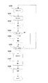
次に、図5のフローチャートを用いて、本実施例の撮像装置の動作について説明する。まず、ステップS300において、撮像装置1のメインスイッチ19がオンされた等の要因によりカメラの電源が入ると、CPU117は、ステップS301から動作を開始する。
Next, the operation of the imaging apparatus of the present embodiment will be described using the flowchart of FIG. First, in step S300, when the camera is turned on due to factors such as the
ステップS301においては、レリーズボタン7の第1ストローク操作が行われ、レリーズスイッチSW1(126)がオンすると、ステップS302において、測光回路124を動作させて被写体からの反射光を取り込み、A/D変換して測光情報を得る。そして、露出条件(絞り,シャッタースピード)の演算を行なう。
In step S301, when the first stroke operation of the
次に、ステップS303にて、焦点検出モードがオートフォーカスモード(AF)かマニュアルフォーカスモード(MF)かを判別し、MFの場合はステップS305へ進み、AFの場合はステップS304へ進む。 Next, in step S303, it is determined whether the focus detection mode is the auto focus mode (AF) or the manual focus mode (MF). If MF, the process proceeds to step S305. If AF, the process proceeds to step S304.
ステップS304では、焦点検出回路125を用いて各焦点検出領域でのフォーカス情報を算出する。そして、これらのフォーカス情報を基に所定のアルゴリズムでデフォーカス量算出演算を行う。さらに、CPU117が自動的に又は撮影者が測距点選択ボタン4,6の操作により選択された焦点検出領域でのデフォーカス量に基づきフォーカスレンズの駆動量を演算する。そして、該駆動量をレンズ駆動回路122へ通信し、フォーカスレンズを駆動させ、合焦を得る。
In step S304, focus information in each focus detection region is calculated using the
そして、次のステップS305において、カメラの状態がレリーズを許可して良い状態か否かの判別を行う。例えば、AFモードが「ワンショットモード」である場合は、上記ステップS304での焦点検出結果が合焦ならばレリーズは許可され、ステップS306へ進む。合焦でない場合はステップS300に戻る。 Then, in the next step S305, it is determined whether or not the camera is in a state that permits release. For example, when the AF mode is “one-shot mode”, release is permitted if the focus detection result in step S304 is in focus, and the process proceeds to step S306. If not in focus, the process returns to step S300.
上記の様にステップS300に戻った後は、必要に応じてモード等の設定を行い、ステップS301へと進む。そして、レリーズボタン7の第1ストローク操作が行われてレリーズスイッチSW1(126)がオンすると、再び測光,MF/AF判別,焦点検出を行ない(S302→S303→S304)、再度カメラの状態がレリーズを許可して良い状態か否かの判別を行う(S305)。
After returning to step S300 as described above, a mode or the like is set as necessary, and the process proceeds to step S301. When the first stroke operation of the
次のステップS306において、レリーズスイッチSW2(127)がオンすると、撮像(画像データの取得および記録)動作を行うためにステップS307に進む。 In next step S306, when the release switch SW2 (127) is turned on, the process proceeds to step S307 in order to perform an imaging (acquisition and recording of image data) operation.
ステップS307では、ステップS302にて算出された露出条件(絞り,シャッタースピード)にて固体撮像素子100に露光を行なう。そして、ステップS308に進み、固体撮像素子100に撮像された画像信号を所定の形態の画像データに変換する。ここで、「通常記録モード」が設定されているときは、記録媒体であるメモリカード114,116のどちらか一方に画像データを記録する。「同時記録モード」が設定されているときは、画像データとともに、同時記録識別情報(すなわち、同時記録モードで撮像された画像データであることを示す情報)を両方のメモリカード114,116に記録し、撮像動作を終了する。
In step S307, the solid-
なお、同時記録識別情報は、メモリカード114,116のうちいずれか一方にのみ記録してもよい。
Note that the simultaneous recording identification information may be recorded only on one of the
次に、図6のフローチャートを用いて、図5に示した記録動作(ステップS308)についてさらに詳しく説明する。 Next, the recording operation (step S308) shown in FIG. 5 will be described in more detail using the flowchart of FIG.
図6において、ステップS310では、CPU117は、記録モードが「同時記録モード」か「通常記録モード」かを判別する。「通常記録モード」であればステップS313へ進み、事前に撮影者によりメモリスロット選択ボタン21およびサブ電子ダイヤル17によって選択されたメモリスロットに装着されているメモリカードに、取得した画像データを記録する。
また、「同時記録モード」であればステップS311へ進む。
In FIG. 6, in step S310, the
If it is “simultaneous recording mode”, the process advances to step S311.
ステップS311では、メモリスロット1(113)およびメモリスロット2(115)にそれぞれメモリカード1(114)およびメモリカード2(116)が装着されているか否かを判別し、両方装着されていればステップS312へ進み、どちらか一方しか装着されていないときはステップS314へ進む。 In step S311, it is determined whether or not the memory card 1 (114) and the memory card 2 (116) are installed in the memory slot 1 (113) and the memory slot 2 (115), respectively. The process proceeds to S312 and if only one of them is attached, the process proceeds to Step S314.
ステップS312では、ステップS307にて取得された画像データと共に、同時記録識別情報(識別データ)を両方のメモリカードもしくは一方のメモリカードに記録する。 In step S312, the simultaneous recording identification information (identification data) is recorded on both the memory cards or one of the memory cards together with the image data acquired in step S307.
ステップS314では、「同時記録モード」が選択されているにもかかわらずメモリカードが2枚装着されていない旨の警告表示をLCD20を通じて行う。但し、同様の警告を、外部表示器12や他の警告ランプによって行ってもよい。また、警告の方法として、視覚による警告のみでなく、聴覚や振動による警告でもよい。
In step S314, a warning display to the effect that two memory cards are not installed even though the “simultaneous recording mode” is selected is performed through the
次に、図7のフローチャートを用いて、メモリカードに記録された画像データの再生動作について説明する。 Next, the reproduction operation of the image data recorded on the memory card will be described using the flowchart of FIG.
まずステップS400において、メインスイッチがオンされた等の要因によりカメラの電源が入った状態であり、この状態からディスプレイボタン24が押されると、CPU117は、まずステップS401で、画像再生モードの設定を行う。ここで選択ボタン23が押されるとステップS402の設定モードへ、ディスプレイボタン24が再度押された場合はステップS403へとそれぞれ進む。
First, in step S400, the camera is turned on due to factors such as the main switch being turned on. When the
ステップS402では、LCD20への表示を制御する画像再生モードを設定する。画像再生モードには、1枚表示する「シングル再生モード」と、複数枚同時に表示する「マルチ再生モード」と、画像データとその画像データの輝度分布を表すヒストグラムとを同時に表示する「ヒストグラムモード」の3つがある。撮影者が選択ボタン23を押しながらサブ電子ダイヤル17を回転させて希望の画像再生モードを選択し、選択ボタン23を離すと、該選択された画像再生モードが設定される。そして、ステップS403へ進む。なお、画像再生モードの初期設定は、「シングル再生モード」となっている。
In step S402, an image reproduction mode for controlling display on the
ステップS403では、画像データがメモリカード1(114)またはメモリカード2(116)に存在するか否かを判断し、画像データがメモリカード1(114)またはメモリカード2(116)に存在する場合はステップS405へ進む。画像データがメモリカード1(114)およびメモリカード2(116)のいずれにも存在しない場合は、ステップS404へ進み、LCD20にその旨を示す警告情報を表示させる。
In step S403, it is determined whether the image data exists in the memory card 1 (114) or the memory card 2 (116), and the image data exists in the memory card 1 (114) or the memory card 2 (116). Advances to step S405. If the image data does not exist in either the memory card 1 (114) or the memory card 2 (116), the process proceeds to step S404, and warning information indicating that fact is displayed on the
ステップS405では、メモリカード1(114)またはメモリカード2(116)のどちらか一方の画像を表示する。ここで、表示する画像データに対して同時記録識別情報が記録されている場合は、後述する同時記録モードマークも表示させる。これにより、再生画像を見ながら同時にその画像が「同時記録モード」で撮影された画像であること、つまりはバックアップ画像データが存在することを認識することができる。 In step S405, the image of either memory card 1 (114) or memory card 2 (116) is displayed. Here, when the simultaneous recording identification information is recorded for the image data to be displayed, a simultaneous recording mode mark described later is also displayed. As a result, it is possible to recognize that the reproduced image is an image taken in the “simultaneous recording mode”, that is, that backup image data exists.
なお、メモリカード1(114)およびメモリカード2(116)の双方が装着されている場合においては、同時記録識別情報が記録されているメモリカード側の画像データを優先して表示するようにしてもよい。以上で画像の再生動作が終了する。 When both the memory card 1 (114) and the memory card 2 (116) are mounted, the image data on the memory card side on which the simultaneous recording identification information is recorded is displayed with priority. Also good. This completes the image playback operation.
図8には、前述した各画像再生モードにおけるLCD20への表示例を示している。図8(a)は「シングル再生モード」にて、図8(b)は「マルチ再生モード」にて、図8(c)は「ヒストグラムモード」にて再生したときの表示例である。
FIG. 8 shows a display example on the
図8(a)〜(c)において、201はLCD20に再生された画像であり、202はシャッタースピード、203は絞り値を表している。図8(a)〜(c)では、再生画像がシャッタースピード1/250秒、絞り値F5.6にて撮影された画像であることを示している。
8A to 8C, 201 denotes an image reproduced on the
204は同時記録モードマークであり、再生画像が「同時記録モード」にて撮影された画像か否かを識別するためのマークである。図8(a)〜(c)ではいずれも再生画像が「同時記録モード」にて撮影された画像であることを示している。なお、「通常記録モード」にて撮影された画像を再生したときは、同時記録モードマーク204は表示されない。したがって、当該画像データにはバックアップが存在しない可能性があることを使用者は認識することができる。
205は記録画質モードマークであり、再生画像の記録時の画素数と圧縮率とを表している。図8(a)〜(c)では、高画素数(F)で低圧縮率(L)にて記録された画像であることを示している。
図8(c)において、206は撮影時の撮影モードを示すマーク、207は測光モードを示すマーク、208はISO感度を示すマークである。図8(c)では、絞り優先モード、スポット測光モード、ISO感度200にて撮影された画像であることを示している。
In FIG. 8C,
209はホワイトバランスモードを示すマークであり、図8(c)では、撮像出力信号からカメラが自動的にホワイトバランスを設定するオートホワイトバランス(AWB)にて画像処理された画像であることを示している。
210のマークは、撮影年月日・撮影時刻を表し、211のマークは再生画像のファイル番号を表している。
A
212のマークは再生画像の明るさの分布を示すヒストグラムである。ヒストグラムとは、横軸に明るさ、縦軸にその明るさの画素数を積み上げたグラフである。ヒストグラム212の左に寄るほど暗い画素になり、右に寄るほど明るい画素になる。このヒストグラムを見ることにより、撮影した画像がどの程度の明るさか判断することができる。暗いほうに偏っているようであれば露出補正をプラス補正し、明るいほうに偏っているようであればマイナス補正して再度撮影することで、より良質な画像が得られる。
A
なお、本実施例では、「同時記録モード」にて撮影されたか否かの識別の方法として識別マークを表示するようにしているが、表示されている画像の枠の色を変えることで識別してもよい。 In this embodiment, an identification mark is displayed as a method for identifying whether or not the image is taken in the “simultaneous recording mode”. However, the identification mark is identified by changing the color of the frame of the displayed image. May be.
以上の構成により、再生画像が「同時記録モード」にて撮影されたか否かを容易に識別でき、バックアップ画像の有無を認識することができる。また、再生画像の枠の色を、「同時記録モード」にて撮影した画像と、「通常記録モード」にて撮影した画像とで変えるようにしているので、マルチ再生モードのように複数画像が同時に表示されるようなときに、「同時記録モード」で撮影された画像か否かを容易に識別できる。 With the above configuration, it is possible to easily identify whether or not the reproduced image is shot in the “simultaneous recording mode”, and it is possible to recognize the presence or absence of the backup image. In addition, since the frame color of the playback image is changed between the image shot in the “simultaneous recording mode” and the image shot in the “normal recording mode”, multiple images can be displayed as in the multi playback mode. When the images are displayed at the same time, it is possible to easily identify whether the images are taken in the “simultaneous recording mode”.
図9には、本発明の実施例2における撮像装置を示すブロック図である。なお、図4と同一又は同様の構成要素には同一符号を付して説明に代える。
FIG. 9 is a block diagram illustrating an imaging apparatus according to
本実施例では、実施例1の構成に加えて、複数のメモリカード間で記録画像データを転送してダビング(複写)を行うダビング制御回路160およびダビング操作部161を有している。
In the present embodiment, in addition to the configuration of the first embodiment, a dubbing control circuit 160 and a
ダビング操作部161におけるスイッチ操作に応じた指示により、ダビング制御回路160は、一方のメモリカードから画像データを読み出し、他方のメモリカードへこれを書き込む。これにより、バックアップ画像データが作成されることになる。
In response to an instruction according to the switch operation in the
図10には、ダビング動作のシーケンスフローチャートを示している。ステップS501では、ダビング操作部161においてダビングを開始させるスイッチが操作されたか否かを判別する。なお、この時点で、ダビング元のメモリカードに記録された画像データの中から、ダビングしたい画像データが使用者により選択され、LCD20に表示されているものとする。スイッチが操作されたときはステップS502に進む。
FIG. 10 shows a sequence flowchart of the dubbing operation. In step S501, it is determined whether or not the
ステップS502では、ダビング操作部161において予め使用者により設定されたダビング元のメモリカード(スロット)とダビング先のメモリカード(スロット)の設定情報を読み込む。ダビング元→ダビング先が、メモリカード1(114)→メモリカード2(116)の場合はステップS503に、メモリカード2(116)→メモリカード1(114)の場合はステップS504にそれぞれ進む。
In step S502, setting information of a dubbing source memory card (slot) and a dubbing destination memory card (slot) preset by the user in the
ステップS503では、メモリカード1(114)から、選択された画像データをメモリカード2(116)に転送する。これにより、該選択された画像データと同一の画像データがメモリカード2(116)に複写される。そして、ステップS505に進む。 In step S503, the selected image data is transferred from the memory card 1 (114) to the memory card 2 (116). As a result, the same image data as the selected image data is copied to the memory card 2 (116). Then, the process proceeds to step S505.
ステップS504では、メモリカード2(116)から、選択された画像データをメモリカード1(114)に転送する。これにより、該選択された画像データと同一の画像データがメモリカード1(114)に複写される。そして、ステップS505に進む。 In step S504, the selected image data is transferred from the memory card 2 (116) to the memory card 1 (114). As a result, the same image data as the selected image data is copied to the memory card 1 (114). Then, the process proceeds to step S505.
ステップS505では、ダビングされた画像データがダビングされたものであることを示すダビング識別情報を、ダビング元およびダビング先のメモリカードのうち両方又は一方に記録する。そして、本フローを終了する。 In step S505, dubbing identification information indicating that the dubbed image data has been dubbed is recorded on both or one of the dubbing source and dubbing destination memory cards. Then, this flow ends.
以上説明したダビング処理が行われた画像データをLCD20上で表示する際には、CPU117は、図7に示したフローチャートと同様なフローチャートにしたがって動作する。すなわち、まず画像再生モードの設定を行い(ステップS401,402参照)、各メモリカードに再生すべき画像データが存在するか否かを判別する(ステップS403参照)。
When displaying the image data subjected to the dubbing process described above on the
再生すべき画像データが存在するときは、その画像データをメモリカードから読み出して、設定された画像再生モードに応じてLCD20に表示する(ステップS405参照)。このとき、再生画像データに対してダビング識別情報が存在するか否かを判別し、前述した図8(b)に示す同時記録モードマーク204と同様に、ダビングマーク(図示せず)をLCD20に表示する。
When there is image data to be reproduced, the image data is read from the memory card and displayed on the
これにより、再生した画像がダビング処理を行った画像か否かが容易に識別でき、バックアップ画像の有無を認識することができる。 Thereby, it is possible to easily identify whether the reproduced image is a dubbed image and to recognize the presence or absence of a backup image.
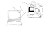
図12には、本発明の実施例3における撮像装置1とその外部に設けられた外部記録装置としてのパーソナルコンピュータ40とをケーブル41を介して接続した状態を示している。
FIG. 12 shows a state in which the imaging apparatus 1 according to the third embodiment of the present invention and a
また、図11には、本実施例の撮像装置の一側面の構成を示す図である。図11において、36はシンクロ端子であり、シンクロコード付きの外部ストロボユニット(図示せず)と接続することができる。37はリモコン端子であり、コード付きのリモコンユニット(図示せず)と接続することができる。
FIG. 11 is a diagram illustrating a configuration of one side surface of the imaging apparatus according to the present embodiment. In FIG. 11,
38はデジタル端子であり、パーソナルコンピュータ40に繋がるケーブル41を接続することができる。これらの接続端子は、撮像装置1のグリップ部とは反対側に配置されている。
図12において、撮像装置1にて「同時記録モード」が設定されている場合、撮像装置1にて取得された画像データは、撮像装置1に装着されたメモリカードとパーソナルコンピュータ40内のハードディスク(記録媒体)に、実施例1で説明した同時記録識別情報とともに転送される。これにより、画像データのバックアップデータが作成され、記録される。 In FIG. 12, when the “simultaneous recording mode” is set in the image capturing apparatus 1, the image data acquired by the image capturing apparatus 1 is stored in a memory card mounted on the image capturing apparatus 1 and a hard disk in the personal computer 40 ( To the recording medium) together with the simultaneous recording identification information described in the first embodiment. Thereby, backup data of the image data is created and recorded.
また、撮像装置1にてダビング処理の実行が選択された場合、撮像装置1に装着されたメモリカードおよびパーソナルコンピュータ40内のハードディスクのうち一方から他方に画像データがダビングされる。またこれとともに、実施例2で説明したダビング識別情報が、メモリカードおよびハードディスクに記録される。
Further, when execution of the dubbing process is selected in the imaging apparatus 1, image data is dubbed from one to the other of the memory card attached to the imaging apparatus 1 and the hard disk in the
これらより、画像データのバックアップデータが作成されて記録されるとともに、該画像データを表示したときには、その画像が「同時記録モード」で撮影されたもの若しくはダビングされたものであることを示す表示も行われる。 As a result, backup data of the image data is created and recorded, and when the image data is displayed, a display indicating that the image is taken or dubbed in the “simultaneous recording mode” is also displayed. Done.
なお、本実施例では、ケーブル41を介して撮像装置1とコンピュータ40間で通信を行う場合について説明したが、光通信や電波通信等による無線通信を行ってもよい。また、撮像装置とパーソナルコンピュータ以外の外部記録装置とを接続して、画像データや情報の通信を行うようにしてもよい。
In the present embodiment, the case where communication is performed between the imaging apparatus 1 and the
さらに、上記各実施例では、撮像装置について説明したが、本発明は、撮像装置以外の電子機器であって、複数の記録媒体に対するデータ記録やダビング処理を行えるものの全てに適用することができる。 Further, in each of the above embodiments, the imaging apparatus has been described. However, the present invention can be applied to all electronic apparatuses other than the imaging apparatus that can perform data recording and dubbing processing on a plurality of recording media.
1 撮像装置
7 レリーズボタン
8 メイン電子ダイヤル
12 外部表示器
17 サブ電子ダイヤル
20 LCD
21 メモリスロット選択ボタン
29 メモリスロットカバー
30 アクセスランプ
31 第1のメモリスロット
32 第2のメモリスロット
40 ノート型パーソナルコンピュータ
38 デジタル端子
41 ケーブル
100 固体撮像素子
114 メモリカード1
116 メモリカード2
119 温度センサ
160 ダビング制御回路
161 ダビング操作部
1
DESCRIPTION OF
116
119 Temperature sensor 160
Claims (6)
画像データを取得する画像データ取得手段と、
前記取得した画像データを前記第1の媒体接続手段に接続された第1の記録媒体および前記第2の媒体接続手段に接続された第2の記録媒体のうち一方に記録する第1の記録処理と、前記取得した画像データを前記第1および第2の記録媒体の双方に記録する第2の記録処理とを行う記録手段とを有し、
前記記録手段は、前記第2の記録処理を行うときは、前記第1および第2の記録媒体のうち少なくとも一方に、前記取得した画像データとともに該画像データが前記第2の記録処理で記録されたことを示す情報を記録することを特徴とする電子機器。 First and second medium connecting means each capable of connecting a recording medium;
Image data acquisition means for acquiring image data;
A first recording process for recording the acquired image data on one of a first recording medium connected to the first medium connecting means and a second recording medium connected to the second medium connecting means; And a recording means for performing a second recording process for recording the acquired image data on both the first and second recording media,
When the recording means performs the second recording process, the image data is recorded in the second recording process together with the acquired image data on at least one of the first and second recording media. An electronic device characterized by recording information indicating that
該出力手段は、前記記録された画像データとともに前記情報を出力することを特徴とする請求項1に記載の電子機器。 Output means for reproducing and outputting the image data recorded on the first and second recording media,
The electronic apparatus according to claim 1, wherein the output unit outputs the information together with the recorded image data.
被写体像を光電変換する撮像素子を有し、
前記画像データ取得手段は、前記撮像素子を用いて画像データを取得することを特徴とする撮像装置。 The electronic device according to claim 1 or 2,
An image sensor that photoelectrically converts a subject image;
The image data acquisition means acquires image data using the image sensor.
前記第1の媒体接続手段に接続された第1の記録媒体と前記第2の媒体接続手段に接続された第2の記録媒体のうち一方に記録された画像データを他方にダビングするダビング動作が可能な記録手段とを有し、
前記記録手段は、前記ダビング動作を行うときは、前記第1および第2の記録媒体のうち少なくとも一方に、前記画像データがダビングされたものであることを示す情報を記録することを特徴とする電子機器。 First and second medium connecting means each capable of connecting a recording medium;
A dubbing operation for dubbing image data recorded on one of the first recording medium connected to the first medium connecting means and the second recording medium connected to the second medium connecting means to the other; Possible recording means,
When performing the dubbing operation, the recording unit records information indicating that the image data is dubbed on at least one of the first and second recording media. Electronics.
該出力手段は、前記記録された画像データとともに前記情報を出力することを特徴とする請求項3に記載の電子機器。 Output means for reproducing and outputting the image data recorded on the first and second recording media,
The electronic device according to claim 3, wherein the output unit outputs the information together with the recorded image data.
被写体像を光電変換する撮像素子を有し、
前記記録手段は、前記撮像素子を用いて得られた画像データを前記第1および第2の記録媒体のうち少なくとも一方に記録することを特徴とする撮像装置。
The electronic device according to claim 4 or 5,
An image sensor that photoelectrically converts a subject image;
The image recording apparatus, wherein the recording unit records image data obtained using the image sensor on at least one of the first and second recording media.
Priority Applications (1)
| Application Number | Priority Date | Filing Date | Title |
|---|---|---|---|
| JP2003417173A JP2005176265A (en) | 2003-12-15 | 2003-12-15 | Electronic apparatus and image pickup unit |
Applications Claiming Priority (1)
| Application Number | Priority Date | Filing Date | Title |
|---|---|---|---|
| JP2003417173A JP2005176265A (en) | 2003-12-15 | 2003-12-15 | Electronic apparatus and image pickup unit |
Publications (2)
| Publication Number | Publication Date |
|---|---|
| JP2005176265A true JP2005176265A (en) | 2005-06-30 |
| JP2005176265A5 JP2005176265A5 (en) | 2007-02-08 |
Family
ID=34736165
Family Applications (1)
| Application Number | Title | Priority Date | Filing Date |
|---|---|---|---|
| JP2003417173A Pending JP2005176265A (en) | 2003-12-15 | 2003-12-15 | Electronic apparatus and image pickup unit |
Country Status (1)
| Country | Link |
|---|---|
| JP (1) | JP2005176265A (en) |
Cited By (4)
| Publication number | Priority date | Publication date | Assignee | Title |
|---|---|---|---|---|
| JP2011010179A (en) * | 2009-06-29 | 2011-01-13 | Nikon Corp | Camera |
| JP2011066823A (en) * | 2009-09-18 | 2011-03-31 | Canon Inc | Imaging apparatus, control method thereof and program |
| JP2012049630A (en) * | 2010-08-24 | 2012-03-08 | Canon Inc | Recording device and recording method |
| US9407894B2 (en) | 2005-03-31 | 2016-08-02 | Hitachi Maxell, Ltd. | Information recording/play-backing apparatus |
-
2003
- 2003-12-15 JP JP2003417173A patent/JP2005176265A/en active Pending
Cited By (4)
| Publication number | Priority date | Publication date | Assignee | Title |
|---|---|---|---|---|
| US9407894B2 (en) | 2005-03-31 | 2016-08-02 | Hitachi Maxell, Ltd. | Information recording/play-backing apparatus |
| JP2011010179A (en) * | 2009-06-29 | 2011-01-13 | Nikon Corp | Camera |
| JP2011066823A (en) * | 2009-09-18 | 2011-03-31 | Canon Inc | Imaging apparatus, control method thereof and program |
| JP2012049630A (en) * | 2010-08-24 | 2012-03-08 | Canon Inc | Recording device and recording method |
Similar Documents
| Publication | Publication Date | Title |
|---|---|---|
| US7706674B2 (en) | Device and method for controlling flash | |
| US8670064B2 (en) | Image capturing apparatus and control method therefor | |
| US20080193121A1 (en) | Imaging apparatus | |
| JP4250436B2 (en) | Display control device | |
| JP2006313978A (en) | Imaging apparatus, control method, and computer program | |
| JP4266801B2 (en) | Electronic equipment and control program | |
| JP2006253810A (en) | Image pickup device | |
| JP2004120225A (en) | Digital camera | |
| JP2004032524A (en) | Digital camera | |
| JP2005176265A (en) | Electronic apparatus and image pickup unit | |
| JP2005292740A (en) | Electronic camera | |
| JP4393177B2 (en) | Imaging apparatus and imaging method | |
| JP4948011B2 (en) | Imaging apparatus, control method therefor, computer program, and storage medium | |
| JP4838644B2 (en) | Imaging apparatus, control method thereof, and program | |
| JP4310181B2 (en) | Electronics | |
| JP3913046B2 (en) | Imaging device | |
| JP4401974B2 (en) | Imaging apparatus and control method thereof | |
| JP2002135636A (en) | Electronic camera | |
| JP5178438B2 (en) | IMAGING DEVICE, IMAGING DEVICE CONTROL METHOD, AND PROGRAM | |
| JP5555103B2 (en) | Image recording apparatus, method and program | |
| JP2005184609A (en) | Electronic camera | |
| JP4298491B2 (en) | Imaging device | |
| JP2003189160A (en) | Digital camera | |
| JP2007101860A (en) | Imaging apparatus | |
| JP2007214938A (en) | Digital camera |
Legal Events
| Date | Code | Title | Description |
|---|---|---|---|
| A521 | Request for written amendment filed |
Free format text: JAPANESE INTERMEDIATE CODE: A523 Effective date: 20061212 |
|
| A621 | Written request for application examination |
Free format text: JAPANESE INTERMEDIATE CODE: A621 Effective date: 20061212 |
|
| A131 | Notification of reasons for refusal |
Free format text: JAPANESE INTERMEDIATE CODE: A131 Effective date: 20080318 |
|
| A02 | Decision of refusal |
Free format text: JAPANESE INTERMEDIATE CODE: A02 Effective date: 20080729 |