JP2005173291A - Image display system and image display method - Google Patents
Image display system and image display method Download PDFInfo
- Publication number
- JP2005173291A JP2005173291A JP2003414192A JP2003414192A JP2005173291A JP 2005173291 A JP2005173291 A JP 2005173291A JP 2003414192 A JP2003414192 A JP 2003414192A JP 2003414192 A JP2003414192 A JP 2003414192A JP 2005173291 A JP2005173291 A JP 2005173291A
- Authority
- JP
- Japan
- Prior art keywords
- image display
- image
- display device
- display
- display devices
- Prior art date
- Legal status (The legal status is an assumption and is not a legal conclusion. Google has not performed a legal analysis and makes no representation as to the accuracy of the status listed.)
- Pending
Links
Images


Landscapes
- Digital Computer Display Output (AREA)
- Control Of Indicators Other Than Cathode Ray Tubes (AREA)
- Controls And Circuits For Display Device (AREA)
- User Interface Of Digital Computer (AREA)
Abstract
【課題】 複数の画像表示装置がその位置に対応して、最適に画像を表示することができ、これによって、複数の画像表示装置を有効に活用することができ、また、画像表示装置の連携によって、ユーザによる表示切替が容易である画像表示システムを提供することを目的とする。
【解決手段】 互いに異なる識別番号を具備し、無線通信機能を具備する複数の画像表示装置と、上記複数の画像表示装置のそれぞれの位置を検出し、上記画像表示装置の位置情報に応じた表示画像を、対応する画像表示装置に無線送信する画像制御装置とを有し、上記画像表示装置は、自己の位置情報に対応する表示画像を表示することを特徴とする画像表示システムである。
【選択図】 図1
PROBLEM TO BE SOLVED: To optimally display an image corresponding to the position of a plurality of image display devices, thereby enabling effective use of the plurality of image display devices and cooperation of the image display devices. Thus, an object of the present invention is to provide an image display system in which display switching by a user is easy.
A plurality of image display devices having different identification numbers and having a wireless communication function, and positions of the plurality of image display devices are detected, and display according to position information of the image display device is performed. An image control device that wirelessly transmits an image to a corresponding image display device, and the image display device displays a display image corresponding to its own position information.
[Selection] Figure 1
Description
本発明は、複数のディスプレイへの表示内容が相互に連携しているマルチディスプレイシステムに画像表示させるシステムおよび画像表示方法に関する。
The present invention relates to a system and an image display method for displaying an image on a multi-display system in which display contents on a plurality of displays cooperate with each other.
近年、表示装置の大画面化の要求が益々高まっており、マルチメディアディスプレイのニーズが増え、複数のディスプレイへの画像表示の機会が増える傾向にある。 In recent years, there has been an increasing demand for display devices with a larger screen, the need for multimedia displays has increased, and there is a tendency to increase the chances of displaying images on a plurality of displays.
複数のディスプレイに画像を表示する方法として、複数のディスプレイを縦横に整列することによって、1つの大画面ディスプレイを構成するタイリング・ディスプレイがあり、小画面サイズのディスプレイを並べることによって、大画面表示を実現することができる。また、各ディスプレイに独立したウインドウ表示内容を割り当て、異なるウインドウ情報を表示するマルチウインドウ型ディスプレイも有効である。 As a method of displaying images on multiple displays, there is a tiling display that constitutes one large screen display by aligning the multiple displays vertically and horizontally, and a large screen display by arranging small display sizes. Can be realized. A multi-window type display that assigns independent window display contents to each display and displays different window information is also effective.
また、携帯電話や携帯端末等の普及によって、ユビキタスなディスプレイが求められ、軽量薄型、フレキシブル、頑丈なディスプレイが開発されつつある。たとえば、ペーパーディスプレイ、フレキシブルディスプレイ等という類のディスプレイである。 In addition, with the spread of mobile phones and mobile terminals, ubiquitous displays are required, and lightweight, thin, flexible, and sturdy displays are being developed. For example, a display such as a paper display or a flexible display.
ペーパーディスプレイには、電気泳動型ディスプレイ、トナーディスプレイ、ツイスティッドボール・ディスプレイ、反射型のメモリ性のある液晶ディスプレイ等がある。フレキシブルディスプレイには、プラスチック基板上に形成した液晶ディスプレイ、有機ELディスプレイ等である。 Examples of the paper display include an electrophoretic display, a toner display, a twisted ball display, and a reflective liquid crystal display with a memory property. Examples of the flexible display include a liquid crystal display and an organic EL display formed on a plastic substrate.
このようなペーパーディスプレイやフレキシブルディスプレイ等は、軽量薄型でフレキシブルであるので、複数枚を同時に使用することが想定される。特に、メモリ性のあるペーパーディスプレイの場合、紙を扱う感覚で、複数枚を平面上に広げて用いる機会が多いと予測される。 Since such a paper display, a flexible display, and the like are lightweight, thin, and flexible, it is assumed that a plurality of sheets are used simultaneously. In particular, in the case of a paper display having a memory property, it is expected that there are many opportunities to use a plurality of sheets spread on a plane as if handling paper.
従来、複数の画像表示装置を用いた画像表示システムとしては、コンピュータ等の画像制御装置に、ディスプレイ・ケーブルによって、複数の画像表示装置が直接接続されている画像表示システムの例がある。この場合、各ディスプレイは、グラフィックス・ボードによって、ポート番号が割り当てられ、各ポート番号のディスプレイに、予め決められた各画像を伝送することによって、複数の画像表示を実現する。 Conventionally, as an image display system using a plurality of image display apparatuses, there is an example of an image display system in which a plurality of image display apparatuses are directly connected to an image control apparatus such as a computer by a display cable. In this case, each display is assigned a port number by the graphics board, and a plurality of images are displayed by transmitting each predetermined image to the display of each port number.
また、無線によるデータ通信機能を有したペーパーディスプレイ装置に関して、ペーパーディスプレイ装置の優れた可撓性、収納性を有し、携帯端末よりも大きい大画面表示を可能にする(たとえば、特許文献1参照)。また、軽量、大画面、折り曲げに強いという特徴から情報ヒューマンインタフェースとして活用される。 Further, regarding a paper display device having a wireless data communication function, the paper display device has excellent flexibility and storage property, and enables a larger screen display than a portable terminal (for example, see Patent Document 1). ). It is also used as an information human interface because of its light weight, large screen, and resistance to bending.
また、タイリング可能なディスプレイシステムとして、データを転送可能なディスプレイ(たとえば、特許文献2参照)が、複数、互いに接触することによって、データ転送を行ない、タイリング表示を可能としている。
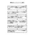
しかし、現在の画像表示装置を用いて、複数枚の画像表示を行なわせる場合、以下のような問題がある。
1.ディスプレイ・ケーブルによって結線されている従来の画像表示システムでは、各画像表示装置の場所を自由に変えて用いることが困難であるという問題がある。
2.複数枚の画像表示装置の場所を変えて用いる場合、それらに表示される表示画像は、予め設定されているので、画像表示装置の位置に合わせて見やすいように表示することができないという問題がある。
3.複数枚の画像表示装置を縦横に並べて、あたかも1枚の大画面ディスプレイのように用いる場合、複数の画像表示装置への表示画像を設定、調整することが、時間、手間を必要とし、また、配置を換えた場合、再度調整が必要であるという問題がある。
However, when displaying a plurality of images using the current image display device, there are the following problems.
1. In the conventional image display system connected by the display cable, there is a problem that it is difficult to freely change the location of each image display device.
2. When using a plurality of image display devices at different locations, the display images displayed on the image display devices are set in advance, so that there is a problem that the images cannot be displayed so as to be easy to see according to the position of the image display device. .
3. When a plurality of image display devices are arranged vertically and horizontally and used like a single large screen display, setting and adjusting the display image on the plurality of image display devices requires time and effort, When the arrangement is changed, there is a problem that adjustment is necessary again.
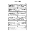
本発明は、通信機能を具備する複数の画像表示装置と、上記複数の画像表示装置のそれぞれの位置を検出し、上記画像表示装置の位置情報に応じた表示画像を、対応する画像表示装置に送信する画像制御装置とを有し、上記画像表示装置は、自己の位置情報に対応する表示画像を表示することを特徴とする画像表示システムである。 The present invention detects a position of each of a plurality of image display devices having a communication function and the plurality of image display devices, and displays a display image corresponding to the position information of the image display device as a corresponding image display device. And an image control device that transmits the image. The image display device displays a display image corresponding to its own position information.
また、本発明は、複数の画像表示装置に画像を表示させるための画像表示方法において、上記複数の画像表示装置のそれぞれの位置を検出し、該検出した位置に応じた表示画像を各画像表示装置において表示することを特徴とする画像表示方法である。
According to another aspect of the present invention, there is provided an image display method for displaying an image on a plurality of image display devices, wherein each position of the plurality of image display devices is detected, and a display image corresponding to the detected position is displayed on each image. An image display method characterized by displaying on an apparatus.
本発明によれば、複数の画像表示装置がその位置に対応して、最適に画像を表示することができ、これによって、複数の画像表示装置を有効に活用することができるという効果を奏する。また、本発明によれば、画像表示装置の連携によって、ユーザによる表示切替が容易であるという効果を奏する。
According to the present invention, a plurality of image display devices can optimally display an image corresponding to the position, thereby producing an effect that a plurality of image display devices can be effectively utilized. Further, according to the present invention, there is an effect that display switching by the user is easy by cooperation of the image display device.
発明を実施するための最良の形態は、次の実施例である。 The best mode for carrying out the invention is the following embodiment.
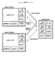
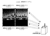
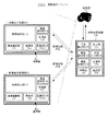
図1は、本発明の実施例1である画像表示システム100を示す構成図である。
FIG. 1 is a configuration diagram illustrating an image display system 100 that is
画像表示システム100は、画像表示装置DP1とDP2と、画像制御装置30とを有する。
The image display system 100 includes image display devices DP1 and DP2 and an
画像表示装置DP1は、TFT駆動液晶ディスプレイによって構成されている画像表示部11と、画像駆動部12と、処理部13と、無線通信部14と、電源部15と、記憶部16と、位置検出部17とを有し、その位置情報に対応する表示画像を表示する。
The image display device DP1 includes an
画像駆動部12は、画像表示部11の駆動回路部であり、走査線駆動回路、信号線駆動回路、DA変換回路、タイミングコントロール回路、グラフィックス・コントローラ・インタフェース等を有する。
The
処理部13は、表示画像の伸張、映像信号の受信等を行なう処理部であり、また、低消費電力を維持しながら、位置検出を制御し、無線通信によって取り込まれた画像信号を、画像表示部によって表示することを、制御処理する。
The
無線通信部14は、画像制御装置30との間のデータの送受信を行なう無線通信部である。
The
電源部15は、画像表示、無線通信、位置検出、各種処理にとって必要な電力を管理し、供給する。 The power supply unit 15 manages and supplies power necessary for image display, wireless communication, position detection, and various processes.
記憶部16は、画像表示装置を区別するための識別子ID1他を内蔵する記憶部であり、また、位置情報、表示画像等を一時的に記憶する場合もある。識別子ID1は、画像表示装置DP1に割り振られたID情報であり、位置検出時、通信時のデータの受渡し時に、画像表示装置DP1を識別するために用いる。 The storage unit 16 is a storage unit that contains an identifier ID1 and the like for distinguishing image display devices, and may temporarily store position information, a display image, and the like. The identifier ID1 is ID information assigned to the image display device DP1, and is used to identify the image display device DP1 when detecting the position and when transferring data during communication.
位置検出部17は、光反射器によって構成されている。 The position detection unit 17 is configured by a light reflector.
画像表示装置DP2は、画像表示装置DP1と同様に、画像表示部21と、TFT−LCD駆動用の画像駆動部22と、表示画像の伸張、映像信号の受信等を行なう処理部23と、画像制御装置30との間のデータの送受信を行なう無線通信部24と、電源部25と、画像表示装置を区別するための識別子ID2他を内蔵する記憶部26と、光反射器からなる位置検出部27とを有し、画像表示装置DP2は、その位置情報に対応する表示画像を表示する。
Similar to the image display device DP1, the image display device DP2 includes an image display unit 21, an image drive unit 22 for driving the TFT-LCD, a processing unit 23 that performs display image expansion, video signal reception, and the like. A wireless communication unit 24 that transmits and receives data to and from the
なお、識別子ID2は、画像表示装置DP2に割り振られたID情報であり、位置検出時、通信時のデータの受渡し時に、画像表示装置DP2を識別するために用いる。 The identifier ID2 is ID information assigned to the image display device DP2, and is used to identify the image display device DP2 when detecting the position and when transferring data during communication.
画像制御装置30は、表示部31と、画像処理部33と、無線通信部34と、電源部35と、記憶部36と、位置検出部37と、外部入力部38と、制御部39とを有する。
The
表示部31は、画像表示システム100の制御情報を表示し、システム100の全体の表示画像を簡略表示し、所定の表示モードを選択するために表示する。 The display unit 31 displays control information of the image display system 100, displays the entire display image of the system 100 in a simplified manner, and displays it for selecting a predetermined display mode.
画像処理部33は、画像表示装置DP1、DP2のそれぞれの位置に応じた表示画像を形成するために、画像を再構築する。つまり、複数の表示装置の表示モード、各表示装置の位置に応じて、表示画像を作成する。 The image processing unit 33 reconstructs an image in order to form a display image corresponding to each position of the image display devices DP1 and DP2. That is, a display image is created according to the display modes of a plurality of display devices and the position of each display device.
無線通信部34は、全ての画像表示装置DP1、DP2のそれぞれとの間で、データを無線送受信し、画像の送信と、画像表示装置DP1、DP2に入力された情報の受信とを行なう機能部であり、RF回路部、アンテナ、A−D/D−A変換回路等を有する。 The wireless communication unit 34 wirelessly transmits / receives data to / from all of the image display devices DP1 and DP2, and transmits the image and receives information input to the image display devices DP1 and DP2. An RF circuit portion, an antenna, an AD / DA conversion circuit, and the like.
電源部35は、画像処理、無線通信、位置検出、画像表示、制御、入力、記録等のために必要な電力を管理し、供給する。
The
位置検出部37は、画像表示装置DP1、DP2のそれぞれの位置を把握するために、少なくとも光源と光検出器とを有し、位置検出部37から、表示装置DP1の位置検出部17までの位置と、表示装置DP2の位置検出部27までの位置とを明確化する。
The
なお、画像制御装置30の位置検出部37は、画像表示装置DP1、DP2の位置を検出し、この位置検出精度は、ミリメートル・オーダー、望ましくは、サブミリメートル・オーダーが必要であるので、光を用いる方法が適している。光による測距法を用いる場合、画像制御装置30は、LED、LD等の光源と、駆動回路と、受光器と、受信回路とを有し、画像表示装置DP1、DP2は、基準となる反射器によって構成されている位置検出部17、27を有する。
The
上記「位置」は、たとえば、画像表示装置DP1、DP2の四隅の位置であり、画像表示装置DP1、DP2の中心位置と傾きとの情報を含む。 The “position” is, for example, the positions of the four corners of the image display devices DP1 and DP2, and includes information on the center positions and inclinations of the image display devices DP1 and DP2.
画像制御装置30の表示部31は、画像表示装置DP1、DP2の表示方法を制御するための表示を行ない、表示画像の全て、または一部の表示を行ない、仮想表示画像の表示と画像表示装置DP1、DP2の表示画像の位置関係の表示とを行ない、外部ネットワークとの接続情報を表示する。
The display unit 31 of the
外部入力部38は、画像制御装置30を介して、画像表示システム100がコンピュータや、ネットワークと接続されている場合の入力インタフェース部である。これによって、上記画像表示システム100を汎用的な表示装置として用いることができる。
The external input unit 38 is an input interface unit when the image display system 100 is connected to a computer or a network via the
制御部39は、画像表示システム100における全ての画像表示装置DP1、DP2の位置を把握し、画像表示装置DP1、DP2のそれぞれに対応する表示画像を、それぞれの位置に応じて再構築し、この再構築された表示画像を、画像表示装置DP1、DP2のそれぞれへ無線通信によって伝送する。外部入力部38において、外部ネットワークと接続されている場合、外部信号との同期についても制御する。 The control unit 39 grasps the positions of all the image display devices DP1 and DP2 in the image display system 100, reconstructs display images corresponding to the image display devices DP1 and DP2, respectively, according to the respective positions, The reconstructed display image is transmitted to each of the image display devices DP1 and DP2 by wireless communication. When the external input unit 38 is connected to an external network, it controls the synchronization with an external signal.
つまり、画像制御装置30は、画像表示装置DP1、DP2の位置を把握し、画像表示装置DP1、DP2のそれぞれへ、最適な表示画像データを伝送する。
That is, the
なお、図1には、2台の画像表示装置DP1、DP2が示されているが、画像表示システム100は、3台以上の画像表示装置を具備するようにしてもよく、拡張性がある。 Although two image display devices DP1 and DP2 are shown in FIG. 1, the image display system 100 may be provided with three or more image display devices, and has expandability.
次に、画像表示システム100において、画像表示するまでのプロセスについて説明する。 Next, a process until an image is displayed in the image display system 100 will be described.
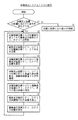
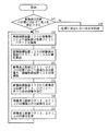
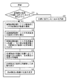
図2は、画像表示システム100において、画像表示装置DP1、DP2が画像表示するまでのプロセスを示すフローチャートである。 FIG. 2 is a flowchart showing a process until the image display devices DP1 and DP2 display an image in the image display system 100.
まず、画像表示に際して、画像表示装置DP1、DP2のそれぞれの位置情報に対応させて、画像表示装置DP1、DP2の表示画像を変化させる表示モードを選択するのか、または、画像表示装置DP1、DP2の位置情報に関わらずに、表示を行なう表示モードを選択するのかについて、ユーザが決定する(S1)。この表示モードを、ユーザが選択決定する場合、画像制御装置30の外部入力部38を介して接続する装置からの指示や、不図示の操作部を使用するようにしてもよく、画像表示装置DP1、DP2を使用するようにしてもよい。
First, at the time of image display, the display mode for changing the display image of the image display devices DP1 and DP2 is selected in accordance with the position information of the image display devices DP1 and DP2, or the image display devices DP1 and DP2 are selected. The user decides whether to select a display mode for display regardless of the position information (S1). When the user selects and decides on this display mode, an instruction from a device connected via the external input unit 38 of the
画像表示装置DP1、DP2の位置情報に対応させて、画像表示装置DP1、DP2における表示画像を変化させる必要がなければ(S1)、位置に依存しない表示を持続する(S9)。 If it is not necessary to change the display images on the image display devices DP1 and DP2 in correspondence with the position information of the image display devices DP1 and DP2 (S1), the display independent of the position is continued (S9).
画像表示装置DP1、DP2の位置情報に対応させて、画像表示装置DP1、DP2における表示画像を変化させる場合(S1)、画像表示装置DP1、DP2の位置を検出するプロセスへ進む。 When the display images on the image display devices DP1 and DP2 are changed corresponding to the position information of the image display devices DP1 and DP2 (S1), the process proceeds to a process of detecting the positions of the image display devices DP1 and DP2.
画像表示装置DP1、DP2を位置検出する場合、画像制御装置30の位置検出部37から、各画像表示装置DP1、DP2へ光照射し(S2)、画像表示装置DP1、DP2の位置検出部17、27が、上記照射光を反射し(S3)、画像制御装置30が、画像表示装置DP1、DP2のそれぞれの位置を算出する(S4)。
When the positions of the image display devices DP1 and DP2 are detected, light is emitted from the
画像制御装置30が、画像表示装置DP1、DP2の位置を算出した後に(S4)、画像制御装置30は、各画像表示装置DP1、DP2の位置に応じて、表示画像の大きさ、傾き等を含めた最適な表示画像を換算計算し、表示画像を再構築する(S5)。
After the
その後、画像制御装置30から各画像表示装置DP1、DP2へ、上記再構築された表示画像を送信し(S6)、画像表示装置DP1、DP2は、その位置に対応する再構築された表示画像を表示する(S7)。そして、画像表示装置の位置を変更する必要があれば、変更する(S8)。
Thereafter, the reconstructed display image is transmitted from the
次に、画像表示システム100において、画像表示装置DP1の位置を検出する動作について説明する。 Next, an operation for detecting the position of the image display device DP1 in the image display system 100 will be described.
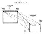
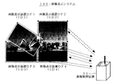
図3は、画像表示システム100において、画像表示装置DP1の位置を検出する動作の説明図である。 FIG. 3 is an explanatory diagram of an operation of detecting the position of the image display device DP1 in the image display system 100.
なお、画像表示システム100において、画像表示装置DP2等、他の画像表示装置の位置を検出する動作も、画像表示装置DP1の位置を検出する動作と同様である。 In the image display system 100, the operation of detecting the position of another image display device such as the image display device DP2 is the same as the operation of detecting the position of the image display device DP1.
画像制御装置30における位置検出部37は、同一面上に設けられている制御基準点37A、37B、37Cによって構成されている。画像表示装置DP1における位置検出部17は、その同一面上に設けられている表示基準点17A、17Bによって構成されている。
The
そして、画像制御装置30の制御基準点37A、37B、37Cから、画像表示装置DP1の表示基準点17A、17Bの位置を測定することによって、画像制御装置30から画像表示装置DP1までの距離と、画像制御装置30からみた画像表示装置DP1の傾きとを、相対位置として算出する。
Then, by measuring the positions of the
実施例1では、画像制御装置30の制御基準点37A、37B、37Cのそれぞれから、画像表示装置DP1の表示基準点17A、17Bのそれぞれに向けて、光パルスを送信し、この反射光を受信するまでの時間(パルスの往復飛行時間)を計測することによって、上記制御基準点と上記表示基準点との間の距離を求める。
In the first embodiment, light pulses are transmitted from the control reference points 37A, 37B, and 37C of the
次に、画像表示システム100における画像表示までの動作をより具体的に説明する。 Next, the operation up to image display in the image display system 100 will be described more specifically.
画像表示装置DP1、DP2の位置を検出する場合、画像制御装置30から画像表示装置DP1、DP2へ光を照射し、その反射光から距離を求める。つまり、三角測量によって位置を検出する。
When the positions of the image display devices DP1 and DP2 are detected, light is irradiated from the
まず、画像制御装置30の位置検出部37から各画像表示装置DP1、DP2へ光照射すると、各画像表示装置DP1、DP2の位置検出部17、27が光を反射し、画像制御装置30が、画像表示装置DP1、DP2の各位置を算出する。画像制御装置30が、画像表示装置DP1、DP2の位置を算出した後、画像制御装置30は、各画像表示装置DP1、DP2の位置に応じて最適な表示画像を換算計算する。その後、画像制御装置30から各画像表示装置DP1、DP2へ、各表示画像を送信し、画像表示装置DP1、DP2は、その位置に対応した最適な画像を表示する。
First, when light is irradiated from the
上記位置検出と表示画像の再構築とを、随時リアルタイムに行なうことによって、画像表示装置DP1、DP2の位置が変化しても、それに対応して表示画像を制御することができる。少なくとも、位置検出と、画像の再構成と、画像の表示とを、繰り返し行なうことによって、実用上は実現可能である。また、画像表示装置DP1、DP2の位置が変化した場合にのみ、画像の再構築を行なうことによって、画像処理工程を削減することができ、省エネルギーにもなる。 By performing the above-described position detection and display image reconstruction in real time as needed, even if the positions of the image display devices DP1 and DP2 change, the display image can be controlled accordingly. It can be practically realized by repeatedly performing at least position detection, image reconstruction, and image display. Further, by reconstructing an image only when the positions of the image display devices DP1 and DP2 change, it is possible to reduce the image processing steps and save energy.
次に、画像表示システム100における位置検出方法について、図3を用いてより詳細に説明する。現在実用化されている光を用いた測距方式は、およそ以下の3つである。
1.TOF(Time of Flight)式:光(電磁波)パルスを目標に向けて送信し、その反射波の受信までの時間(パルスの往復飛行時間)を計測することによって距離を求める方式。
2.位相差式:光(電磁波)を特定の周波数で変調したものを目標に連続照射し、受信した反射光との位相差を計測することによって距離を求める方式。
3.三角測量式:PSD(位置検出素子)を用いた三角測量の原理による測距方式で、PSD上の集光位置によって距離を求める方式。
Next, a position detection method in the image display system 100 will be described in detail with reference to FIG. There are roughly the following three ranging methods using light in practical use.
1. TOF (Time of Flight) formula: A method of obtaining a distance by transmitting a light (electromagnetic wave) pulse toward a target and measuring a time (reciprocation time of the pulse) until reception of the reflected wave.
2. Phase difference formula: A method for obtaining a distance by continuously irradiating light (electromagnetic wave) modulated at a specific frequency and measuring the phase difference with the received reflected light.
3. Triangulation method: A distance measurement method based on the principle of triangulation using a PSD (position detection element), and a method for obtaining a distance from a condensing position on the PSD.
また、上記と類似の方式、この他の方式等を用いるようにしてもよい。 Further, a method similar to the above or other methods may be used.
画像制御装置30は、同一面上に3箇所の位置検出部位37A、37B、37Cを有し、画像表示装置DP1、DP2は、その同一面上に2箇所の位置検出部位17A、17Bを有する。画像制御装置30の基準点3点から、画像表示装置DP1、DP2の基準点2点の位置を測定することによって、画像表示装置DP1、DP2の画像制御装置30に対する距離と傾きを、相対位置として算出する。
The
次に、画像制御装置30が行なう画像表示装置DP1、DP2のそれぞれにおいて表示する画像の再構築について説明する。
Next, reconstruction of an image displayed on each of the image display devices DP1 and DP2 performed by the
複数の画像表示装置を用いる利用形態としては、以下の通りである。 A usage form using a plurality of image display devices is as follows.
複数の画像表示装置が全て整然と縦横に並べて用いる場合を除き、多くの場合、複数の画像表示装置のうちで、1つの画像表示装置が、メインに用いられ、他は、それの補助として用いら場合がある。この場合、どれをメインにするかは使用者が容易に設定できるように入力装置が装備されていてもよい。 In many cases, one image display device is mainly used among the plurality of image display devices, and the other is used as an auxiliary thereof, except when a plurality of image display devices are used in an orderly manner. There is a case. In this case, an input device may be provided so that the user can easily set which is to be main.
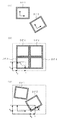
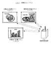
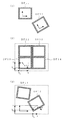
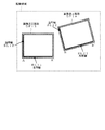
図4は、画像表示装置とコンテンツウインドウとの関係を示す図である。
1. 図4(1)に示すように、画像表示装置DP1、DP2と、各コンテンツウインドウの表示とを対応させて表示する場合であり、画像表示装置DP1、DP2の上下左右と、画像表示ウインドウの上下左右とが、一致し、固定して表示を行なう。
FIG. 4 is a diagram illustrating the relationship between the image display device and the content window.
1. As shown in FIG. 4A, the image display devices DP1 and DP2 and the display of each content window are displayed in correspondence with each other. The image display devices DP1 and DP2 are displayed vertically and horizontally, and the image display window is vertically displayed. The left and right sides match and are fixed for display.
画像表示装置DP1、DP2の位置に関わらずに、表示内容は、画像表示装置DP1、DP2の識別子ID1、ID2のみで決定される。全ての画像表示装置DP1、DP2に、同一の画像表示を行なう場合も含まれる。この場合、画像表示装置DP1、DP2へ送信する表示画像は、その位置に関わらず固定であるので、画像処理部33での画像処理は必要ではない。 Regardless of the position of the image display devices DP1 and DP2, the display content is determined only by the identifiers ID1 and ID2 of the image display devices DP1 and DP2. The case where the same image display is performed on all the image display devices DP1 and DP2 is also included. In this case, the display image to be transmitted to the image display devices DP1 and DP2 is fixed regardless of its position, and therefore image processing in the image processing unit 33 is not necessary.
この場合、画像表示装置DP1、DP2のそれぞれの位置関係が変わると、表示画像を交換することができる。たとえば、右から左に向かって、画像表示装置DP1、DP2、DP3の並びが、画像表示装置DP1、DP3、DP2と変わった場合、画像表示装置DP2に表示していた表示画像と、画像表示装置DP3に表示していた表示画像を交換することによって、表示画像の内容の連続性が保たれる場合がある。もちろん、画像表示装置DP1、DP2の場所に関わらず、同じ画像を表示し続ける場合もある。
2. 図4(2)に示すように、複数の画像表示装置DP1、DP2、DP3、DP4を縦横に整列させてシームレスなコンテンツ画像を大画面で表示でき、迫力のある大画面表示装置として用いることが可能である。この場合、画像表示装置DP1〜DP4が無線によって画像制御装置30と接続されているので、配線は不要であり、画像表示装置DP1〜DP4の位置に応じて、最適な画像を自動的に表示するので、配置は極めて容易である。この場合、画像表示装置DP1〜DP4のそれぞれは、大画面表示の画像(x、y)に対して平行に(kx、ky)だけシフトして配置されるので、画像表示装置DP1〜DP4のそれぞれにおける表示画像の座標は、(x−kx、y−ky)である。
3. 図4(3)に示すように、画像表示装置DP1、DP2は、仮想の大画面映像の一部を表示し、画像表示装置DP1、DP2の位置や向きに応じて、仮想の大画面映像が崩れないように、画像表示装置DP1、DP2上に表示する映像は変化する。
In this case, when the positional relationship between the image display devices DP1 and DP2 changes, the display images can be exchanged. For example, when the arrangement of the image display devices DP1, DP2, and DP3 changes from the right to the left as the image display devices DP1, DP3, and DP2, the display image displayed on the image display device DP2 and the image display device By exchanging the display image displayed on DP3, the continuity of the content of the display image may be maintained. Of course, the same image may continue to be displayed regardless of the location of the image display devices DP1 and DP2.
2. As shown in FIG. 4 (2), a plurality of image display devices DP1, DP2, DP3, DP4 can be arranged vertically and horizontally to display a seamless content image on a large screen, and used as a powerful large screen display device. Is possible. In this case, since the image display devices DP1 to DP4 are wirelessly connected to the
3. As shown in FIG. 4 (3), the image display devices DP1 and DP2 display a part of the virtual large screen image, and the virtual large screen image is displayed according to the position and orientation of the image display devices DP1 and DP2. The video displayed on the image display devices DP1 and DP2 changes so as not to collapse.
つまり、画像表示装置DP1を移動させると、その位置に応じて画像が変化し、仮想の画像の一部を表示する窓のように機能する。これを実現するためには、仮想の表示画像の座標と、画像表示装置DP1上の座標とを、その相対位置関係において変換する。たとえば、仮想の表示画像の左下を基準にした場合における仮想の表示画像の画素の座標を(x、y)とし、画像表示装置DP1の左下の位置が、仮想の表示画像に対して、(kx、ky)だけ移動し、θだけ傾くとすると、画像表示装置DP1における表示画像の画素の座標(X,Y)に表示すべき表示画像の座標(x、y)は、以下の通りである。
X=(x−kx)cosθ+(y−ky)sinθ
Y=(y−ky)cosθ−(x−kx)sinθ
また、表示方式は上記1〜3に限られるものではなく、これらの組合せ等が任意に選択される。
That is, when the image display device DP1 is moved, the image changes according to the position, and functions as a window that displays a part of the virtual image. In order to realize this, the coordinates of the virtual display image and the coordinates on the image display device DP1 are converted in the relative positional relationship. For example, the coordinate of the pixel of the virtual display image when the lower left of the virtual display image is used as a reference is (x, y), and the lower left position of the image display device DP1 is (k x , k y ) is moved and tilted by θ, the coordinates (x, y) of the display image to be displayed at the coordinates (X, Y) of the pixel of the display image in the image display device DP1 are as follows: is there.
X = (x−k x ) cos θ + (y−k y ) sin θ
Y = (y−k y ) cos θ− (x−k x ) sin θ
Further, the display method is not limited to the above 1 to 3, and a combination thereof is arbitrarily selected.
画像制御装置30から、画像表示装置への画像の伝送方法については、無線方式の移動体通信による。複数の画像表示装置への伝送は、各識別子IDに対応して、周波数分割多重方式、時間分割多重方式、符号分割多重方式等による同時に各映像信号に合わせて、複数の画像表示装置へ伝送を行なう。
An image transmission method from the
画像表示装置には、デジタイザ、スイッチ等が設けられ、所望の動作を、画像表示装置側から制御することができるようにしてもよい。 The image display device may be provided with a digitizer, a switch, and the like so that a desired operation can be controlled from the image display device side.
図5は、画像表示システム100において、画像表示装置DP1〜DP4をタイリングして大画面を表示する例を模式的に示す図である。 FIG. 5 is a diagram schematically showing an example of displaying a large screen by tiling the image display devices DP <b> 1 to DP <b> 4 in the image display system 100.
画像表示装置DP3、DP4は、画像表示装置DP1、DP2と同様の装置である。 The image display devices DP3 and DP4 are the same devices as the image display devices DP1 and DP2.
図5に示す画像表示システム100は、4台の画像表示装置をタイリングして大画面表示している例であり、このように、多数のフラットパネルディスプレイをタイリングして壁面に沿って設置することによって、壁面一面を画像表示することができる。この場合、画像表示装置DP1と同様の5台の画像表示装置を追加し、縦3台、横3台、合計9台で表示する表示モードを選択することによって、9台のタイリングディスプレイシステムに大画面表示することができる。この際、表示画像を拡大し、各画像表示装置の位置に対応する画像を再構成する。 The image display system 100 shown in FIG. 5 is an example in which four image display devices are tiled and displayed on a large screen. Thus, a large number of flat panel displays are tiled and installed along a wall surface. By doing so, the entire wall surface can be displayed as an image. In this case, five image display devices similar to the image display device DP1 are added, and a display mode for displaying a total of nine devices in three vertical and three horizontal directions is selected. Can be displayed on a large screen. At this time, the display image is enlarged and an image corresponding to the position of each image display device is reconstructed.
図6は、画像表示システム100において、互いに同じ画像表示装置DP1、DP2、DP3、DP4によって大画面が構成され、そのうちの画像表示装置DP1を、上記構成された大画面の中央部へ移動させた場合を示す図である。 FIG. 6 shows that in the image display system 100, a large screen is configured by the same image display devices DP1, DP2, DP3, and DP4, and the image display device DP1 is moved to the central portion of the configured large screen. It is a figure which shows a case.
この場合、画像表示装置DP1へ表示する表示画像は、画像表示装置DP1の位置が移動することに合わせて、リアルタイムにフィードバックがかかり、あたかも画像表示装置DP1が仮想の大画面表示の一部を表示する窓のように作用する。 In this case, the display image displayed on the image display device DP1 is fed back in real time as the position of the image display device DP1 moves, as if the image display device DP1 displays a part of the virtual large screen display. Acts like a window.
図7は、画像表示システム100において、画像表示装置DP1、DP2、DP3が互いに異なる内容を表示している例を示す図である。 FIG. 7 is a diagram illustrating an example in which the image display apparatuses DP1, DP2, and DP3 display different contents in the image display system 100.
この場合、表示装置の位置に関わらず、表示内容と画像表示装置DP1、DP2、DP3と、画像制御装置30とを、一対一に対応させ、上記画像変換を行なわない。
In this case, regardless of the position of the display device, the display content, the image display devices DP1, DP2, DP3, and the
図5、図6、図7に示す実施例において、上記複数の画像表示装置のうちの一部の画像表示装置において、上記大画面映像を表示し、残りの画像表示装置において、上記大画面映像とは異なる画像を表示するようにしてもよい。
5, 6, and 7, the large screen video is displayed on some of the plurality of image display devices, and the large screen video is displayed on the remaining image display devices. Different images may be displayed.
本発明の実施例2は、画像表示システム100において、画像表示装置DP1にメモリ性を持たせた実施例である。 The second embodiment of the present invention is an embodiment in which the image display device DP1 has a memory property in the image display system 100.
このメモリ性を有する画像表示装置DP1は、ペーパーライクディスプレイであり、たとえば、電気泳動方式で微粒子が移動することによって白黒表示やカラー表示を行なうディスプレイである。 The image display device DP1 having a memory property is a paper-like display, for example, a display that performs black and white display or color display by moving fine particles by electrophoresis.
この場合、表示の書き換え時以外は、電力を必要としないので、画像表示装置DP1の省電力に有効である。特に、電子ブック、ビジネス用途のテキスト中心の書類、広告看板、ポスター等の用途に適している。 In this case, power is not required except when the display is rewritten, which is effective for power saving of the image display device DP1. In particular, it is suitable for applications such as electronic books, text-centric documents for business use, advertising signs, posters, and the like.
また、メモリ性を有する画像表示装置DP1と同じ画像表示装置を複数、設ければ、従来、複数枚の紙を広げて行なう作業に置き換えることができ、便利である。
In addition, providing a plurality of image display devices that are the same as the image display device DP1 having a memory property is convenient because it can be replaced with an operation conventionally performed by spreading a plurality of sheets of paper.
図8は、本発明の実施例3である画像表示システム200を示す図である。
FIG. 8 is a diagram showing an image display system 200 that is
画像表示システム200は、画像表示システム100において、画像表示装置DP1を、マスタ画像表示装置とし、画像表示装置DP2を、スレーブ画像表示装置とし、マスタ画像表示装置DP1が、マスタ画像表示装置DP1からスレーブ画像表示装置DP2までの距離と方向とを測定することによって、画像表示装置DP1に対する画像表示装置DP2の位置を検出する実施例である。 The image display system 200 is the image display system 100 in which the image display device DP1 is a master image display device, the image display device DP2 is a slave image display device, and the master image display device DP1 is a slave from the master image display device DP1. In this embodiment, the position of the image display device DP2 relative to the image display device DP1 is detected by measuring the distance and direction to the image display device DP2.
画像表示システム200において、マスタ画像表示装置DP1は、有機ELディスプレイからなる画像表示部11と、画像駆動部12と、表示画像の伸張、映像信号の受信等を行う処理部13と、画像制御装置30との間でデータ送受信する無線通信部14と、電源部15と、画像表示装置DP1、DP2を区別する識別子ID1他を内蔵する記憶部16と、光送信器と光検出器によって構成されている位置検出部17とを有し、マスタ画像表示装置DP1は、画像表示のための基準となり、ユーザから見て基準となる表示画像を表示する。
In the image display system 200, a master image display device DP1 includes an
スレーブ画像表示装置DP2は、有機ELディスプレイからなる画像表示部21と、画像駆動部22と、表示画像の伸張、映像信号の受信等を行なう処理部23と、画像制御装置30との間でデータ送受信する無線通信部24と、電源部25と、画像表示装置DP1、DP2を区別するための識別子ID2他を内蔵する記憶部26と、位置検出部27とを有する。
The slave image display device DP2 includes data between an image display unit 21 including an organic EL display, an image drive unit 22, a processing unit 23 that performs display image expansion, video signal reception, and the like, and an
位置検出部27は、光反射器を有する。 The position detection unit 27 has a light reflector.
マスタ画像表示装置DP1が、マスタ画像表示装置DP1を基準として、スレーブ画像表示装置DP2の位置を決定する。マスタ画像表示装置DP1に対するスレーブ画像表示装置DP2の位置情報を、画像制御装置30に送信する。
The master image display device DP1 determines the position of the slave image display device DP2 with reference to the master image display device DP1. The position information of the slave image display device DP2 with respect to the master image display device DP1 is transmitted to the
画像制御装置30は、制御部39において、画像表示システム200における全ての画像表示装置DP1、DP2の位置を把握し、画像表示装置DP1、DP2のそれぞれに対応する表示画像を各位置に応じて再構築し、この再構築された各表示画像を、画像表示装置DP1、DP2へ無線通信によって伝送し、管理する。
In the
特に、画像処理部33は、画像表示装置DP1、DP2のそれぞれの位置に応じた表示画像を形成するために、画像の再構築を行ない、無線通信部34は、全ての画像表示装置DP1、DP2との間で、データを送受信する。 In particular, the image processing unit 33 reconstructs images in order to form display images corresponding to the positions of the image display devices DP1 and DP2, and the wireless communication unit 34 includes all the image display devices DP1 and DP2. Send and receive data to and from.
表示部31は、画像表示システム200の制御情報を表示し、画像表示システム200全体で表示する画像を簡略表示し、表示モードをユーザが選択をするための表示を行なう。 The display unit 31 displays control information of the image display system 200, displays an image displayed on the entire image display system 200, and performs a display for the user to select a display mode.
また、画像制御装置30は、外部入力部38と、電源部35とを有する。
In addition, the
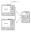
次に、画像表示システム200において、画像表示装置DP1、DP2が画像表示するまでの動作について説明する。 Next, operations in the image display system 200 until the image display devices DP1 and DP2 display an image will be described.
図9は、画像表示システム200において、画像表示装置DP1、DP2が画像表示するまでの動作を示すフローチャートである。 FIG. 9 is a flowchart showing an operation until the image display devices DP1 and DP2 display an image in the image display system 200.
まず、スレーブ画像表示装置DP2の位置を検出するために、マスタ画像表示装置DP1の位置検出部17が、スレーブ画像表示装置DP2へ光照射すると(S11)、スレーブ画像表示装置DP2の位置検出部27が、光を反射し(S12)、マスタ画像表示装置DP1が、スレーブ画像表示装置DP2からの反射光を検出し、この検出した光に基づいて、スレーブ画像表示装置DP2の位置を算出する(S13)。 First, in order to detect the position of the slave image display device DP2, when the position detection unit 17 of the master image display device DP1 irradiates the slave image display device DP2 (S11), the position detection unit 27 of the slave image display device DP2 is irradiated. However, the master image display device DP1 detects the reflected light from the slave image display device DP2, and calculates the position of the slave image display device DP2 based on the detected light (S13). ).
その後、マスタ画像表示装置DP1は、マスタ画像表示装置DP1とスレーブ画像表示装置DP2との相対的な位置関係、つまり、マスタ画像表示装置DP1を基準としたスレーブ画像表示装置DP2の位置を算出し、画像制御装置30に送信する。画像制御装置30は、画像表示装置DP1、DP2のそれぞれの位置に応じて最適な表示画像を換算計算し、表示画像を再構築する(S14)。そして、画像制御装置30から各画像表示装置DP1、DP2へ、各表示画像を送信し(S15)、画像表示装置DP1、DP2は、その位置に対応した最適な画像(再構築された表示画像)を表示する(S16)。
Thereafter, the master image display device DP1 calculates the relative positional relationship between the master image display device DP1 and the slave image display device DP2, that is, the position of the slave image display device DP2 with respect to the master image display device DP1. It transmits to the
画像表示システム200において、複数の画像表示装置のうち、1台はマスタ画像表示装置として、表示画像について、画像制御装置30が絶対的な位置合わせがなされ、他の画像表示装置は、スレーブ画像表示装置として、マスタ画像表示装置に対する相対的な位置に合わせを行ない、表示画像を変化させるので、画像制御装置30から光による位置検出ができない場所以外にも画像表示装置を配置することができ、画像表示装置の配置に自由度を持たせることができる。
In the image display system 200, one of the plurality of image display devices is used as a master image display device, the
また、画像制御装置30の位置に関わらず、マスタ画像表示装置DP1の位置に応じて大画面表示の位置を決定できるので、より使いやすいシステムを実現できる。
Further, since the position of the large screen display can be determined according to the position of the master image display device DP1 regardless of the position of the
本発明の実施例4は、表示画像の再構築を、画像表示装置が行なう実施例である。 The fourth embodiment of the present invention is an embodiment in which an image display device performs reconstruction of a display image.
第4の実施例の構成は、基本的には、画像表示システム100と同様であるので、第4の実施例の説明を、画像表示システム100に則して行なう。 Since the configuration of the fourth embodiment is basically the same as that of the image display system 100, the description of the fourth embodiment will be made according to the image display system 100.
第4の実施例は、次の第1の方式、第2の方式の2つの方式が考えられる。 In the fourth embodiment, the following two systems, the first system and the second system, can be considered.
第1の方式は、画像表示システム100において、マスタ画像表示装置DP1は、実施例3と同様にしてスレーブ表示装置DP2の位置を測定、算出し、画像制御装置30からの画像をマスタ画像表示装置DP1が表示画像を再構築し、この再構築した表示画像を、スレーブ画像表示装置DP2へ伝送し、表示する方式である。
In the first method, in the image display system 100, the master image display device DP1 measures and calculates the position of the slave display device DP2 as in the third embodiment, and the image from the
第2の方式は、実施例1、実施例3のように、画像制御装置30、または、マスタ画像表示装置DP1が各画像表示装置の位置を測定し、測定した各画像表示装置の位置を夫々の画像表示装置に通知し、各画像表示装置が他の画像表示装置との相対位置を認識する。そして、画像制御装置30から各画像表示装置に表示画像(元画像)をブロードキャストし、各画像表示装置が自分の位置に応じた表示画像を構築して表示する方式である。
In the second method, as in the first and third embodiments, the
第1、第2の方式の場合、画像制御装置30の機能の一部を、マスタ画像表示装置DP1または各画像表示装置が担うので、画像制御装置30の画像処理機能が不要になり、画像制御装置30からは元画像がそのまま伝送される。
In the case of the first and second methods, the master image display device DP1 or each image display device bears a part of the functions of the
第1の方式の場合は、マスタ画像表示装置DP1は、マスタ画像表示装置DP1が表示する画像を中心として再構築する。 In the case of the first method, the master image display device DP1 reconstructs mainly the image displayed by the master image display device DP1.
つまり、マスタ画像表示装置DP1における表示画像の位置基準を固定し、マスタ画像表示装置DP1における表示画像を構築し、マスタ画像表示装置DP1に対するスレーブ画像表示装置DP2の相対位置に対して、スレーブ画像表示装置DP2が表示する表示画像を再構築する。 That is, the position reference of the display image in the master image display device DP1 is fixed, the display image in the master image display device DP1 is constructed, and the slave image display is performed with respect to the relative position of the slave image display device DP2 with respect to the master image display device DP1. The display image displayed by the device DP2 is reconstructed.
また、第2の方式の場合は、各画像表示装置が、認識している自装置の位置に応じた表示画像を元画像から構築し、表示することになる。 In the case of the second method, each image display device constructs and displays a display image corresponding to the position of the recognized own device from the original image.
次に、実施例4における第1の方式での動作について説明する。 Next, the operation of the first method in the fourth embodiment will be described.
図20は、本発明の実施例4における第1の方式での動作を示すフローチャートである。 FIG. 20 is a flowchart showing the operation of the first method in the fourth embodiment of the present invention.
まず、画像表示システム100において、マスタ画像表示装置DP1は、実施例3と同様にして、スレーブ表示装置DP2の位置を測定、算出し(S11〜S13)、画像制御装置30からの画像を、スレーブ画像表示装置DP2の位置に応じて、マスタ画像表示装置DP1が再構築し(S54)、この再構築した表示画像を、マスタ画像表示装置DP1がスレーブ画像表示装置DP2へ伝送し(S55)、スレーブ画像表示装置DP2が、再構築された画像を表示する(S56)。
First, in the image display system 100, the master image display device DP1 measures and calculates the position of the slave display device DP2 in the same manner as in the third embodiment (S11 to S13), and the image from the
次に、実施例4における第2の方式での動作について説明する。 Next, the operation of the second method in the fourth embodiment will be described.
図10は、本発明の実施例4における第2の方式での動作を示すフローチャートである。 FIG. 10 is a flowchart showing the operation of the second method in the fourth embodiment of the present invention.
まず、画像表示装置DP1、DP2を位置検出する場合、画像制御装置30の位置検出部37から、各画像表示装置DP1、DP2へ光照射すると(S21)、画像表示装置DP1、DP2の位置検出部17、27が光を反射し(S22)、画像制御装置30が、画像表示装置DP1、DP2のそれぞれの位置を算出する(S23)。
First, in the case of detecting the positions of the image display devices DP1 and DP2, when the light is emitted from the
画像制御装置30が、画像表示装置DP1、DP2の位置を算出した後に、画像制御装置30から、画像表示装置DP1、DP2の位置情報と表示画像とを送信し(S24)、画像表示装置DP1、DP2の位置情報に応じて、最適な表示画像を、画像表示装置DP1、DP2が、自身で再構築する(S25)。そして、この再構築された表示画像を、画像表示装置DP1、DP2が表示する(S26)。
After the
画像制御装置30は、表示画像の再構築を必要としないので、画像表示装置の数が多い場合、画像処理の負荷と画像伝送の負荷とを軽減することができ、したがって、画像表示装置の数が多い場合に、特に適している。また、画像表示装置を縦横に整列させて用いるタイリングの大画面表示に適している。
Since the
上記各実施例において、複数枚の画像表示装置を用いて表示する場合の特色は、以下のとおりである。
1. 各画像表示装置と各コンテンツウインドウの表示とを対応させて表示するので、各画像表示装置の上下左右と、画像表示ウインドウの上下左右とを、一致させ、この一致したままの状態で、表示することができる。各画像表示装置の位置に関わらずに、表示内容は、各画像表示装置の識別子IDのみで決定される。この場合、全ての画像表示装置に、同一の画像表示を行なうようにしてもよい。
2. 複数の画像表示装置を、縦横に整列させ、シームレスなコンテンツ画像を大画面で表示することができ、迫力のある大画面表示装置を構成することができる。この場合、画像表示装置は、無線によって画像制御装置と接続しているので、配線を不要とし、画像表示装置の位置に応じて、最適な画像を自動的に表示するので、配置が極めて容易である。
3. 各画像表示装置は、仮想の大画面映像の一部を表示し、画像表示装置の位置や向きに応じて、仮想の大画面映像が崩れないように、画像表示装置上に表示する映像の位置と傾きとが制御される。つまり、画像表示装置を移動させると、その位置に応じて画像が変化し、仮想の画像の一部を表示する窓のように機能する。
In each of the above-described embodiments, the characteristics when displaying using a plurality of image display devices are as follows.
1. Since each image display device and each content window are displayed in correspondence with each other, the top, bottom, left and right of each image display device are matched with the top, bottom, left and right of the image display window, and the images are displayed in the same state. be able to. Regardless of the position of each image display device, the display content is determined only by the identifier ID of each image display device. In this case, the same image display may be performed on all the image display devices.
2. A plurality of image display devices can be arranged vertically and horizontally to display a seamless content image on a large screen, and a powerful large screen display device can be configured. In this case, since the image display device is wirelessly connected to the image control device, no wiring is required, and an optimum image is automatically displayed according to the position of the image display device, so that the arrangement is extremely easy. is there.
3. Each image display device displays a part of the virtual large screen image, and the position of the image displayed on the image display device so that the virtual large screen image does not collapse according to the position and orientation of the image display device. And tilt are controlled. That is, when the image display apparatus is moved, the image changes according to the position, and functions as a window that displays a part of the virtual image.
複数の画像表示装置を用いる場合、表示するコンテンツの内容、作業の内容によって、上記特色1〜3が組み合わされ、表示内容を制御する。
When a plurality of image display apparatuses are used, the above-mentioned
この場合、画像表示装置には、デジタイザ、または表示モードの切り替えスイッチ等が具備され、表示させたい表示モードを、ユーザが容易に切り替えることができる。 In this case, the image display device includes a digitizer, a display mode changeover switch, or the like, and the user can easily switch the display mode to be displayed.
画像表示装置DP1、DP2を構成するペーパーディスプレイには、電気泳動型ディスプレイ、トナーディスプレイ、ツイスティッドボール・ディスプレイ、反射型のメモリ性のある液晶ディスプレイ等があり、フレキシブルディスプレイには、プラスチック基板上に形成した液晶ディスプレイ、有機ELディスプレイ等がある。 The paper displays constituting the image display devices DP1 and DP2 include an electrophoretic display, a toner display, a twisted ball display, a reflective liquid crystal display, and the like. A flexible display is formed on a plastic substrate. There are formed liquid crystal displays, organic EL displays and the like.
上記実施例によれば、複数の画像表示装置がその位置に対応して、最適に画像を表示することができ、これによって、複数の画像表示装置を有効に活用することができる。また、上記実施例によれば、画像表示装置の連携によって、ユーザによる表示切替が容易である。 According to the above-described embodiment, a plurality of image display devices can optimally display an image corresponding to the position, whereby the plurality of image display devices can be effectively utilized. Further, according to the above embodiment, display switching by the user is easy by cooperation of the image display apparatus.
つまり、上記実施例によれば、画像表示装置の上下左右と、表示画像の上下左右とを一致させて固定し、表示を行なう複数の画像表示装置を用いたディスプレイシステムを提供することができる。 That is, according to the above-described embodiment, it is possible to provide a display system using a plurality of image display devices that perform display by fixing the image display device in the vertical and horizontal directions and the vertical and horizontal directions of the display image.
また、上記実施例によれば、複数の画像表示装置を縦横に整列させて大画面表示を行なうことができ、設置が容易である大画面ディスプレイシステムを提供することができる。 Further, according to the above-described embodiment, a large screen display system can be provided which can display a large screen by arranging a plurality of image display devices vertically and horizontally and can be easily installed.
さらに、上記実施例によれば、各画像表示装置は、仮想の大画面映像の一部を表示し、上記画像表示装置の位置や傾きに応じて、仮想の大画面映像が崩れないように、上記画像表示装置上に表示する映像の位置と傾きが制御されるディスプレイシステムを提供することができる。 Furthermore, according to the above-described embodiment, each image display device displays a part of the virtual large-screen image, and the virtual large-screen image does not collapse according to the position and tilt of the image display device. It is possible to provide a display system in which the position and inclination of a video displayed on the image display device are controlled.
特に、上記特色3に関しては、従来ない複数枚のフラットパネルディスプレイの使用形態を可能にし広告、看板等の装飾的なディスプレイ表示システムとしても有効である。
In particular, with respect to the above-mentioned
また、上記特色2に関しても、ユーザが粗い精度で複数枚のディスプレイを整列させても、ゆがみのない連続な大画面表示を実現できるので、多数人数による会議等での共同作業や判断等に最適な画像表示システムを実現できる。
In addition, for the
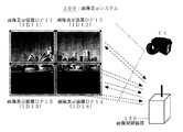
図11は、本発明の実施例5である画像表示システム300を示す図である。 FIG. 11 is a diagram showing an image display system 300 that is Embodiment 5 of the present invention.
画像表示システム300は、画像表示装置DP11、DP12と、画像制御装置130とを有する。
The image display system 300 includes image display devices DP11 and DP12 and an
画像表示装置DP11は、画像表示部111と、画像駆動部112と、処理部113と、無線通信部114と、電源部115と、識別子ID11他を内蔵する記憶部116と、基準線BL1(または2つの基準点)とを有する。
The image display device DP11 includes an image display unit 111, an image drive unit 112, a
画像表示部111は、その位置情報に対応した表示画像を表示することができ、基準線BL1は、画像表示装置DP11の外周境界線である。 The image display unit 111 can display a display image corresponding to the position information, and the reference line BL1 is an outer peripheral boundary line of the image display device DP11.
画像表示装置DP12の構成は、画像表示装置DP11と同様である。つまり、画像表示装置DP12は、画像表示部121と、画像駆動部122と、処理部123と、無線通信部124と、電源部125と、識別子ID12他を内蔵する記憶部126と、基準線BL2(または2つの基準点)を有している。画像表示装置DP12は、その位置情報に対応した表示画像を表示する。
The configuration of the image display device DP12 is the same as that of the image display device DP11. That is, the image display device DP12 includes an image display unit 121, an image driving unit 122, a
画像表示部111、121は、TFT駆動液晶ディスプレイまたはフラットパネルディスプレイの表示部であり、ペーパーディスプレイ、フレキシブルディスプレイ等である。ペーパーディスプレイには、電気泳動型ディスプレイ、トナーディスプレイ、ツイスティッドボール・ディスプレイ、反射型のメモリ性のある液晶ディスプレイ等があり、フレキシブルディスプレイには、プラスチック基板上に形成した液晶ディスプレイ、有機ELディスプレイ等がある。 The image display units 111 and 121 are display units of a TFT drive liquid crystal display or a flat panel display, such as a paper display and a flexible display. Paper displays include electrophoretic displays, toner displays, twisted ball displays, reflective liquid crystal displays with memory characteristics, etc. Flexible displays include liquid crystal displays formed on plastic substrates, organic EL displays, etc. There is.
画像駆動部112、122は、画像表示部111、121の駆動回路部であり、走査線駆動回路、信号線駆動回路、DA変換回路、タイミングコントロール回路、グラフィックス・コントローラ・インタフェース等である。 The image drive units 112 and 122 are drive circuit units of the image display units 111 and 121, and are a scanning line drive circuit, a signal line drive circuit, a DA conversion circuit, a timing control circuit, a graphics controller interface, and the like.
処理部113、123は、表示画像の伸張、映像信号の受信等を行ない、低消費電力を維持しながら、無線通信によって取り込まれた画像信号を画像表示部111、121が表示することを制御処理する。
The
電源部115、125は、画像表示、無線通信、位置検出、各種処理によって必要な電力を管理し、供給する。
The
識別子ID11、ID12は、画像表示装置DP11、DP12にそれぞれ割り振られたID情報であり、位置検出時、通信時のデータの受渡し時に、画像表示装置DP11、DP12のそれぞれを識別するために用いる。 The identifiers ID11 and ID12 are ID information assigned to the image display devices DP11 and DP12, respectively, and are used to identify each of the image display devices DP11 and DP12 at the time of position detection and data transfer during communication.
記憶部116、126は、識別子IDを記憶し、位置情報、表示画像等を一時的に記憶する場合もある。 The storage units 116 and 126 may store identifier IDs and temporarily store position information, display images, and the like.
基準線BL1、BL2は、画像表示装置DP11、DP12の規定の場所に設定され、その位置、基準線の長さは既知である。また、基準線BL1、BL2は、2つ以上の基準点によって構成され、それらの位置と間隔が既知であってもよい。 The reference lines BL1 and BL2 are set at specified locations of the image display devices DP11 and DP12, and their positions and the lengths of the reference lines are known. Further, the reference lines BL1 and BL2 may be constituted by two or more reference points, and their positions and intervals may be known.
画像制御装置130は、表示部131と、画像処理部133と、無線通信部134と、電源部135と、記憶部136と、位置検出部137と、外部入力部138と、制御部139とを有する。
The
表示部131は、画像表示システム300の制御情報の表示、画像表示システム300全体の表示画像の簡略表示、表示モードの選択のための表示を行う。
The
画像処理部133は、画像表示装置DP11、DP12のそれぞれの表示画像を構成する処理部であり、複数の表示装置の表示モード、画像表示装置DP11、DP12の位置に応じて、表示画像を再構築する。 The image processing unit 133 is a processing unit that configures each display image of the image display devices DP11 and DP12, and reconstructs the display image according to the display mode of the plurality of display devices and the positions of the image display devices DP11 and DP12. To do.
無線通信部134は、複数の画像表示装置DP11、DP12と無線通信を行ない、表示画像を送信し、画像表示装置DP11、DP12に入力された情報を受信する機能部であり、RF回路部、アンテナ、A−D/D−A変換回路等を有する。 The wireless communication unit 134 is a functional unit that performs wireless communication with the plurality of image display devices DP11 and DP12, transmits display images, and receives information input to the image display devices DP11 and DP12. The RF circuit unit and the antenna And an AD / DA conversion circuit.
電源部135は、画像処理、無線通信、位置検出、画像表示、制御、入力、記録等のために必要な電力を管理し、供給する。
The
位置検出部137は、撮像部C1を有する。撮像部C1は、画像表示装置DP11、DP12を撮像し、画像表示装置DP11、DP12上の基準線BL1、BL2を用いることによって、画像表示装置DP11、DP12の位置を相対的に算出し、画像表示装置DP11、DP12へ、最適な表示画像データを伝送する。 The position detection unit 137 includes an imaging unit C1. The imaging unit C1 captures the image display devices DP11 and DP12, uses the reference lines BL1 and BL2 on the image display devices DP11 and DP12, relatively calculates the positions of the image display devices DP11 and DP12, and displays the images. Optimal display image data is transmitted to the devices DP11 and DP12.
制御部139は、画像表示システム300における全ての画像表示装置DP11、DP12の位置を把握し、画像表示装置DP11、DP12のそれぞれに対応する表示画像を各位置に応じて再構築し、各上記表示画像を画像表示装置DP11、DP12へ無線通信によって伝送することを管理している。また、外部入力部138において、外部ネットワークと接続されている場合、外部信号との同期についても制御する。
The
次に、画像制御装置130における位置検出部137について説明する。
Next, the position detection unit 137 in the
位置検出部137は、撮像部C1と、撮像した像に基づいて、画像表示装置DP11、DP12の位置を算出する位置算出処理部とによって構成され、その間は有線通信、または無線通信によって繋がっている。また、撮像部C1は、制御部139と一体になっていてもよく、たとえば、撮像部C1であるカメラに他の機能が付加され、画像制御装置130と一体となっていてもよい。
The position detection unit 137 includes an imaging unit C1 and a position calculation processing unit that calculates the positions of the image display devices DP11 and DP12 based on the captured image, and is connected by wired communication or wireless communication. . Further, the imaging unit C1 may be integrated with the
位置検出の方法は、撮像部C1が、全ての画像表示装置DP11、DP12を撮影し、画像表示装置DP11、DP12上の既知である基準線BL1、BL2(または2つ以上の基準点)を検出し、その像内における画像表示装置DP11、DP12の相対位置を実際の距離に換算して算出することができる。 In the position detection method, the imaging unit C1 images all the image display devices DP11 and DP12 and detects the known reference lines BL1 and BL2 (or two or more reference points) on the image display devices DP11 and DP12. Then, the relative position of the image display devices DP11 and DP12 in the image can be calculated by converting into the actual distance.
表示部131は、画像表示装置DP11、DP12の表示方法を制御するための表示を行ない、表示画像の全て、または一部の表示を行ない、仮想表示画像を表示し、画像表示装置DP11、DP12と表示画像との位置関係を表示し、外部ネットワークとの接続情報を表示する。
The
外部入力部138は、画像制御装置130を介して、画像表示システム300が、コンピュータや、ネットワークと接続されている場合における入力インタフェース部である。これによって、画像表示システム300を汎用的な表示装置として用いることができる。
The external input unit 138 is an input interface unit when the image display system 300 is connected to a computer or a network via the
次に、画像表示システム300における画像表示までのプロセスについて説明する。 Next, a process until image display in the image display system 300 will be described.
図12は、画像表示システム300における画像表示までのプロセスを示すフローチャートである。 FIG. 12 is a flowchart showing a process until image display in the image display system 300.
まず、画像表示に際して、画像表示装置DP11、DP12の位置情報に対応させて、画像表示装置DP11、DP12の表示画像を変化させるのか、または、画像表示装置DP11、DP12の位置情報に合わせて、画像表示するのかどうかを、ユーザが決定する(S31)。この表示モードを、ユーザが選択決定するのは、画像制御装置130の外部入力部138であってもよいし、画像表示装置DP11、DP12であってもよい。画像表示装置DP11、DP12の位置情報に対応させて、画像表示装置DP11、DP12の表示画像を変化させる場合には、画像表示装置DP11、DP12の位置を検出するプロセスへ繋がる。
First, when displaying an image, the display image of the image display devices DP11 and DP12 is changed in accordance with the position information of the image display devices DP11 and DP12, or the image is displayed in accordance with the position information of the image display devices DP11 and DP12. The user determines whether to display (S31). The display mode may be selected and determined by the user using the external input unit 138 of the
画像表示装置DP11、DP12の位置情報に合わせて、画像表示しないのであれば(S31)、位置に依存しない表示を持続する(S39)。 If no image display is performed in accordance with the position information of the image display devices DP11 and DP12 (S31), the display independent of the position is continued (S39).
画像表示装置DP11、DP12を位置検出する場合、画像制御装置130の撮像部C1が、全ての画像表示装置DP11、DP12を撮像する(S32)。位置算出方法は、後述する。画像制御装置130が、画像表示装置DP11、DP12の位置を算出した後に(S33)、画像制御装置130は、各画像表示装置DP11、DP12の位置に応じて最適な表示画像を換算計算し、再構築をする(S34)。その後、画像制御装置130が、画像表示装置DP11、DP12へ、上記換算計算された各表示画像を送信し(S35)、画像表示装置DP11、DP12は、その位置に対応した最適な画像を表示する(S36)。また、必要があれば、画像表示装置DP11、DP12の位置を変更する(S37)。
When the positions of the image display devices DP11 and DP12 are detected, the imaging unit C1 of the
上記位置検出と表示画像の再構築とを、随時リアルタイムに行なうことによって、画像表示装置DP11、DP12の位置が変化しても、それに対応して表示画像を制御することができる。少なくとも、位置検出と、画像の再構成と、画像の表示とを繰り返すことによって、実用上は実現可能である。さらに、画像表示装置DP11、DP12の位置が変化した場合にのみ、表示画像を再構築することによって、画像処理工程を削減することができ、省エネルギーになる。 By performing the position detection and display image reconstruction in real time as needed, even if the positions of the image display devices DP11 and DP12 change, the display image can be controlled accordingly. It is practically realizable by repeating at least position detection, image reconstruction, and image display. Furthermore, by reconstructing the display image only when the positions of the image display devices DP11 and DP12 change, it is possible to reduce the image processing process and save energy.
次に、画像表示システム300における位置検出方法について説明する。 Next, a position detection method in the image display system 300 will be described.
図13は、画像表示システム300における位置検出方法の説明図である。 FIG. 13 is an explanatory diagram of a position detection method in the image display system 300.
画像表示装置DP11上の基準線BL1と、画像表示装置DP12上の基準線BL2とを含むように、撮像部C1が、2つの画像表示装置DP11、DP12を撮影し、2つの基準線BL1、BL2の撮像面における投影された長さを算出する。撮影画像から上記基準線BL1、BL2を抽出する場合、一般的な画像処理技術による。 The imaging unit C1 captures the two image display devices DP11 and DP12 so as to include the reference line BL1 on the image display device DP11 and the reference line BL2 on the image display device DP12, and the two reference lines BL1 and BL2 are included. The projected length on the imaging surface is calculated. When the reference lines BL1 and BL2 are extracted from the photographed image, a general image processing technique is used.
基準線BL1、BL2の長さは既知であるので、空間的に離れた基準線BL1、BL2の位置と長さとに基づいて、画像表示装置DP11、DP12の位置を概算し、これによって、画像表示装置DP11、DP12のそれぞれの位置関係を算出することができる。この際、画像表示システム300のどこに基準点を置くかによって、表示内容は変わるが、ユーザが設定することによって、画像表示装置DP11、DP12に表示する画像の位置を明確にすることができる。 Since the lengths of the reference lines BL1 and BL2 are known, the positions of the image display devices DP11 and DP12 are estimated based on the positions and lengths of the reference lines BL1 and BL2 that are spatially separated from each other. The positional relationship between the devices DP11 and DP12 can be calculated. At this time, although the display content varies depending on where the reference point is placed in the image display system 300, the position of the image displayed on the image display devices DP11 and DP12 can be clarified by the user setting.
ここで、基準線BL1、BL2は、画像表示装置DP11、DP12の画像表示部111、121の境界線を用いてもよく、画像表示装置DP11、DP12の外枠の輪郭線を用いてもよい。また、画像表示装置DP11、DP12のそれぞれに、基準線が2本以上あってもよく、望ましくは、直交する2本の基準線を用いることがよく、これによって、撮像時の画像の歪みを補償することもできる。また、基準線BL1、BL2は、2個以上の基準点であってもよく、上記2つの基準点によって、それらを繋ぐ仮想の基準線を1本形成することができる。 Here, as the reference lines BL1 and BL2, the boundary lines of the image display units 111 and 121 of the image display devices DP11 and DP12 may be used, or the outline of the outer frame of the image display devices DP11 and DP12 may be used. In addition, each of the image display devices DP11 and DP12 may have two or more reference lines, and preferably two orthogonal reference lines are used, thereby compensating for image distortion during imaging. You can also Further, the reference lines BL1 and BL2 may be two or more reference points, and one virtual reference line connecting them can be formed by the two reference points.
次に、画像表示装置DP11、DP12のそれぞれが表示する表示画像を、画像制御装置130が再構築する動作について説明する。
Next, an operation in which the
複数の画像表示装置DP11、DP12を用いる利用形態としては、おおよそ以下の通りである。 A usage form using the plurality of image display devices DP11 and DP12 is roughly as follows.
複数の画像表示装置DP11、DP12の全てを整然と縦横に並べて用いる場合を除き、多くの場合、複数の画像表示装置DP11、DP12のうち、1つの画像表示装置DP11、DP12はメインに用いられ、他はそれの補助として用いられる場合がある。この場合、どれをメインにするかを使用者が容易に設定できるように、入力装置が装備されているようにしてもよい。 Except for the case where all of the plurality of image display devices DP11 and DP12 are used in an orderly arrangement, in many cases, one image display device DP11 and DP12 is mainly used among the plurality of image display devices DP11 and DP12. May be used as an aid to it. In this case, an input device may be provided so that the user can easily set which is to be main.
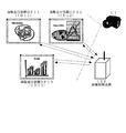
図14は、画像表示装置とコンテンツウインドウとの関係を示す図である。
1. 図14(1)に示すように、画像表示装置DP11、DP12と各コンテンツウインドウの表示を対応させて表示する場合であって、各画像表示装置DP11、DP12の上下左右と画像表示ウインドウの上下左右とを、一致させ、固定して表示する。各画像表示装置DP11、DP12の位置に関わらずに、表示内容は、画像表示装置DP11、DP12の識別子ID11、ID12のみで決定される。
FIG. 14 is a diagram illustrating the relationship between the image display device and the content window.
1. As shown in FIG. 14A, when the image display devices DP11 and DP12 are displayed in correspondence with the display of each content window, the image display devices DP11 and DP12 are vertically and horizontally and vertically and horizontally and horizontally. Are matched and fixed and displayed. Regardless of the position of each image display device DP11, DP12, the display content is determined only by the identifiers ID11, ID12 of the image display devices DP11, DP12.
全ての画像表示装置DP11、DP12に、同一の画像表示を行なう場合も含まれる。この場合、画像表示装置DP11、DP12へ送信する表示画像は、その位置に関わらず固定であるので、画像処理部133が画像処理する必要はない。この場合、画像表示装置DP11、DP12のそれぞれの位置関係が変わったときに、表示画像を交換することが可能である。 The case where the same image display is performed on all the image display devices DP11 and DP12 is also included. In this case, the display image to be transmitted to the image display devices DP11 and DP12 is fixed regardless of the position thereof, so the image processing unit 133 does not need to perform image processing. In this case, it is possible to exchange display images when the positional relationship between the image display devices DP11 and DP12 changes.
たとえば、右から左に向かって、画像表示装置DP11、DP12、DP13の並びが、画像表示装置DP11、DP13、DP12と変わった場合、画像表示装置DP12に表示していた表示画像と、画像表示装置DP13に表示していた表示画像とを交換することによって、表示画像の内容の連続性が保たれる場合がある。もちろん、画像表示装置の場所に関わらず、同じ画像を表示し続ける場合もある。
2. 図14(2)に示すように、複数の画像表示装置DP11、DP12、DP13、DP14を縦横に整列し、シームレスなコンテンツ画像を大画面で表示することができ、迫力のある大画面表示装置として用いることができる。この場合、画像表示装置DP11、DP12は、無線によって画像制御装置130と接続しているので、配線は不要であり、画像表示装置DP11〜DP14の位置によって自動で最適な画像を表示するので、配置が極めて容易である。この場合、画像表示装置DP11〜DP14のそれぞれは、大画面表示の画像(x、y)に対して平行に(kx、ky)だけシフトして配置されるので、画像表示装置DP11〜DP14のそれぞれにおける表示画像の座標は、(x−kx、y−ky)である。
3. 図14(3)に示すように、各画像表示装置DP11、DP12は、仮想の大画面映像の一部を表示し、画像表示装置DP11、DP12の位置や向きに応じて、仮想の大画面映像が崩れないように、画像表示装置DP11、DP12上に表示する映像は変化する。つまり、画像表示装置DP11、DP12を移動させると、その位置に応じて、画像が変化し、仮想の画像の一部を表示する窓のように機能する。
For example, when the arrangement of the image display devices DP11, DP12, DP13 changes from the right to the left as the image display devices DP11, DP13, DP12, the display image displayed on the image display device DP12, and the image display device By exchanging with the display image displayed on the
2. As shown in FIG. 14 (2), a plurality of image display devices DP11, DP12, DP13, and DP14 are arranged vertically and horizontally so that seamless content images can be displayed on a large screen, and as a powerful large screen display device. Can be used. In this case, since the image display devices DP11 and DP12 are wirelessly connected to the
3. As shown in FIG. 14 (3), each of the image display devices DP11 and DP12 displays a part of the virtual large screen image, and the virtual large screen image is displayed according to the position and orientation of the image display devices DP11 and DP12. The video displayed on the image display devices DP11 and DP12 changes so that the image does not collapse. That is, when the image display devices DP11 and DP12 are moved, the image changes according to the position, and functions as a window that displays a part of the virtual image.
これを実現するためには、仮想の表示画像の座標と、画像表示装置DP11、DP12上の座標とを、その相対位置関係において変換する。たとえば、仮想の表示画像の左下を基準にした場合における仮想の表示画像の画素の座標を(x、y)とし、画像表示装置DP11、DP12の左下の位置が、仮想の表示画像に対して、(kx、ky)だけ移動し、θだけ傾くとすると、画像表示装置DP11、DP12における表示画像の画素の座標(X,Y)に表示すべき表示画像の座標(x、y)は、以下の通りである。
X=(x−kx)cosθ+(y−ky)sinθ
Y=(y−ky)cosθ−(x−kx)sinθ
また、表示方式は上記1〜3に限られるものではなく、これらの組合せ等が任意に選択される。
In order to realize this, the coordinates of the virtual display image and the coordinates on the image display devices DP11 and DP12 are converted in the relative positional relationship. For example, the coordinate of the pixel of the virtual display image when the lower left of the virtual display image is used as a reference is (x, y), and the lower left position of the image display devices DP11 and DP12 is relative to the virtual display image. If it moves by (k x , k y ) and tilts by θ, the coordinates (x, y) of the display image to be displayed at the coordinates (X, Y) of the pixels of the display image in the image display devices DP11, DP12 are It is as follows.
X = (x−k x ) cos θ + (y−k y ) sin θ
Y = (y−k y ) cos θ− (x−k x ) sin θ
Further, the display method is not limited to the above 1 to 3, and a combination thereof is arbitrarily selected.
画像制御装置130から、画像表示装置DP11、DP12へ画像を伝送する方法については、無線方式の移動体通信による。
A method of transmitting an image from the
複数の画像表示装置DP11、DP12への伝送は、各識別子ID11、ID12に対応して、周波数分割多重方式、時間分割多重方式、符号分割多重方式等による同時に各映像信号に合わせて、複数の画像表示装置DP11、DP12へ伝送する。 Transmission to the plurality of image display devices DP11 and DP12 corresponds to each identifier ID11 and ID12, and a plurality of images are simultaneously matched to each video signal by frequency division multiplexing, time division multiplexing, code division multiplexing, or the like. The data is transmitted to the display devices DP11 and DP12.
画像表示装置DP11、DP12には、デジタイザ、またはスイッチ等が設けられ、所望の動作を、画像表示装置DP11、DP12側から制御することができるようになっていてもよい。 The image display devices DP11 and DP12 may be provided with a digitizer, a switch, or the like so that a desired operation can be controlled from the image display devices DP11 and DP12 side.
図15は、画像表示システム300における表示の一例を模式的に示す図である。 FIG. 15 is a diagram schematically illustrating an example of display in the image display system 300.
4台の画像表示装置DP11〜DP14を有する画像表示システム300であり、4台をタイリングして大画面表示している例である。画像表示システム300の表示においては、左下の画像表示装置DP13の表示部の左下と、大画面の表示画像の左下とを一致させている。このように多数のフラットパネルディスプレイをタイリングし、壁面に沿って設置することによって、壁面一面の画像表示を行なうことができる。 This is an example of an image display system 300 having four image display devices DP11 to DP14, in which four devices are tiled and displayed on a large screen. In the display of the image display system 300, the lower left of the display unit of the lower left image display device DP13 and the lower left of the display image on the large screen are matched. Thus, by tiling a large number of flat panel displays and installing them along the wall surface, it is possible to display an image of the entire wall surface.
また、さらに5台の画像表示装置を追加し、縦3台、横3台、合計9台に拡張し、表示モードを選択することによって、上記9台のタイリングディスプレイシステムに大画面表示することもできる。この際、仮想の画像を拡大し、上記9台の画像表示装置の位置に対応する画像を再構成すればよい。 In addition, 5 image display devices are added, and the display is expanded to 9 in total, 3 in the vertical direction and 3 in the horizontal direction, and the display mode is selected to display a large screen on the 9 tiling display systems. You can also. At this time, the virtual image may be enlarged and images corresponding to the positions of the nine image display devices may be reconstructed.
図16は、タイリングされた4台の画像表示装置DP11〜DP14を有する画像表示システム300を構成する画像表示装置DP11を、大画面の中央部辺りへ移動させた例を示す図である。 FIG. 16 is a diagram illustrating an example in which the image display device DP11 constituting the image display system 300 including the four image display devices DP11 to DP14 that are tiled is moved to the center of the large screen.
この場合、画像表示装置DP11へ表示する表示画像は、画像表示装置DP11の位置が移動することに合わせて、リアルタイムにフィードバックがかかり、あたかも画像表示装置DP11が、仮想の大画面表示の一部を表示する窓のように作用する。 In this case, the display image to be displayed on the image display device DP11 is fed back in real time as the position of the image display device DP11 moves, as if the image display device DP11 is part of the virtual large screen display. Acts like a window to display.
図17は、画像表示システム300を構成する3台の画像表示装置DP11、DP12、DP13が、互いに異なる表示画像を表示している例を示す図である。 FIG. 17 is a diagram illustrating an example in which three image display devices DP11, DP12, and DP13 configuring the image display system 300 display different display images.
この場合、表示装置の位置に関わらず、表示内容と画像表示装置DP11、DP12、DP13とを、一対一に対応させ、画像変換を行なわない。 In this case, regardless of the position of the display device, the display content and the image display devices DP11, DP12, DP13 are made to correspond one-to-one, and image conversion is not performed.
図15、図16、図17に関しては、画像表示システム300の画像表示方法の一例であり、複数の画像表示装置のうちの数枚の画像表示装置によって、大画面映像表示を行ない、残りの数枚の画像表示装置が、互いに異なる表示画像を表示するようにしてもよい。
15, 16, and 17 show an example of an image display method of the image display system 300, and a large screen image is displayed by several image display devices among a plurality of image display devices, and the remaining number of images is displayed. The image display devices may display different display images.
本発明の実施例6は、メモリ性のある画像表示装置DP11、DP12を使用する実施例である。 The sixth embodiment of the present invention is an embodiment using the image display devices DP11 and DP12 having a memory property.
画像表示装置DP11、DP12は、メモリ性をもつペーパーライクディスプレイであり、一例として電気泳動方式で微粒子が移動することによって、白黒表示やカラー表示を行なう。この場合、表示の書き換え時以外は、電力を必要としないので、画像表示装置DP11、DP12の省電力に有効である。 The image display devices DP11 and DP12 are paper-like displays having a memory property. For example, the image display devices DP11 and DP12 perform black-and-white display and color display by moving fine particles by electrophoresis. In this case, power is not required except when the display is rewritten, which is effective for power saving of the image display devices DP11 and DP12.
特に、電子ブック、ビジネス用途のテキスト中心の書類、広告看板、ポスター等の用途に適している。また、画像表示システム300では、複数の静止画をそれぞれ表示する画像表示装置DP11、DP12からなるシステムであり、複数枚の画像表示を用いる画像表示システムに最適であり、従来、複数枚の紙を広げて、共同作業や会議をするような場合に有効である。
In particular, it is suitable for applications such as electronic books, text-centric documents for business use, advertising signs, posters, and the like. The image display system 300 is a system including image display devices DP11 and DP12 that respectively display a plurality of still images, and is optimal for an image display system that uses a plurality of image displays. Conventionally, a plurality of sheets of paper are used. It is effective for expanding and collaborating and meeting.
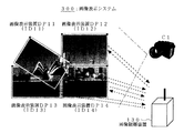
図18は、本発明の実施例7である画像表示システム400に使用されている画像表示装置DP13、DP14を示す図である。
FIG. 18 is a diagram showing the image display devices DP13 and DP14 used in the image display system 400 that is
画像表示装置DP13は、互いに直交する2つの基準線BL11、BL12を有し、画像表示装置DP14は、互いに直交する2つの基準線BL21、BL22を有する。 The image display device DP13 has two reference lines BL11 and BL12 orthogonal to each other, and the image display device DP14 has two reference lines BL21 and BL22 orthogonal to each other.
互いに直交する基準線BL11、BL12を用いることによって、撮像時の画像表示装置DP13の歪みをより正確に補正することができる。つまり、画像表示装置DP13の上空斜め方向から撮像した場合、画像表示装置DP13に、一般に台形歪みが生じるが、これを、予め既知である直交する基準線BL11、BL12を用いることによって、画像表示装置DP13の補正ができる。 By using the reference lines BL11 and BL12 orthogonal to each other, the distortion of the image display device DP13 at the time of imaging can be corrected more accurately. That is, when the image display device DP13 is picked up from an oblique direction above the image display device DP13, a trapezoidal distortion is generally generated in the image display device DP13. This is obtained by using the orthogonal reference lines BL11 and BL12 that are known in advance. DP13 can be corrected.
また、基準線BL11、BL12として画像表示部の境界線を用いることによって、画像表示装置DP13上に基準線BL1、BL2を設ける必要がなくなり、狭額縁の構造を可能にする。 Further, by using the boundary lines of the image display unit as the reference lines BL11 and BL12, it is not necessary to provide the reference lines BL1 and BL2 on the image display device DP13, and a narrow frame structure is possible.
画像表示装置DP14における動作は、画像表示装置DP13における上記動作と同様である。
The operation in the image display device DP14 is the same as the operation in the image display device DP13.
本発明の実施例8は、実施例4の第2の方式において、撮影部C1を使って位置検出する実施例であり、つまり画像表示システム300において、画像表示装置が、表示画像を再構築する実施例である。 The eighth embodiment of the present invention is an embodiment in which the position is detected using the photographing unit C1 in the second method of the fourth embodiment, that is, in the image display system 300, the image display device reconstructs the display image. This is an example.
図19は、画像表示システム300において、画像表示装置が、表示画像の再構築を行なう動作を示すフローチャートである。 FIG. 19 is a flowchart illustrating an operation in which the image display apparatus reconstructs a display image in the image display system 300.
まず、画像表示装置の位置情報に合わせて、画像表示するのであれば(S31)、画像表示装置を位置検出する場合、画像制御装置130の撮像部C1が、全ての画像表示装置を撮像し(S32)、画像制御装置130が、画像表示装置の位置を算出した後に(S33)、画像制御装置130は、各画像表示装置の位置に応じて最適な表示画像を換算計算し、再構築をする(S34)。
First, if an image is displayed in accordance with the position information of the image display device (S31), when detecting the position of the image display device, the imaging unit C1 of the
そして、画像制御装置130は、元の表示画像をブロードキャスト送信し、全ての画像表示装置が、各位置に対応した表示画像を再構築し(S45)、表示する(S46)。必要があれば、画像表示装置の位置を変更する(S47)。
Then, the
画像制御装置130は、画像処理機能を必要としないので、画像表示装置の数が多い場合等、画像処理の負荷と画像伝送の負荷とを軽減できるので、特に、画像表示装置の数が多い場合に適している。また、画像表示装置を、縦横に整列させて用いるタイリングの大画面表示に適している。
Since the
100、200、300…画像表示システム、
DP1〜DP4、DP11〜DP14…画像表示装置、
30、130…画像制御装置、
C1…撮像部、
BL1、BL2、BL11〜BL14…基準線。
100, 200, 300 ... image display system,
DP1 to DP4, DP11 to DP14... Image display device,
30, 130 ... Image control device,
C1 ... imaging unit,
BL1, BL2, BL11 to BL14... Reference line.
Claims (10)
上記複数の画像表示装置のそれぞれの位置を検出し、所定の表示画像を上記画像表示装置に送信する画像制御装置と;
を有し、上記画像表示装置は、自己の位置情報に対応する表示画像を表示することを特徴とする画像表示システム。 A plurality of image display devices having a communication function;
An image control device for detecting a position of each of the plurality of image display devices and transmitting a predetermined display image to the image display device;
And the image display device displays a display image corresponding to its own position information.
上記画像制御装置は、上記複数の画像表示装置のそれぞれまでの距離と方向とを測定することによって、上記画像表示装置の位置を検出することを特徴とする画像表示システム。 In claim 1,
The image control system detects the position of the image display device by measuring a distance and a direction to each of the plurality of image display devices.
上記画像制御装置は、上記複数の画像表示装置のそれぞれの位置を検出するために、空間的に離された少なくとも3点の制御基準点を具備し、上記画像表示装置は、画像表示面に水平な方向において空間的に離れた少なくとも2点の表示基準点を具備し、上記画像制御装置の上記制御基準点と、上記画像表示装置の上記表示基準点との距離を測定することによって、上記画像表示装置の位置を検出することを特徴とする画像表示システム。 In claim 2,
The image control device includes at least three control reference points that are spatially separated in order to detect the position of each of the plurality of image display devices, and the image display device is horizontal to the image display surface. And measuring the distance between the control reference point of the image control device and the display reference point of the image display device by providing at least two display reference points spatially separated in a certain direction. An image display system for detecting a position of a display device.
上記複数の画像表示装置のうちの1つの画像表示装置が、マスタ画像表示装置であり、上記複数の画像表示装置のうちの残りの画像表示装置が、スレーブ画像表示装置であり、上記マスタ画像表示装置が、上記マスタ画像表示装置から上記スレーブ画像表示装置までの距離と方向とを測定することによって、上記複数の画像表示装置のそれぞれの位置を検出することを特徴とする画像表示システム。 In claim 1,
One image display device of the plurality of image display devices is a master image display device, and the remaining image display devices of the plurality of image display devices are slave image display devices, and the master image display device An image display system, wherein the apparatus detects a position of each of the plurality of image display devices by measuring a distance and a direction from the master image display device to the slave image display device.
上記画像制御装置は、上記画像表示装置の位置に対応する表示画像を作成し、上記画像表示装置に伝送し、上記画像表示装置は、受信した表示画像を表示することを特徴とする画像表示システム。 In claim 1,
The image control device creates a display image corresponding to the position of the image display device, transmits the display image to the image display device, and the image display device displays the received display image. .
上記画像制御装置は、表示画像を上記画像表示装置に伝送し、上記画像表示装置はその位置に対応する表示画像を作成し、表示することを特徴とする画像表示システム。 In claim 1,
An image display system, wherein the image control device transmits a display image to the image display device, and the image display device creates and displays a display image corresponding to the position.
上記画像表示装置の位置を変化させるとともに、上記画像表示装置の各位置情報を更新し、この更新した位置情報に対応する表示画像を再表示することを特徴とする画像表示システム。 In claim 1,
An image display system characterized by changing the position of the image display device, updating each position information of the image display device, and redisplaying a display image corresponding to the updated position information.
上記画像制御装置は、上記複数の画像表示装置のそれぞれを撮影することによって、上記複数の画像表示装置のそれぞれの位置を検出することを特徴とする画像表示システム。 In claim 1,
The image control system detects each position of the plurality of image display devices by photographing each of the plurality of image display devices.
上記画像表示装置は、上記画像表示装置の位置情報を算出するための既知である基準線を少なくとも1本具備し、上記画像制御装置は、上記画像表示装置上の上記基準線を用いて画像認識することによって、各画像表示装置の相対位置を算出することを特徴とする画像表示システム。 In claim 8,
The image display device includes at least one known reference line for calculating position information of the image display device, and the image control device recognizes an image using the reference line on the image display device. To calculate the relative position of each image display device.
上記複数の画像表示装置のそれぞれの位置を検出し、該検出した位置に応じた表示画像を各画像表示装置において表示することを特徴とする画像表示方法。 In an image display method for displaying an image on a plurality of image display devices,
An image display method, comprising: detecting a position of each of the plurality of image display devices; and displaying a display image corresponding to the detected position on each image display device.
Priority Applications (1)
| Application Number | Priority Date | Filing Date | Title |
|---|---|---|---|
| JP2003414192A JP2005173291A (en) | 2003-12-12 | 2003-12-12 | Image display system and image display method |
Applications Claiming Priority (1)
| Application Number | Priority Date | Filing Date | Title |
|---|---|---|---|
| JP2003414192A JP2005173291A (en) | 2003-12-12 | 2003-12-12 | Image display system and image display method |
Publications (1)
| Publication Number | Publication Date |
|---|---|
| JP2005173291A true JP2005173291A (en) | 2005-06-30 |
Family
ID=34734066
Family Applications (1)
| Application Number | Title | Priority Date | Filing Date |
|---|---|---|---|
| JP2003414192A Pending JP2005173291A (en) | 2003-12-12 | 2003-12-12 | Image display system and image display method |
Country Status (1)
| Country | Link |
|---|---|
| JP (1) | JP2005173291A (en) |
Cited By (25)
| Publication number | Priority date | Publication date | Assignee | Title |
|---|---|---|---|---|
| JP2007264141A (en) * | 2006-03-27 | 2007-10-11 | National Institute Of Advanced Industrial & Technology | Video display device |
| JP2009288453A (en) * | 2008-05-28 | 2009-12-10 | Canon Inc | Display control system and display control method |
| JP2010026328A (en) * | 2008-07-22 | 2010-02-04 | Canon Inc | Display system and display method |
| JP2011022862A (en) * | 2009-07-16 | 2011-02-03 | Sharp Corp | Display control unit, display control system, and computer program |
| JP2011022391A (en) * | 2009-07-16 | 2011-02-03 | Nec Lcd Technologies Ltd | Image display device and driving method for the same |
| JP2011048431A (en) * | 2009-08-25 | 2011-03-10 | Brother Industries Ltd | Image display system, image processing unit, and electronic paper sheet |
| JP2011237532A (en) * | 2010-05-07 | 2011-11-24 | Nec Casio Mobile Communications Ltd | Terminal device, terminal communication system and program |
| JP2012014103A (en) * | 2010-07-05 | 2012-01-19 | Mitsubishi Electric Corp | Large-sized video display device |
| JP2012098835A (en) * | 2010-10-29 | 2012-05-24 | Casio Comput Co Ltd | Image display device and program |
| JP2012133069A (en) * | 2010-12-21 | 2012-07-12 | Yahoo Japan Corp | Multi-display system and control method thereof |
| JP2012242793A (en) * | 2011-05-24 | 2012-12-10 | Nikon Corp | Display system and electronic apparatus |
| JP2012256068A (en) * | 2012-08-17 | 2012-12-27 | National Institute Of Advanced Industrial & Technology | Image display device |
| JP2013064923A (en) * | 2011-09-20 | 2013-04-11 | Toyota Motor Corp | Multi-display control device |
| US8451191B2 (en) | 2008-07-22 | 2013-05-28 | Canon Kabushiki Kaisha | Display system, display method, information processing apparatus, and computer-readable storage medium |
| WO2013108362A1 (en) * | 2012-01-17 | 2013-07-25 | 株式会社レイトロン | Display unit and display system |
| JP2013182089A (en) * | 2012-02-29 | 2013-09-12 | Toshiba Corp | Display control apparatus and display control method |
| CN104392667A (en) * | 2014-11-17 | 2015-03-04 | 苏州佳世达电通有限公司 | Display device positioning method |
| JP2015056718A (en) * | 2013-09-11 | 2015-03-23 | 株式会社リコー | Projection system, projection apparatus and method |
| JPWO2013108362A1 (en) * | 2012-01-17 | 2015-05-11 | 株式会社レイトロン | Display and display system |
| JP2015097090A (en) * | 2014-11-26 | 2015-05-21 | 日本電気株式会社 | Portable terminal system, control method of portable terminal system, and control program of portable terminal system |
| JP2016095502A (en) * | 2014-11-11 | 2016-05-26 | 株式会社半導体エネルギー研究所 | Display system, display device |
| JP2017522655A (en) * | 2014-06-12 | 2017-08-10 | ソニー株式会社 | Handover of input from the first device to the second device |
| WO2018179730A1 (en) * | 2017-03-30 | 2018-10-04 | 富士通株式会社 | Information processing system, information processing device and information processing method |
| JP2023548800A (en) * | 2020-11-03 | 2023-11-21 | インターナショナル・ビジネス・マシーンズ・コーポレーション | Determining the position of peripheral devices relative to the primary display |
| JP2024098613A (en) * | 2023-01-11 | 2024-07-24 | 富士通クライアントコンピューティング株式会社 | Information Processing System |
-
2003
- 2003-12-12 JP JP2003414192A patent/JP2005173291A/en active Pending
Cited By (33)
| Publication number | Priority date | Publication date | Assignee | Title |
|---|---|---|---|---|
| JP2007264141A (en) * | 2006-03-27 | 2007-10-11 | National Institute Of Advanced Industrial & Technology | Video display device |
| JP2009288453A (en) * | 2008-05-28 | 2009-12-10 | Canon Inc | Display control system and display control method |
| US8451191B2 (en) | 2008-07-22 | 2013-05-28 | Canon Kabushiki Kaisha | Display system, display method, information processing apparatus, and computer-readable storage medium |
| JP2010026328A (en) * | 2008-07-22 | 2010-02-04 | Canon Inc | Display system and display method |
| JP2011022862A (en) * | 2009-07-16 | 2011-02-03 | Sharp Corp | Display control unit, display control system, and computer program |
| JP2011022391A (en) * | 2009-07-16 | 2011-02-03 | Nec Lcd Technologies Ltd | Image display device and driving method for the same |
| US8736545B2 (en) | 2009-07-16 | 2014-05-27 | Nlt Technologies, Ltd. | Image display device and driving method for the same |
| JP2011048431A (en) * | 2009-08-25 | 2011-03-10 | Brother Industries Ltd | Image display system, image processing unit, and electronic paper sheet |
| JP2011237532A (en) * | 2010-05-07 | 2011-11-24 | Nec Casio Mobile Communications Ltd | Terminal device, terminal communication system and program |
| JP2012014103A (en) * | 2010-07-05 | 2012-01-19 | Mitsubishi Electric Corp | Large-sized video display device |
| JP2012098835A (en) * | 2010-10-29 | 2012-05-24 | Casio Comput Co Ltd | Image display device and program |
| JP2012133069A (en) * | 2010-12-21 | 2012-07-12 | Yahoo Japan Corp | Multi-display system and control method thereof |
| JP2012242793A (en) * | 2011-05-24 | 2012-12-10 | Nikon Corp | Display system and electronic apparatus |
| JP2013064923A (en) * | 2011-09-20 | 2013-04-11 | Toyota Motor Corp | Multi-display control device |
| JPWO2013108362A1 (en) * | 2012-01-17 | 2015-05-11 | 株式会社レイトロン | Display and display system |
| WO2013108362A1 (en) * | 2012-01-17 | 2013-07-25 | 株式会社レイトロン | Display unit and display system |
| CN104025182A (en) * | 2012-01-17 | 2014-09-03 | 株式会社雷特龙 | Display unit and display system |
| JP2013182089A (en) * | 2012-02-29 | 2013-09-12 | Toshiba Corp | Display control apparatus and display control method |
| JP2012256068A (en) * | 2012-08-17 | 2012-12-27 | National Institute Of Advanced Industrial & Technology | Image display device |
| JP2015056718A (en) * | 2013-09-11 | 2015-03-23 | 株式会社リコー | Projection system, projection apparatus and method |
| JP2017522655A (en) * | 2014-06-12 | 2017-08-10 | ソニー株式会社 | Handover of input from the first device to the second device |
| US10719284B2 (en) | 2014-11-11 | 2020-07-21 | Semiconductor Energy Laboratory Co., Ltd. | Display system and display device |
| JP2016095502A (en) * | 2014-11-11 | 2016-05-26 | 株式会社半導体エネルギー研究所 | Display system, display device |
| JP2023133384A (en) * | 2014-11-11 | 2023-09-22 | 株式会社半導体エネルギー研究所 | display device |
| US11216138B2 (en) | 2014-11-11 | 2022-01-04 | Semiconductor Energy Laboratory Co., Ltd. | Display system and display device |
| CN104392667A (en) * | 2014-11-17 | 2015-03-04 | 苏州佳世达电通有限公司 | Display device positioning method |
| CN104392667B (en) * | 2014-11-17 | 2016-09-07 | 苏州佳世达电通有限公司 | Display device localization method |
| JP2015097090A (en) * | 2014-11-26 | 2015-05-21 | 日本電気株式会社 | Portable terminal system, control method of portable terminal system, and control program of portable terminal system |
| JP2018169583A (en) * | 2017-03-30 | 2018-11-01 | 富士通株式会社 | Information processing system, information processing apparatus, and information processing method |
| WO2018179730A1 (en) * | 2017-03-30 | 2018-10-04 | 富士通株式会社 | Information processing system, information processing device and information processing method |
| JP2023548800A (en) * | 2020-11-03 | 2023-11-21 | インターナショナル・ビジネス・マシーンズ・コーポレーション | Determining the position of peripheral devices relative to the primary display |
| JP7721238B2 (en) | 2020-11-03 | 2025-08-12 | インターナショナル・ビジネス・マシーンズ・コーポレーション | Determining the position of a peripheral device relative to a primary display |
| JP2024098613A (en) * | 2023-01-11 | 2024-07-24 | 富士通クライアントコンピューティング株式会社 | Information Processing System |
Similar Documents
| Publication | Publication Date | Title |
|---|---|---|
| JP2005173291A (en) | Image display system and image display method | |
| US20090244001A1 (en) | Back plate, display, display system, method of supplying an electric power, and display method | |
| JP5552804B2 (en) | Stereoscopic image display device, manufacturing method thereof, and stereoscopic image display method | |
| CN101903860A (en) | Method for clustering displays of a display device | |
| JP2006065599A (en) | Display device, communication system and method | |
| US20110069157A1 (en) | Three-dimensional image display device, method of manufacturing the same, and three-dimensional image display method | |
| CN102279513A (en) | Stereoscopic image display device and stereoscopic image display method | |
| CN111670548B (en) | Provide a communication system, a display control device, and a communication terminal that supplement the downlink | |
| JP2004198450A (en) | Image display system | |
| JP2014041370A (en) | Display device | |
| CN110111721B (en) | Display device and splicing structure thereof | |
| WO2012176628A1 (en) | Imaging device and wireless system | |
| TW201335673A (en) | Displays | |
| JP2011154581A (en) | Exhibition visiting support system and information display device | |
| JP4930115B2 (en) | Image display system | |
| US8743092B2 (en) | Display apparatus that determines a pointing position of a pointing device and method thereof | |
| US20140071159A1 (en) | Method and Apparatus For Providing a User Interface For a File System | |
| JP4401465B2 (en) | Display device and image display method | |
| US11650779B2 (en) | Infinitely expandable display apparatus and driving method thereof | |
| KR102674539B1 (en) | Display device and method thereof | |
| JP2024509648A (en) | Display driving integrated circuits, displays and electronic equipment | |
| JP4134157B2 (en) | Display device | |
| WO2020062876A1 (en) | Service provision method and system based on optical label | |
| CN103248643A (en) | File receiving display method and system | |
| KR101904746B1 (en) | The apparatus for display a frontview moving picture in digital signage |