JP2012242793A - Display system and electronic apparatus - Google Patents
Display system and electronic apparatus Download PDFInfo
- Publication number
- JP2012242793A JP2012242793A JP2011116082A JP2011116082A JP2012242793A JP 2012242793 A JP2012242793 A JP 2012242793A JP 2011116082 A JP2011116082 A JP 2011116082A JP 2011116082 A JP2011116082 A JP 2011116082A JP 2012242793 A JP2012242793 A JP 2012242793A
- Authority
- JP
- Japan
- Prior art keywords
- electronic device
- positional relationship
- display
- unit
- control unit
- Prior art date
- Legal status (The legal status is an assumption and is not a legal conclusion. Google has not performed a legal analysis and makes no representation as to the accuracy of the status listed.)
- Pending
Links
Images


Abstract
Description
本発明は、表示システム及び電子機器に関するものである。 The present invention relates to a display system and an electronic device.
従来、同一画像の各領域を複数の表示部に表示させる技術として、同一画像を複数の領域に分割し、各領域の画像情報を複数の表示部を備える表示装置に出力するものが開示されている(例えば、特許文献1参照)。 Conventionally, as a technique for displaying each area of the same image on a plurality of display units, a technique for dividing the same image into a plurality of areas and outputting image information of each area to a display device including a plurality of display units has been disclosed. (For example, refer to Patent Document 1).
しかしながら、引用文献1の技術の場合、表示装置以外にサーバ、カメラなどの装置が必要であるという問題がある。また、引用文献1の技術の場合、表示部同士の距離に制限があるため携帯機器などに応用できないという問題がある。
本発明は、複数の携帯機器の表示部に、携帯機器以外の装置を用いることなく、同一画像の各領域を表示させる技術を提供する。
However, the technique of the cited
The present invention provides a technique for displaying each region of the same image on a display unit of a plurality of portable devices without using a device other than the portable device.
上記問題を解決するために、本発明の一態様である表示システムは、表示部を有する複数の電子機器から構成され、前記電子機器の夫々が同一画像の夫々異なる一部の領域を表示する表示システムであって、各電子機器は、前記夫々の表示部を制御する制御部と、該表示システムを構成する他の電子機器の位置情報を取得する取得部とを備え、前記制御部は、前記取得部が取得した前記他の電子機器の位置情報に基づいて自身と前記他の電子機器との位置関係を算出し、前記位置関係に基づいて自身が表示する前記一部の領域を決定し、前記一部の領域を前記表示部の全体に表示するよう制御することを特徴とする。 In order to solve the above problem, a display system which is one embodiment of the present invention includes a plurality of electronic devices each having a display unit, and each of the electronic devices displays a different partial area of the same image. Each electronic device includes a control unit that controls the respective display units, and an acquisition unit that acquires position information of other electronic devices that constitute the display system. Calculate the positional relationship between itself and the other electronic device based on the positional information of the other electronic device acquired by the acquisition unit, determine the partial area displayed by itself based on the positional relationship, Control is performed so that the partial area is displayed on the entire display unit.
上記表示システムにおいて、前記制御部は、前記位置関係の算出として、自身を含む該表示システムを構成する複数の電子機器の位置関係を表現するマップを生成し、前記マップにおける自身の位置に相当する、画像の全領域における前記一部の領域を決定するようにしてもよい。 In the display system, the control unit generates a map representing the positional relationship between a plurality of electronic devices that constitute the display system including the display system, and corresponds to the position of the electronic device in the map. The partial area in the entire area of the image may be determined.
上記表示システムにおいて、該表示システムを構成する電子機器の夫々が夫々の前記一部の領域を表示している場合に、そのうちの一の電子機器の表示ができなくなったときは、前記一の電子機器を除く各電子機器の前記制御部は、前記一の電子機器が表示していた前記一部の領域が、前記一の電子機器を除く各電子機器の表示部に表示されるように画像を変形し、変形後の画像において前記一部の領域を再決定するようにしてもよい。 In the display system, when each of the electronic devices constituting the display system displays the partial area, when the display of one of the electronic devices becomes impossible, the one electronic device The control unit of each electronic device excluding the device displays an image so that the partial area displayed by the one electronic device is displayed on a display unit of each electronic device excluding the one electronic device. The part of the area may be redetermined in the deformed image.
上記表示システムにおいて、前記取得部は、前記他の電子機器の位置情報を他の電子機器と相互に通信して取得する通信部、又は、前記他の電子機器の位置情報を前記他の電子機器の位置を測定して取得する測位部であってもよい。 In the display system, the acquisition unit communicates and acquires position information of the other electronic device with the other electronic device, or position information of the other electronic device. The positioning part which measures and acquires the position of may be sufficient.
上記問題を解決するために、本発明の他の態様である電子機器は、表示部と、前記表示部を制御する制御部と、他の電子機器の位置情報を取得する取得部とを備え、前記制御部は、前記取得部が取得した他の電子機器の位置情報に基づいて自身と他の電子機器との位置関係を算出し、前記位置関係に基づいて画像の一部の領域を決定し、前記画像の一部の領域を前記表示部の全体に表示するよう制御することを特徴とする。 In order to solve the above problem, an electronic apparatus according to another aspect of the present invention includes a display unit, a control unit that controls the display unit, and an acquisition unit that acquires position information of the other electronic device. The control unit calculates a positional relationship between itself and another electronic device based on the positional information of the other electronic device acquired by the acquiring unit, and determines a partial region of the image based on the positional relationship. And controlling to display a partial region of the image on the entire display unit.
本発明によれば、複数の電子機器(携帯機器)の表示部に、電子機器以外の装置を用いることなく、同一画像の各領域を表示させることができる。更に、本発明によれば、複数の電子機器は対等な関係であるため、ホスト、スレイブなどの役割を予め設定する必要がなく、複数の電子機器の並び順も自由に変えることもできる。 ADVANTAGE OF THE INVENTION According to this invention, each area | region of the same image can be displayed on the display part of a some electronic device (mobile device), without using apparatuses other than an electronic device. Furthermore, according to the present invention, since a plurality of electronic devices have an equal relationship, it is not necessary to set roles such as a host and a slave in advance, and the arrangement order of the plurality of electronic devices can be freely changed.
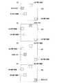
以下、図面を参照しながら本発明の実施形態について説明する。図1は、本発明の実施形態による表示システム1、及び、表示システム1を構成する電子機器10を説明するための説明図である。
Hereinafter, embodiments of the present invention will be described with reference to the drawings. FIG. 1 is an explanatory diagram for explaining a
表示システム1は、複数の電子機器10から構成されている。例えば、表示システム1は、図1(a)に示すように、電子機器10a、10b、10c、10dの4台から構成される。各電子機器10は、図1(b)のような携帯型の機器であって、図1(c)に示すように、取得部12、制御部14、表示部16及び記憶部18を備える。
The
記憶部18は、表示部16に表示する画像を記憶する。各電子機器10は、1つ以上の同一画像(共通の画像)を記憶部18に記憶する。各電子機器10は、電子機器10間の通信によって共有された画像、又は、各電子機器10の夫々に対して外部から送信された画像を同一画像として記憶部18に記憶する。
The
なお、電子機器10間の通信によって画像を共有する場合において、共有する画像は、例えば、ネットワークを介して、又は、記憶媒体を介して取得したものであってもよいし、非図示の撮像部によって撮像したものであってもよい。
In the case of sharing an image by communication between the
取得部12は、他の電子機器10の位置情報を取得する。上記位置情報は、表示システム1を構成する複数の電子機器10の所在の分布における自身の相対的な位置関係を把握するために用いられる。上記相対的な位置関係は、自身の位置の変化、及び、他の電子機器10の位置の変化に応じて変化するため、取得部12は、上記相対的な位置関係をリアルタイムに把握するため、定期的(周期的)に位置情報を取得する。取得部12による位置情報の取得には種々の態様が考えられる。
The
(第1の取得態様)
第1の取得態様は、取得部12が通信部として、位置情報を取得する態様である。取得部12(通信部)は、他の電子機器10と相互に通信し、他の電子機器10の位置情報を取得する。例えば、2つの方法が存在する。1つ目の方法は、各電子機器10がGPS機能(非図示)を備え、自身の位置情報を取得し、又は、携帯電話網のピコセル若しくは公衆無線LANのアクセスポイントなどの情報から自身の位置情報を取得し、夫々の位置情報を通信によって交換し、他の電子機器10の位置情報を取得するという方法である。なお、通信部による通信には、公衆無線LAN、携帯電話網などを利用する通信の他、赤外線通信などの近距離無線通信も含まれる。また、赤外線通信などによるアドホック通信の場合において、第1の電子機器10と第2の電子機器とが直接に通信不能な場合には、第3の電子機器(又は、第3、第4、…の電子機器)を経由して、夫々の位置情報を交換してもよい。2つ目の方法は、各電子機器10が筐体に発射/感受方向の異なる複数の通信部(送受信部)を備え、他の電子機器10から発射された信号を受信した通信部の筐体における位置、受信信号の強度から、他の電子機器10の位置情報を取得するという方法である。
(第2の取得態様)
第2の取得態様は、取得部12が他の電子機器10の測位を行う測位部として、位置情報を取得する態様である。例えば、各電子機器10が測位部としてレーザレーダーを備え、他の電子機器の位置情報を取得する。
(First acquisition mode)
The first acquisition mode is a mode in which the
(Second acquisition mode)
The second acquisition mode is a mode in which the
なお、電子機器10の夫々を識別する識別情報を位置情報若しくは発射信号に付加又は重畳させれば、位置情報から他の電子機器10の夫々を特定可能である。但し、電子機器10は、複数の電子機器10の所在の分布における自身の相対的な位置関係を把握しさえすればよく、他の電子機器10の個々を特定しなくてもよい。
If identification information for identifying each of the
制御部14は、同一画像の夫々異なる一部の領域を夫々の電子機器10の表示部16に表示する機能を実現する。具体的には、制御部14は、他の電子機器10の位置情報を取得部12から取得する。他の電子機器10の位置情報を取得した制御部14は、当該位置情報に基づいて自身と他の電子機器10との位置関係(表示システム1を構成する複数の電子機器10の所在の分布における自身の相対的な位置関係)を算出する。具体的には、制御部14は、上記位置関係の算出として、自身を含む複数の電子機器10の位置関係を表現するマップ(以下、「位置関係マップ」という)を生成する。
The
具体的には、制御部14は、電子機器10同士の距離を考慮(反映)しない位置関係マップを生成する。電子機器10同士の距離を考慮しない位置関係マップとは、複数の電子機器10を相対的な位置関係を維持しつつ、各電子機器10を表現する矩形を、上下、左右、又は上下左右に接して配置したときに、全電子機器10に係る全矩形に外接する大きな矩形によって表現されるマップである。
Specifically, the
図2は、電子機器10同士の距離を考慮しない位置関係マップの一例である。
例えば、図1(a)に示す電子機器10aの制御部14は、複数の電子機器10との相対的な位置関係において自身が略左上に位置すると認識し、図2(a)に示すような電子機器10同士の距離を考慮しない位置関係マップM1を生成する。なお、図2(a)の網掛部は、電子機器10aの制御部14が認識している自身の相対的な位置である。同様に、図1(a)に示す電子機器10bの制御部14は、複数の電子機器10との相対的な位置関係において自身が略右上に位置すると認識し、図2(b)に示すような位置関係マップM1を生成する。同様に、図1(a)に示す電子機器10cの制御部14は、複数の電子機器10との相対的な位置関係において自身が略左下に位置すると認識し、図2(c)に示すような位置関係マップM1を生成する。同様に、図1(a)に示す電子機器10dの制御部14は、複数の電子機器10との相対的な位置関係において自身が略右下に位置すると認識し、図2(d)に示すような位置関係マップM1を生成する。
FIG. 2 is an example of a positional relationship map that does not consider the distance between the
For example, the
また、制御部14は、電子機器10同士の距離を考慮しない位置関係マップに代えて、電子機器10同士の距離を考慮した位置関係マップを生成してもよい。電子機器10同士の距離を考慮した位置関係マップとは、複数の電子機器10を方向、距離を維持しつつ、各電子機器10を表現する矩形を配置したときに、全電子機器10に係る全矩形に外接する大きな矩形によって表現されるマップである。
Further, the
図3は、電子機器10同士の距離を考慮した位置関係マップの一例である。
例えば、図1(a)に示す電子機器10aの制御部14は、複数の電子機器10との相対的な位置関係において自身が略左上に位置すると認識し、図3(a)に示すような電子機器10同士の距離を考慮した位置関係マップM2を生成する。同様に、図1(a)に示す電子機器10bの制御部14は図3(b)に示すような位置関係マップM2を生成し、図1(a)に示す電子機器10cの制御部14は図3(c)に示すような位置関係マップM2を生成し、図1(a)に示す電子機器10dの制御部14は図3(d)に示すような位置関係マップM2を生成する。
FIG. 3 is an example of a positional relationship map in consideration of the distance between the
For example, the
制御部14は、位置関係を算出した場合、当該位置関係に基づいて、自身が表示するべき画像(同一画像)の一部の領域を担当領域として決定する。具体的には、位置関係マップを生成した制御部14は、当該位置関係マップにおける自身の位置に相当する、画像(同一画像)の全領域における一部の領域を担当領域として決定する。換言すれば、制御部14は、表示するべき画像(同一画像)に、位置関係マップの縦横比、サイズを変化させて重ねたときに、自身を示す矩形の位置に相当する画像上の領域を担当領域として決定する。
When calculating the positional relationship, the
図4は、電子機器10同士の距離を考慮しない位置関係マップを生成した場合の制御部14の制御を説明するための説明図である。図5は、電子機器10同士の距離を考慮した位置関係マップを生成した場合の制御部14の制御を説明するための説明図である。
例えば、図1(a)に示す電子機器10aの制御部14は、図2(a)に示す位置関係マップM1を生成した場合には、記憶部18から図4(a)に示す画像Pを読み出して、図2(a)に示す位置関係マップM1における自身の位置(左上)に相当する、画像Pの領域R1−1(図4(b)参照)を担当領域として決定する。同様に、図1(a)に示す電子機器10bの制御部14は、図2(b)に示す位置関係マップM1を生成した場合には、記憶部18から図4(a)に示す画像Pを読み出して、図2(b)に示す位置関係マップM1における自身の位置(右上)に相当する、画像Pの領域R1−2(図4(b)参照)を担当領域として決定する。同様に、図1(a)に示す電子機器10cの制御部14は、図2(c)に示す位置関係マップM1を生成した場合には、記憶部18から図4(a)に示す画像Pを読み出して、図2(c)に示す位置関係マップM1における自身の位置(左下)に相当する、画像Pの領域R1−3(図4(b)参照)を担当領域として決定する。同様に、図1(a)に示す電子機器10dの制御部14は、図2(d)に示す位置関係マップM1を生成した場合には、記憶部18から図4(a)に示す画像Pを読み出して、図2(d)に示す位置関係マップM1における自身の位置(右下)に相当する、画像Pの領域R1−4(図4(b)参照)を担当領域として決定する。
FIG. 4 is an explanatory diagram for explaining the control of the
For example, when the
なお、各電子機器10の記憶部18に複数の同一画像が記憶されている場合には、制御部14は、電子機器10間の通信によって共有された画像のうち最新のもの、又は、各電子機器10に対して外部から送信された画像のうちの最新のもの、又は、電子機器10間の通信によって指定された同一画像を、記憶部18から読み出してもよい。
When a plurality of identical images are stored in the
一方、例えば、図1(a)に示す電子機器10aの制御部14は、図3(a)に示す位置関係マップM2を生成した場合には、記憶部18から図5(a)に示す画像Pを読み出して、図3(a)に示す位置関係マップM2における自身の位置に相当する、画像Pの領域R2−1(図5(b)参照)を担当領域として決定する。同様に、図1(a)に示す電子機器10bの制御部14は、図3(b)に示す位置関係マップM2を生成した場合には、領域R2−2(図5(b)参照)を担当領域として決定する。同様に、図1(a)に示す電子機器10cの制御部14は、図3(c)に示す位置関係マップM2を生成した場合には、領域R2−3(図5(b)参照)を担当領域として決定する。同様に、図1(a)に示す電子機器10dの制御部14は、図3(d)に示す位置関係マップM2を生成した場合には、領域R2−4(図5(b)参照)を担当領域として決定する。
On the other hand, for example, when the
制御部14は、担当領域を決定した場合、担当領域を表示部16の全体に表示するよう制御する。表示部16は、制御部14の制御に従って画像の担当領域を表示する。
When determining the assigned area, the
例えば、図1(a)に示す電子機器10aの制御部14は、図4(b)に示す領域R1−1を担当領域として決定した場合には、図4(c)に示すように、表示部16の全体に、画像Pの領域R1−1が表示されるように制御する。同様に、図1(a)に示す電子機器10bの制御部14は、図4(b)に示す領域R1−2を担当領域として決定した場合には、図4(c)に示すように、表示部16の全体に、画像Pの領域R1−2が表示されるように制御する。同様に、図1(a)に示す電子機器10cの制御部14は、図4(b)に示す領域R1−3を担当領域として決定した場合には、図4(c)に示すように、表示部16の全体に、画像Pの領域R1−3が表示されるように制御する。同様に、図1(a)に示す電子機器10dの制御部14は、図4(b)に示す領域R1−4を担当領域として決定した場合には、図4(c)に示すように、表示部16の全体に、画像Pの領域R1−4が表示されるように制御する。
For example, when the
一方、例えば、図1(a)に示す電子機器10aの制御部14は、図5(b)に示す領域R2−1を担当領域として決定した場合には、図5(c)に示すように、表示部16の全体に、画像Pの領域R2−1が表示されるように制御する。同様に、図1(a)に示す電子機器10bの制御部14は、図5(b)に示す領域R2−2を担当領域として決定した場合には、図5(c)に示すように、表示部16の全体に、画像Pの領域R2−2が表示されるように制御する。同様に、図1(a)に示す電子機器10cの制御部14は、図5(b)に示す領域R2−3を担当領域として決定した場合には、図5(c)に示すように、表示部16の全体に、画像Pの領域R2−3が表示されるように制御する。同様に、図1(a)に示す電子機器10dの制御部14は、図5(b)に示す領域R2−4を担当領域として決定した場合には、図5(c)に示すように、表示部16の全体に、画像Pの領域R2−4が表示されるように制御する。
On the other hand, for example, when the
なお、上述の如く取得部12は定期的に位置情報を取得するため、複数の電子機器10の夫々が、担当領域を表示している場合に、そのうちの一の電子機器10の位置が移動によって変わったときには、各電子機器10の取得部12は、移動後の位置情報を取得する。続く、各電子機器10の制御部14の動作は、電子機器10同士の距離を考慮しない位置関係マップ生成する態様(図2参照)であるか、電子機器10同士の距離を考慮した位置関係マップ生成する態様(図3参照)であるかによって異なる。
Since the
電子機器10同士の距離を考慮しない位置関係マップ生成する態様では、制御部14は、一の電子機器10の移動によって各電子機器10の上下、左右の位置関係が変化しなかったときは、位置関係マップを新たに生成しない。従って、各電子機器10の表示内容は変化しない。
In the aspect in which the positional relationship map is generated without considering the distance between the
一方、制御部14は、一の電子機器10の移動によって各電子機器10の上下、左右の位置関係が変化したときは、取得部12が定期的に取得する位置情報に基づいて移動後の位置関係マップを新たに生成(再生成)し、新たに生成した位置関係マップに基づいて、担当領域を新たに決定(再決定)し、新たに決定した担当領域を表示部16の全体に表示するよう制御する。従って、各電子機器10の表示内容は変化する。
On the other hand, when the vertical and horizontal positional relationship of each
また、電子機器10同士の距離を考慮した位置関係マップ生成する態様では、制御部14は、一の電子機器10の移動によって各電子機器10の上下、左右の位置関係が変化したか否かに関係なく、取得部12が定期的に取得する位置情報に基づいて移動後の位置関係マップを新たに生成し、新たに生成した位置関係マップに基づいて、担当領域を新たに決定し、新たに決定した担当領域を表示部16の全体に表示するよう制御する。従って、各電子機器10の表示内容は変化する。
Moreover, in the aspect which produces | generates the positional relationship map which considered the distance between the
図6及び図7は、一の電子機器10が移動した場合の制御部14の制御の一例を説明するための説明図である。例えば、図6(a)に示すように、電子機器10dが移動した場合、図1(a)に示す電子機器10aの制御部14は、図6(b)に示すような位置関係マップM3を新たに生成し、位置関係マップM3に基づいて、R3−1(図7(a)参照)を担当領域として新たに決定し、図7(b)に示すように、表示部16の全体に、画像Pの領域R3−1が表示されるように制御する。従って、図5(c)及び図7(b)に示すように、電子機器10dの移動に伴って、電子機器10a、10b、10c、10dの表示内容が変化している。
6 and 7 are explanatory diagrams for explaining an example of the control of the
また、複数の電子機器10の夫々が、担当領域を表示している場合に、例えば、電源のオフ、又は、同一画像の夫々異なる一部の領域を夫々の電子機器10の表示部16に表示する機能のオフなどによって、そのうちの一の電子機器10の表示ができなくなったときには、当該一の電子機器10を除く各電子機器10の取得部12は、当該一の電子機器10を除く電子機器10の位置情報を取得する。続く、各電子機器10の制御部14の動作は、上述の移動の場合と同様であって、電子機器10同士の距離を考慮しない位置関係マップ生成する態様(図2参照)であるか、電子機器10同士の距離を考慮した位置関係マップ生成する態様(図3参照)であるかによって異なる。
In addition, when each of the plurality of
図8乃至図11は、一の電子機器10の表示ができなくなった場合の制御部14の制御の一例を説明するための説明図である。電子機器10同士の距離を考慮しない位置関係マップ生成する態様では、例えば、図8(a)に示すように、電子機器10bの表示ができなくなった場合、図1(a)に示す電子機器10aの制御部14は、図8(b)に示すような位置関係マップM4を新たに生成し、位置関係マップM4に基づいて、R4−1(図9(a)参照)を担当領域として新たに決定し、図9(b)に示すように、表示部16の全体に、画像Pの領域R4−1が表示されるように制御する。なお、当該例の場合、図4(c)及び図9(b)に示すように、単に、電子機器10bの表示が無くなっているだけである。
8 to 11 are explanatory diagrams for explaining an example of the control of the
一方、電子機器10同士の距離を考慮した位置関係マップ生成する態様では、例えば、図8(a)に示すように、電子機器10bの表示ができなくなった場合、図1(a)に示す電子機器10aの制御部14は、図8(c)に示すような位置関係マップM5を新たに生成し、位置関係マップM5に基づいて、R5−1(図10(a)参照)を担当領域として新たに決定し、図10(b)に示すように、表示部16の全体に、画像Pの領域R5−1が表示されるように制御する。なお、当該例の場合、図5(c)及び図10(b)に示すように、電子機器10a、10c、10dの表示内容が変化している。
On the other hand, in the aspect of generating the positional relationship map in consideration of the distance between the
なお、電子機器10同士の距離を考慮しない位置関係マップ生成する態様において、一の電子機器10の表示ができなくなった場合、当該一の電子機器10を除く各電子機器の制御部14は、当該一の電子機器10が表示していた担当領域が、当該一の電子機器10を除く各電子機器10の表示部16に表示されるように画像を変形し、変形後の画像において担当領域を新たに決定してもよい。
In addition, in the aspect of generating the positional relationship map that does not consider the distance between the
例えば、電子機器10同士の距離を考慮しない位置関係マップ生成する態様において、図8(a)に示すように、電子機器10bの表示ができなくなった場合、図1(a)に示す電子機器10aの制御部14は、図8(b)に示すような位置関係マップM4を新たに生成し、図11(a)に示すように、電子機器10bが表示していた担当領域が、電子機器10a、10c、10dの表示部16に表示されるように画像Pを画像P’に変形し、変形後の画像P’において担当領域を新たに決定してもよい。なお、当該例の場合、電子機器10a、10c、10dの表示部16は、図11(b)の如く表示する。
For example, in the aspect of generating the positional relationship map that does not consider the distance between the
図12及び図13は、電子機器10の台数が9台の場合の制御部14の制御の一例を説明するための説明図である。図12(b)は、図12(a)に示すように、表示システム1が電子機器10a〜10iから構成されている場合に、各電子機器10の制御部14が生成する電子機器10同士の距離を考慮しない位置関係マップM6、及び、各電子機器10の制御部14が決定する画像Pの担当領域を表している。図12(c)は、図12(b)に基づく各電子機器10の表示部16による表示内容を表している。
12 and 13 are explanatory diagrams for explaining an example of control of the
図13(b)は、各電子機器10が図12(c)の如く表示している状態から、図13(a)に示すように、電子機器10eの表示ができなくなった場合に、電子機器10e以外の各電子機器10の制御部14が生成する電子機器10同士の距離を考慮しない位置関係マップM7、及び、電子機器10e以外の各電子機器10の制御部14が決定する画像P’’(画像Pを変形後の画像)の担当領域を表している。図13(c)は、図13(b)に基づく電子機器10e以外の各電子機器10の表示部16による表示内容を表している。なお、図13(b)の表示に代えて、図9の如く、画像の変形を行わずに単に電子機器10eの表示を止めるようにしてもよい。
FIG. 13B shows an electronic device when the
図14は、電子機器10の処理の流れを説明するフローチャートである。具体的には、制御部14の処理の流れを表している。なお、図14に示すフローチャートは、例えば、各電子機器10が、同一画像の夫々異なる一部の領域を夫々の電子機器10の表示部16に表示する機能をオンにすることにより開始する。また、取得部21は、周期的に他の電子機器10の位置情報を取得しているものとする。また、制御部14は、電子機器10同士の距離を考慮しない位置関係マップを生成するものとする。
FIG. 14 is a flowchart for explaining the processing flow of the
制御部14は、取得部12から他の電子機器10の位置情報を取得する(ステップS10)。他の電子機器10の位置情報を取得した制御部は、自身を含む複数の電子機器10の位置関係マップを生成する(ステップS12)。位置関係マップを生成した制御部14は、記憶部18から画像を読み出して、ステップS12において生成した位置関係マップに基づいて、読み出し画像上において担当領域を決定する(ステップS14)。担当領域を決定した制御部14は、担当領域を表示部16の全体に表示するよう制御する(ステップS16)。
The
ステップS16に続いて、制御部14は、再度、取得部12から他の電子機器10の位置情報を取得する(ステップS18)。制御部14は、再度、取得した他の電子機器10の位置情報と、最新の位置関係マップとから、各電子機器10の上下、左右の位置関係が、他の電子機器の移動又は表示終了などによって、前回から変化したか否かを判断する(ステップS20)。
Subsequent to step S16, the
ステップS20において制御部14は、各電子機器10の上下、左右の位置関係が前回から変化したと判断した場合(ステップS20:Yes)、位置関係マップを再生成し(ステップS22)、担当領域を再決定し(ステップS24)、再決定した担当領域を表示部16の全体に表示するよう制御する(ステップS26)。
In step S20, when the
一方、ステップS20において制御部14は、各電子機器10の上下、左右の位置関係が前回から変化していないと判断した場合(ステップS20:No)、ステップS22、S24、S26を飛ばしてステップS28に進む。
On the other hand, if the
ステップS20(No)、又は、ステップS26に続いて、制御部14は、処理を終了するか否かを判断する(ステップS28)。例えば、制御部14は、同一画像の夫々異なる一部の領域を夫々の電子機器10の表示部16に表示する機能がオフになった場合、処理を終了すると判断する。制御部14は、処理を終了しないと判断した場合(ステップS28:No)、ステップS18に戻ってステップS18以降を実行する。一方、制御部14は、処理を終了すると判断した場合(ステップS28:Yes)、本フローチャートは終了する。
Subsequent to step S20 (No) or step S26, the
以上、本実施形態による表示システム1によれば、複数の電子機器10の表示部16に、電子機器10以外の装置を用いることなく、同一画像の各領域を表示させることができる。更に、複数の電子機器10は対等な関係であるため、ホスト、スレイブなどの役割を予め設定する必要がなく、また、複数の電子機器10の並び順も自由に変えることもできる。更に、複数の電子機器10の位置関係が変化した場合には、当該変化に応じて各電子機器10の表示内容を動的に変化させることができる。
As described above, according to the
なお、本発明の実施形態による電子機器10の各処理を実行するためのプログラムをコンピュータ読み取り可能な記録媒体に記録して、当該記録媒体に記録されたプログラムをコンピュータシステムに読み込ませ、実行することにより、本発明の実施形態による電子機器10の各処理に係る上述した種々の処理を行ってもよい。なお、ここでいう「コンピュータシステム」とは、OSや周辺機器等のハードウェアを含むものであってもよい。また、「コンピュータシステム」は、WWWシステムを利用している場合であれば、ホームページ提供環境(あるいは表示環境)も含むものとする。また、「コンピュータ読み取り可能な記録媒体」とは、フロッピー(登録商標)ディスク、光磁気ディスク、SDカード、フラッシュメモリ等の書き込み可能な不揮発性メモリ、CD−ROM等の可搬媒体、コンピュータシステムに内蔵されるハードディスク等の記憶装置のことをいう。
Note that a program for executing each process of the
さらに「コンピュータ読み取り可能な記録媒体」とは、インターネット等のネットワークや電話回線等の通信回線を介してプログラムが送信された場合のサーバやクライアントとなるコンピュータシステム内部の揮発性メモリ(例えばDRAM(Dynamic Random Access Memory))のように、一定時間プログラムを保持しているものも含むものとする。また、上記プログラムは、このプログラムを記憶装置等に格納したコンピュータシステムから、伝送媒体を介して、あるいは、伝送媒体中の伝送波により他のコンピュータシステムに伝送されてもよい。ここで、プログラムを伝送する「伝送媒体」は、インターネット等のネットワーク(通信網)や電話回線等の通信回線(通信線)のように情報を伝送する機能を有する媒体のことをいう。また、上記プログラムは、前述した機能の一部を実現するためのものであっても良い。さらに、前述した機能をコンピュータシステムにすでに記録されているプログラムとの組み合わせで実現できるもの、いわゆる差分ファイル(差分プログラム)であっても良い。 Further, the “computer-readable recording medium” means a volatile memory (for example, DRAM (Dynamic DRAM) in a computer system that becomes a server or a client when a program is transmitted through a network such as the Internet or a communication line such as a telephone line. Random Access Memory)), etc., which hold programs for a certain period of time. The program may be transmitted from a computer system storing the program in a storage device or the like to another computer system via a transmission medium or by a transmission wave in the transmission medium. Here, the “transmission medium” for transmitting the program refers to a medium having a function of transmitting information, such as a network (communication network) such as the Internet or a communication line (communication line) such as a telephone line. The program may be for realizing a part of the functions described above. Furthermore, what can implement | achieve the function mentioned above in combination with the program already recorded on the computer system, and what is called a difference file (difference program) may be sufficient.
以上、この発明の実施形態について図面を参照して詳述してきたが、具体的な構成はこの実施形態に限られるものではなく、この発明の要旨を逸脱しない範囲の設計等も含まれる。 The embodiment of the present invention has been described in detail with reference to the drawings. However, the specific configuration is not limited to this embodiment, and includes designs and the like that do not depart from the gist of the present invention.
1…表示システム 10…電子機器 12…取得部(通信部/測位部) 14…制御部 16…表示部 18…記憶部
DESCRIPTION OF
Claims (5)
各電子機器は、
前記夫々の表示部を制御する制御部と、
該表示システムを構成する他の電子機器の位置情報を取得する取得部と
を備え、
前記制御部は、
前記取得部が取得した前記他の電子機器の位置情報に基づいて自身と前記他の電子機器との位置関係を算出し、前記位置関係に基づいて自身が表示する前記一部の領域を決定し、前記一部の領域を前記表示部の全体に表示するよう制御することを特徴とする表示システム。 A display system that includes a plurality of electronic devices having a display unit, and each of the electronic devices displays a different part of the same image,
Each electronic device
A control unit for controlling the respective display units;
An acquisition unit that acquires position information of other electronic devices constituting the display system,
The controller is
Based on the positional information of the other electronic device acquired by the acquiring unit, the positional relationship between itself and the other electronic device is calculated, and the partial area to be displayed is determined based on the positional relationship. The display system is controlled to display the partial area on the entire display unit.
前記制御部は、
前記位置関係の算出として、自身を含む該表示システムを構成する複数の電子機器の位置関係を表現するマップを生成し、前記マップにおける自身の位置に相当する、画像の全領域における前記一部の領域を決定することを特徴とする表示システム。 The display system according to claim 1,
The controller is
As the calculation of the positional relationship, a map expressing the positional relationship of a plurality of electronic devices that constitute the display system including itself is generated, and the part of the entire region of the image corresponding to the position of the electronic device in the map is generated. A display system characterized by determining an area.
該表示システムを構成する電子機器の夫々が夫々の前記一部の領域を表示している場合に、そのうちの一の電子機器の表示ができなくなったときは、
前記一の電子機器を除く各電子機器の前記制御部は、
前記一の電子機器が表示していた前記一部の領域が、前記一の電子機器を除く各電子機器の表示部に表示されるように画像を変形し、変形後の画像において前記一部の領域を再決定することを特徴とする表示システム。 The display system according to claim 1 or 2,
When each of the electronic devices constituting the display system displays the partial area, when one of the electronic devices cannot be displayed,
The control unit of each electronic device excluding the one electronic device is
The image is deformed so that the partial area displayed by the one electronic device is displayed on a display unit of each electronic device excluding the one electronic device, and the partial image is displayed in the deformed image. A display system characterized by redetermining an area.
前記取得部は、
前記他の電子機器の位置情報を他の電子機器と相互に通信して取得する通信部、又は、前記他の電子機器の位置情報を前記他の電子機器の位置を測定して取得する測位部であることを特徴とする表示システム。 The display system according to any one of claims 1 to 3,
The acquisition unit
A communication unit that acquires the position information of the other electronic device by mutually communicating with the other electronic device, or a positioning unit that acquires the position information of the other electronic device by measuring the position of the other electronic device. The display system characterized by being.
前記表示部を制御する制御部と、
他の電子機器の位置情報を取得する取得部と
を備え、
前記制御部は、
前記取得部が取得した他の電子機器の位置情報に基づいて自身と他の電子機器との位置関係を算出し、前記位置関係に基づいて画像の一部の領域を決定し、前記画像の一部の領域を前記表示部の全体に表示するよう制御することを特徴とする電子機器。 A display unit;
A control unit for controlling the display unit;
An acquisition unit that acquires position information of other electronic devices,
The controller is
Based on the positional information of the other electronic device acquired by the acquisition unit, the positional relationship between itself and the other electronic device is calculated, a partial region of the image is determined based on the positional relationship, and one of the images An electronic apparatus that controls to display the area of the part on the entire display part.
Priority Applications (1)
| Application Number | Priority Date | Filing Date | Title |
|---|---|---|---|
| JP2011116082A JP2012242793A (en) | 2011-05-24 | 2011-05-24 | Display system and electronic apparatus |
Applications Claiming Priority (1)
| Application Number | Priority Date | Filing Date | Title |
|---|---|---|---|
| JP2011116082A JP2012242793A (en) | 2011-05-24 | 2011-05-24 | Display system and electronic apparatus |
Publications (1)
| Publication Number | Publication Date |
|---|---|
| JP2012242793A true JP2012242793A (en) | 2012-12-10 |
Family
ID=47464533
Family Applications (1)
| Application Number | Title | Priority Date | Filing Date |
|---|---|---|---|
| JP2011116082A Pending JP2012242793A (en) | 2011-05-24 | 2011-05-24 | Display system and electronic apparatus |
Country Status (1)
| Country | Link |
|---|---|
| JP (1) | JP2012242793A (en) |
Cited By (5)
| Publication number | Priority date | Publication date | Assignee | Title |
|---|---|---|---|---|
| JP2013195957A (en) * | 2012-03-22 | 2013-09-30 | Ntt Docomo Inc | Display device, display method, and program |
| JP2014164083A (en) * | 2013-02-25 | 2014-09-08 | Hitachi Industry & Control Solutions Ltd | Multi-screen display device |
| JP2015035209A (en) * | 2013-07-12 | 2015-02-19 | 株式会社半導体エネルギー研究所 | Information processing device and information processing system |
| JP2016157051A (en) * | 2015-02-26 | 2016-09-01 | Necプラットフォームズ株式会社 | Display controller and display method thereof, display system and computer program |
| WO2019176045A1 (en) * | 2018-03-15 | 2019-09-19 | Necディスプレイソリューションズ株式会社 | Position detection device, display device, and method for detecting position of display device |
Citations (16)
| Publication number | Priority date | Publication date | Assignee | Title |
|---|---|---|---|---|
| JPH07199851A (en) * | 1993-12-29 | 1995-08-04 | De-Shisu:Kk | Information display device |
| JPH086532A (en) * | 1994-06-20 | 1996-01-12 | Hitachi Ltd | Multi-screen display device |
| JPH10333631A (en) * | 1997-06-02 | 1998-12-18 | Daichiyuu Denshi:Kk | Expanded display device, and display system using expanded display device |
| JPH11126044A (en) * | 1997-10-22 | 1999-05-11 | Daichu Denshi:Kk | Display system |
| JP2000089738A (en) * | 1998-09-14 | 2000-03-31 | Mitsubishi Electric Corp | Multi-panel large screen display device and its degeneration display method |
| JP2003280624A (en) * | 2002-03-27 | 2003-10-02 | Sony Corp | Multidisplay device, image display device, image displaying method and computer program |
| JP2005173291A (en) * | 2003-12-12 | 2005-06-30 | Canon Inc | Image display system and image display method |
| JP2006031373A (en) * | 2004-07-15 | 2006-02-02 | Fuji Xerox Co Ltd | Document management system |
| JP2006220913A (en) * | 2005-02-10 | 2006-08-24 | Seiko Epson Corp | Image display system and information processor |
| JP2007264141A (en) * | 2006-03-27 | 2007-10-11 | National Institute Of Advanced Industrial & Technology | Video display apparatus |
| JP2007274330A (en) * | 2006-03-31 | 2007-10-18 | Sanyo Electric Co Ltd | Portable terminal equipment |
| JP2009069310A (en) * | 2007-09-11 | 2009-04-02 | Canon Inc | Display controlling device, method, and program, recording medium, and display device |
| JP2009288453A (en) * | 2008-05-28 | 2009-12-10 | Canon Inc | Display control system and display control method |
| JP2009294689A (en) * | 2008-06-02 | 2009-12-17 | Sharp Corp | Mobile terminal, its control method, control program, computer-readable recording medium, and multi-display system |
| JP2010072669A (en) * | 2008-09-16 | 2010-04-02 | Seiko Epson Corp | Display system, display device, control device and program |
| JP2011114352A (en) * | 2009-11-24 | 2011-06-09 | Nec Corp | Portable terminal, and image display method and image display system using the same |
-
2011
- 2011-05-24 JP JP2011116082A patent/JP2012242793A/en active Pending
Patent Citations (16)
| Publication number | Priority date | Publication date | Assignee | Title |
|---|---|---|---|---|
| JPH07199851A (en) * | 1993-12-29 | 1995-08-04 | De-Shisu:Kk | Information display device |
| JPH086532A (en) * | 1994-06-20 | 1996-01-12 | Hitachi Ltd | Multi-screen display device |
| JPH10333631A (en) * | 1997-06-02 | 1998-12-18 | Daichiyuu Denshi:Kk | Expanded display device, and display system using expanded display device |
| JPH11126044A (en) * | 1997-10-22 | 1999-05-11 | Daichu Denshi:Kk | Display system |
| JP2000089738A (en) * | 1998-09-14 | 2000-03-31 | Mitsubishi Electric Corp | Multi-panel large screen display device and its degeneration display method |
| JP2003280624A (en) * | 2002-03-27 | 2003-10-02 | Sony Corp | Multidisplay device, image display device, image displaying method and computer program |
| JP2005173291A (en) * | 2003-12-12 | 2005-06-30 | Canon Inc | Image display system and image display method |
| JP2006031373A (en) * | 2004-07-15 | 2006-02-02 | Fuji Xerox Co Ltd | Document management system |
| JP2006220913A (en) * | 2005-02-10 | 2006-08-24 | Seiko Epson Corp | Image display system and information processor |
| JP2007264141A (en) * | 2006-03-27 | 2007-10-11 | National Institute Of Advanced Industrial & Technology | Video display apparatus |
| JP2007274330A (en) * | 2006-03-31 | 2007-10-18 | Sanyo Electric Co Ltd | Portable terminal equipment |
| JP2009069310A (en) * | 2007-09-11 | 2009-04-02 | Canon Inc | Display controlling device, method, and program, recording medium, and display device |
| JP2009288453A (en) * | 2008-05-28 | 2009-12-10 | Canon Inc | Display control system and display control method |
| JP2009294689A (en) * | 2008-06-02 | 2009-12-17 | Sharp Corp | Mobile terminal, its control method, control program, computer-readable recording medium, and multi-display system |
| JP2010072669A (en) * | 2008-09-16 | 2010-04-02 | Seiko Epson Corp | Display system, display device, control device and program |
| JP2011114352A (en) * | 2009-11-24 | 2011-06-09 | Nec Corp | Portable terminal, and image display method and image display system using the same |
Cited By (8)
| Publication number | Priority date | Publication date | Assignee | Title |
|---|---|---|---|---|
| JP2013195957A (en) * | 2012-03-22 | 2013-09-30 | Ntt Docomo Inc | Display device, display method, and program |
| JP2014164083A (en) * | 2013-02-25 | 2014-09-08 | Hitachi Industry & Control Solutions Ltd | Multi-screen display device |
| JP2015035209A (en) * | 2013-07-12 | 2015-02-19 | 株式会社半導体エネルギー研究所 | Information processing device and information processing system |
| JP2016157051A (en) * | 2015-02-26 | 2016-09-01 | Necプラットフォームズ株式会社 | Display controller and display method thereof, display system and computer program |
| WO2019176045A1 (en) * | 2018-03-15 | 2019-09-19 | Necディスプレイソリューションズ株式会社 | Position detection device, display device, and method for detecting position of display device |
| CN111819613A (en) * | 2018-03-15 | 2020-10-23 | Nec显示器解决方案株式会社 | Position detection apparatus, display apparatus, and method for detecting position of display apparatus |
| JPWO2019176045A1 (en) * | 2018-03-15 | 2020-12-03 | Necディスプレイソリューションズ株式会社 | Position detection device, display device, position detection method of display device |
| CN111819613B (en) * | 2018-03-15 | 2022-06-10 | 夏普Nec显示器解决方案株式会社 | Position detection apparatus, display apparatus, and method for detecting position of display apparatus |
Similar Documents
| Publication | Publication Date | Title |
|---|---|---|
| US10012508B2 (en) | Providing directions to a location in a facility | |
| CN102981140B (en) | For utilizing the method and apparatus of the position of magnetic-field measurement terminal | |
| JP2012242793A (en) | Display system and electronic apparatus | |
| US9191798B2 (en) | Methods, apparatuses, and computer program products for saving and resuming a state of a collaborative interaction session between devices based on their positional relationship | |
| CN110088711B (en) | Magnetic interference detection and correction | |
| US20140339988A1 (en) | Lighting Control System, Arrangement Registering Method, and Recording Medium Storing Arrangement Registering Program | |
| CN103875004A (en) | Dynamic selection of surfaces in real world for projection of information thereon | |
| RU2011108115A (en) | INFORMATION PROCESSING DEVICE, METHOD OF CARD UPDATE, PROGRAM AND INFORMATION PROCESSING SYSTEM | |
| US20200273235A1 (en) | Connecting spatial anchors for augmented reality | |
| US9301268B2 (en) | Device synchronization | |
| US10222876B2 (en) | Display control system and method | |
| EP4020394A1 (en) | Methods and apparatus to perform multiple-camera calibration | |
| WO2020139942A1 (en) | Resilient dynamic projection mapping system and methods | |
| WO2019192061A1 (en) | Method, device, computer readable storage medium for identifying and generating graphic code | |
| JP2018124926A (en) | Terminal device, method for controlling terminal device, and computer program | |
| JP2014160510A (en) | Social network service providing system for setting relation between users by using position and motion pattern of mobile terminal | |
| JP2012124577A (en) | Device installation support apparatus, device installation support method, and program | |
| CN110070617B (en) | Data synchronization method, device and hardware device | |
| JP2018097694A (en) | Transmission control program, transmission control method, and information apparatus | |
| WO2012164841A1 (en) | Information communication device equipped with indicator display function, and indicator display method and program executed by said device | |
| CN109636922A (en) | A kind of method and apparatus of the content of augmented reality for rendering | |
| JP2019020849A (en) | Server device, electronic content management system and control method | |
| US20210135937A1 (en) | Equipment deploying system and method thereof | |
| JP6792666B2 (en) | Terminal device, terminal device control method, computer program | |
| JP2022126127A (en) | Display method, information processing apparatus, and program |
Legal Events
| Date | Code | Title | Description |
|---|---|---|---|
| A621 | Written request for application examination |
Free format text: JAPANESE INTERMEDIATE CODE: A621 Effective date: 20140522 |
|
| A977 | Report on retrieval |
Free format text: JAPANESE INTERMEDIATE CODE: A971007 Effective date: 20150121 |
|
| A131 | Notification of reasons for refusal |
Free format text: JAPANESE INTERMEDIATE CODE: A131 Effective date: 20150203 |
|
| A02 | Decision of refusal |
Free format text: JAPANESE INTERMEDIATE CODE: A02 Effective date: 20150602 |