JP2005166399A - Terminal crimping device - Google Patents
Terminal crimping device Download PDFInfo
- Publication number
- JP2005166399A JP2005166399A JP2003402781A JP2003402781A JP2005166399A JP 2005166399 A JP2005166399 A JP 2005166399A JP 2003402781 A JP2003402781 A JP 2003402781A JP 2003402781 A JP2003402781 A JP 2003402781A JP 2005166399 A JP2005166399 A JP 2005166399A
- Authority
- JP
- Japan
- Prior art keywords
- electric wire
- terminal
- crimping
- wire
- applicator
- Prior art date
- Legal status (The legal status is an assumption and is not a legal conclusion. Google has not performed a legal analysis and makes no representation as to the accuracy of the status listed.)
- Pending
Links
- 238000002788 crimping Methods 0.000 title claims abstract description 140
- 230000007246 mechanism Effects 0.000 claims abstract description 227
- 238000005520 cutting process Methods 0.000 claims abstract description 54
- 238000003825 pressing Methods 0.000 claims abstract description 40
- 239000000463 material Substances 0.000 claims description 23
- 238000003860 storage Methods 0.000 claims description 23
- 238000012545 processing Methods 0.000 claims description 18
- 238000011144 upstream manufacturing Methods 0.000 claims description 5
- 230000008859 change Effects 0.000 claims description 4
- 238000013459 approach Methods 0.000 claims description 3
- 238000000034 method Methods 0.000 abstract description 7
- 230000007723 transport mechanism Effects 0.000 abstract description 7
- 230000008569 process Effects 0.000 abstract description 6
- 238000004904 shortening Methods 0.000 abstract 1
- 230000003028 elevating effect Effects 0.000 description 12
- 230000001965 increasing effect Effects 0.000 description 9
- 238000004519 manufacturing process Methods 0.000 description 8
- 210000000078 claw Anatomy 0.000 description 4
- 230000006870 function Effects 0.000 description 4
- 238000004891 communication Methods 0.000 description 3
- 239000000203 mixture Substances 0.000 description 3
- 238000001514 detection method Methods 0.000 description 2
- 238000010586 diagram Methods 0.000 description 2
- 230000000630 rising effect Effects 0.000 description 2
- 230000009471 action Effects 0.000 description 1
- 238000005452 bending Methods 0.000 description 1
- 230000005540 biological transmission Effects 0.000 description 1
- 239000011248 coating agent Substances 0.000 description 1
- 238000000576 coating method Methods 0.000 description 1
- 238000013461 design Methods 0.000 description 1
- 238000007599 discharging Methods 0.000 description 1
- 230000005611 electricity Effects 0.000 description 1
- 239000000284 extract Substances 0.000 description 1
- 230000010365 information processing Effects 0.000 description 1
- 238000012986 modification Methods 0.000 description 1
- 230000004048 modification Effects 0.000 description 1
- 230000002265 prevention Effects 0.000 description 1
- 230000000452 restraining effect Effects 0.000 description 1
- 238000007790 scraping Methods 0.000 description 1
- 238000005476 soldering Methods 0.000 description 1
- 230000037303 wrinkles Effects 0.000 description 1
Images

Landscapes
- Manufacturing Of Electrical Connectors (AREA)
Abstract
Description
本発明は、電線の端部に端子を圧着する端子圧着装置に関するものであり、特に、電線の向きを変えることなく、電線に種々の加工を行うことが可能な端子圧着装置に関するものである。 The present invention relates to a terminal crimping apparatus that crimps a terminal to an end of an electric wire, and more particularly to a terminal crimping apparatus that can perform various processing on an electric wire without changing the direction of the electric wire.
従来より、自動的に、電線の端部の被覆材を除去して、その端部に端子を圧着するとともに、電線を所定の長さに切断する端子圧着装置が知られている。この端子圧着装置のなかには、電線の先端部と後端部の両方に端子を圧着することのできるものもある。 2. Description of the Related Art Conventionally, there has been known a terminal crimping apparatus that automatically removes a covering material from an end portion of an electric wire, crimps a terminal to the end portion, and cuts the electric wire into a predetermined length. Some of these terminal crimping devices can crimp a terminal to both the front end portion and the rear end portion of the electric wire.
従来の端子圧着装置100としては、例えば、図6に示すように、電線Lの先端部に端子を圧着させるための第一圧着機構101と、電線Lの後端部に端子を圧着させるための第二圧着機構102と、電線Lを切断するとともに電線Lの端部の被覆材を除去する切断機構103と、電線Lの先端側を第一圧着機構101に送り込む電線送り機構104と、切断後の電線Lを保持し電線Lの後端側を第二圧着機構102に送り込むチャック機構105とを備えており、電線送り機構104を中心に、その左右に第一圧着機構101および第二圧着機構102が配置されており、電線送り機構104の前方には切断機構103が配置され、さらにその前方にはチャック機構105が配置されている。
As a conventional
電線送り機構104は、電線取込みガイド106、ローラ107、及びガイドパイプ108が、円形状の回転板109の上に配設されており、電線取込みガイド106から挿入された電線Lが、一対のローラ107に把持された上で、ローラ107が回転することで、ガイドパイプ108の先端から送り出される。また、回転板109を回転させることで、送り出す電線Lの向きを自由に変えることができるものである。
In the
第一および第二圧着機構101,102は、略同じ構成であり、第一圧着機構101について説明する。第一圧着機構101は、ベース部材110に立設されたフレーム部材111と、フレーム部材111の上側に配設され、動力機構(図示しない)の動作により上下運動するプレート112と、フレーム部材112の下側に位置する基台113とを備えており、プレート112には押圧部材114が、また、基台113にはアンビル115が夫々対向するように取付けられている。そして、動力機構によりプレート112ともに押圧部材114が下降することで、アンビル115上に載置された端子が、押圧部材114とアンビル115とで圧潰される。
The first and
この端子圧着装置100は、電線Lの端部に端子を圧着する際に、まず、電線送り機構104の前方に位置する切断機構103において電線Lの先端部の被覆材を除去する。その後、電線送り機構104の回転板109が回転して電線Lを第一圧着機構101の方向に向け、電線Lの先端部に端子を圧着する。そして、回転板109を回転させて、再び電線Lを切断機構103のある前方に向け、電線Lを所定長さ送り出すと、チャック機構105により送り出された電線Lを把持し、切断機構103により電線Lが所定長さに切断される。次に、チャック機構105では、電線Lの後端部を切断機構103へと送り、後端部の被覆材を除去する。そして、電線Lの後端部を第二圧着機構102の方向に向け、電線Lの後端部に端子を圧着し、両端部に端子を圧着した端子付電線が自動で形成される。
When the
本願出願人は、本願出願時において、以上の技術情報が記載されている文献として、以下のものを知見している。
しかしながら、従来の端子圧着装置100では、電線Lに加工を行うための、第一,第二圧着機構101,102、切断機構103、チャック機構105が、夫々異なる場所に配置されており、そのため、電線Lの端部に各種の加工を行うたびに電線Lの端部の向きをそれらの機構のある向きに変えなければならず、電線Lに無駄な動きが生じ、電線加工の生産効率を高めることができなかった。また、回転板109には、電線取込みガイド106やローラ107などが備えられており、回転板109を回転させて電線Lの向きを変える際に、回転板109に慣性が作用して正確な位置に位置決めすることが困難であり、電線Lの端部の加工精度が低下する要因となっていた。さらに、回転板109に作用する慣性により、回転板109の回転速度を上げることができず、電線Lの加工速度を上げることができなかった。
However, in the conventional
そこで、本願出願人は、特開平11−273824号公報(特許文献2)において、電線の向きを変えることなく、電線を直線状に送りながら電線に種々の加工を行う端子圧着装置を提案している。しかしながら、この端子圧着装置においても、第一,第二圧着機構では、アンビルが基台とともに位置が固定されており、電線の端部に端子を圧着した後に、電線をさらに前方へ送り出すと、アンビルと電線が接触してしまい、電線を真直ぐ送ることができなかったり、電線に傷などが付いたりして、不具合の原因となる恐れがある。そのため、電線の送られる位置に対して、アンビルを若干下方に配置することが考えられるが、この場合、電線に端子を圧着すると電線の先端が沈みこみ、電線に曲がり癖が付く恐れがあった。そこで、押圧部材とアンビルとをともに端子の圧着位置から移動可能な端子圧着機構の出現が望まれていた。 Therefore, the applicant of the present application has proposed a terminal crimping device that performs various processing on an electric wire while feeding the wire in a straight line without changing the direction of the electric wire in Japanese Patent Application Laid-Open No. 11-273824 (Patent Document 2). Yes. However, also in this terminal crimping device, in the first and second crimping mechanisms, the position of the anvil is fixed together with the base, and after the terminal is crimped to the end of the wire, when the wire is further fed forward, And the electric wires come into contact with each other, and the electric wires cannot be sent straight, or the electric wires may be damaged. Therefore, it is conceivable to place the anvil slightly below the position where the electric wire is sent. In this case, if the terminal is crimped to the electric wire, the tip of the electric wire sinks and the electric wire may bend and become wrinkled. . Therefore, the appearance of a terminal crimping mechanism that can move both the pressing member and the anvil from the crimping position of the terminal has been desired.
また、端子圧着装置を種々の電線や端子の種類に対応できることが望まれており、押圧部材とアンビルとを一体的に形成してアプリケータとし、端子圧着機構から脱着可能にしたものが種々提案されているが、アプリケータが大きく、装置全体が大型化する問題があるのに加えて、端子圧着機構にアプリケータを取付ける際に、アプリケータの種類によって、端子を圧着する押圧部材やアンビルなどの位置が異なっており、それらの位置調整をする必要があった。そのため、作業者によって位置調整の度合いがまちまちで、端子付電線の品質にバラツキが出ていた。また、位置調整の作業は、煩雑な上に時間がかかるので、多品種少量生産が主流となる現在の生産体制の下では、生産性を高めることが困難であった。 In addition, it is desired that the terminal crimping device be compatible with various types of electric wires and terminals, and various proposals have been made in which the pressing member and the anvil are formed integrally to form an applicator that can be detached from the terminal crimping mechanism. However, in addition to the problem that the applicator is large and the entire device becomes large, when attaching the applicator to the terminal crimping mechanism, depending on the type of applicator, a pressing member or anvil that crimps the terminal The positions of these were different, and it was necessary to adjust their positions. For this reason, the degree of position adjustment varies depending on the operator, and the quality of the electric wire with terminal has varied. Further, the position adjustment work is complicated and takes time, and it has been difficult to increase productivity under the current production system in which high-mix low-volume production is mainstream.
そこで、本発明は、上記の実状に鑑み、電線の向きを変えることなく、電線を直線状に送りながら、電線に種々の加工を行うとともに、端子の種類などを変更する際の段取り変えの時間を大幅に短縮することの可能な端子圧着装置を提供することを課題とするものである。 Therefore, in view of the above situation, the present invention performs various processing on the electric wire while feeding the electric wire in a straight line without changing the direction of the electric wire, and the time required for changing the type of the terminal. It is an object of the present invention to provide a terminal crimping apparatus capable of greatly reducing
本発明に係る端子圧着装置は、「電線を直線状に送る電線送り機構と、該電線送り機構により送られた電線を把持するとともに電線をその送り方向に送ることのできるチャック機構と、該チャック機構および前記電線送り機構により送られる電線の切断および端部の被覆材の除去をするための切断機構と、前記電線送り機構により送られた電線の先端部に端子を圧着する第一圧着機構と、前記チャック機構により送られた電線の後端部に端子を圧着する第二圧着機構と、前記第一圧着機構および前記第二圧着機構に夫々脱着可能に取付けられ、押圧部材を備えた上側ユニットと、押圧部材の下方に配置されるアンビルを備えた下側ユニットとからなるとともに、前記第一圧着機構および前記第二圧着機構により上側ユニットと下側ユニットとを互いに接近および離反するように夫々独立して移動させて、押圧部材とアンビルとで端子を圧潰するアプリケータと、該アプリケータの上側ユニットと下側ユニットとに夫々備えられるICチップと、該ICチップに前記アプリケータの上側ユニットと下側ユニットとを識別するための識別情報を書込む書込み手段と、該書込み手段により書込まれた前記識別情報を前記ICチップから読取る読取り手段と、該読取り手段により読取った前記ICチップの前記識別情報を用いて、予め記憶手段に前記識別情報と関連付けて記憶された制御情報を前記記憶手段から抽出し、抽出した前記制御情報を基に、少なくとも、前記電線送り機構、前記チャック機構、前記切断機構、前記第一圧着機構、前記第二圧着機構、を制御する制御手段とを具備し、前記電線送り機構による電線の送り方向に対して上流から下流に向かって、前記電線送り機構、第一圧着機構、切断機構、第二圧着機構、チャック機構の順に配置して、電線の向きを変えることなく、電線を直線状に送りながら、電線を加工する」構成とするものである。 The terminal crimping apparatus according to the present invention includes: an electric wire feeding mechanism that sends an electric wire linearly, a chuck mechanism that can hold the electric wire sent by the electric wire feeding mechanism and send the electric wire in its feeding direction, and the chuck A cutting mechanism for cutting the wire sent by the mechanism and the wire feeding mechanism and removing the covering material at the end, and a first crimping mechanism for crimping a terminal to the tip of the wire sent by the wire feeding mechanism A second crimping mechanism for crimping a terminal to the rear end of the electric wire sent by the chuck mechanism, and an upper unit provided with a pressing member, which is detachably attached to the first crimping mechanism and the second crimping mechanism, respectively. And a lower unit provided with an anvil arranged below the pressing member, and the upper unit and the lower unit by the first crimping mechanism and the second crimping mechanism. An applicator that is moved independently so as to approach and separate from each other to crush the terminal with the pressing member and the anvil; an IC chip provided in each of the upper unit and the lower unit of the applicator; and the IC Writing means for writing identification information for identifying the upper unit and lower unit of the applicator on the chip, reading means for reading the identification information written by the writing means from the IC chip, and the reading Using the identification information of the IC chip read by the means, the control information stored in advance associated with the identification information in the storage means is extracted from the storage means, and based on the extracted control information, at least the And a control means for controlling the wire feeding mechanism, the chuck mechanism, the cutting mechanism, the first crimping mechanism, and the second crimping mechanism. The wire feeding mechanism, the first crimping mechanism, the cutting mechanism, the second crimping mechanism, and the chuck mechanism are arranged in this order from upstream to downstream with respect to the wire feeding direction by the wire feeding mechanism, and the direction of the wire is set. The configuration is such that the electric wire is processed while being fed in a straight line without changing.
ここで、ICチップとしては、特に限定するものではないが、情報を記憶する記憶回路を備え、内蔵された電源、あるいは、外部から供給される電源により、記憶回路に情報を書込んだり、記憶された情報を外部に発信するものである。なお、外部から電源を供給する方法として、高周波などの電波を用いてICチップに電源を供給するものでもよい。 Here, the IC chip is not particularly limited. However, the IC chip includes a storage circuit for storing information, and the information is written into the storage circuit or stored by a built-in power supply or a power supply supplied from the outside. Information sent to the outside. In addition, as a method of supplying power from the outside, power may be supplied to the IC chip using radio waves such as high frequency.
また、記憶手段に予め記憶する制御情報としては、特に限定するものではないが、端子の種類、押圧部材の送り量、アンビルの送り量、圧潰圧力、電線の種類、電線の被覆材の除去長さ、電線と端子との位置関係、電線の切断位置、端子の搬送タイミング、電線の送り速度、電線の撚り、半田付け、などを例示することができる。 Further, the control information stored in advance in the storage means is not particularly limited. However, the terminal type, the pressing member feeding amount, the anvil feeding amount, the crushing pressure, the wire type, the removal length of the wire covering material. The positional relationship between the electric wire and the terminal, the cutting position of the electric wire, the conveyance timing of the terminal, the feeding speed of the electric wire, the twisting of the electric wire, the soldering, and the like can be exemplified.
本発明の端子圧着装置によると、まず、電線送り機構により電線が切断機構に送られ、電線の先端部の被覆材が除去される。そして、電線の先端部が第一圧着機構に送られ電線の先端部に端子が圧着される。次に、電線送り機構により所定長さ電線が送られると、チャック機構により電線が把持された後に、切断機構により電線が所定長さに切断されるとともに、電線の後端部の被覆材が除去される。その後、チャック機構により電線の後端部が第二圧着機構に送られ電線の後端部に端子が圧着され、端子付電線が生成される。このとき、電線および端子の種類や加工内容に応じて、取付けられるアプリケータの上側ユニットと下側ユニットには夫々ICチップを備えており、そのICチップに書込み手段により予め所定の識別情報を書込んでおき、端子圧着機構に取付けられたアプリケータのICチップの識別情報を、読取り手段により読取って、その読取った識別情報を用いて、予め記憶手段に識別情報と関連付けて記憶された制御情報を記憶手段から抽出し、抽出した制御情報を基に、少なくとも、電線送り機構、チャック機構、切断機構、第一圧着機構、第二圧着機構、などを制御手段により制御して、電線の向きを変えることなく、電線を直線状に送りながら、電線に加工をすることが可能となる。 According to the terminal crimping apparatus of the present invention, first, the electric wire is fed to the cutting mechanism by the electric wire feeding mechanism, and the covering material at the tip of the electric wire is removed. And the front-end | tip part of an electric wire is sent to a 1st crimping | compression-bonding mechanism, and a terminal is crimped | bonded to the front-end | tip part of an electric wire. Next, when a predetermined length of wire is fed by the wire feeding mechanism, after the wire is gripped by the chuck mechanism, the wire is cut to a predetermined length by the cutting mechanism and the covering material at the rear end of the wire is removed. Is done. Thereafter, the rear end portion of the electric wire is sent to the second crimping mechanism by the chuck mechanism, the terminal is crimped to the rear end portion of the electric wire, and the electric wire with terminal is generated. At this time, the upper and lower units of the applicator to be mounted are each provided with an IC chip according to the types of electric wires and terminals and the processing content, and predetermined identification information is written in advance on the IC chip by writing means. Control information stored in advance in association with the identification information in the storage means by reading the identification information of the IC chip of the applicator attached to the terminal crimping mechanism by the reading means. From the storage means, and based on the extracted control information, at least the wire feeding mechanism, chuck mechanism, cutting mechanism, first crimping mechanism, second crimping mechanism, etc. are controlled by the control means, and the direction of the wire is controlled. Without changing, it is possible to process the wire while feeding the wire in a straight line.
これにより、電線送り機構では、電線を直線状に送る機能があればよく、従来のように電線の向きを変える機能を必要としないので、電線送り機構の構成を簡略化することが可能となる。また、電線の向きを変える必要がないので、電線の向きを変えることで発生する慣性も作用することがないので、電線の位置決め精度を高めることができるとともに、電線の加工速度を向上させることができる。 As a result, the wire feeding mechanism only needs to have a function of feeding the wires in a straight line, and does not require a function of changing the direction of the wires as in the conventional case, so the configuration of the wire feeding mechanism can be simplified. . In addition, since there is no need to change the direction of the electric wire, the inertia generated by changing the direction of the electric wire does not act, so the positioning accuracy of the electric wire can be increased and the processing speed of the electric wire can be improved. it can.
また、アプリケータの上側ユニットと下側ユニットに備えたICチップの識別情報を基に、記憶手段から予め関連付けて記憶された制御情報を抽出して、端子圧着機構、電線送り装置、切断機構、などを制御しており、例えば、制御情報にアプリケータに対応した押圧部材やアンビルなどの位置を設定する情報などを含めておくことで、端子圧着機構にアプリケータを取付けることで、そのアプリケータに対応した制御情報を抽出して、自動的に押圧部材やアンビルの位置調整を行うことが可能となる。また、制御情報として、圧着する端子の種類、電線の被覆材の除去長さ、なども含めておくことで、アプリケータを取付けるだけで、それらの情報を記憶手段から抽出して電線送り機構や切断機構などの動作設定を自動的に行うことも可能となる。そのため、アプリケータを交換しても、作業者が押圧部材やアンビルなどの位置調整を行う必要がなく、作業者による調整のバラツキを防止して端子付電線の品質を一定に維持するとともに、他の機構の動作設定などを入力する必要がないので、交換に係る時間を短縮して、生産性を高め、多品種少量生産に対応することができる。 Further, based on the identification information of the IC chip provided in the upper unit and the lower unit of the applicator, the control information stored in advance in association with the storage means is extracted, and the terminal crimping mechanism, the wire feeding device, the cutting mechanism, For example, if the control information includes information for setting the position of the pressing member or anvil corresponding to the applicator, the applicator is attached to the terminal crimping mechanism, and the applicator It is possible to extract control information corresponding to the above and automatically adjust the positions of the pressing member and the anvil. In addition, the control information includes the type of terminal to be crimped, the removal length of the wire covering material, etc. It is also possible to automatically perform operation settings such as a cutting mechanism. Therefore, even if the applicator is replaced, it is not necessary for the operator to adjust the position of the pressing member, anvil, etc., and the quality of the electric wire with terminal is kept constant by preventing variations in adjustment by the operator. Therefore, it is not necessary to input the operation setting of the mechanism, so that the time required for replacement can be shortened, the productivity can be improved, and the high-mix low-volume production can be supported.
さらに、アプリケータとして、押圧部材とアンビルとが分離しており、押圧部材とアンビルとを夫々別々に移動させることが可能となり、電線の端部に端子を圧着した後に、押圧部材とアンビルとを夫々端子を圧着した位置から遠ざけることにより、電線を真直ぐ送る際に押圧部材やアンビルが電線に接触するのを回避したり、端子を圧着する際に電線に曲がり癖が付くのを防止することが可能となる。つまり、このアプリケータを用いることで、電線を直線状に送って、電線に種々の加工を行う端子圧着装置を容易に実現することができ、端子付電線の生産効率を飛躍的に高めることができる。 Further, as the applicator, the pressing member and the anvil are separated, and it becomes possible to move the pressing member and the anvil separately, and after the terminal is crimped to the end of the electric wire, the pressing member and the anvil are By moving the terminal away from the position where the terminal is crimped, it is possible to prevent the pressing member or anvil from coming into contact with the wire when the wire is sent straight, or to prevent the wire from being bent and wrinkled when the terminal is crimped. It becomes possible. In other words, by using this applicator, it is possible to easily realize a terminal crimping device that sends a wire in a straight line and performs various processing on the wire, thereby dramatically increasing the production efficiency of the wire with terminal. it can.
また、本発明の端子圧着装置によると、電線の送り方向に対して、上流側から順に、電線送り機構、第一圧着機構、切断機構、第二圧着機構、チャック機構が配置されており、電線を直線状に送って、電線に種々の加工を行うのに好適である。また、第一圧着機構と第二圧着機構との間に切断機構を配置したことにより、電線の先端部の被覆材の除去と、電線の切断と、電線の後端部の被覆材の除去とを一つの切断機構で行うとともに、被覆材を除去する位置と端子を圧着する位置とを可及的に近づけることができるので、装置構成を簡略化することが可能となるとともに、装置全体を小型化することができる。 Further, according to the terminal crimping apparatus of the present invention, the wire feeding mechanism, the first crimping mechanism, the cutting mechanism, the second crimping mechanism, and the chuck mechanism are arranged in order from the upstream side with respect to the feeding direction of the wire. Is suitable for performing various processing on the electric wire. Moreover, by arranging the cutting mechanism between the first crimping mechanism and the second crimping mechanism, the removal of the covering material at the tip of the electric wire, the cutting of the electric wire, and the removal of the covering material at the trailing end of the electric wire Since the position where the covering material is removed and the position where the terminal is crimped can be made as close as possible, the device configuration can be simplified and the entire device can be made compact. Can be
上記のように本発明によると、電線の向きを変えることなく、電線を直線状に送りながら、電線に種々の加工を行うとともに、端子の種類などを変更する際の段取り変えの時間を大幅に短縮することの可能な端子圧着装置を提供することができる。 As described above, according to the present invention, while changing the direction of the wire, the wire is processed in a straight line while performing various processes on the wire, and the time required for changing the setup when changing the terminal type is greatly increased. A terminal crimping apparatus that can be shortened can be provided.
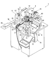
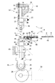
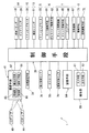
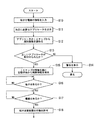
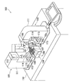
以下、本発明を実施するための最良の形態である端子圧着装置について、図1から図5に基づいて説明する。図1は本発明の一実施形態である端子圧着装置を示す斜視図であり、図2は端子圧着装置を図1とは反対側から示す斜視図であり、図3は端子圧着装置の端子圧着機構をアプリケータとともに示す正面図であり、図4は端子圧着装置の制御構成を示すブロック図であり、図5は端子圧着装置のICチップによる動作を説明するフローチャートである。 Hereinafter, a terminal crimping apparatus which is the best mode for carrying out the present invention will be described with reference to FIGS. 1 is a perspective view showing a terminal crimping apparatus according to an embodiment of the present invention, FIG. 2 is a perspective view showing the terminal crimping apparatus from the side opposite to FIG. 1, and FIG. 3 is a terminal crimping terminal of the terminal crimping apparatus. FIG. 4 is a front view showing the mechanism together with the applicator, FIG. 4 is a block diagram showing the control configuration of the terminal crimping apparatus, and FIG. 5 is a flowchart for explaining the operation of the terminal crimping apparatus by the IC chip.
本実施形態の端子圧着装置1は、図1および図2に示すように、電線癖取装置2と、電線Lの先端側に端子Tを圧着させるための第一圧着機構3と、電線Lの後端側に端子Tを圧着させるための第二圧着機構4と、電線Lを切断するとともに電線Lの端部の被覆材を除去する切断機構5と、電線Lの先端側を第一圧着機構3に送り込む電線送り機構6と、切断後の電線Lを保持し電線Lの後端側を第二圧着機構4に送り込むチャック機構7と、端子Tを圧着し終えた電線Lを蓄えた後に電線Lを外部へ排出する排出装置8とを備えている。本例の端子圧着装置1は、加工中の電線Lの向きを変えることなく、直線状に電線Lを送りながら加工することのできるものである。なお、図2は電線癖取装置2を省略して示している。
As shown in FIGS. 1 and 2, the
第一圧着機構3と第二圧着機構4とは基本的な構成が等しいため、以下、第一圧着機構3について説明し、第二圧着機構4についての詳細な説明は省略する。第一圧着機構3は、図1および図3に示すように、端子Tを圧着するアプリケータ9を取付けるフレーム部材10を備えている。このフレーム部材10の側面には、切欠き11が形成されており、その切欠き11内にアプリケータ9が取付けられている。詳しくは、切欠き11の上方には後述するアプリケータ9の上側ユニット12が、また、切欠き11の下方には、アプリケータ9の下側ユニット13が夫々取付けられており、第一圧着機構3には、アプリケータ9の上側ユニット12および下側ユニット13を別々に昇降させる第一昇降機構14および第二昇降機構15とが備えられている。
Since the first crimping mechanism 3 and the second crimping mechanism 4 have the same basic configuration, the first crimping mechanism 3 will be described below, and a detailed description of the second crimping mechanism 4 will be omitted. As shown in FIGS. 1 and 3, the first crimping mechanism 3 includes a
図3に示すように、第一昇降機構14は、上下方向に延び、下端部がフレーム部材10の切欠き11内部に露出するロッド16と、フレーム部材10に固定され、ロッド16を摺動可能に保持する保持部材17と、保持部材17の上部に配置されロッド16を昇降させる昇降シリンダ18と、昇降シリンダ18により降下したロッド16の上方の空間にロック部材19を挿入するロックシリンダ20と、ロッド16の下端部に固定され、アプリケータ9の上側ユニット12を連結する被連結部21と、保持部材17と被連結部21とを互いに接近する方向に付勢するバネなどからなる付勢手段22とから構成されている。
As shown in FIG. 3, the first elevating
また、第一昇降機構14の昇降シリンダ18は、ロッド16の上端部に固定され、ロッド16の軸直角方向に突出する連結片23を介してロッド16に取付けられており、この連結片23により、昇降シリンダ18の軸心とロッド16の軸心とは偏芯した位置に配置されている。
Further, the elevating
この第一昇降機構14は、昇降シリンダ18により、ロッド16を下降させると、ロッド16の上方に空間が形成され、その空間にロックシリンダ20により水平方向からロック部材19を挿入する。これにより、ロッド16の上昇を規制することが可能となる。なお、図示は省略するがロック部材19は、ロックシリンダ20側にバネなどからなる付勢手段により付勢されており、ロックシリンダ20の駆動力を解除することで、ロック部材19は、ロッド16上方の空間から排除され、ロックが解除される。また、保持部材17と被連結部21との間に設けられた付勢手段22により、昇降シリンダ18の駆動力とロック部材19のロックとが解除されると、ロッド16は上昇した状態となる。
When the
一方、第二昇降機構15は、上下方向に延び、上端部がフレーム部材12の切欠き13内部に露出するロッド24と、フレーム部材10に固定され、ロッド24を摺動可能に保持する保持部材25と、保持部材25の下方に位置するとともにロッド24の下端部に固定され、ローラ26を回転可能に支持するローラ支持部材27と、ローラ支持部材27の下方に配置されローラ支持部材27のローラ26と接触するカム面28を備えた回転カム29と、回転カム29を回転駆動するステッピングモータ30と、回転カム29のカム面28からローラ26が離れないように、ローラ支持部材27を介してローラ26を回転カム29の方向へバネなどにより付勢する付勢手段31と、ロッド24の先端部に固定されアプリケータ9の下側ユニット13を連結する被連結部32とから構成されている。
On the other hand, the second elevating
第二昇降機構15の回転カム29は、その回転中心とカム面28までの半径距離が、図中反時計回りの方向に進むに従って大きくなるように形成されており、およそ一周する手前辺りでその半径差を繋ぐような形状とされている。
The
また、この第二進退機構15には、ロッド24の所定位置に、その軸直角方向に突出する突起33と、ロッド24の昇降に伴って移動する突起33の位置を検知する位置検知手段34とがさらに備えられている。
The second advancing /
この第二昇降機構15は、ステッピングモータ30により、回転カム29を図中時計回りの方向に回転させることで、ロッド24を上昇させることができ、ロッド24とともに上昇する突起33の位置を位置検知手段34により検知し、その検知結果を基に、後述の制御手段39がステッピングモータ30の回転を制御しロッド24の位置、すなわち、下側ユニット13の上昇位置を制御する。これにより、ローラ28の寸法誤差などによるガタツキを微調整するとともに、端子Tの圧着圧力を適正なものとする。なお、ステッピングモータ30により回転カム29を上昇時とは逆方向に回転させることで、下側ユニット13を上昇位置から下降させることができる。
The second elevating
次に、アプリケータ9は、図3に示すように、上側ユニット12と、下側ユニット13とに互いに分離されており、個々に交換可能な状態で第一圧着機構3に取付けられている。上側ユニット12及び下側ユニット13には、押圧部材35及びアンビル36が取付けられており、上側ユニット12及び下側ユニット13を互いに接近させることで、押圧部材35とアンビル36との間に位置する端子Tを圧潰することができる。
Next, as shown in FIG. 3, the
上側ユニット12は、第一圧着機構3に着脱可能に取付けるための連結部37が設けられており、この連結部37が第一昇降機構14の被連結部21に連結されるようになっている。連結部37の下方には、上側ユニット本体38が設けられており、その下端に二枚の板材からなる押圧部材35が取付けられている。この押圧部材35の間には、図示しない払落し部材が上下方向に摺動可能に支持されており、下方へ移動させることで、押圧部材35に挟持された端子Tを下方へ払い落とすことができる。
The
この上側ユニット12の上側ユニット本体38には、ICチップ40が備えられており、このICチップ40には、上側ユニット12を特定するための識別情報が書込まれている。このICチップ40は、後述の通信手段41(図4参照)から送信された高周波などの電波を受信すると、その電波を電気に変換して蓄え、その電力が所定量に達すると、ICチップ40の記憶部に識別情報を書込んだり、識別情報を発信したりすることができるものである。
The
一方、下側ユニット13は、第二昇降機構15に設けられた被連結部32に対して着脱可能な連結部42と、連結部42の上方に固定されたアンビル36と、連結部42の上方に位置するとともに水平方向に延出された端子搬送機構43とを具備している。なお、アンビル33は、上側ユニット14の押圧部材32の下方に配置されている。また、上側ユニット12と同様に、下側ユニット13にも、ICチップ44が備えられており、このICチップ44には、下側ユニット13を特定するための識別情報が書込まれている。
On the other hand, the
端子搬送機構43は、板状のキャリア45によって一連に繋がれた端子Tを一つずつアンビル36上に順次供給するものであり、ベース部材46と、ベース部材46に形成されキャリア45を案内する溝状のガイド部47と、ガイド部47の開口部分を部分的に塞ぎキャリア45の逸脱を防止する逸脱防止機構48と、端子Tに係止爪49を係止させることでキャリア45によって繋がれた端子Tを搬送させる搬送機構50と、搬送機構50を水平方向に摺動させる搬送シリンダ51(図4参照)と、端子Tをアンビル36上に停止させるための制止機構52とを備えている。なお、図中符号53は、端子Tの圧潰動作の際、端子Tをキャリア45から切り離す切断部である。
The
この端子搬送機構43は、搬送シリンダ51により搬送機構50の係止爪49を、アンビル36の方向に移動させると、係止爪49が端子Tとキャリア45とを繋ぐ部分に係止して、端子Tをアンビル36上に搬送する。このとき、搬送機構50が制止機構52の回転部材に当接して回転部材が回転し、回転部材に形成された押圧部がキャリア45を下方からガイド部47の上部に押し付けられ、キャリア45の移動が制止し、端子Tがアンビル36上に停止するようになっている。
When the
次に、切断機構5は、第一圧着機構3と第二圧着機構4との間に配置され、電線Lの切断や、電線Lの端部の被覆材を除去するものであり、電線Lの被覆材を除去するために上下方向に配置された一対の切込刃54と、図示は省略するが、電線Lを切断するために上下方向に配置された一対の切断刃とを備えている。それら、切込刃54および切断刃は、夫々独立して開閉することができ、ステッピングモータ55を有した開閉手段56により、開閉駆動するようになっている。
Next, the
一方、電線送り機構6は、図1に示すように、電線取込みガイド57、電線Lの長さを測長するエンコーダ58、所定距離離間して配置される一対のローラ59、及びガイドパイプ60等から構成されている。なお、一対のローラ59は、互いに接近および離反するように移動可能とされ、また、ローラ59がローラ駆動手段61(図4参照)により回転駆動され、回転方向及び回転数を制御することにより、電線Lを任意の長さ送るとともに、エンコーダ58によるフィードバック制御を可能にしている。また、ガイドパイプ60は、図示しないガイドパイプ駆動手段62(図4参照)により、そのパイプの先端をアプリケータ9や切断機構5の近傍に位置させて、端子Tの圧着、切断や被覆材の除去の際に電線Lが振れたりするのを防止するものである。
On the other hand, as shown in FIG. 1, the
また、チャック機構7は、図2に示すように、第一,第二圧着機構3,4および切断機構5を挟んで、電線送り機構6とは反対側に配置されている。このチャック機構7は、上下方向に対向配置された一対の把持部63と、一対の把持部63を開閉するチャック開閉機構64と、把持部63とともにチャック開閉機構64を電線の送り方向に移動するチャック移動手段65(図4参照)と、電線Lを載置し電線Lの送りを補助するコンベア66とから構成されている。このチャック機構7の把持部63は、V字形状をしており、特に、下側の把持部63により、電線Lを受けるとともに、把持部63を閉動作することで、電線Lが把持部63の中心に移動し、電線Lの軸心を保つことができる。このチャック機構7は、切断機構5で切断された電線Lを把持するとともに、電線Lの後端部の加工の際に電線Lをその軸方向に移動させるものであり、その際に電線Lがスムーズに移動できるように、電線Lの移動に同調して電線Lを載置したコンベア66が作動するようになっている。
Further, as shown in FIG. 2, the chuck mechanism 7 is disposed on the opposite side of the
さらに、排出装置8は、チャック機構7の側方に配置され、チャック機構7から電線Lを受け取る受取機構67と、受取機構67を移動させて電線Lをチャック機構7から移動させる移動機構68と、移動機構68により移動した電線Lを受け取って収容する収容部69を備えた回転収容装置70とから構成されている。この排出装置8は、加工された電線Lを所定量収容した後に外部に排出するものである。なお、符号71は、受取機構67を移動させる移動機構68の駆動手段であり、符号72は、回転収容装置70における収容部69を回転させる回転駆動手段である。
Further, the
また、端子圧着装置1には、アプリケータ9に望むように端子ガイド機構73が配置されている。この端子ガイド機構73は、端子Tをガイドするガイドローラ74と、搬送される端子Tの振れを抑制する一対の振れ止板75と、端子Tの有無を検知する端子有無センサ76(図4参照)と、これらガイドローラ74、振れ止板75など支持するフレーム部材77とから構成されている。この端子ガイド機構73は、端子圧着装置1のテーブル78の下側に収容された図示しない端子リールに巻かれた端子Tを、アプリケータ9に安定して案内するとともに、端子Tの有無を検知するものである。
Further, the
さらに、端子圧着装置1には、図1に示すように、電線送り機構6の前方(電線Lの上流側)に、電線癖取装置2が配置されている。この電線癖取装置2は、所定間隔に配置された複数のローラと、電線Lの有無を検知する電線有無センサ79(図4参照)とを備えており、複数のローラ間に電線Lを通すことで、電線Lの曲げ癖を直し、電線Lを真直ぐにするとともに、電線Lの有無を検知することのできるものである。
Furthermore, as shown in FIG. 1, the
さらに、端子圧着装置1には、制御手段39を備えた操作部80(図1参照)が設けられており、この操作部80において、所定の情報を入力することで、制御手段39により端子圧着装置1が制御される。操作部80は、電線Lを加工するための種々の情報を入力する入力手段81と、入力内容などを表示する出力手段82とが備えられており、それらは制御手段39に夫々接続されている(図4参照)。制御手段39は、中央情報処理装置(CPU)と、それを補佐するRAMやROMなどの補佐記憶装置とからなっている。なお、図1中符号83は、第一,第二圧着機構3,4を個別に制御する副操作部である。
Further, the
図4に示すように、制御手段39には、アプリケータ9の上側ユニット12および下側ユニット13に備えられたICチップ40,44に識別情報を書込んだり、読込んだりするための通信手段41と、端子圧着装置1の制御情報や管理情報などを記憶する記憶手段84とがさらに接続されている。この記憶手段84は、RAM、ROMなどのメモリ、ハードディスク、コンパクトディスク、光磁気ディスク、デジタルビデオディスクなどの読取専用あるいは書込み可能な記憶媒体を駆動する駆動手段、それらのメモリや記憶媒体に書込み及び読出しをおこなう記録手段、などから構成されている。
As shown in FIG. 4, the control means 39 is a communication means for writing or reading the identification information on the IC chips 40 and 44 provided in the
この記憶手段84には、予めICチップの識別情報と関連付けて、端子の種類、押圧部材の送り量、アンビルの送り量、圧潰圧力、電線の種類、電線の被覆材の除去長さ、電線と端子との位置関係、電線の切断位置、端子の搬送タイミング、アプリケータの使用回数、保管場所、などの制御情報や管理情報が記憶されている。 In this storage means 84, the terminal type, the pressing member feed amount, the anvil feed amount, the crushing pressure, the wire type, the wire covering material removal length, the wire Control information and management information such as the positional relationship with the terminal, the cutting position of the electric wire, the conveyance timing of the terminal, the number of times the applicator is used, and the storage location are stored.
また、通信手段41は、ICチップに電源を供給したり、ICチップに情報を書込んだりするための電波を発信する発信部85と、ICチップから送信された情報を受信する受信部86と、発信部85を制御してICチップに情報を書込むためにの書込み手段87と、発信部85と受信部86とを制御してICチップの情報を読取る読取り手段88とから構成されている。
In addition, the
次に、本実施形態の端子圧着装置1の動作の一例を図面に基づいて説明する。まず、図5に示すように、操作部80の入力手段81から、所望とする製品、つまり、端子付電線の情報を入力する(ステップS10)。すると、ステップS11では、制御手段39が入力された情報を基に記憶手段84から対応するアプリケータ9の情報を読出し、第一,第二圧着機構3,4に取付けるアプリケータ9の情報を操作部80の出力手段82に表示出力する。そして、作業者が、その表示内容を基に、所望のアプリケータ9を第一,第二圧着機構3,9に夫々取付けると、ステップS12において、読取り手段88により発信部85から電波が発信され、その電波によりアプリケータ9に備えらされたICチップ40,44から識別情報が発信され、受信部86で受信して読取り手段88で読取られる。
Next, an example of operation | movement of the
その後、ステップS13では、読取ったICチップ40,44の識別情報を基に、記憶手段84に記憶された情報と照合し、取付けたアプリケータ9が違っていれば、ステップS14へ進み、操作部80の出力手段82に警告などその旨を出力し、正しいアプリケータ9の取付けを促す。一方、取付けたアプリケータ9が間違いなければ、詳しくは、アプリケータ9には、上側ユニット12と下側ユニット13とに夫々ICチップ40,44が内蔵されており、両方ともが正しい場合には、次のステップS15へと進む。
Thereafter, in step S13, based on the read identification information of the IC chips 40 and 44, the information stored in the storage means 84 is collated. If the attached
ステップS15では、ICチップ40,44の識別情報を基に、制御手段は39、記憶手段84から、対応する制御情報を抽出する。ここでは、上側ユニット12の下降量、下側ユニット13の上昇位置、端子Tの圧潰圧力、電線Lの太さ、電線L端部の被覆材の除去長さ、などが制御情報として抽出される。その後、アプリケータ9における下側ユニット13の端子搬送機構43にキャリア45に繋がれた一連の端子Tが挿入されると、端子ガイド機構73の端子有無センサ76が端子Tを検出する(ステップS16)。また、電線送り機構6に電線癖取装置2を介して電線Lがセットされると、電線癖取装置2の電線有無センサ79が電線Lを検出(ステップS17)して、電線Lの加工準備が完了し、端子圧着装置1の作動が許可され(ステップS18)、待機状態となる。その後、操作部80から加工する電線Lの数量、長さ、などが入力され、端子圧着装置1の作動開始が指示されると、電線Lの加工を開始する。
In step S15, based on the identification information of the IC chips 40 and 44, the control means extracts the corresponding control information from 39 and the storage means 84. Here, the lowering amount of the
まず、電線Lは、電線送り機構6のローラ駆動手段61によりローラ59が回転することで、電線Lの先端が切断機構5へと送られ、電線Lの先端が切込刃54から所定量、すなわち、ICチップ40,44の識別情報を基に記憶手段84から抽出された、電線Lの被覆材の除去長さ分突出した位置で停止する。このとき、ガイドパイプ駆動手段62によりガイドパイプ60も、切断機構5の近傍まで前進する。そして、ステッピングモータ55の駆動により一対の切込刃54が電線Lの芯線まで切込んだ後に、電線Lから離れない程度に若干後退する。これにより、芯線に傷が付くのを防ぐとともに、小さい力で引抜くことができる。その後、電線送り機構6のローラ59が逆回転し、電線L先端の被覆材が除去されるとともに、電線Lの先端は、第一圧着機構3におけるアプリケータ9の押圧部材35とアンビル36との間まで後退する。また、ガイドパイプ60も合せて後退する。
First, the
次に、第一圧着機構3における第一昇降機構14の昇降シリンダ18により上側ユニット12が下降し、次いでロックシリンダ20が作動して、ロック部材19により上側ユニット12の上下動がロックされる。その後、第二昇降機構15のステッピングモータ30が回転し回転カム29の作用により、下側ユニット13が所定量、すなわち、ICチップ40,44の識別情報を基に記憶手段84から抽出された、第二昇降機構15のロッド24に形成された突起33の上昇位置、すなわち、アンビル36の上昇位置、まで上昇する。そして、制御手段39は、回転カム29の回転により突起33が所定の上昇位置に到達したことを位置検知手段34により検知すると、ステッピングモータ30の回転を停止させる。これにより、下側ユニット13は所定の上昇位置に停止し、押圧部材35とアンビル36とで端子Tが圧潰され電線Lの先端部に端子Tが圧着される。
Next, the
電線Lの先端部に端子Tが圧着されると、上側ユニット12および下側ユニット13が夫々上昇および下降し、電線Lを開放して互いに遠ざかる。続いて、電線送り機構6のローラ59が回転し電線Lが所定長さ送られる。なお、電線Lの長さは、エンコーダ58により測長されており、所定長さに達するとローラ59の回転が停止する。すると、チャック機構7のチャック開閉機構64が作動し電線Lの後端を一対の把持部63により把持し、切断機構5の切断刃が閉駆動して、電線Lが所定長さに切断される。なお、電線Lの先端側は、チャック機構7のコンベア66に載置される。
When the terminal T is crimped to the tip of the electric wire L, the
電線Lが切断されると、チャック開閉機構64は、電線Lを把持したまま、チャック移動手段65により、電線Lの後端が切断機構5の切込刃54から所定量となるように電線Lの送り方向と逆方向に移動する。そして、切込刃54により切込まれた後、チャック移動手段65によりチャック開閉機構64が電線Lの送り方向に移動すると、電線Lの後端の被覆材が除去されるとともに、電線Lの後端は、第二圧着機構4におけるアプリケータ9の押圧部材35とアンビル36との間まで移動する。
When the electric wire L is cut, the chuck opening /
第二圧着機構4でも、第一圧着機構3と同様の動作がおこなわれ、電線Lの後端部に端子Tが圧着される。両端部に端子Tが圧着された電線Lは、チャック機構7から排出機構8の受取機構67へと受け渡され、電線Lを受け取った受取機構67は、駆動手段71により回転収容装置70の上方に移動すると、電線Lを放し、電線Lは、回転収容装置70の収容部69に収容される。なお、アプリケータ9では、端子Tが圧潰されると、下側ユニット13における搬送機構50の搬送シリンダ51が駆動され、次の端子Tがアンビル36上に搬送される。
In the second crimping mechanism 4, the same operation as that of the first crimping mechanism 3 is performed, and the terminal T is crimped to the rear end portion of the electric wire L. The electric wire L with the terminals T crimped to both ends is transferred from the chuck mechanism 7 to the
上記の一連の動作により両端部に端子Tを圧着した電線Lが形成され、この一連の動作が所定回数繰り返される。なお、回転収容装置70は、収容部69に所定数量の電線Lが収納されると回転駆動手段72により回転し、電線Lすなわち端子付電線を端子圧着装置1の外部に排出する。
The electric wire L which crimped | bonded the terminal T to the both ends is formed by said series of operation | movement, and this series of operation | movement is repeated predetermined times. The rotation
このように、本実施形態の端子圧着装置1によると、電線Lの送り方向に対して、上流側から順に、電線送り機構6、第一圧着機構3、切断機構5、第二圧着機構4、チャック機構7が配置されており、電線Lを直線状に送って、電線Lに種々の加工を行うようにしており、加工の際に電線Lに無駄な動きを可及的に少なくすることができ、端子付電線の生産効率を飛躍的に高めることができる。
Thus, according to the
また、アプリケータ9の上側ユニット12と下側ユニット13に備えたICチップ40,44の識別情報を基に、記憶手段84から予め関連付けて記憶された制御情報を抽出して端子圧着装置1を制御しており、端子圧着機構にアプリケータ9を取付けることで、そのアプリケータ9に対応した制御情報を抽出して、自動的に押圧部材やアンビルの位置調整を行ったり、電線送り機構6、切断機構5やチャック機構7などの動作設定を自動的に行うことも可能となる。そのため、アプリケータ9を交換しても、作業者が押圧部材やアンビルなどの位置調整を行う必要がなく、作業者による調整のバラツキを防止して端子付電線の品質を一定に維持するとともに、他の機構の動作設定などを入力する必要がないので、交換に係る時間を短縮して、生産性を高め、多品種少量生産に対応することができる。
Further, based on the identification information of the IC chips 40 and 44 provided in the
さらに、電線送り機構6では、電線Lを直線状に送る機能があればよく、従来のように電線Lの向きを変える機能を必要としないので、電線送り機構6の構成を簡略化することが可能となる。また、電線Lの向きを変える必要がないので、電線Lの向きを変えることで発生する慣性も作用することがなく、電線Lの位置決め精度を高めることができるとともに、電線Lの送り速度を向上させることができ、端子圧着装置1の効率を高めることができる。
Furthermore, the
また、アプリケータ9として、押圧部材35を備えた上側ユニット12と、アンビル36を備えた下側ユニット13とを分離した形態としているので、押圧部材35とアンビル36とを夫々別々に移動させることが可能となり、電線Lの端部に端子Tを圧着した後に、押圧部材35とアンビル36とを夫々端子Tから遠ざけることが可能となる。これにより、電線Lを真直ぐ送る際に押圧部材35やアンビル36が電線Lに接触するのを回避するとともに、電線Lに曲がり癖が付くことを防止することが可能となり、このアプリケータ9を用いることで、電線Lを直線状に送って、電線Lに種々の加工を行う端子圧着装置1を容易に実現することができ、端子付電線の生産効率を飛躍的に高めることができる。
Since the
さらに、第一圧着機構3と第二圧着機構4との間に切断機構5を配置したことにより、電線Lの先端部の被覆材の除去と、電線Lの切断と、電線Lの後端部の被覆材の除去とを一つの切断機構で行うとともに、被覆材を除去する位置と端子Tを圧着する位置とを可及的に近づけることができるので、装置構成を簡略化することが可能となるとともに、装置全体を小型化することができる。
Furthermore, by disposing the
以上、本発明について好適な実施形態を挙げて説明したが、本発明はこれらの実施形態に限定されるものではなく、以下に示すように、本発明の要旨を逸脱しない範囲において、種々の改良及び設計の変更が可能である。 The present invention has been described with reference to preferred embodiments. However, the present invention is not limited to these embodiments, and various modifications can be made without departing from the spirit of the present invention as described below. And design changes are possible.
すなわち、本実施形態の端子圧着装置1は、アプリケータ9を上側ユニット12と下側ユニット13とが分離した形態のものを示したが、これに限定するものではなく、押圧部材とアプリケータとを夫々移動可能であればよく、上側ユニットと下側ユニットとが一体的に形成された形態のものであってもよい。これによれば、上側ユニットと下側ユニットとが一体的になっているので、端子圧着機構へのアプリケータの取付けが一度にすむので、取付けに係る手間を簡略化することができる。
That is, although the
1 端子圧着装置
3 第一圧着機構
4 第二圧着機構
5 切断機構
6 電線送り機構
7 チャック機構
9 アプリケータ
12 上側ユニット
13 下側ユニット
35 押圧部材
36 アンビル
39 制御手段
40 ICチップ
44 ICチップ
84 記憶手段
87 書込み手段
88 読取り手段
1 terminal crimping device 3 first crimping mechanism 4 second crimping
Claims (1)
該電線送り機構により送られた電線を把持するとともに電線をその送り方向に送ることのできるチャック機構と、
該チャック機構および前記電線送り機構により送られる電線の切断および端部の被覆材の除去をするための切断機構と、
前記電線送り機構により送られた電線の先端部に端子を圧着する第一圧着機構と、
前記チャック機構により送られた電線の後端部に端子を圧着する第二圧着機構と、
前記第一圧着機構および前記第二圧着機構に夫々脱着可能に取付けられ、押圧部材を備えた上側ユニットと、押圧部材の下方に配置されるアンビルを備えた下側ユニットとからなるとともに、前記第一圧着機構および前記第二圧着機構により上側ユニットと下側ユニットとを互いに接近および離反するように夫々独立して移動させて、押圧部材とアンビルとで端子を圧潰するアプリケータと、
該アプリケータの上側ユニットと下側ユニットとに夫々備えられるICチップと、
該ICチップに前記アプリケータの上側ユニットと下側ユニットとを識別するための識別情報を書込む書込み手段と、
該書込み手段により書込まれた前記識別情報を前記ICチップから読取る読取り手段と、
該読取り手段により読取った前記ICチップの前記識別情報を用いて、予め記憶手段に前記識別情報と関連付けて記憶された制御情報を前記記憶手段から抽出し、抽出した前記制御情報を基に、少なくとも、前記電線送り機構、前記チャック機構、前記切断機構、前記第一圧着機構、前記第二圧着機構、を制御する制御手段とを具備し、
前記電線送り機構による電線の送り方向に対して上流から下流に向かって、前記電線送り機構、第一圧着機構、切断機構、第二圧着機構、チャック機構の順に配置して、電線の向きを変えることなく、電線を直線状に送りながら、電線を加工することを特徴とする端子圧着装置。 An electric wire feeding mechanism for feeding electric wires in a straight line;
A chuck mechanism capable of gripping the electric wire sent by the electric wire feeding mechanism and sending the electric wire in the feeding direction;
A cutting mechanism for cutting the electric wire fed by the chuck mechanism and the electric wire feeding mechanism and removing the covering material at the end;
A first crimping mechanism for crimping a terminal to the tip of the wire sent by the wire feeding mechanism;
A second crimping mechanism for crimping a terminal to the rear end of the electric wire sent by the chuck mechanism;
Each of the first pressure-bonding mechanism and the second pressure-bonding mechanism is detachably attached and includes an upper unit having a pressing member and a lower unit having an anvil disposed below the pressing member. An applicator for independently moving the upper unit and the lower unit so as to approach and separate from each other by one crimping mechanism and the second crimping mechanism, and crushing the terminal with the pressing member and the anvil;
IC chips respectively provided in the upper unit and the lower unit of the applicator;
Writing means for writing identification information for identifying the upper unit and the lower unit of the applicator on the IC chip;
Reading means for reading the identification information written by the writing means from the IC chip;
Using the identification information of the IC chip read by the reading means, control information stored in advance in the storage means in association with the identification information is extracted from the storage means, and based on the extracted control information, at least A control means for controlling the wire feeding mechanism, the chuck mechanism, the cutting mechanism, the first crimping mechanism, and the second crimping mechanism,
The wire feed mechanism, the first crimping mechanism, the cutting mechanism, the second crimping mechanism, and the chuck mechanism are arranged in this order from upstream to downstream with respect to the wire feeding direction by the wire feeding mechanism to change the direction of the wires. A terminal crimping apparatus characterized by processing an electric wire while feeding the electric wire in a straight line.
Priority Applications (1)
| Application Number | Priority Date | Filing Date | Title |
|---|---|---|---|
| JP2003402781A JP2005166399A (en) | 2003-12-02 | 2003-12-02 | Terminal crimping device |
Applications Claiming Priority (1)
| Application Number | Priority Date | Filing Date | Title |
|---|---|---|---|
| JP2003402781A JP2005166399A (en) | 2003-12-02 | 2003-12-02 | Terminal crimping device |
Publications (1)
| Publication Number | Publication Date |
|---|---|
| JP2005166399A true JP2005166399A (en) | 2005-06-23 |
Family
ID=34726260
Family Applications (1)
| Application Number | Title | Priority Date | Filing Date |
|---|---|---|---|
| JP2003402781A Pending JP2005166399A (en) | 2003-12-02 | 2003-12-02 | Terminal crimping device |
Country Status (1)
| Country | Link |
|---|---|
| JP (1) | JP2005166399A (en) |
Cited By (18)
| Publication number | Priority date | Publication date | Assignee | Title |
|---|---|---|---|---|
| JP2010262877A (en) * | 2009-05-11 | 2010-11-18 | Japan Automat Mach Co Ltd | Terminal crimped wire manufacturing apparatus and terminal crimped wire manufacturing method |
| KR200452955Y1 (en) | 2009-09-04 | 2011-03-31 | 이원종 | Automatic terminal device of terminal joint of connector terminal |
| WO2011145200A1 (en) * | 2010-05-20 | 2011-11-24 | 日本オートマチックマシン株式会社 | Stripping/crimping device for electrical wire |
| WO2011158527A1 (en) * | 2010-06-16 | 2011-12-22 | 日本オートマチックマシン株式会社 | Multiple crimped wire manufacturing device, multiple crimped wire manufacturing method, multiple wire feeding device, terminal crimping method, and terminal crimping device |
| CN101477828B (en) * | 2008-11-18 | 2012-05-23 | 台达电子电源(东莞)有限公司 | Automatic IC burning machine |
| CN103187678A (en) * | 2013-03-14 | 2013-07-03 | 北京工业大学 | Feeding box device for double-end crimping |
| CN105977756A (en) * | 2016-06-16 | 2016-09-28 | 蒋清校 | Linear multi-pulley electric wire conveying unidirectional fuse tube conveying and welding production line |
| CN108233148A (en) * | 2018-01-03 | 2018-06-29 | 厦门海普锐科技股份有限公司 | A variety of terminal feeding devices, method and composite press connection device |
| KR101991128B1 (en) * | 2018-12-22 | 2019-06-25 | 김동식 | Apparatus of combining a terminal to a cable |
| JP6633822B1 (en) * | 2019-08-05 | 2020-01-22 | 新明和工業株式会社 | Electric wire straightening device, electric wire processing device provided with the same, electric wire straightening method and manufacturing method |
| CN112563081A (en) * | 2020-12-02 | 2021-03-26 | 东莞市佳豪精工科技有限公司 | Full-automatic fuse riveting machine |
| CN113193454A (en) * | 2021-04-30 | 2021-07-30 | 苏州瀚川智能科技股份有限公司 | Terminal integrated forming device |
| CN113839285A (en) * | 2020-06-24 | 2021-12-24 | 施洛伊尼格股份公司 | Cable processing apparatus, computer-implemented method, computer program, and computer-readable storage medium for processing cables |
| WO2022045462A1 (en) * | 2020-08-28 | 2022-03-03 | 황원주 | Wire terminal processing device |
| WO2023127448A1 (en) * | 2021-12-27 | 2023-07-06 | Yazaki Corporation | Electric wire processing apparatus and electric wire processing method |
| KR102728300B1 (en) * | 2023-06-27 | 2024-11-08 | (주)세림전자 | apparatus for assembling connector |
| KR102839404B1 (en) * | 2024-03-13 | 2025-07-28 | (주)세림전자 | apparatus for assembling connector |
| KR102890793B1 (en) * | 2024-09-02 | 2025-11-25 | 주식회사 에이치피케이 | Wire pickup unit and FPCB sensor-wire soldering device including the same |
Citations (5)
| Publication number | Priority date | Publication date | Assignee | Title |
|---|---|---|---|---|
| JPH07220770A (en) * | 1994-01-31 | 1995-08-18 | Sumitomo Wiring Syst Ltd | Structure, method and device for crimping terminal |
| JPH08241779A (en) * | 1995-03-07 | 1996-09-17 | Yazaki Corp | Automatic manufacturing equipment for electric wires with terminals |
| JPH11273824A (en) * | 1998-03-24 | 1999-10-08 | Kodera Denshi Seisakusho:Kk | Crimping machine and terminal sequential crimping device using the same |
| JP2000123946A (en) * | 1998-10-16 | 2000-04-28 | Sumitomo Wiring Syst Ltd | Terminal crimping machine |
| JP2000208228A (en) * | 1999-01-11 | 2000-07-28 | Kodera Denshi Seisakusho:Kk | Terminal crimping device |
-
2003
- 2003-12-02 JP JP2003402781A patent/JP2005166399A/en active Pending
Patent Citations (5)
| Publication number | Priority date | Publication date | Assignee | Title |
|---|---|---|---|---|
| JPH07220770A (en) * | 1994-01-31 | 1995-08-18 | Sumitomo Wiring Syst Ltd | Structure, method and device for crimping terminal |
| JPH08241779A (en) * | 1995-03-07 | 1996-09-17 | Yazaki Corp | Automatic manufacturing equipment for electric wires with terminals |
| JPH11273824A (en) * | 1998-03-24 | 1999-10-08 | Kodera Denshi Seisakusho:Kk | Crimping machine and terminal sequential crimping device using the same |
| JP2000123946A (en) * | 1998-10-16 | 2000-04-28 | Sumitomo Wiring Syst Ltd | Terminal crimping machine |
| JP2000208228A (en) * | 1999-01-11 | 2000-07-28 | Kodera Denshi Seisakusho:Kk | Terminal crimping device |
Cited By (29)
| Publication number | Priority date | Publication date | Assignee | Title |
|---|---|---|---|---|
| CN101477828B (en) * | 2008-11-18 | 2012-05-23 | 台达电子电源(东莞)有限公司 | Automatic IC burning machine |
| JP2010262877A (en) * | 2009-05-11 | 2010-11-18 | Japan Automat Mach Co Ltd | Terminal crimped wire manufacturing apparatus and terminal crimped wire manufacturing method |
| KR200452955Y1 (en) | 2009-09-04 | 2011-03-31 | 이원종 | Automatic terminal device of terminal joint of connector terminal |
| WO2011145200A1 (en) * | 2010-05-20 | 2011-11-24 | 日本オートマチックマシン株式会社 | Stripping/crimping device for electrical wire |
| CN102511114A (en) * | 2010-05-20 | 2012-06-20 | 日本自动机械株式会社 | Stripping/crimping device for electrical wire |
| JP5095859B2 (en) * | 2010-05-20 | 2012-12-12 | 日本オートマチックマシン株式会社 | Electric wire strip crimper |
| WO2011158527A1 (en) * | 2010-06-16 | 2011-12-22 | 日本オートマチックマシン株式会社 | Multiple crimped wire manufacturing device, multiple crimped wire manufacturing method, multiple wire feeding device, terminal crimping method, and terminal crimping device |
| JP5060657B2 (en) * | 2010-06-16 | 2012-10-31 | 日本オートマチックマシン株式会社 | Multi-wire crimping wire manufacturing device, multi-two wire crimping wire manufacturing method, multi-wire wire feeder, terminal crimping method, and terminal crimping device |
| CN103187678A (en) * | 2013-03-14 | 2013-07-03 | 北京工业大学 | Feeding box device for double-end crimping |
| CN105977756A (en) * | 2016-06-16 | 2016-09-28 | 蒋清校 | Linear multi-pulley electric wire conveying unidirectional fuse tube conveying and welding production line |
| CN108233148A (en) * | 2018-01-03 | 2018-06-29 | 厦门海普锐科技股份有限公司 | A variety of terminal feeding devices, method and composite press connection device |
| CN108233148B (en) * | 2018-01-03 | 2024-03-22 | 厦门海普锐科技股份有限公司 | Multiple terminal supply device, multiple terminal supply method and multiple crimping device |
| KR101991128B1 (en) * | 2018-12-22 | 2019-06-25 | 김동식 | Apparatus of combining a terminal to a cable |
| JP6633822B1 (en) * | 2019-08-05 | 2020-01-22 | 新明和工業株式会社 | Electric wire straightening device, electric wire processing device provided with the same, electric wire straightening method and manufacturing method |
| WO2021024363A1 (en) * | 2019-08-05 | 2021-02-11 | 新明和工業株式会社 | Electric wire straightening device, electric wire processing device equipped therewith, method for straightening electric wire, and manufacturing method therefor |
| JP2022008204A (en) * | 2020-06-24 | 2022-01-13 | シュロニガー アーゲー | Cable mechanical processing device for mechanically processing cable, computer-implemented method, computer program product, and computer readable storage medium |
| CN113839285A (en) * | 2020-06-24 | 2021-12-24 | 施洛伊尼格股份公司 | Cable processing apparatus, computer-implemented method, computer program, and computer-readable storage medium for processing cables |
| KR102450404B1 (en) | 2020-08-28 | 2022-09-30 | 황원주 | Wire end processing device |
| WO2022045462A1 (en) * | 2020-08-28 | 2022-03-03 | 황원주 | Wire terminal processing device |
| KR20220028488A (en) * | 2020-08-28 | 2022-03-08 | 황원주 | Apparatus for processing end of wires |
| CN112563081B (en) * | 2020-12-02 | 2022-07-05 | 东莞市佳豪精工科技有限公司 | Full-automatic fuse riveting machine |
| CN112563081A (en) * | 2020-12-02 | 2021-03-26 | 东莞市佳豪精工科技有限公司 | Full-automatic fuse riveting machine |
| CN113193454A (en) * | 2021-04-30 | 2021-07-30 | 苏州瀚川智能科技股份有限公司 | Terminal integrated forming device |
| WO2023127448A1 (en) * | 2021-12-27 | 2023-07-06 | Yazaki Corporation | Electric wire processing apparatus and electric wire processing method |
| JP2023096899A (en) * | 2021-12-27 | 2023-07-07 | 矢崎総業株式会社 | Wire processing device and wire processing method |
| JP7490322B2 (en) | 2021-12-27 | 2024-05-27 | 矢崎総業株式会社 | Wire processing device and wire processing method |
| KR102728300B1 (en) * | 2023-06-27 | 2024-11-08 | (주)세림전자 | apparatus for assembling connector |
| KR102839404B1 (en) * | 2024-03-13 | 2025-07-28 | (주)세림전자 | apparatus for assembling connector |
| KR102890793B1 (en) * | 2024-09-02 | 2025-11-25 | 주식회사 에이치피케이 | Wire pickup unit and FPCB sensor-wire soldering device including the same |
Similar Documents
| Publication | Publication Date | Title |
|---|---|---|
| JP2005166399A (en) | Terminal crimping device | |
| EP2211600A2 (en) | Component feeder | |
| EP2938177B1 (en) | Automatic tape processing apparatus and automatic tape setting apparatus | |
| WO2011158390A1 (en) | Two crimped wire manufacturing device, two crimped wire manufacturing method, and two wire feeding device | |
| US10059014B2 (en) | Device for carrying out cutting operations of unbound formatting edges of a printed product | |
| JP3982480B2 (en) | Multi-crimping device and terminal supply module | |
| CN101213710A (en) | Terminal Feeder for Termination Machines | |
| JP6101546B2 (en) | Cutting device | |
| EP1967382A2 (en) | Bookbinding apparatus and image forming system | |
| US20250255384A1 (en) | Button Product Manufacturing Device, Button Product Manufacturing Method, and Non-Transitory Computer Readable Storage Medium | |
| CN100577542C (en) | Transporting device and transporting method for ultra-long film | |
| JP2006318915A (en) | Enveloper and device for forming battery plate group | |
| JP3186531B2 (en) | Terminal crimping wire manufacturing equipment | |
| JP2005151778A (en) | Terminal-crimping system | |
| US4854033A (en) | Inserting insulating material into electric motor stators | |
| CN105541096B (en) | Substrate processing device | |
| JP4074849B2 (en) | Terminal crimping device | |
| JP4101154B2 (en) | Terminal crimping applicator | |
| CN210986886U (en) | Double-pin electronic component welding and braiding all-in-one machine | |
| JP3261889B2 (en) | Terminal processing / press-fitting device | |
| JP4263155B2 (en) | Terminal pressing member and terminal crimping device | |
| CN212766950U (en) | Braid material supplier | |
| JP2006164804A (en) | Terminal transport apparatus | |
| JP2005158485A (en) | Terminal crimping device | |
| TWI262626B (en) | Apparatus for crimping a terminal |
Legal Events
| Date | Code | Title | Description |
|---|---|---|---|
| A621 | Written request for application examination |
Free format text: JAPANESE INTERMEDIATE CODE: A621 Effective date: 20050901 |
|
| A977 | Report on retrieval |
Free format text: JAPANESE INTERMEDIATE CODE: A971007 Effective date: 20071009 |
|
| A131 | Notification of reasons for refusal |
Free format text: JAPANESE INTERMEDIATE CODE: A131 Effective date: 20071023 |
|
| A521 | Written amendment |
Free format text: JAPANESE INTERMEDIATE CODE: A523 Effective date: 20071122 |
|
| A02 | Decision of refusal |
Free format text: JAPANESE INTERMEDIATE CODE: A02 Effective date: 20080122 |