JP2005166327A - air conditioner - Google Patents
air conditioner Download PDFInfo
- Publication number
- JP2005166327A JP2005166327A JP2003401142A JP2003401142A JP2005166327A JP 2005166327 A JP2005166327 A JP 2005166327A JP 2003401142 A JP2003401142 A JP 2003401142A JP 2003401142 A JP2003401142 A JP 2003401142A JP 2005166327 A JP2005166327 A JP 2005166327A
- Authority
- JP
- Japan
- Prior art keywords
- value
- heater
- control output
- current
- output
- Prior art date
- Legal status (The legal status is an assumption and is not a legal conclusion. Google has not performed a legal analysis and makes no representation as to the accuracy of the status listed.)
- Pending
Links
Images

Landscapes
- Control Of Resistance Heating (AREA)
- Control Of Temperature (AREA)
Abstract
【課題】 アナログ出力タイプの温度調節器において、ヒータの断線検知を可能にする。
【解決手段】
温度調節器2から出力される制御出力としての電流出力に応じて、電力調整器5では、交流電源3の位相を制御してヒータ4の通電量を制御する温度制御システムにおいて、温度調節器2は、電流センサ6で検出されるヒータ4の電流値を、制御出力値100%に対応する電流値に変換し、ヒータ断線の有無を判定するための設定値と比較し、設定値を下回ったときには、断線と判定して警報動作などを行なう。
【選択図】 図1PROBLEM TO BE SOLVED: To detect disconnection of a heater in an analog output type temperature controller.
[Solution]
In response to the current output as the control output output from the temperature regulator 2, the power regulator 5 controls the phase of the AC power supply 3 to control the energization amount of the heater 4. Converted the current value of the heater 4 detected by the current sensor 6 into a current value corresponding to the control output value of 100%, and compared with a set value for determining the presence or absence of heater disconnection, the value was below the set value. In some cases, it is determined that the wire is disconnected, and an alarm operation is performed.
[Selection] Figure 1
Description
本発明は、温度調節器に関し、更に詳しくは、連続的な電流出力のようなアナログの制御出力を、SSRや電力調整器などの電力操作器に出力するアナログ出力タイプの温度調節器に関する。 The present invention relates to a temperature controller, and more particularly, to an analog output type temperature controller that outputs an analog control output such as a continuous current output to a power controller such as an SSR or a power regulator.
近年の温度制御では、品質向上のために高精度化や高速化が望まれている。そのため、電力調整器を使用して半サイクル毎に出力量(電力量)を変化させる位相制御が増えている(例えば、特許文献1参照)。 In recent temperature control, high precision and high speed are desired for quality improvement. For this reason, there is an increase in phase control that changes the output amount (power amount) every half cycle using a power regulator (see, for example, Patent Document 1).
かかる温度制御では、アナログ出力タイプの温度調節器から制御出力として、例えば、4〜20mAの電流出力が電力調整器に与えられ、電力調整器では、この電流出力に応じて、ヒータに印加される交流電力の位相角(点弧角)を半サイクル毎に制御してヒータの通電量を制御している。
一般に、制御対象を加熱するヒータは、複数本、例えば、3本のヒータが並列に接続されて用いられており、いずれかのヒータが断線したときには、直ちにそれを検知して素早くヒータを交換するなどの適宜の措置をとる必要がある。 In general, a plurality of heaters, for example, three heaters, are connected in parallel and used for heating a controlled object. When one of the heaters is disconnected, it is immediately detected and the heater is quickly replaced. It is necessary to take appropriate measures such as.
このため、オンオフパルスを制御出力としてリレー等に出力し、リレーを介してヒータの通電量を制御するデジタル出力タイプの温度調節器においては、オンオフパルスがオンしている期間、すなわち、制御出力値の100%に相当する期間におけるヒータの通電電流を電流センサで検出して設定値と比較することによって、ヒータの断線を検知するようにしている。 For this reason, in a digital output type temperature controller that outputs an on / off pulse as a control output to a relay or the like and controls the energization amount of the heater via the relay, a period during which the on / off pulse is on, that is, a control output value The heater disconnection is detected by detecting the energization current of the heater in a period corresponding to 100% of the current with a current sensor and comparing it with a set value.
しかしながら、アナログ出力タイプの温度調節器では、アナログの制御出力値に応じて、電力調整器でヒータに印加される電力の位相が、半サイクル毎に制御されるために、デジタル出力タイプの温度調節器のようにオン期間が長く継続せず、このため、ヒータの通電電流を検出してヒータの断線を検出するのが困難であった。 However, in the analog output type temperature controller, the phase of the power applied to the heater by the power regulator is controlled every half cycle according to the analog control output value. The on-period does not continue for a long time as in the case of a heater, and for this reason, it is difficult to detect a heater breakage by detecting the energization current of the heater.
本発明は、このような実情に鑑みてなされたものであって、ヒータの断線を検知することが可能なアナログ出力タイプの温度調節器を提供することを目的とする。 The present invention has been made in view of such circumstances, and an object thereof is to provide an analog output type temperature controller capable of detecting disconnection of a heater.
本発明では、上記目的を達成するために、次のように構成している。 In order to achieve the above object, the present invention is configured as follows.
すなわち、本発明は、アナログの制御出力を電力操作器に出力して制御対象を加熱するヒータの通電を制御する温度調節器において、電流センサで検出される前記ヒータの電流値および前記制御出力値に基づいて、前記ヒータの断線を検知する断線検知手段を備えている。 That is, according to the present invention, in the temperature controller that controls the energization of the heater that heats the controlled object by outputting an analog control output to the power controller, the heater current value and the control output value detected by the current sensor And a disconnection detecting means for detecting disconnection of the heater.
ここで、アナログの制御出力とは、連続的な制御出力(操作信号)をいい、例えば、電流出力をいう。 Here, the analog control output refers to a continuous control output (operation signal), for example, a current output.
本発明によると、電流センサで検出されるヒータの電流値と、アナログの制御出力値とに基づいて、ヒータの断線を検知するので、アナログ出力タイプの温度調節器において、ヒータの断線検知が可能となる。 According to the present invention, since the heater disconnection is detected based on the heater current value detected by the current sensor and the analog control output value, the disconnection of the heater can be detected in the analog output type temperature controller. It becomes.
本発明の一実施態様においては、前記ヒータは、並列接続された複数のヒータからなるものである。 In one embodiment of the present invention, the heater comprises a plurality of heaters connected in parallel.
この実施態様によると、複数のヒータのいずれかが断線したときには、電流センサで検出される電流値が変化するので、それに基づいて、断線を検知することができる。 According to this embodiment, when any one of the plurality of heaters is disconnected, the current value detected by the current sensor changes, so that the disconnection can be detected based on the change.
本発明の好ましい実施態様においては、前記断線検知手段は、前記制御出力値に基づいて、前記電流センサで検出される前記電流値を、予め定めた制御出力値に対応する電流値に変換する変換部と、該変換部で変換された電流値と設定値とを比較して断線の有無を判定する比較部とを備えている。 In a preferred embodiment of the present invention, the disconnection detecting means converts the current value detected by the current sensor into a current value corresponding to a predetermined control output value based on the control output value. And a comparison unit that compares the current value converted by the conversion unit with the set value to determine the presence or absence of disconnection.
ここで、設定値とは、断線の有無の判定の閾値となる値をいい、使用するヒータなどの条件に応じて設定してもよいし、あるいは。複数の設定値を予め準備して条件に応じた設定値を選択するようにしてもよい。 Here, the set value refers to a value serving as a threshold for determining whether or not there is a disconnection, and may be set according to conditions such as a heater to be used. A plurality of set values may be prepared in advance and set values corresponding to conditions may be selected.
この実施態様によると、電流センサで検出されるヒータの電流値を、予め定めた制御出力値、例えば、100%の制御出力値に対応する電流値に変換し、この変換した電流値と設定値、例えば、前記100%の制御出力値に対応する設定値とを比較して断線の有無を判定するので、制御出力値に応じてヒータの電流値が変化しても、常に予め定めた制御出力値に対応する電流値に変換されて断線の有無が判定されることになる。 According to this embodiment, the current value of the heater detected by the current sensor is converted into a current value corresponding to a predetermined control output value, for example, 100% control output value, and the converted current value and set value For example, since the presence or absence of disconnection is determined by comparing with the set value corresponding to the control output value of 100%, even if the current value of the heater changes according to the control output value, a predetermined control output is always obtained The current value corresponding to the value is converted to determine the presence or absence of disconnection.
本発明の他の実施態様においては、前記断線検知手段は、前記電流センサで検出される前記電流値と設定値とを比較して断線の有無を判定する比較部と、前記制御出力値に基づいて、該制御出力値に応じた前記設定値を算出する演算部とを備えている。 In another embodiment of the present invention, the disconnection detecting means is based on the control output value comparing the current value detected by the current sensor with a set value to determine the presence or absence of disconnection. And an arithmetic unit for calculating the set value according to the control output value.
この実施態様によると、ヒータの電流値と設定値とを比較して断線の有無の判定するための前記設定値を、制御出力値に応じて算出するので、例えば、制御出力値が100%の設定値を用いて、制御出力値が50%のときの設定値を算出したり、制御出力が80%のときの設定値を算出するといったことが可能となり、これによって、制御出力値に応じてヒータの電流値が変化しても、その制御出力値に応じた設定値を用いて断線の有無が判定されることになる。 According to this embodiment, the set value for determining the presence or absence of disconnection by comparing the heater current value and the set value is calculated according to the control output value. For example, the control output value is 100%. Using the set value, it is possible to calculate a set value when the control output value is 50%, or calculate a set value when the control output is 80%, and in accordance with the control output value. Even if the current value of the heater changes, the presence / absence of disconnection is determined using a set value corresponding to the control output value.
本発明の一実施態様においては、前記断線検知手段は、前記電流センサの出力を整流平滑する整流平滑回路と、整流平滑回路の出力をA/D変換するA/D変換回路とを備えている。 In one embodiment of the present invention, the disconnection detecting means includes a rectifying / smoothing circuit for rectifying and smoothing the output of the current sensor, and an A / D conversion circuit for A / D converting the output of the rectifying and smoothing circuit. .
この実施態様によると、ヒータの電流を検出する電流センサの出力を整流平滑し、A/D変換するので、半サイクル毎に位相制御されるヒータの通電量を、制御出力値に応じたデジタル値に変換してヒータの断線を検知することができる。 According to this embodiment, since the output of the current sensor for detecting the heater current is rectified and smoothed and A / D converted, the energization amount of the heater phase-controlled every half cycle is a digital value corresponding to the control output value. It is possible to detect the disconnection of the heater by converting into
本発明の他の実施態様においては、前記電力操作器が、位相制御方式の電力調整器であり、前記アナログの制御出力が、前記電力調整器に対する電流出力である。 In another embodiment of the present invention, the power controller is a phase control type power regulator, and the analog control output is a current output to the power regulator.
この実施態様によると、位相制御方式の電力調整器に対して、電流出力を与えるアナログ出力タイプの温度調節器において、ヒータの断線を検知できることになる。 According to this embodiment, the disconnection of the heater can be detected in the analog output type temperature controller that provides a current output to the phase control type power regulator.
本発明の更に他の実施態様においては、前記アナログの制御出力と、オンオフパルスのデジタルの制御出力とを、切換え出力可能である。 In still another embodiment of the present invention, the analog control output and the on / off pulse digital control output can be switched and output.
この実施態様によると、アナログの制御出力とデジタルの制御出力とを切換えることができる、いわゆるマルチ出力タイプの温度調節器において、アナログの制御出力時におけるヒータの断線の検知が可能となる。 According to this embodiment, in a so-called multi-output type temperature controller that can switch between an analog control output and a digital control output, it is possible to detect disconnection of the heater at the time of analog control output.
以上のように本発明によれば、電流センサで検出されるヒータの電流値と、アナログの制御出力値とに基づいて、ヒータの断線を検知するので、アナログ出力タイプの温度調節器において、ヒータの断線検知が可能となる。 As described above, according to the present invention, the disconnection of the heater is detected based on the heater current value detected by the current sensor and the analog control output value. Therefore, in the analog output type temperature controller, the heater Disconnection detection can be performed.
以下、図面によって本発明の実施の形態について詳細に説明する。 Hereinafter, embodiments of the present invention will be described in detail with reference to the drawings.
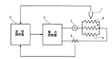
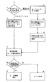
図1は、本発明の温度調節器を備える温度制御システムの構成図である。 FIG. 1 is a configuration diagram of a temperature control system including a temperature controller of the present invention.
この実施の形態の温度制御システムは、熱電対等の温度センサ1からの検出温度に基づいて、図示しない制御対象の温度が目標温度になるように、アナログの制御出力である4〜20mAの電流出力を与えるアナログ出力タイプの温度調節器2と、この温度調節器2からの電流出力に基づいて、交流電源3の位相を制御して制御対象を加熱する複数、この実施の形態では、並列接続された3本のヒータ4の通電量を制御する電力調整器5とを備えている。
The temperature control system according to this embodiment is based on the temperature detected from the temperature sensor 1 such as a thermocouple, and the current output of 4 to 20 mA, which is an analog control output, is set so that the temperature of the control target (not shown) becomes the target temperature. And an analog output
この実施の形態の温度調節器2は、上述のように、連続的な電流出力を、制御出力として電力調整器5に与えるアナログ出力タイプの温度調節器であり、かかるアナログ出力タイプの温度調節器において、ヒータ4の断線を検知できるように次のように構成している。
As described above, the
すなわち、この実施の形態の温度調節器2には、3本のヒータ4に流れる電流を検出する変流器CTを用いた電流センサ6の検出出力が与えられており、温度調節器2は、この電流センサ6で検出されたヒータ4の電流値と、電力調整器5に対する制御出力値とに基づいて、ヒータ4の断線を検知する断線検知手段を備えている。
That is, the
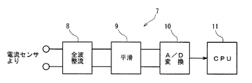
図2は、この断線検知手段の構成を示すブロック図であり、図3は、各部の信号波形図である。 FIG. 2 is a block diagram showing the configuration of this disconnection detecting means, and FIG. 3 is a signal waveform diagram of each part.
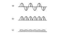
この実施の形態の断線検知手段7は、例えば、50%の制御出力値に対応する図3(a)に示される電流センサ6の出力を、全波整流する全波整流回路8と、この全波整流回路8の図3(b)に示される出力を平滑する平滑回路9と、この平滑回路9の図3(c)に示される出力を、A/D変換するA/D変換回路10と、このA/D変換回路10の出力に基づいて、後述のように断線の有無を判定するとともに、上述の温度センサ1からの検出温度と目標温度との偏差に基づいて、偏差がなくなるように制御出力を与える制御部としてのCPU11とを備えている。
The disconnection detection means 7 of this embodiment includes, for example, a full-wave rectification circuit 8 that performs full-wave rectification on the output of the
このCPU11は、後述のように検出したヒータの電流値を図示しない表示部に表示するとともに、断線が検知されたときには、エラー表示などの適宜の警報動作を行うものである。
The
電流センサ6によって検出される図3(a)に示されるヒータ4の通電電流は、CPU11から出力される制御出力値、例えば、50%、80%といった制御出力値に応じて、交流の半サイクル毎に変化するので、全波整流回路8および平滑回路9で整流平滑された出力、すなわち、ヒータ4の電流値は、制御出力値に応じて変化することになる。
The energization current of the
そこで、この実施の形態では、CPU11において、制御出力値に応じて変化するヒータ4の電流値を、予め定めた制御出力値に対応する電流値に変換し、この変換した電流値と設定値とを比較してヒータの断線の有無を判定するようにしている。すなわち、CPU11は、制御出力値に基づいて、電流センサ6で検出される電流値を、予め定めた制御出力値に対応する電流値に変換する変換部としての機能を有するとともに、変換された電流値と設定値とを比較して断線の有無を判定する比較部としての機能を備えている。
Therefore, in this embodiment, the
この実施の形態では、予め定めた制御出力値を100%としており、電流センサ6で検出された電流値を、そのときの制御出力値を用いて100%の制御出力値に対応する電流値に変換するものである。
In this embodiment, the predetermined control output value is set to 100%, and the current value detected by the
例えば、電流センサ6で検出されたヒータ4の電流値が、10Aであって、そのときの制御出力値が50%であったとすると、100%の制御出力値に対応する電流値を20Aとするものである。
For example, if the current value of the
すなわち、この実施の形態では、電流センサ6によって検出されるヒータの電流値CT0を、そのときの制御出力値OUTに基づいて、100%の制御出力値に対応する電流値CT1に次式に従って変換するものである。
That is, in this embodiment, the heater current value CT0 detected by the
CT1=(CT0/OUT)×100
例えば、電流センサ6で検出されたヒータ4の電流値が、10Aであって、そのときの制御出力値が80%であったとすると、100%の制御出力値に対応する電流値CT1は、上記式より12.5Aとなる。
CT1 = (CT0 / OUT) × 100
For example, if the current value of the
このようにして変換された電流値と、断線の有無を判定する閾値となる設定値とを比較し、設定値を下回ったときには、断線であると判定して、エラー表示などの適宜の警報動作を行うものである。 The current value thus converted is compared with a set value that becomes a threshold value for determining the presence or absence of disconnection, and when the value is lower than the set value, it is determined that there is a disconnection, and an appropriate alarm operation such as an error display is performed. Is to do.
この実施の形態では、上述のように、3本のヒータ4が並列に接続されているので、例えば、いずれのヒータ4も断線していない正常な状態における100%の制御出力値に対応する電流値よりも小さく、かつ、前記電流値の2/3倍よりも大きな電流値を、設定値としている。
In this embodiment, as described above, since the three
この実施の形態では、電流センサ6で検出されたヒータ4の電流値を、100%の制御出力値に対応する電流値に変換し、制御出力値100%に対応する設定値と比較して断線の有無を判定したけれども、本発明の他の実施の形態として、電流センサ6で検出されたヒータ4の電流値を変換することなく、例えば、100%の制御出力値に対応する設定値から、ヒータ4の電流値が検出されたときの制御出力値に対応する設定値を換算算出し、この算出した設定値とヒータ電流値とを比較して断線の有無を判定してもよい。例えば、ヒータ4の電流値が制御出力値が50%のときの電流値であるときには、100%の制御出力値に対応する設定値を、1/2倍して制御出力値50%に対応する設定値を算出し、この算出された設定値とヒータ電流値とを比較するのである。
In this embodiment, the current value of the
以上のようにしてヒータ4の通電量を電力調整器5を介して位相制御するアナログ出力タイプの温度調節器2において、ヒータ4の断線を検知することが可能となるので、例えば、セラミックヒータを用いて1秒間に100〜300℃の昇温を行うとともに、±1℃といった高精度の温度制御が要求される半導体製造装置、特に、フリップチップボンダなどの温度制御に好適である。
In the analog output
また、この実施の形態の温度調節器2は、例えば、切換え操作によって、オンオフパルスを制御出力として出力するデジタル出力タイプとして使用することもできる。この場合には、例えば、図4に示されるように、温度調節器2は、温度センサ1で検出される制御対象の温度が目標温度になるようにオンオフパルスをリレー12に出力し、ヒータ4の通電量をオンオフ制御するものである。
Moreover, the
このように温度調節器2は、アナログ出力およびデジタル出力を兼用できる、いわゆる、マルチ出力タイプの温度調節器である。
Thus, the
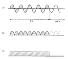
このオンオフパルスを制御出力とするデジタル出力の場合には、従来例と同様に、図5(a)に示される電流センサ6の出力を、図5(b)に示されるように全波整流し、更に、図5(c)に示されるように平滑し、この平滑出力を、オンパルスを出力しているオン期間において、サンプリングしてA/D変換して設定値と比較して断線の有無を判定するものである。
In the case of digital output using the on / off pulse as a control output, the output of the
図6は、この実施の形態の温度調節器2の断線検知の動作説明に供するフローチャートである。
FIG. 6 is a flowchart for explaining the operation of detecting disconnection of the
先ず、オンオフパルス出力(デジタル出力)であるか電流出力(アナログ出力)のいずれであるかを判断し(ステップn1)、オンオフパルス出力であるときには、従来のデジタル出力タイプの温度調節器と同様に、出力がオンしている期間に、上述のように整流平滑されたデータをサンプリングしてA/D変換して読み取り(ステップn2)、電流値に変換するとともに、変換したヒータ電流値を表示し(ステップn3)、このヒータ電流値と、ヒータ断線の閾値である設定値とを比較し(ステップn4)、ヒータの電流値が小さいときには、ヒータ断線が発生したとしてエラー表示などの適宜の警報動作を行い(ステップn5)、小さくないときには、ヒータ4は正常である判定する(ステップn9)。
First, it is determined whether the output is an on / off pulse output (digital output) or a current output (analog output) (step n1). When the output is an on / off pulse output, it is the same as a conventional digital output type temperature controller. During the period when the output is on, the data rectified and smoothed as described above is sampled, A / D converted and read (step n2), converted into a current value, and the converted heater current value is displayed. (Step n3) This heater current value is compared with a set value which is a threshold value for heater disconnection (Step n4). When the heater current value is small, an appropriate alarm operation such as an error display is given as the heater disconnection has occurred. (Step n5), if not smaller, it is determined that the
ステップn1において、電流出力であると判断されたときには、上述のように整流平滑されたデータをサンプリングしてA/D変換して読み取り(ステップn6)、電力調整器5がリニアな特性でない場合には、リニアになるようにスケーリングを行い(ステップn7)、上述の式に従って制御出力100%に対応する値に変換し(ステップn8)、電流値にして(ステップn3)設定値と比較し(ステップn4)、電流値が小さいときには、ヒータ断線が発生したとしてエラー表示などの適宜の警報動作を行い(ステップn5)、小さくないときには、ヒータ4は正常である判定する(ステップn9)。
When it is determined in step n1 that the current is output, the data rectified and smoothed as described above is sampled, A / D converted and read (step n6), and the
以上のようにしてアナログ出力タイプとしてもデジタル出力タイプとしてもヒータ4の断線を検知することができる。
As described above, the disconnection of the
この実施の形態では、ステップn3で電流値に変換する前に、ステップn8において、制御出力値100%に対応する値に変換したけれども、他の実施の形態として、電流値に変換した後に、制御出力値100%に対応する電流値に変換してもよいのは勿論である。 In this embodiment, the value is converted into a value corresponding to the control output value 100% in step n8 before being converted into the current value in step n3. However, as another embodiment, the control value is converted into the current value and then controlled. Of course, it may be converted into a current value corresponding to an output value of 100%.
(その他の実施の形態)
上述の実施の形態では、電流センサ6の出力を全波整流したけれども、半波整流でもよい。
(Other embodiments)
In the above-described embodiment, the output of the
上述の実施の形態では、ヒータ4の本数は3本であったけれども、ヒータの本数は任意である。
In the above embodiment, the number of
本発明は、温度調節器として有用である。 The present invention is useful as a temperature controller.
1 温度センサ 2 温度調節器
3 交流電源 4 ヒータ
5 電力調整器 6 電流センサ
7 断線検知手段 8 全波整流回路
9 平滑回路 10 A/D変換回路
DESCRIPTION OF SYMBOLS 1
Claims (7)
電流センサで検出される前記ヒータの電流値および前記制御出力値に基づいて、前記ヒータの断線を検知する断線検知手段を備えることを特徴とする温度調節器。 In the temperature controller that controls the energization of the heater that heats the controlled object by outputting an analog control output to the power controller,
A temperature regulator comprising: a disconnection detecting means for detecting disconnection of the heater based on a current value of the heater and a control output value detected by a current sensor.
Priority Applications (1)
| Application Number | Priority Date | Filing Date | Title |
|---|---|---|---|
| JP2003401142A JP2005166327A (en) | 2003-12-01 | 2003-12-01 | air conditioner |
Applications Claiming Priority (1)
| Application Number | Priority Date | Filing Date | Title |
|---|---|---|---|
| JP2003401142A JP2005166327A (en) | 2003-12-01 | 2003-12-01 | air conditioner |
Publications (1)
| Publication Number | Publication Date |
|---|---|
| JP2005166327A true JP2005166327A (en) | 2005-06-23 |
Family
ID=34725160
Family Applications (1)
| Application Number | Title | Priority Date | Filing Date |
|---|---|---|---|
| JP2003401142A Pending JP2005166327A (en) | 2003-12-01 | 2003-12-01 | air conditioner |
Country Status (1)
| Country | Link |
|---|---|
| JP (1) | JP2005166327A (en) |
Cited By (8)
| Publication number | Priority date | Publication date | Assignee | Title |
|---|---|---|---|---|
| JP2009070682A (en) * | 2007-09-13 | 2009-04-02 | Omron Corp | Heater control device |
| JP2010066119A (en) * | 2008-09-10 | 2010-03-25 | Omron Corp | Power regulator |
| JP2010181255A (en) * | 2009-02-05 | 2010-08-19 | Omron Corp | Disconnection detection device, control device, and power regulator |
| JP2011122863A (en) * | 2009-12-09 | 2011-06-23 | M-System Co Ltd | Signal converter |
| JP2011243307A (en) * | 2010-05-14 | 2011-12-01 | Toyota Boshoku Corp | Disconnection inspecting method |
| WO2016117375A1 (en) * | 2015-01-22 | 2016-07-28 | 株式会社デンソー | Heater device |
| JP2023023298A (en) * | 2021-08-05 | 2023-02-16 | ミツミ電機株式会社 | Power source semiconductor integrated circuit and power source regulator circuit |
| JP2023066989A (en) * | 2021-10-29 | 2023-05-16 | 株式会社ジェイテクトサーモシステム | Heater monitoring device, heat treatment device, heater monitoring method, and program |
-
2003
- 2003-12-01 JP JP2003401142A patent/JP2005166327A/en active Pending
Cited By (10)
| Publication number | Priority date | Publication date | Assignee | Title |
|---|---|---|---|---|
| JP2009070682A (en) * | 2007-09-13 | 2009-04-02 | Omron Corp | Heater control device |
| JP2010066119A (en) * | 2008-09-10 | 2010-03-25 | Omron Corp | Power regulator |
| JP2010181255A (en) * | 2009-02-05 | 2010-08-19 | Omron Corp | Disconnection detection device, control device, and power regulator |
| JP2011122863A (en) * | 2009-12-09 | 2011-06-23 | M-System Co Ltd | Signal converter |
| JP2011243307A (en) * | 2010-05-14 | 2011-12-01 | Toyota Boshoku Corp | Disconnection inspecting method |
| WO2016117375A1 (en) * | 2015-01-22 | 2016-07-28 | 株式会社デンソー | Heater device |
| JPWO2016117375A1 (en) * | 2015-01-22 | 2017-06-22 | 株式会社デンソー | Heater device |
| JP2023023298A (en) * | 2021-08-05 | 2023-02-16 | ミツミ電機株式会社 | Power source semiconductor integrated circuit and power source regulator circuit |
| JP7678302B2 (en) | 2021-08-05 | 2025-05-16 | ミツミ電機株式会社 | Power supply semiconductor integrated circuit and power supply regulator circuit |
| JP2023066989A (en) * | 2021-10-29 | 2023-05-16 | 株式会社ジェイテクトサーモシステム | Heater monitoring device, heat treatment device, heater monitoring method, and program |
Similar Documents
| Publication | Publication Date | Title |
|---|---|---|
| JP7583086B2 (en) | System and method for controlling power to a heater - Patents.com | |
| JP2005333793A (en) | Power factor compensating controller and method of inverter control circuit | |
| JP2005245097A (en) | Switching power supply, image forming apparatus, and control method thereof | |
| EP2741569B1 (en) | Heater control device, control method, and control program | |
| JP2012512618A (en) | Remote power control device | |
| JP2593416B2 (en) | Small object detection circuit of high frequency induction heating cooker | |
| JP2005166327A (en) | air conditioner | |
| JP4156756B2 (en) | Temperature control device for soldering iron | |
| US10936030B2 (en) | Method and device for controlling temperature | |
| JP2010066119A (en) | Power regulator | |
| CN118625872A (en) | Temperature control method for heating device and heating device | |
| JP6939109B2 (en) | Lighting control device, lighting equipment, lighting system | |
| JP2010122082A (en) | Fault detection circuit and electric power regulator | |
| JP6690286B2 (en) | Heating device and image forming device | |
| JP2005322560A (en) | Induction heating cooker | |
| JP2007012578A (en) | Heater disconnection detector | |
| JP2965381B2 (en) | Constant voltage control type electric heating circuit | |
| JP2005293480A (en) | Temperature controller of hot platen | |
| JPH09230740A (en) | Electric heater controller | |
| JP3823772B2 (en) | Induction heating cooker | |
| KR20210138889A (en) | AC Power Detector and Electronic Device having AC Power Detector | |
| JP2026027339A (en) | System and method for controlling power to a heater | |
| JP2006156294A (en) | Heating apparatus and image forming apparatus | |
| JP2002202687A (en) | Image forming device | |
| JP2004200179A (en) | Electric heater control device |