JP2005293480A - Temperature controller of hot platen - Google Patents
Temperature controller of hot platen Download PDFInfo
- Publication number
- JP2005293480A JP2005293480A JP2004111107A JP2004111107A JP2005293480A JP 2005293480 A JP2005293480 A JP 2005293480A JP 2004111107 A JP2004111107 A JP 2004111107A JP 2004111107 A JP2004111107 A JP 2004111107A JP 2005293480 A JP2005293480 A JP 2005293480A
- Authority
- JP
- Japan
- Prior art keywords
- power
- temperature
- output
- circuit
- temperature controller
- Prior art date
- Legal status (The legal status is an assumption and is not a legal conclusion. Google has not performed a legal analysis and makes no representation as to the accuracy of the status listed.)
- Pending
Links
- 238000006243 chemical reaction Methods 0.000 claims description 11
- 230000006698 induction Effects 0.000 abstract description 2
- 238000010438 heat treatment Methods 0.000 description 26
- 238000005259 measurement Methods 0.000 description 14
- 229910052751 metal Inorganic materials 0.000 description 6
- 239000002184 metal Substances 0.000 description 6
- 230000001939 inductive effect Effects 0.000 description 5
- 239000010445 mica Substances 0.000 description 4
- 229910052618 mica group Inorganic materials 0.000 description 4
- 238000005266 casting Methods 0.000 description 2
- 238000010586 diagram Methods 0.000 description 2
- 230000000694 effects Effects 0.000 description 2
- BASFCYQUMIYNBI-UHFFFAOYSA-N platinum Chemical compound [Pt] BASFCYQUMIYNBI-UHFFFAOYSA-N 0.000 description 2
- 229910052782 aluminium Inorganic materials 0.000 description 1
- XAGFODPZIPBFFR-UHFFFAOYSA-N aluminium Chemical compound [Al] XAGFODPZIPBFFR-UHFFFAOYSA-N 0.000 description 1
- 238000013459 approach Methods 0.000 description 1
- 239000003990 capacitor Substances 0.000 description 1
- 238000001514 detection method Methods 0.000 description 1
- 238000009499 grossing Methods 0.000 description 1
- 238000009413 insulation Methods 0.000 description 1
- 238000004519 manufacturing process Methods 0.000 description 1
- 239000000463 material Substances 0.000 description 1
- 229910052697 platinum Inorganic materials 0.000 description 1
- 239000004065 semiconductor Substances 0.000 description 1
Images

Landscapes
- Control Of Resistance Heating (AREA)
- Control Of Temperature (AREA)
Abstract
Description
本発明は、熱板の温度を制御する温度制御装置に属する。 The present invention belongs to a temperature control device that controls the temperature of a hot plate.
従来の熱板の温度制御装置としては、半導体の製造工程においてウエハーのような製品を加熱し、一定温度としてから各種の電気的特性を測定し、その製品の品質をチェックするための温度制御に用いられているものがある。熱板は、製品の加熱や、製品を一定温度に保温するための使用されている。 As a conventional temperature control device for a hot plate, a product such as a wafer is heated in a semiconductor manufacturing process, and various electrical characteristics are measured after a constant temperature, and temperature control is performed to check the quality of the product. Some are used. The hot plate is used for heating the product and keeping the product at a constant temperature.
熱板は、シーズヒータ(発熱体)を金属板にカシメ接合したもの、シーズヒータを金属板に鋳込み結合したもの、発熱線(発熱体)をマイカ板に巻着したものを金属板やセラミックス板に設けたものなどにより作られている。 The heat plate is made by caulking and bonding a sheathed heater (heating element) to a metal plate, by casting and bonding a sheathed heater to a metal plate, or by wrapping a heating wire (heating element) around a mica plate. It is made by the thing provided in.
ところで、交流電源にて発熱体に電力を通電すると、熱板を介して誘導ノイズが発生し、測定に影響をおよぼす為、測定中は発熱体への電力の通電を停止するようにしている。 By the way, when electric power is supplied to the heating element with an AC power source, inductive noise is generated through the hot plate and affects the measurement. Therefore, the electric power supply to the heating element is stopped during the measurement.
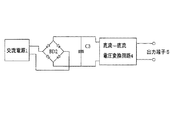
また、直流にて発熱体に電力を通電した場合には、交流の時のような誘導ノイズによる測定への影響は無いが、既存の商用電力は、全て交流となっているので交流を直流に変換する必要があり、通常は、図4に示すような構成の交流電源1に入力された交流がダイオードブリッジBD2と電圧平滑用のコンデンサC3からなる交流−直流変換器を用いて電圧変換を行い交流−直流電圧変換回路4にて直流を電圧制御され出力端子5へ出力する回路が利用され制御されている(例えば、特許文献1参照)。
In addition, when power is supplied to the heating element with direct current, there is no effect on measurement due to inductive noise as in the case of alternating current, but since all existing commercial power is alternating current, alternating current is changed to direct current. Usually, the AC input to the
しかしながら、交流電源にて発熱体に電力を通電すると、熱板を介して誘導ノイズが発生し、測定に影響をおよぼす為、測定中は発熱体への電力の通電を停止する必要がある。 However, when electric power is supplied to the heating element with an AC power supply, inductive noise is generated through the hot plate and affects the measurement. Therefore, it is necessary to stop the electric power supply to the heating element during the measurement.
直流にて発熱体に電力を通電すると、交流の時のような誘導ノイズによる測定への影響は無いが、既存の商用電力は、全て交流となっているので交流を直流に変換する必要がある。この時、発熱体の制御中は、定格となる大電流に対応する必要があるので直流変換の装置が大きくなってしまうという問題がある。 When power is supplied to the heating element with direct current, there is no effect on measurement due to inductive noise as in the case of alternating current, but since all existing commercial power is alternating current, it is necessary to convert alternating current to direct current. . At this time, during the control of the heating element, it is necessary to cope with the rated large current, which causes a problem that the DC conversion device becomes large.
また、この発熱体を一定温度で保温すると、定格となる対電流に対応した直流変換装置であると変換のロスが多く直流に変換した電力の大半を回路内での熱エネルギー損失として捨てなければならないので無駄が生じる。その結果として、交流を直流に変換すると、交流にてヒータに通電を行う時より約1.5倍の電力が必要となる。 In addition, if this heating element is kept at a constant temperature, a DC converter that can handle rated current will have much conversion loss, and most of the power converted to DC must be discarded as thermal energy loss in the circuit. It will be wasteful. As a result, when alternating current is converted to direct current, about 1.5 times as much power is required as when the heater is energized with alternating current.
それ故に本発明の課題は、誘導ノイズの影響を回避することができ、電力消費エネルギーの損失を低減できる熱板の温度制御装置を提供することにある。 Therefore, the subject of this invention is providing the temperature control apparatus of the hot plate which can avoid the influence of induction noise and can reduce the loss of power consumption energy.
本発明によれば、温度調節器と、該温度調節器に接続されているセンサと、該センサにより測定された熱板の温度を前記温度調節器から制御出力を入力する交流・直流電力出力判定回路と、交流電源に接続されて交流を直流に変換する交流・直流変換回路と、該交流・直流変換回路によって変換された直流電力を入力する直流電力調整回路と、前記交流・直流電力出力判定回路にて出力に応じて交流・直流の切り替え信号を入力する交流・直流電力出力切替回路と、前記交流電源からの交流電力を調整する交流電力調整回路とを有し、前記交流・直流電力出力判定回路により熱板に対する制御電力の種類の切替が自動的にできるよう前記センサより測定された前記熱板の温度と前記温度調節器にて設定した温度との差に応じて前記温度調節器から前記制御出力が前記交流・直流電力出力判定回路になされることを特徴とする熱板の温度制御装置が得られる。 According to the present invention, a temperature regulator, a sensor connected to the temperature regulator, and an AC / DC power output determination for inputting a control output from the temperature regulator to the temperature of the hot plate measured by the sensor. A circuit, an AC / DC conversion circuit connected to an AC power source for converting AC to DC, a DC power adjustment circuit for inputting DC power converted by the AC / DC conversion circuit, and the AC / DC power output determination An AC / DC power output switching circuit that inputs an AC / DC switching signal according to the output in the circuit, and an AC power adjustment circuit that adjusts the AC power from the AC power source, the AC / DC power output The temperature controller according to the difference between the temperature of the hot plate measured by the sensor and the temperature set by the temperature controller so that the type of control power for the hot plate can be automatically switched by the determination circuit. Temperature control of the hot plate is obtained, characterized in that al the control output is made to the AC-DC power output determining circuit.
本発明に係る熱板の温度制御装置によれば、測定を行わないある一定温度までの昇温を交流にて行い、発熱体を一定温度での保温するときに直流にて電力を制御することで、測定時における熱板を介して発生する誘導ノイズの影響を回避することができ、電力消費エネルギーの損失を低減できる。 According to the temperature control device for a hot plate according to the present invention, the temperature is raised to a certain temperature where measurement is not performed by alternating current, and the electric power is controlled by direct current when the heating element is kept at a constant temperature. Thus, it is possible to avoid the influence of inductive noise generated through the hot plate at the time of measurement, and to reduce power consumption energy loss.
本発明の熱板の温度制御装置は、温度調節器と、該温度調節器に接続されているセンサと、該センサにより測定された熱板の温度を前記温度調節器から制御出力を入力する交流・直流電力出力判定回路と、交流電源に接続されて交流を直流に変換する交流・直流変換回路と、該交流・直流変換回路によって変換された直流電力を入力する直流電力調整回路と、前記交流・直流電力出力判定回路にて出力に応じて交流・直流の切り替え信号を入力する交流・直流電力出力切替回路と、前記交流電源からの交流電力を調整する交流電力調整回路とを有し、前記センサより測定された前記熱板の温度と前記温度調節器にて設定した温度との差に応じて前記温度調節器から前記制御出力が前記交流・直流電力出力判定回路になされ、前記交流・直流電力出力判定回路により熱板に対する制御電力の種類の切替が自動的にできることにより実現した。 The temperature control device for a hot plate according to the present invention includes a temperature regulator, a sensor connected to the temperature regulator, and an alternating current for inputting a control output from the temperature regulator to the temperature of the hot plate measured by the sensor. A DC power output determination circuit, an AC / DC conversion circuit that is connected to an AC power source to convert AC to DC, a DC power adjustment circuit that inputs DC power converted by the AC / DC conversion circuit, and the AC An AC / DC power output switching circuit that inputs an AC / DC switching signal according to the output in the DC power output determination circuit, and an AC power adjustment circuit that adjusts AC power from the AC power source, According to the difference between the temperature of the hot plate measured by the sensor and the temperature set by the temperature controller, the control output from the temperature controller is made to the AC / DC power output determination circuit, and the AC / DC power output is determined. Switching of the type of control power to the hot plate was realized by it automatically by the output judging circuit.
以下、本発明に係る熱板の温度制御装置の一実施の形態例を説明する。図1は、一実施の形態例における熱板の温度制御装置を示している。 Hereinafter, an embodiment of a temperature control device for a hot plate according to the present invention will be described. FIG. 1 shows a temperature control device for a hot plate in an embodiment.
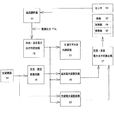
図1を参照して、熱板の温度制御装置は、温度調節器11と、温度調節器11に接続されているセンサ12と、センサ12により測定された温度を温度調節器11から制御出力11aを入力する交流・直流電力出力判定回路13と、交流電源14に接続されて交流を直流に変換する交流・直流変換回路15と、交流・直流変換回路15によって変換された直流電力を入力する直流電力調整回路16と、交流・直流電力出力判定回路13にて出力に応じて交流・直流の切り替え信号を入力する交流・直流電力出力切替回路17と、交流電源14からの交流電力を調整する交流電力調整回路20と、交流・直流電力出力判定回路13からの交流・直流の計測制可否を判定する計測可否判定外部回路21とを有している。
Referring to FIG. 1, a temperature control device for a hot plate includes a
センサ12は、白金抵抗体若しくは熱伝対などを採用しており、熱板31の温度を感知するように熱板31の所望個所に取り付けられている。熱板31は、金属板,耐熱ゴム板やマイカ板などの1種からなる加熱物31aと、この加熱物31aを加熱する発熱体32とを有している。発熱体32としては、周知なシーズヒータの他に、カートリッジヒータ、マイカ板に発熱線を巻着したものなどがある。熱板31は、シーズヒータをアルミニウム板に鋳込んだもの、金属板にシーズヒータをカシメ結合したもの、シーズヒータをHIP(熱間静水圧)により結合したもの、発熱線をマイカ板に巻着して金属板に結合したもの、発熱線を耐熱ゴム材に張り付けたものを金属板に結合したものなどがある。
The
この実施例における熱板の温度制御装置では、測定が実施される温度まで昇温を交流にて行い、発熱体32を一定温度で保温するときに直流にて電力を制御することにより、直流にて必要な電力は保温するために必要な電力となり、銃リア、必要としていた電力よりに低減できることになる。 In the temperature control device for the hot plate in this embodiment, the temperature is raised by alternating current to the temperature at which the measurement is performed, and the electric power is controlled by direct current when the heating element 32 is kept at a constant temperature, so that the direct current is obtained. Therefore, the necessary power becomes the power necessary to keep the heat, and can be reduced from the power required for the gun rear and the gun rear.
センサ12より測定された熱板31の温度と温度制御器11にて設定した温度との差に応じて温度調節器11から制御出力11a(電圧出力又は、電流出力)がなされ、交流・直流電力出力判定回路13に入力され、この交流・直流電力出力判定回路13にて制御出力11aの出力に応じて交流・直流の切り替え信号を交流・直流電力出力切替回路17へ出力する。
In accordance with the difference between the temperature of the hot plate 31 measured by the
また、交流・直流電力出力判定回路13からは、制御出力11aの出力に応じて出力が一定値以下のときは、直流電力調整器16へ、また一定値以上のときは、交流電力調整器20に温度調節器11からの制御信号11aが転送されている。この結果、発熱体32へは、交流・直流電力出力切替回路17にて切り替えられた電力が通電される。また、交流・直流電力出力判定回路13から計測可否判定外部回路21では、発熱体32への電力が直流のときに計測が可能なことを外部に出力する。
Further, from the AC / DC power
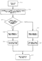
図2は、図1示した熱板の温度制御装置における動作をフローチャートによって表している。図2を参照して、まず、センサ12による温度検出を行う(ステップS1)。次に、温度調節器11によりセンサ12にて測定された温度と温度制御器11にて設定された温度との温度差により制御信号11aが行われる(ステップS2)。次に、交流・直流判定回路13によって制御出力11aが一定値以上か否かの判断を行う(ステップS3)。制御出力11aが一定値以上であれば、交流電力調整回路10へ制御出力1aを転送出力する(ステップS4)。そして、交流・直流切替回路17を交流側へ切り換える(ステップS5)。そして、発熱体32へ電力通電する(ステップS8)。
FIG. 2 is a flowchart showing the operation of the temperature control device for the hot plate shown in FIG. With reference to FIG. 2, temperature detection is first performed by the sensor 12 (step S1). Next, the control signal 11a is performed based on the temperature difference between the temperature measured by the
また、制御出力11aが一定値以下であれば、直流電力調整回路6へ制御出力1aを転送出力する(ステップS6)。そして、交流・直流切替回路17を直流側へ切り換える(ステップS7)。そして、発熱体32へ電力通電する(ステップS8)。 On the other hand, if the control output 11a is below a certain value, the control output 1a is transferred and output to the DC power adjustment circuit 6 (step S6). Then, the AC / DC switching circuit 17 is switched to the DC side (step S7). Then, power is supplied to the heating element 32 (step S8).
図3は、温度、制御出力を経過時間で示している制御チャートである。図3を参照して、温度調節器11にて設定された目標温度である目標値が150℃とすると、常温(大気温)から目標値の間近の温度まで接近した経過時間150の所で出力が切り替えられて、これ以降は直流による一定温度での保温となっている。
FIG. 3 is a control chart showing temperature and control output in elapsed time. Referring to FIG. 3, when the target value that is the target temperature set by
この保温の際には、制御出力も大きな電力を必要としない為、これに適した電力回路を作成すればよいので変換の損失が小さくなる。又、目標値をさらに高い温度たとえば200℃へ変更した場合、制御出力が再び80%以上となるのでこの時は,交流に切り替え昇温してやればよい。 At the time of this heat insulation, the control output does not require a large amount of power, so that a power circuit suitable for this need only be created, so that the conversion loss is reduced. In addition, when the target value is changed to a higher temperature, for example, 200 ° C., the control output becomes 80% or more again.
このように交流・直流の出力判定切替回路13を設けることにより、直流のみにて温度制御を行うより使用エネルギー量を削減できることとなる。
By providing the AC / DC output
11 温度調節器
11a 制御出力
12 センサ
13 交流・直流電力出力判定回路
14 交流電源
15 交流・直流変換回路
16 直流電力調整回路
17 交流・直流電力出力切替回路
20 交流電力調整回路
21 計測可否判定外部回路
31 熱板
31a 加熱物
32 発熱体
DESCRIPTION OF
Claims (1)
A temperature controller, a sensor connected to the temperature controller, an AC / DC power output determination circuit for inputting a control output from the temperature controller to a temperature of the hot plate measured by the sensor, and an AC power source AC / DC conversion circuit connected to convert AC to DC, DC power adjustment circuit for inputting DC power converted by the AC / DC conversion circuit, and the AC / DC power output determination circuit according to the output An AC / DC power output switching circuit for inputting an AC / DC switching signal, and an AC power adjustment circuit for adjusting AC power from the AC power source. The control output from the temperature controller according to the difference between the temperature of the hot plate measured by the sensor and the temperature set by the temperature controller so that the type of control power can be automatically switched. Temperature control of the hot plate, characterized in that it is made in the AC-DC power output determining circuit.
Priority Applications (1)
| Application Number | Priority Date | Filing Date | Title |
|---|---|---|---|
| JP2004111107A JP2005293480A (en) | 2004-04-05 | 2004-04-05 | Temperature controller of hot platen |
Applications Claiming Priority (1)
| Application Number | Priority Date | Filing Date | Title |
|---|---|---|---|
| JP2004111107A JP2005293480A (en) | 2004-04-05 | 2004-04-05 | Temperature controller of hot platen |
Publications (2)
| Publication Number | Publication Date |
|---|---|
| JP2005293480A true JP2005293480A (en) | 2005-10-20 |
| JP2005293480A5 JP2005293480A5 (en) | 2007-04-26 |
Family
ID=35326305
Family Applications (1)
| Application Number | Title | Priority Date | Filing Date |
|---|---|---|---|
| JP2004111107A Pending JP2005293480A (en) | 2004-04-05 | 2004-04-05 | Temperature controller of hot platen |
Country Status (1)
| Country | Link |
|---|---|
| JP (1) | JP2005293480A (en) |
Cited By (2)
| Publication number | Priority date | Publication date | Assignee | Title |
|---|---|---|---|---|
| WO2009041309A1 (en) * | 2007-09-28 | 2009-04-02 | Fujifilm Corporation | Melt extruder and process for producing thermoplastic resin film |
| JPWO2007142061A1 (en) * | 2006-06-06 | 2009-10-22 | コニカミノルタエムジー株式会社 | Microchip inspection device |
Citations (2)
| Publication number | Priority date | Publication date | Assignee | Title |
|---|---|---|---|---|
| JPH09164670A (en) * | 1995-12-15 | 1997-06-24 | Brother Ind Ltd | Inkjet printer |
| JP2004198558A (en) * | 2002-12-17 | 2004-07-15 | Ricoh Co Ltd | Image forming device |
-
2004
- 2004-04-05 JP JP2004111107A patent/JP2005293480A/en active Pending
Patent Citations (2)
| Publication number | Priority date | Publication date | Assignee | Title |
|---|---|---|---|---|
| JPH09164670A (en) * | 1995-12-15 | 1997-06-24 | Brother Ind Ltd | Inkjet printer |
| JP2004198558A (en) * | 2002-12-17 | 2004-07-15 | Ricoh Co Ltd | Image forming device |
Cited By (4)
| Publication number | Priority date | Publication date | Assignee | Title |
|---|---|---|---|---|
| JPWO2007142061A1 (en) * | 2006-06-06 | 2009-10-22 | コニカミノルタエムジー株式会社 | Microchip inspection device |
| WO2009041309A1 (en) * | 2007-09-28 | 2009-04-02 | Fujifilm Corporation | Melt extruder and process for producing thermoplastic resin film |
| JP2009083312A (en) * | 2007-09-28 | 2009-04-23 | Fujifilm Corp | Melt extrusion apparatus and method for producing thermoplastic resin film |
| CN101808799A (en) * | 2007-09-28 | 2010-08-18 | 富士胶片株式会社 | Melt extruder and process for producing thermoplastic resin film |
Similar Documents
| Publication | Publication Date | Title |
|---|---|---|
| US20200264216A1 (en) | Power converter for a thermal system | |
| EP2343952B1 (en) | Induction heating cooker | |
| EP2741569B1 (en) | Heater control device, control method, and control program | |
| JP5369773B2 (en) | Induction heating device | |
| WO2010100697A1 (en) | Induction heating device | |
| US7634209B2 (en) | Temperature control method for fixing device, and fixing device and image-forming apparatus that use the same | |
| JP3962598B2 (en) | Induction heating device | |
| JP2005293480A (en) | Temperature controller of hot platen | |
| JP2012252405A (en) | Power-supply device and image-forming device equipped with the same | |
| JPH09218720A (en) | AC controller | |
| JP2015038428A (en) | Temperature controller of furnace body for analyzer, and heat analyzer | |
| JP4285320B2 (en) | Induction heating cooker | |
| JP5369878B2 (en) | Induction heating device | |
| JP5109963B2 (en) | Induction heating cooker | |
| JP5056037B2 (en) | Induction heating rice cooker | |
| JP2004021174A (en) | Induction heating fixing device and image forming device | |
| JP5182172B2 (en) | Induction heating cooker | |
| JP2004334623A (en) | Temperature controller | |
| JP4171691B2 (en) | Heating device and temperature control method thereof | |
| JP4444126B2 (en) | Heating equipment | |
| JP5661141B2 (en) | rice cooker | |
| JP2003317916A (en) | Induction heating cooker | |
| JP5018224B2 (en) | Image forming apparatus and power conversion method | |
| JP2007121354A (en) | Heating apparatus and electrophotographic apparatus | |
| JP2004093738A (en) | Image forming device |
Legal Events
| Date | Code | Title | Description |
|---|---|---|---|
| A521 | Written amendment |
Free format text: JAPANESE INTERMEDIATE CODE: A523 Effective date: 20070312 |
|
| A621 | Written request for application examination |
Free format text: JAPANESE INTERMEDIATE CODE: A621 Effective date: 20070312 |
|
| A977 | Report on retrieval |
Free format text: JAPANESE INTERMEDIATE CODE: A971007 Effective date: 20091118 |
|
| A131 | Notification of reasons for refusal |
Effective date: 20091125 Free format text: JAPANESE INTERMEDIATE CODE: A131 |
|
| A02 | Decision of refusal |
Free format text: JAPANESE INTERMEDIATE CODE: A02 Effective date: 20100407 |