JP2005166320A - Lead acid battery - Google Patents
Lead acid battery Download PDFInfo
- Publication number
- JP2005166320A JP2005166320A JP2003400774A JP2003400774A JP2005166320A JP 2005166320 A JP2005166320 A JP 2005166320A JP 2003400774 A JP2003400774 A JP 2003400774A JP 2003400774 A JP2003400774 A JP 2003400774A JP 2005166320 A JP2005166320 A JP 2005166320A
- Authority
- JP
- Japan
- Prior art keywords
- cell
- exhaust chamber
- electrolyte
- gas discharge
- battery
- Prior art date
- Legal status (The legal status is an assumption and is not a legal conclusion. Google has not performed a legal analysis and makes no representation as to the accuracy of the status listed.)
- Granted
Links
- 239000002253 acid Substances 0.000 title claims abstract description 18
- 239000003792 electrolyte Substances 0.000 claims abstract description 39
- 239000008151 electrolyte solution Substances 0.000 claims abstract description 21
- 238000005192 partition Methods 0.000 claims description 13
- 238000010992 reflux Methods 0.000 claims description 12
- 239000007788 liquid Substances 0.000 claims description 8
- 238000005868 electrolysis reaction Methods 0.000 claims 1
- 230000002265 prevention Effects 0.000 abstract description 2
- 239000003595 mist Substances 0.000 description 5
- 230000004927 fusion Effects 0.000 description 3
- 229910000978 Pb alloy Inorganic materials 0.000 description 2
- QAOWNCQODCNURD-UHFFFAOYSA-N Sulfuric acid Chemical compound OS(O)(=O)=O QAOWNCQODCNURD-UHFFFAOYSA-N 0.000 description 2
- 239000012141 concentrate Substances 0.000 description 2
- 239000004743 Polypropylene Substances 0.000 description 1
- 230000002411 adverse Effects 0.000 description 1
- 230000015572 biosynthetic process Effects 0.000 description 1
- 230000000694 effects Effects 0.000 description 1
- 230000009191 jumping Effects 0.000 description 1
- 238000000034 method Methods 0.000 description 1
- -1 polypropylene Polymers 0.000 description 1
- 229920001155 polypropylene Polymers 0.000 description 1
- 238000000926 separation method Methods 0.000 description 1
- 239000000126 substance Substances 0.000 description 1
Images

Classifications
-
- Y—GENERAL TAGGING OF NEW TECHNOLOGICAL DEVELOPMENTS; GENERAL TAGGING OF CROSS-SECTIONAL TECHNOLOGIES SPANNING OVER SEVERAL SECTIONS OF THE IPC; TECHNICAL SUBJECTS COVERED BY FORMER USPC CROSS-REFERENCE ART COLLECTIONS [XRACs] AND DIGESTS
- Y02—TECHNOLOGIES OR APPLICATIONS FOR MITIGATION OR ADAPTATION AGAINST CLIMATE CHANGE
- Y02E—REDUCTION OF GREENHOUSE GAS [GHG] EMISSIONS, RELATED TO ENERGY GENERATION, TRANSMISSION OR DISTRIBUTION
- Y02E60/00—Enabling technologies; Technologies with a potential or indirect contribution to GHG emissions mitigation
- Y02E60/10—Energy storage using batteries
Landscapes
- Gas Exhaust Devices For Batteries (AREA)
Abstract
【課題】一括排気方式を採用した鉛蓄電池であって、ガスの排出機能に優れ、電池に振動が加わってセル内の電解液が波打ったり、電池が傾いたりしたときにも電解液の逸出を抑制した防止機能に優れた鉛蓄電池を提供する。
【解決手段】一括排気する機構を備えた鉛蓄電池において、排気室41の床壁のセルに面する壁面に前記ガス排出口を囲みセル内に向かって伸びる筒状体と電解液還流口35を囲みセル内に向かって伸びる筒状体を設け、前記ガス排出口を囲みセル内に向かって伸びる筒状体の壁面に切り欠き43または透孔を設ける。
【選択図】図3[PROBLEMS] A lead storage battery adopting a collective exhaust system, which has an excellent gas discharge function, and when the battery is vibrated and the electrolyte in the cell rips or tilts, the electrolyte is lost. Provided is a lead-acid battery having an excellent prevention function that suppresses output.
In a lead-acid battery having a mechanism for exhausting in a lump, a cylindrical body that surrounds the gas discharge port and extends toward the cell on the wall surface of the floor wall of the exhaust chamber 41 and an electrolyte solution return port 35 are provided. A cylindrical body extending toward the inside of the surrounding cell is provided, and a cutout 43 or a through hole is provided on the wall surface of the cylindrical body surrounding the gas discharge port and extending toward the inside of the cell.
[Selection] Figure 3
Description
本発明は、電解液に逸出を防止しながら、ガスを排出させる排気構造を備えた鉛蓄電池に関するものである。 The present invention relates to a lead-acid battery having an exhaust structure that discharges gas while preventing escape to an electrolytic solution.
複数のセルを備えるモノブロック式の鉛蓄電池の排気構造には、大別して、各セル毎に排気栓を設けた個別排気方式と各セルから排出されたガスを一旦排気室に導き、該排気室からガスを集中して外部に排出する一括排気方式がある。個別排気方式に比べて、一括排気方式は部品点数が少なくて済むこと、極板の上部空間の容積を小さくすることが可能であって、電池の容量を減らすことなくして電池の小型化が図れること、電解液の逸出量などの利点があるところから、車載用の鉛蓄電池に広く採用されるようになった。 The exhaust structure of a monoblock type lead-acid battery having a plurality of cells is roughly divided into an individual exhaust system in which an exhaust plug is provided for each cell, and a gas exhausted from each cell is temporarily guided to the exhaust chamber. There is a batch exhaust system that concentrates gas from the exhaust and discharges it to the outside. Compared to the individual exhaust system, the collective exhaust system requires fewer parts and the volume of the upper space of the electrode plate can be reduced, and the battery can be reduced in size without reducing the capacity of the battery. In addition, since it has advantages such as the amount of electrolyte escape, it has come to be widely adopted for in-vehicle lead acid batteries.
従来、鉛蓄電池の一括排気に関しては、電解液がミストまたは蒸気の形で電池外へ逸出するのを防ぎ、電池の内圧が上昇しないようにガスをスムースに排出させる点で幾つかの提案がされている。例えば、排気室内で電解液のミストや蒸気を含んだガスを水平方向に流し、この間に電解液のミストや蒸気を結露させることによりガスと電解液を分離、ガスを外部に排出すると共に、結露した電解液をセル内に還流する構造となっている。(特許文献1、特許文献2参照)
また、ガスと電解液の分離の効率を高めるために、前記ガスが水平方向に流れる距離を出来るだけ長くした一括排気の構造が提案されている。(特許文献3参照)
また、排気室から電池外部に至るガス排出口に多孔性フィルターを配置し、電解液のミストや蒸気が排出されるのを防ぐと共に、フィルターの下側に空間を設けてフィルターが電解液で濡れて目詰まりするのを防いだ排気構造が提案されている。(特許文献4参照)
本発明は、一括排気方式を採用した従来の鉛蓄電池の欠点に鑑みなされたものであって、ガスの排出機能、電解液の逸出防止機能に優れた鉛蓄電池を提供せんとするものである。 The present invention has been made in view of the drawbacks of conventional lead-acid batteries that employ a batch exhaust system, and is intended to provide a lead-acid battery that is excellent in gas discharge function and electrolyte escape prevention function. .
本発明においては、鉛蓄電池の排気構造を以下の構成とすることによって前記課題を解決する。
(1)本発明に係る鉛蓄電池は、複数のセルを収納する電槽と、該電槽の上面を覆う中蓋、該中蓋の凹部を覆う上蓋4囲まれれた空間に、隔壁で区画された前記複数のセル同数の排気室および該排気室に連通する少なくとも1個の集中排気室を備え、排気室の床壁に前記セルと排気室を連通するガス排気口と電解液還流口を備え、前記セルから発生するガスを前記排気室および集中排気室を経由して電池外へ一括排気する機構を備えた鉛蓄電池において、前記排気室の床壁のセルに面する壁面に前記ガス排出口を囲みセル内に向かって伸びる筒状体と電解液還流口を囲みセル内に向かって伸びる筒状体を設け、前記ガス排出口を囲みセル内に向かって伸びる筒状体の壁面に切り欠きまたは透孔を設けたことを特徴とする鉛蓄電池である。
(2)本発明に係る鉛蓄電池は、前記(1)に記載の蓄電池において、前記ガス排出口を長円形又は長方形の開口としたことを特徴とする鉛蓄電池である。
(3)本発明に係る鉛蓄電池は、前記(1)または(2)に記載の蓄電池において、前記排気室床壁のうち、前記ガス排出口を設けた局所床壁を、その周囲床壁に比べてセルの電解液面から遠い位置に配置したことを特徴とする鉛蓄電池である。
In this invention, the said subject is solved by making the exhaust structure of a lead storage battery into the following structures.
(1) A lead storage battery according to the present invention is partitioned by a partition wall into a space surrounded by a battery case housing a plurality of cells, an inner lid covering the upper surface of the battery case, and an
(2) The lead storage battery according to the present invention is the lead storage battery according to (1), wherein the gas discharge port is an oval or rectangular opening.
(3) The lead storage battery according to the present invention is the storage battery according to (1) or (2) described above, wherein a local floor wall provided with the gas discharge port is provided as a surrounding floor wall in the exhaust chamber floor wall. Compared with the electrolytic solution surface of the cell, the lead-acid battery is characterized in that it is disposed at a position far from the cell.
前記(1)および(3)に記載の本発明電池によれば、セル内の電解液面が波打ったり、電池が傾いたりした場合にも電解液の漏出の虞の小さい一括排気方式の鉛蓄電池とすることができる。
前記(2)、(3)に記載の本発明電池によれば、ガス排出口が電解液や異物で塞がれ難くでき、セルから排気室にスムースにガスを移行させることのできる鉛蓄電池とすることができる。
According to the battery of the present invention described in the above (1) and (3), the lead of the collective exhaust system with a small risk of leakage of the electrolyte even when the electrolyte surface in the cell is wavy or the battery is inclined. It can be set as a storage battery.
According to the battery of the present invention described in the above (2) and (3), the lead storage battery can make the gas discharge port difficult to be blocked by the electrolyte or foreign matter, and can smoothly transfer the gas from the cell to the exhaust chamber. can do.
以下、本発明の詳細について、1実施形態により説明するが、本発明はこれに限定されるものではない。
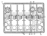
図1は、上蓋を外した状態での本発明の1実施形態に係る6セルモノブロック型の鉛蓄電池1を斜め上から見た斜視図である。2は電槽で、その内部は、電池の側辺のうち短辺に平行に配置された5個の隔壁(図示せず)によって6セルに分割されており、それぞれのセルに1組の正極板、負極板およびセパレータからなる極板群と希硫酸からなる電解液(図示せず)を収納している。図1の3は、電槽2の上に装着した中蓋で、4は、中蓋3の凹部に装着する上蓋である。電槽2、中蓋3、上蓋4は、何れもポリプロピレン製の成形体であり、電槽1の側壁上端(図示せず)と中蓋2の側壁下端(図示せず)および中蓋3の凹部に設けたの隔壁の上端と上蓋の隔壁の下端(図示せず)は熱融着されて、それぞれ気密に接合されている。なお5は、鉛合金製の正極端子、6は、鉛合金製の負極端子である。
Hereinafter, the details of the present invention will be described with reference to one embodiment, but the present invention is not limited thereto.
FIG. 1 is a perspective view of a 6-cell monoblock type lead-acid battery 1 according to an embodiment of the present invention with the top cover removed, as viewed obliquely from above. Reference numeral 2 denotes a battery case, the interior of which is divided into 6 cells by 5 partition walls (not shown) arranged in parallel to the short side of the side of the battery, and one set of positive electrodes for each cell. An electrode plate group consisting of a plate, a negative electrode plate and a separator and an electrolyte solution (not shown) consisting of dilute sulfuric acid are housed. In FIG. 1, 3 is an inner lid mounted on the
図2は、前記中蓋3をセルに面する方向から見た図である。斜線を施した部分は電槽2の側壁およびセル間隔壁(図示せず)の開口端面と熱融着によって接合される側壁31の端面と隔壁の32の端面である。電池は5個の隔壁32によって6個のセルに区画されている。中蓋3の床壁33にはセル数と同数のガス排出口34および電解液還流口中35からなる開口を設け、該開口を介してセルと排気室を連通している。
FIG. 2 is a view of the
中蓋3の床壁33のセルに面する壁面には、前記ガス排出口34を囲みセルの方向に向かって伸びる筒状体36、電解液還流口35を囲みセルに向かって伸びる筒状体37を配置している。
On the wall surface of the
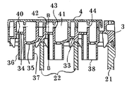
図3は、前記図2に示した中蓋3を図のA−Aで切断したときの断面図である。尚、理解し易いように、図3には、電槽2の側壁21、セル間隔壁22の開口端部と上蓋4の一部を図示した。中蓋の床壁33のうちセルに面する壁面に設けた隔壁の端面と電槽2の側壁21、セル間隔壁22の開口端部とは熱融着により気密に接合される。また、中蓋の床壁33の上面凹部に設けた隔壁と上蓋4の内面(図では下側の面)に設けた隔壁とは熱融着により気密に接合され、中蓋3と上蓋4とで囲まれた排気室41が形成される。セルから発生したガスは、ガス排出口を通って小室42に至り、上蓋4の隔壁に設けた切り欠き43を通って排気室41に移行した後、該排気室41に連通する集中排気室(図示せず)に導かれ、集中排気室を経由して電池の外へ排出される。ガスが排気室41内を移行している間にガスに混入した電解液のミストや蒸気が結露して液体となり、電解液還流口35を通って排気室41からセル内に還流される。
FIG. 3 is a cross-sectional view of the
前記のように、中蓋の床壁33にはガス排出口34を囲みセルに向かって伸びる筒状体36と電解液還流口35を囲みセルに向かって伸びる筒状体37を設けている。該筒状体は、セル内の電解液面が波打ったときには波の頂点(波頭)や波が電槽の壁面に衝突する事によって生じる電解液の飛沫がガス排出口34や電解液還流口35に至るのを防ぐ働きをする。
As described above, the
また、前記筒状体36、37の下端38をセルの電解液に浸る(筒状体36、37の下端38が電解液面の下にある状態)ように設定することによって、電解液面を小面積に区画し、電池が傾いたときに電解液がガス排出口34や電解液還流口35に至るのを抑制する働きがある。筒状体36、および筒状体37の太さや断面形状は特に限定されるものではないが、電池が傾いたときに電解液がガス排出口34や電解液還流口35に至るのを抑制するためには、電解液面をできるだけ小面積に区画することが望ましく、それには筒状体36、37の太さが小さいほうが好ましい。
In addition, by setting the
本発明においては、ガス排出口34を囲みセルに向かって伸びる筒状体36の壁面に切り欠きまたは透孔39を設けることが好ましい。該切り欠きや透孔39の大きさや位置は特に限定される者ではないが、前記のように電解液が波打ったときに電解液がガス排出口34に至るのを防ぐには、小さい方が好ましい。ただし、セルからガスをスムースに排出させるには、セル内の電解液が波打ったり、電池が傾いたりした場合にも切り欠き39の上端が電解液面の上にあることが望ましい。さらに、筒状体が電解液で濡れたときに電解液が液膜を形成して切り欠や透孔39を塞がない大きさにすることが好ましい。このような条件を満たすには、筒状体36に設ける切り欠きや透孔39は縦長の形状にすることが好ましい。このことによって、切り欠きや透孔39の上端を電解液面の上に設定し、かつ、できるだけ細くして電解液が波打ったときに電解液がガス排出口34に至るのを防ぐと同時に切り欠きや透孔39が電解液の液膜で塞がれるのを抑制することができる。
In the present invention, it is preferable to provide a notch or a
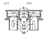
図4は、図3のB−Bで示した部分の断面図である。前記のように筒状体36の壁面には縦長の切り欠きや透孔39を設けている。
FIG. 4 is a cross-sectional view taken along the line BB in FIG. As described above, the vertically long notch and the through
本発明においては、前記のようにガス排出口34を囲みセルに向かって伸びる筒状体36の壁面に切り欠きや透孔39を設けるので電解液還流口35に比べて電解液面が波打った時に電解液飛沫がガス排出口34に到達し易い。ガス排出口34に至った電解液飛沫は、ガス排出口34に液膜を形成し塞ぐことがある。ガス配排出口が液膜で塞がれ、その上に結露した電解液が溜まるとガス排出口34を通ってセルからガスが排出34するのを阻害する虞がある。液膜の形成を防ぐためには、図3に示したようにガス排出口34の形状を円や誠正方形ではなく細長い長円形や長方形とすることが好ましい。
In the present invention, as described above, the notch and the through
また、ガス排出口34に液膜が形成してガス排出口34が塞がれることやガス排出口34に電解液面に浮遊している異物(極板から脱落したスポンジ状鉛等)詰まるという弊害を避けるために、図3および図4に示したようにガス排出口34を含む局所床壁40を中蓋の床壁33に比べて高い位置に配置してガス排出口34と電解液面との距離を大きくすることがさらに好ましい。
In addition, a liquid film is formed at the
また、中蓋の床壁33に設けたガス排出口34を備える前記局所床壁40を取り囲むように隔壁43を設け、小室42を区画し、排気室41内で結露した電解液が小室42に入り込まないようにすると同時に、セルから排出されたガスが上蓋4の隔壁43に設けた切り欠き44を通って排気室41に移行させることが好ましい。
In addition, a
3 中蓋
4 上蓋
33 排気室床壁
34 ガス排出口
35 電解液還流口
35、37 筒状体
40 局所床壁
41 排気室
3
Claims (3)
The local floor wall provided with the gas discharge port in the exhaust chamber floor wall is disposed at a position farther from the electrolyte surface of the cell than the surrounding floor wall. 2. A lead acid battery described in l.
Priority Applications (1)
| Application Number | Priority Date | Filing Date | Title |
|---|---|---|---|
| JP2003400774A JP4715091B2 (en) | 2003-11-28 | 2003-11-28 | Lead acid battery |
Applications Claiming Priority (1)
| Application Number | Priority Date | Filing Date | Title |
|---|---|---|---|
| JP2003400774A JP4715091B2 (en) | 2003-11-28 | 2003-11-28 | Lead acid battery |
Publications (3)
| Publication Number | Publication Date |
|---|---|
| JP2005166320A true JP2005166320A (en) | 2005-06-23 |
| JP2005166320A5 JP2005166320A5 (en) | 2006-10-26 |
| JP4715091B2 JP4715091B2 (en) | 2011-07-06 |
Family
ID=34724911
Family Applications (1)
| Application Number | Title | Priority Date | Filing Date |
|---|---|---|---|
| JP2003400774A Expired - Fee Related JP4715091B2 (en) | 2003-11-28 | 2003-11-28 | Lead acid battery |
Country Status (1)
| Country | Link |
|---|---|
| JP (1) | JP4715091B2 (en) |
Cited By (8)
| Publication number | Priority date | Publication date | Assignee | Title |
|---|---|---|---|---|
| JP2005216815A (en) * | 2004-02-02 | 2005-08-11 | Furukawa Battery Co Ltd:The | Liquid port plug for storage battery |
| JP2008117582A (en) * | 2006-11-02 | 2008-05-22 | Furukawa Battery Co Ltd:The | Exhaust structure of storage battery |
| JP2008186690A (en) * | 2007-01-30 | 2008-08-14 | Gs Yuasa Corporation:Kk | Lead acid storage battery |
| JP2009021017A (en) * | 2007-07-10 | 2009-01-29 | Furukawa Battery Co Ltd:The | Storage battery |
| WO2010035407A1 (en) * | 2008-09-26 | 2010-04-01 | パナソニック株式会社 | Lead acid battery manufacturing method and lead acid battery |
| CN106486616A (en) * | 2015-09-01 | 2017-03-08 | 株式会社杰士汤浅国际 | Lead battery |
| CN114243201A (en) * | 2021-12-20 | 2022-03-25 | 风帆(扬州)有限责任公司 | High valve accuse non-maintaining battery of security |
| JP7470490B2 (en) | 2018-07-27 | 2024-04-18 | 株式会社Gsユアサ | Lead-acid battery |
Citations (5)
| Publication number | Priority date | Publication date | Assignee | Title |
|---|---|---|---|---|
| JPS5298936A (en) * | 1976-02-13 | 1977-08-19 | Miyagawa Kasei Ind | Molded article and method of molding same |
| JPS6252854A (en) * | 1985-08-30 | 1987-03-07 | ジ−エヌビ− インコ−ポレイテイド | Storage battery having vent port unit |
| JPH0822815A (en) * | 1994-07-07 | 1996-01-23 | Yuasa Corp | Exhaust mechanism of storage battery |
| JP2002313317A (en) * | 2001-04-11 | 2002-10-25 | Matsushita Electric Ind Co Ltd | Liquid port stopper for storage battery and storage battery provided with the liquid port stopper for storage battery |
| JP2002540567A (en) * | 1999-03-22 | 2002-11-26 | グローリー ウィン インターナショナル グループ リミティド | Ventilation system for battery |
-
2003
- 2003-11-28 JP JP2003400774A patent/JP4715091B2/en not_active Expired - Fee Related
Patent Citations (5)
| Publication number | Priority date | Publication date | Assignee | Title |
|---|---|---|---|---|
| JPS5298936A (en) * | 1976-02-13 | 1977-08-19 | Miyagawa Kasei Ind | Molded article and method of molding same |
| JPS6252854A (en) * | 1985-08-30 | 1987-03-07 | ジ−エヌビ− インコ−ポレイテイド | Storage battery having vent port unit |
| JPH0822815A (en) * | 1994-07-07 | 1996-01-23 | Yuasa Corp | Exhaust mechanism of storage battery |
| JP2002540567A (en) * | 1999-03-22 | 2002-11-26 | グローリー ウィン インターナショナル グループ リミティド | Ventilation system for battery |
| JP2002313317A (en) * | 2001-04-11 | 2002-10-25 | Matsushita Electric Ind Co Ltd | Liquid port stopper for storage battery and storage battery provided with the liquid port stopper for storage battery |
Cited By (11)
| Publication number | Priority date | Publication date | Assignee | Title |
|---|---|---|---|---|
| JP2005216815A (en) * | 2004-02-02 | 2005-08-11 | Furukawa Battery Co Ltd:The | Liquid port plug for storage battery |
| JP2008117582A (en) * | 2006-11-02 | 2008-05-22 | Furukawa Battery Co Ltd:The | Exhaust structure of storage battery |
| JP2008186690A (en) * | 2007-01-30 | 2008-08-14 | Gs Yuasa Corporation:Kk | Lead acid storage battery |
| JP2009021017A (en) * | 2007-07-10 | 2009-01-29 | Furukawa Battery Co Ltd:The | Storage battery |
| WO2010035407A1 (en) * | 2008-09-26 | 2010-04-01 | パナソニック株式会社 | Lead acid battery manufacturing method and lead acid battery |
| US9059482B2 (en) | 2008-09-26 | 2015-06-16 | Panasonic Intellectual Property Management Co., Ltd. | Lead acid battery manufacturing method and lead acid battery |
| CN106486616A (en) * | 2015-09-01 | 2017-03-08 | 株式会社杰士汤浅国际 | Lead battery |
| CN106486616B (en) * | 2015-09-01 | 2021-03-30 | 株式会社杰士汤浅国际 | Lead-acid battery |
| JP7470490B2 (en) | 2018-07-27 | 2024-04-18 | 株式会社Gsユアサ | Lead-acid battery |
| CN114243201A (en) * | 2021-12-20 | 2022-03-25 | 风帆(扬州)有限责任公司 | High valve accuse non-maintaining battery of security |
| CN114243201B (en) * | 2021-12-20 | 2023-11-17 | 风帆(扬州)有限责任公司 | High valve accuse maintenance-free battery of security |
Also Published As
| Publication number | Publication date |
|---|---|
| JP4715091B2 (en) | 2011-07-06 |
Similar Documents
| Publication | Publication Date | Title |
|---|---|---|
| JP4715089B2 (en) | Lead acid battery | |
| US4486516A (en) | Low silhouette venting system for electric storage battery | |
| US4117205A (en) | Electric storage battery | |
| JP2002540567A (en) | Ventilation system for battery | |
| JP2015002166A (en) | Lead storage battery | |
| JP5245335B2 (en) | Lead acid battery | |
| US6686720B2 (en) | Vented-type leak resistant motor cycle battery | |
| JPWO2008016144A1 (en) | Lead acid battery | |
| JP5396161B2 (en) | Storage battery | |
| JP2020017461A (en) | Lead storage battery | |
| JP2005166318A5 (en) | ||
| JP4715091B2 (en) | Lead acid battery | |
| WO2006129340A1 (en) | Lead battery | |
| JP2009016063A (en) | Storage battery | |
| US10741803B2 (en) | Battery cover for retention of dielectric fluid | |
| JP2008186690A (en) | Lead acid storage battery | |
| JP4246600B2 (en) | Battery exhaust structure | |
| JP2015022997A (en) | Lead acid power storage battery | |
| EP0107469B1 (en) | Low silhouette venting system for electric storage battery | |
| JP4715090B2 (en) | Lead acid battery | |
| JP5145707B2 (en) | Lead acid battery | |
| JP2019029069A (en) | Lead acid battery | |
| JP5184000B2 (en) | Storage battery exhaust structure | |
| JP2008177042A (en) | Double-lid exhaust structure for storage battery | |
| JP7210925B2 (en) | lead acid battery |
Legal Events
| Date | Code | Title | Description |
|---|---|---|---|
| A711 | Notification of change in applicant |
Free format text: JAPANESE INTERMEDIATE CODE: A712 Effective date: 20051219 |
|
| A521 | Request for written amendment filed |
Free format text: JAPANESE INTERMEDIATE CODE: A523 Effective date: 20060125 |
|
| A521 | Request for written amendment filed |
Free format text: JAPANESE INTERMEDIATE CODE: A523 Effective date: 20060912 |
|
| A621 | Written request for application examination |
Free format text: JAPANESE INTERMEDIATE CODE: A621 Effective date: 20061019 |
|
| A977 | Report on retrieval |
Free format text: JAPANESE INTERMEDIATE CODE: A971007 Effective date: 20090911 |
|
| A711 | Notification of change in applicant |
Free format text: JAPANESE INTERMEDIATE CODE: A712 Effective date: 20100507 |
|
| A131 | Notification of reasons for refusal |
Free format text: JAPANESE INTERMEDIATE CODE: A131 Effective date: 20100713 |
|
| A521 | Request for written amendment filed |
Free format text: JAPANESE INTERMEDIATE CODE: A523 Effective date: 20100913 |
|
| A131 | Notification of reasons for refusal |
Free format text: JAPANESE INTERMEDIATE CODE: A131 Effective date: 20101109 |
|
| A521 | Request for written amendment filed |
Free format text: JAPANESE INTERMEDIATE CODE: A523 Effective date: 20101229 |
|
| TRDD | Decision of grant or rejection written | ||
| A01 | Written decision to grant a patent or to grant a registration (utility model) |
Free format text: JAPANESE INTERMEDIATE CODE: A01 Effective date: 20110301 |
|
| A61 | First payment of annual fees (during grant procedure) |
Free format text: JAPANESE INTERMEDIATE CODE: A61 Effective date: 20110314 |
|
| R150 | Certificate of patent or registration of utility model |
Ref document number: 4715091 Country of ref document: JP Free format text: JAPANESE INTERMEDIATE CODE: R150 Free format text: JAPANESE INTERMEDIATE CODE: R150 |
|
| FPAY | Renewal fee payment (event date is renewal date of database) |
Free format text: PAYMENT UNTIL: 20140408 Year of fee payment: 3 |
|
| LAPS | Cancellation because of no payment of annual fees |