JP2005166318A - Lead acid battery - Google Patents
Lead acid battery Download PDFInfo
- Publication number
- JP2005166318A JP2005166318A JP2003400769A JP2003400769A JP2005166318A JP 2005166318 A JP2005166318 A JP 2005166318A JP 2003400769 A JP2003400769 A JP 2003400769A JP 2003400769 A JP2003400769 A JP 2003400769A JP 2005166318 A JP2005166318 A JP 2005166318A
- Authority
- JP
- Japan
- Prior art keywords
- exhaust chamber
- chamber
- exhaust
- partition wall
- wall
- Prior art date
- Legal status (The legal status is an assumption and is not a legal conclusion. Google has not performed a legal analysis and makes no representation as to the accuracy of the status listed.)
- Granted
Links
- 239000002253 acid Substances 0.000 title claims description 33
- 238000005192 partition Methods 0.000 claims description 132
- 230000023402 cell communication Effects 0.000 claims description 40
- 239000003792 electrolyte Substances 0.000 claims description 36
- 239000007788 liquid Substances 0.000 claims description 23
- 238000002347 injection Methods 0.000 claims description 20
- 239000007924 injection Substances 0.000 claims description 20
- 238000004891 communication Methods 0.000 claims description 6
- 230000002093 peripheral effect Effects 0.000 claims description 6
- 238000010992 reflux Methods 0.000 claims description 5
- 230000001154 acute effect Effects 0.000 claims description 4
- 230000007246 mechanism Effects 0.000 claims description 2
- 238000007789 sealing Methods 0.000 claims description 2
- 229920005992 thermoplastic resin Polymers 0.000 claims description 2
- 239000008151 electrolyte solution Substances 0.000 description 18
- 239000003595 mist Substances 0.000 description 8
- 238000000034 method Methods 0.000 description 6
- XLYOFNOQVPJJNP-UHFFFAOYSA-N water Substances O XLYOFNOQVPJJNP-UHFFFAOYSA-N 0.000 description 3
- 229910000978 Pb alloy Inorganic materials 0.000 description 2
- 239000004743 Polypropylene Substances 0.000 description 2
- QAOWNCQODCNURD-UHFFFAOYSA-N Sulfuric acid Chemical compound OS(O)(=O)=O QAOWNCQODCNURD-UHFFFAOYSA-N 0.000 description 2
- 230000004888 barrier function Effects 0.000 description 2
- 230000008901 benefit Effects 0.000 description 2
- 239000012141 concentrate Substances 0.000 description 2
- 238000007599 discharging Methods 0.000 description 2
- 238000005868 electrolysis reaction Methods 0.000 description 2
- 230000004927 fusion Effects 0.000 description 2
- -1 polypropylene Polymers 0.000 description 2
- 229920001155 polypropylene Polymers 0.000 description 2
- 239000000919 ceramic Substances 0.000 description 1
- 238000009833 condensation Methods 0.000 description 1
- 230000005494 condensation Effects 0.000 description 1
- 230000012447 hatching Effects 0.000 description 1
- 230000001771 impaired effect Effects 0.000 description 1
- 230000009191 jumping Effects 0.000 description 1
- 230000005012 migration Effects 0.000 description 1
- 238000013508 migration Methods 0.000 description 1
- 230000002265 prevention Effects 0.000 description 1
- 230000008569 process Effects 0.000 description 1
- 238000000926 separation method Methods 0.000 description 1
- 238000000638 solvent extraction Methods 0.000 description 1
- 238000005728 strengthening Methods 0.000 description 1
- 238000005406 washing Methods 0.000 description 1
Images
Classifications
-
- Y—GENERAL TAGGING OF NEW TECHNOLOGICAL DEVELOPMENTS; GENERAL TAGGING OF CROSS-SECTIONAL TECHNOLOGIES SPANNING OVER SEVERAL SECTIONS OF THE IPC; TECHNICAL SUBJECTS COVERED BY FORMER USPC CROSS-REFERENCE ART COLLECTIONS [XRACs] AND DIGESTS
- Y02—TECHNOLOGIES OR APPLICATIONS FOR MITIGATION OR ADAPTATION AGAINST CLIMATE CHANGE
- Y02E—REDUCTION OF GREENHOUSE GAS [GHG] EMISSIONS, RELATED TO ENERGY GENERATION, TRANSMISSION OR DISTRIBUTION
- Y02E60/00—Enabling technologies; Technologies with a potential or indirect contribution to GHG emissions mitigation
- Y02E60/10—Energy storage using batteries
Landscapes
- Gas Exhaust Devices For Batteries (AREA)
Abstract
【課題】一括排気方式を採用した鉛蓄電池であって、ガスの排出機能、電解液の逸出防止機能に優れ、さらに電池を横転させたときにも電解液が漏出することのない鉛蓄電池を提供する。
【解決手段】一括排気する機構を備えた鉛蓄電池において、ガス排出口34と電解液還流口33とで構成された開口をとり囲む隔壁32'32''を配置し、該隔壁によって前記排気室37と区画したセル連通小室35を備え、該セル連通小室を隔壁に設けた切り欠きを介して排気室に連通させ、該切り欠き以外は隔壁によってセル連通小室と排気室を隔離する。
【選択図】 図2A lead storage battery adopting a collective exhaust system, which has an excellent gas discharge function and an electrolytic solution escape prevention function, and does not leak even when the battery is rolled over. provide.
In a lead storage battery having a mechanism for exhausting collectively, a partition wall 32'32 '' surrounding an opening constituted by a gas discharge port 34 and an electrolyte solution reflux port 33 is disposed, and the exhaust chamber is formed by the partition wall. 37 is provided with a cell communication small chamber 35 that communicates with the exhaust chamber through a notch provided in the partition wall, and the cell communication small chamber and the exhaust chamber are separated by the partition except for the notch.
[Selection] Figure 2
Description
本発明は、電解液に逸出を防止しながら、ガスを排出させる排気構造を備えた鉛蓄電池に関するものである。 The present invention relates to a lead-acid battery having an exhaust structure that discharges gas while preventing escape to an electrolytic solution.
複数のセルを備えるモノブロック式の鉛蓄電池の排気構造には、大別して、各セル毎に排気栓を設けた個別排気方式と各セルから排出されたガスを一旦排気室に導き、該排気室からガスを集中して外部に排出する一括排気方式がある。個別排気方式に比べて、一括排気方式は部品点数が少なくて済むこと、極板の上部空間の容積を小さくすることが可能であって、電池の容量を減らすことなくして電池の小型化が図れること、電解液の逸出量などの利点があるところから、車載用の鉛蓄電池に広く採用されるようになった。 The exhaust structure of a monoblock type lead-acid battery having a plurality of cells is roughly divided into an individual exhaust system in which an exhaust plug is provided for each cell, and a gas exhausted from each cell is temporarily guided to the exhaust chamber. There is a batch exhaust system that concentrates gas from the exhaust and discharges it to the outside. Compared to the individual exhaust system, the collective exhaust system requires fewer parts and the volume of the upper space of the electrode plate can be reduced, and the battery can be reduced in size without reducing the capacity of the battery. In addition, since it has advantages such as the amount of electrolyte escape, it has come to be widely adopted for in-vehicle lead acid batteries.
従来、鉛蓄電池の一括排気に関しては、電解液がミストまたは蒸気の形で電池外へ逸出するのを防ぎ、電池の内圧が上昇しないようにガスをスムースに排出させる点で幾つかの提案がされている。例えば、排気室内で電解液のミストや蒸気を含んだガスを水平方向に流し、この間に電解液のミストや蒸気を結露させることによりガスと電解液を分離、ガスを外部に排出すると共に、結露した電解液をセル内に還流する構造となっている。(特許文献1、特許文献2参照)
また、ガスと電解液の分離の効率を高めるために、前記ガスが水平方向に流れる距離を出来るだけ長くした一括排気の構造が提案されている。(特許文献3参照)
また、排気室から電池外部に至るガス排出口に多孔性フィルターを配置し、電解液のミストや蒸気が排出されるのを防ぐと共に、フィルターの下側に空間を設けてフィルターが電解液で濡れて目詰まりするのを防いだ排気構造が提案されている。(特許文献4参照)
本発明は、一括排気方式を採用した従来の鉛蓄電池の欠点に鑑みなされたものであって、ガスの排出機能、電解液の逸出防止機能に優れ、さらに電池を横転させたときにも電解液が漏出することのない鉛蓄電池を提供せんとするものである。 The present invention was made in view of the shortcomings of conventional lead-acid batteries adopting a collective exhaust system, and is excellent in gas discharge function and electrolyte escape prevention function. It is intended to provide a lead-acid battery that does not leak liquid.
本発明においては、鉛蓄電池の排気構造を以下の構成とすることによって前記課題を解決する。
(1)本発明に係る鉛蓄電池は、複数のセルを収納する電槽2と、該電槽2の上面を覆う中蓋3と、該中蓋3の凹部を覆う上蓋4に囲まれた空間に、前記空間を排気室間隔壁32で分割して前記セル数と同数の排気室37を設け、隣合う排気室同士を前記排気室間隔壁32に設けた切り欠きまたは透孔52を介して連通させ、排気室37とセルを中蓋の床壁62に設けたガス排出口34と電解液還流口33とで構成された開口を介して連通し、該排気室37に連通する集中排気室45を備え、前記セルから発生するガスを、前記排気室37に導いた後、前記集中排気室45を経由して電池外へ一括排気する機構を備えた鉛蓄電池1において、前記ガス排出口34と電解液還流口33とで構成された開口をとり囲む隔壁32′を配置し、該隔壁32′によって前記排気室37と区画したセル連通小室35を備え、該セル連通小室35を隔壁32′に設けた切り欠き36を介して排気室に連通させ、該切り欠き36以外は隔壁32′によってセル連通小室35と排気室37を隔離したことを特徴とする鉛蓄電池である。
(2)本発明に係る鉛蓄電池は、前記(1)に記載の蓄電池において、前記排気室37の床壁62が、セル連通小室35との連通部からの距離が小さい程低く、セル連通小室35との連通部からの距離が大きくなるに従って高くなるように傾斜を備え、前記排気室37は、少なくとも2つの隔壁(隔壁41、42)によって、3つ以上の排気小室(排気小室38、39、40)に分割され、該隔壁(隔壁41、42)は少なくとも1個の切り欠きを備えており、隣合う排気小室同士は、前記隔壁(隔壁41、42)に設けた切り欠き(切り欠き43、44)によって連通し、該切り欠き(切り欠き43、44)以外は前記隔壁(隔壁41、42)によって隔離され、隣合う隔壁に設けた前記切り欠き(切り欠き43、44)を、床壁62の傾斜に対してジグザグの位置に配置したことを特徴とする鉛蓄電池である。
(3)本発明に係る鉛蓄電池は、前記(2)に記載の蓄電池において、前記排気室を排気小室(排気小室38、39、40)に分割する隔壁(隔壁41、42)が、床面の傾斜に対して斜行しており、該隔壁(隔壁41、42)と排気室間隔壁32とのなす角度θが鋭角であり、該隔壁(隔壁41、42)のうち床壁62の最も低い位置に切り欠き(切り欠き43、44)を設けたことを特徴とする鉛蓄電池である。
(4)本発明に係る鉛蓄電池は、前記(2)、(3)に記載の蓄電池において、前記複数の排気室37のうち、電池の両端部に位置する排気室の少なくとも一つの排気室と隣接する位置に集中排気室45を配置し、前記排気室37と集中排気室45を隔壁32″で区画し、該隔壁32″に設けた切り欠きまたは透孔46によって、前記セル連通小室35と最も離れた排気小室40と集中排気室45を連通させ、該切り欠きまたは透孔46以外は隔壁によって排気室37と集中排気室45を隔離したことを特徴とする鉛蓄電池である。
(5)本発明に係る鉛蓄電池は、前記(1)〜(4)に記載の蓄電池において、前記集中排気室45は、多孔性フィルター63を内蔵し、該多孔性フィルターによって上蓋側と中蓋側の上下2つの空間に区画されており、前記上蓋側の空間が排気路59を介して電池の外と連通しており、集中排気室45の床面は、排気室との連通部から遠くなるに従い高くなるように傾斜を有し、前記排気路59を、集中排気室45と排気室37の連通部に近い位置に配置したことを特徴とする鉛蓄電池である。
(6)本発明に係る鉛蓄電池は、前記(5)に記載の蓄電池において、前記集中排気室45を形成する上蓋の内面に凸部56を設け、前記多孔性フィルター63を、上蓋に設けた集中排気室区画用筒状隔壁32″に嵌着させて、前記上蓋側の空間を形成したことを特徴とする鉛蓄電池である。
(7)本発明に係る鉛蓄電池は、前記(1)〜(6)に記載の蓄電池において、前記中蓋3の床壁62に、セル数と同数の各セルに開いた注液用開口48を設け、該注液用開口48を囲む隔壁47′と上蓋4によって注液室47を区画し、該注液室47と前記排気室37および電池の外とを気密に封鎖したことを特徴とする鉛蓄電池である。
(8)本発明に係る鉛蓄電池は、前記(1)に記載の蓄電池において、前記中蓋3および上蓋4が熱可塑性樹脂成形体からなり、前記中蓋3の上面および上蓋4の内面の両方に外周側壁37′、前記排気室間隔壁32、隔壁32′、隔壁32″、隔壁41、42を設け、中蓋と上蓋に設けた外周側壁37′同士を熱融着することによって、電池の内と外を隔離し、中蓋と上蓋に設けた排気室間隔壁32同士を熱融着することによって、セル数と同数の排気室37を形成し、前記セル連通小室35、排気小室38、39、40、集中排気室45を形成したことを特徴とする鉛蓄電池である。
(9)本発明に係る鉛蓄電池は、前記(8)に記載の蓄電池において、集中排気室45と排気室37を区画する隔壁のうち、上蓋4の内面に設けた隔壁57の厚さを中蓋3の上面に設けた隔壁32″の厚さに比べて大きくし、該上蓋の内面に設けた隔壁32″の外側面に、隔壁の高さ方向に伸びるリブ状突起58を設けたことを特徴とする鉛蓄電池である。
(10)本発明に係る鉛蓄電池は、前記(9)に記載の蓄電池において、 前記上蓋4の内面に設けた隔壁32″の外側面に、該隔壁の高さ方向に伸びるリブ状突起58を設けたことを特徴とする請求項9に記載の鉛蓄電池。
(11)本発明に係る鉛蓄電池は、前記(8)に記載の蓄電池において、前記中蓋に、上蓋と重ねるときの位置合わせ用ピン49を設け、上蓋に前記位置合わせ用ピンと嵌合させるための筒状穴60を設けたことを特徴とする鉛蓄電池である。
In this invention, the said subject is solved by making the exhaust structure of a lead storage battery into the following structures.
(1) A lead storage battery according to the present invention is a space surrounded by a battery case 2 that houses a plurality of cells, an
(2) The lead storage battery according to the present invention is the storage battery according to (1), wherein the
(3) The lead storage battery according to the present invention is the storage battery according to (2), wherein the partition walls (
(4) The lead storage battery according to the present invention is the storage battery according to (2) and (3), wherein, among the plurality of
(5) The lead storage battery according to the present invention is the storage battery according to any one of (1) to (4), wherein the
(6) The lead storage battery according to the present invention is the storage battery according to (5), wherein a
(7) The lead storage battery according to the present invention is the storage battery according to any one of (1) to (6), wherein the liquid injection opening 48 is opened on each of the same number of cells on the
(8) The lead storage battery according to the present invention is the storage battery according to (1), wherein the
(9) The lead storage battery according to the present invention is the storage battery according to (8), wherein the
(10) The lead storage battery according to the present invention is the storage battery according to (9), wherein rib-
(11) In the storage battery according to (8), the lead storage battery according to the present invention is provided with an
前記(1)に記載の本発明電池によれば、電池を転倒させた場合にも電解液の漏出の虞の小さい一括排気方式の鉛蓄電池とすることができる。
前記(2)、(4)に記載の本発明電池によれば、排気ガスとそれに含まれる電解液のミストや蒸気の分離機能に優れた鉛蓄電池とすることができる。また、電池を転倒させた場合にも電解液の漏出の虞がさらに小さい一括排気方式の鉛蓄電池とすることができる。
前記(3)に記載の本発明電池によれば、排気室内で結露した電解液の還流がスムースに行われる鉛蓄電池とすることができる。
前記(5)に記載の本発明電池によれば、フィルターが目詰まりして、ガスの排出が妨げられるのを抑制することができる。
前記(6)に記載の本発明電池によれば、集中排気室内に配置したフィルターと上蓋内面の間に確実に空間を確保することができる。
前記(7)、(8)に記載の本発明電池によれば、中蓋を装着した後で電解液の注液が可能であり、かつ、電池を転倒させた場合にも電解液が漏出する虞のない鉛蓄電池とすることができる。
前記(9)、(10)に記載の本発明電池によれば、上端を中蓋に熱融着するときに、フィルタを嵌着させた隔壁が変形して、フィルターがはずれれるのを防ぐことができる。
前記(11)に記載の本発明電池によれば、中蓋の上に位置ずれを起こさずに上蓋を装着することができ、かつ位置合わせ用嵌合部に水や異物が噛み込むのを抑制することができる。
According to the battery of the present invention described in the above (1), it is possible to provide a lead-acid battery of a collective exhaust system that is less likely to leak electrolyte even when the battery is turned over.
According to the batteries of the present invention described in the above (2) and (4), a lead storage battery having an excellent function of separating exhaust gas from the mist and vapor of the electrolyte contained therein can be obtained. In addition, when the battery is turned over, the lead-acid battery of a collective exhaust system that is further less likely to leak electrolyte is obtained.
According to the battery of the present invention described in (3) above, a lead storage battery in which the electrolyte solution condensed in the exhaust chamber is smoothly recirculated can be obtained.
According to the battery of the present invention described in the above (5), it is possible to prevent the filter from being clogged and preventing the gas from being discharged.
According to the battery of the present invention described in (6), it is possible to ensure a space between the filter disposed in the concentrated exhaust chamber and the inner surface of the upper lid.
According to the batteries of the present invention described in the above (7) and (8), the electrolytic solution can be injected after the inner lid is attached, and the electrolytic solution leaks even when the battery is turned over. It can be set as a lead storage battery without fear.
According to the batteries of the present invention described in (9) and (10), when the upper end is heat-sealed to the inner lid, the partition into which the filter is fitted is prevented from being deformed and preventing the filter from being detached. Can do.
According to the battery of the present invention described in (11), the upper lid can be mounted on the inner lid without causing a positional shift, and water and foreign matter are prevented from being caught in the alignment fitting portion. can do.
以下、本発明の詳細について、1実施形態により説明するが、本発明はこれに限定されるものではない。
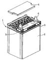
図1は、上蓋を外した状態での本発明の1実施形態に係る6セルモノブロック型の鉛蓄電池1を斜め上から見た斜視図である。2は電槽で、その内部は、電池の側辺のうち短辺に平行に配置された5個の隔壁(図示せず)によって6セルに分割されており、それぞれのセルに1組の正極板、負極板およびセパレータからなる極板群と希硫酸からなる電解液(図示せず)を収納している。図1の3は、電槽2の上に装着した中蓋で、4は、中蓋3の凹部に装着する上蓋である。電槽2、中蓋3、上蓋4は、何れもポリプロピレン製の成形体であり、電槽1の側壁上端(図示せず)と中蓋2の側壁下端(図示せず)および中蓋3の凹部に設けたの隔壁の上端と上蓋の隔壁の下端(図示せず)は熱融着されて、それぞれ気密に接合されている。なお5は、鉛合金製の正極端子、6は、鉛合金製の負極端子である。
Hereinafter, the details of the present invention will be described with reference to one embodiment, but the present invention is not limited thereto.
FIG. 1 is a perspective view of a 6-cell monoblock type lead-acid battery 1 according to an embodiment of the present invention with the top cover removed, as viewed obliquely from above. Reference numeral 2 denotes a battery case, the interior of which is divided into 6 cells by 5 partition walls (not shown) arranged in parallel to the short side of the side of the battery, and one set of positive electrodes for each cell. An electrode plate group consisting of a plate, a negative electrode plate and a separator and an electrolyte solution (not shown) consisting of dilute sulfuric acid are housed. In FIG. 1, 3 is an inner lid mounted on the battery case 2, and 4 is an upper lid mounted on a recess of the
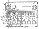
図2は、前記中蓋3を上から見た図である。中蓋3に設けた凹部31は、斜線を施した隔壁37′によって、電池の内側空間と外側空間に区画され、さらに電池の内側空間は、隔壁によってセル数と同じ6個に区画されている。
FIG. 2 is a view of the
一括排気を図るための構造には、排気室とは別に各セルに直結する排気用通路を設ける方法もあるが、集中排気室を電池の端部に配置し、排気ガスを各セルに対応する排気室を横断的に移行させて集中排気室に導き、集中排気室から電池の外へ排気する方が構造が簡単で排気経路のスペースが小さくて済む点から好ましい。この方式においては、隔壁によって形成された前記6個の区画を排気ガスが横断的に移行できるように連通させる必要がある。しかし、電池の使用中にセル間に電解液量の差が生じないようにするためには、各セルに対応する排気室内で結露した電解液が前記区画を横断的に移行することなく、対応するセル還流させる必要がある。そのためには、電解液が横断的に6個の区画間を横断的に移行するのを防ぐ排気室間障壁32を設けることが好ましい。
There is a method of providing exhaust passages that are directly connected to each cell separately from the exhaust chamber as a structure for collective exhaust, but a central exhaust chamber is arranged at the end of the battery, and exhaust gas corresponds to each cell. It is preferable that the exhaust chamber is moved transversely, led to the central exhaust chamber, and exhausted from the central exhaust chamber to the outside of the battery because the structure is simple and the space for the exhaust path is small. In this system, it is necessary to communicate the six compartments formed by the partition walls so that the exhaust gas can move transversely. However, in order to prevent a difference in the amount of electrolyte between cells during use of the battery, the electrolyte that has condensed in the exhaust chamber corresponding to each cell does not move across the compartment. The cell must be refluxed. For this purpose, it is preferable to provide an
後記のように上蓋の内面にも中蓋の隔壁に対応して、前記電池の内側空間を6個の室に区画する隔壁が設けられており、上蓋の隔壁には6個の室内を横断的にガスが移行できるように切り欠きが設ける、これに対して、中蓋の場合、室を6に分割する排気室間隔壁32には切り欠きを設けず、排気室間隔壁32をして電解液が6個の区画を横断的に移行するのを防ぐための障壁とすることが好ましい。
As will be described later, the inner surface of the upper lid is also provided with a partition that divides the inner space of the battery into six chambers corresponding to the partition of the inner lid. The partition of the upper lid crosses the six chambers. In contrast, in the case of the inner lid, the exhaust
前記区画のうち1個の区画を例に採って説明すると、35は、セル連通小室で該セル連通小室とセルとは、排気室で結露した電解液をセル内に還流する電解液還流口33、セルで発生したガスをセル連通室35に排出するガス排出口34を介してセルと連通している。セル連通小室35は、隔壁によって排気室37と区画され、隔壁に設けた切り欠き36を介して排気室37と連通しており該切り欠き36以外は隔壁によって排気室37と隔離されている。
An example of one of the compartments will be described. 35 is a cell communication chamber, and the cell communication chamber and the cell are an electrolyte
また、排気室37は、2つの隔離板41、42によって3つの小排気室(38、39、40)に区画されており、該隔壁にはそれぞれ1個の切り欠きを設け、隣合う排気小室同士は、前記隔離板41、42に設けた切り欠き43および44を介して連通している。後記の如く排気室の床面はセル連通小室35に近い側ほど低く、セル連通小室からの距離が大きくなるほど高くなるように、中蓋の短辺に沿って傾斜を持たせている。前記隔壁に設けた切り欠き(43、44)は、排気室の床面に設けた傾斜に平行な直線上に重ならないように配置して(図ではジグザグの位置にある)排気室を通過するガスの流路を長くしている。このことによって、排気室を通過する間に排気ガスに混入する電解液のミストや蒸気を効率良く結露させ、排気ガスから除去する。
The
45は、集中排気室で、隔壁32″によって排気室37(図では小排気室39)と区画されており、隔壁32″に設けた切り欠き46によって、3つの小排気室のうち、セル連通室から最も離れたところに位置する小排気室40に連通している。
45 is a centralized exhaust chamber, which is separated from an exhaust chamber 37 (
47は、注液室で、セルに開いた開口48を備え、周囲を隔壁47′によって排気室37(図では小排気室40)と区画されている。49は、中蓋3の凹部に後記上蓋4を装着するときの位置合わせ用ピンで後記上蓋に設けた筒状穴60と嵌合する。50は上蓋との接合を強固にするための接合用凸部である。
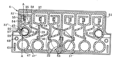
図3は、上蓋4を内面から見た図であり、斜線で示した前記上蓋の隔壁37′と接合する隔壁51と、上蓋に設けた位置合わせ用ピンに嵌合する筒状穴60を備える。電池内空間を6個に分割する排気室間隔壁32には、切り欠き52を設け排気ガスが排気室間で横断的な移行を可能にするための経路を形成している。また、該切り欠きに対向する位置に電解液の移行を抑制するための邪魔板53を配置している。さらにセル連通小室35のガス排気側と液還流側を区画する隔壁に切り欠き54を設け、セルから排出されたガスが排気室37へ移行するための経路を形成し、該切り欠きと対向する位置に邪魔板55を配置してガスに混じってセルから排出される電解液が排気室37へ移行するのを抑制している。
FIG. 3 is a view of the upper lid 4 as viewed from the inner surface, and includes a partition wall 51 to be joined to the
上蓋4を中蓋3の凹部の上に装着したときに、前記中蓋3の隔壁と上蓋4の隔壁はピッタリ重なる位置に配置されており、中蓋3の隔壁の上端と上蓋の隔壁の下端は、熱融着によって接合される。このように中蓋の隔壁と上蓋の隔壁を接合することによって、セル連通室と排気室、隣り合う排気小室同士、排気室と集中排気室は隔壁に設けた切り欠きを除いて隔離される。
また、図2および図3に示すように注液室47を取り囲む隔壁には切り欠きを設けず、上蓋の隔壁と中蓋の隔壁を接合することによって、注液室と排気室、注液室と電池外空間は気密に隔離する。
When the upper lid 4 is mounted on the concave portion of the
Further, as shown in FIGS. 2 and 3, the partition wall surrounding the
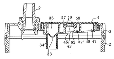
図4は、中蓋3の凹部に上蓋4を装着し、中蓋の凹部に設けた隔壁と上蓋の内面に設けた隔壁を接合させた状態を示す図であって、図2、図3のA−Aの線で示した部分の断面図である。中蓋3の凹部床壁62は、図4に示す如く、セル連通小室35に近い程低く、セル連通室35から遠い位置程高くなるように傾斜を持たせている。また、図2に示したように、排気室37を3個の排気小室38、39、40に分割する隔壁41、42を前記床壁62の傾斜に対して斜行させ、排気室間隔壁32と隔壁41、42のなす角度θを鋭角にし、かつ、隔壁41、42の切り欠き43、44を前記傾斜した床面の最も低い位置に配置しているので、電池が通常の状態(水平に置かれた状態)では、排気室37内で結露した電解液が排気室の床壁62に設けた傾斜に沿って液還流口側に移行し、滞留する虞がない。
FIG. 4 is a view showing a state in which the upper lid 4 is attached to the concave portion of the
セルの内部空間は、セル連通小室35と排気室37を連通させるために設けた隔壁36の切り欠きを除いて排気室37、さらには電池の外部空間と気密に封鎖されている。誤って電池を横転させた場合、電解液はセルからセル連通小室35に溢れ出て該セル連通室35を満たし、電解液面はセル連通室と排気室を連通させるために設けた隔壁の切り欠き36に至る。前記のようにセルの内部空間は該切り欠きを除いて電池の外部空間と気密に隔離されているので前記切り欠き36が電解液で塞がれている状態では空気がセル内に侵入することができず、前記切り欠き36に至った電解液面に大気圧が加わるので、セル連通小室35を下側になるように転倒させた場合、セル連通室35が上側になるように転倒させた場合いずれの場合にもセル内の電解液が排気室37に侵入するのをくい止めることができる。
The internal space of the cell is hermetically sealed from the
また、セル連通小室35が下側になるように転倒させた場合、排気室中に結露した電解液は排気室37を排気小室38、39、40に分割する隔壁に設けた切り欠き43、44を通ってセル連通室側35に移行するので、集中排気室に電解液が侵入するのを防ぐことができる。他方、セル連通室が上側になるように横転させた場合でも、図2、図3に示すように、排気室37に少なくとも2つの(本実施形態では2つ)隔壁41、42を配置し、各々の隔壁41、42の各々の隔壁に設けた切り欠き43、44を排気室37の床面の傾斜に対してジグザグに配置し、傾斜に平行な直線状に重ならないように配置しているので、電池を横転させた場合にも隔壁同士が上下方向に重なることがないので、セル連通小室35に近い排気小室38で結露した電解液が中間の小排気室39を素通りするのを防ぐことができる。また、排気室37を分割する隔壁を斜行させ、排気室間核兵器32と隔壁41、42のなす角度θを鋭角とすることにより、各排気小室が液溜空間を形成し、排気室内で結露した電解液が集中排気室へ移行するのを防ぐ。液溜空間を大きくするためには、隔壁41、42の切り欠き43、44に接する端部を図2、図3に示すように、セル連通室35の方向(排気室の床壁62が低い方向)に向かって屈曲させておくことが好ましい。
Further, when the cell communication
また、集中排気室45を上蓋4の短辺のほぼ中央に位置させ、集中排気室45がセル連通小室35から最も離れた排気小室40に連通し、セル連通小室35が下側になるように横転した状態においては、セル連通小室35が該排気小室40の上側に位置するようにすることによって排気室中で結露した電解液が集中排気室へ移行するのを防ぐことができるのでさらに好ましい。
Further, the
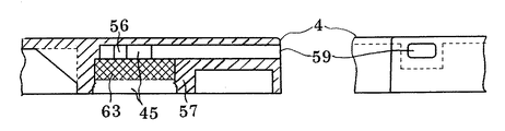
セルから排出された排気ガス中に混入した電解液のミストや蒸気は排気室37を通る間に結露し、その殆どが集中排気室45に至る迄に除去される。しかし、集中排気室45に至った排気ガスの中にも微量の電解が含まれる虞がある。該微量の電解液を除去するため、図4に示した如く、集中排気室を囲む上蓋4の隔壁57の内側にフィルターとしてポリプロピレン製やセラミックス製の多孔体63を嵌合させる。排気室内の圧力を高めることなくスムースに排気するためには、排気ガスはフィルターの厚み方向に通過することが好ましい。そのためには、フィルターと上蓋4の内壁面との間に空間を設ける必要がある。該フィルター63は集中排気室の筒状隔壁57に嵌合して係止しているので位置決めが難しいが、上蓋の内面に凸部56を設けることによって上蓋壁面とフィルターの間に間隔を設けることができる。該方法は簡便であり、且つ、一定の間隔を確保できる点で好ましい方法である。凸部56の形状や数量は特に限定されるものではないが、フィルターと上蓋の内壁面の間隔を平行にするには、上蓋壁面の集中排気室の内周部分に設けた環状の段差とするか、少なくとも3つの凸部56を等間隔に配置することが好ましい。該構成とすることによって、集中排気室に移行したガスは、フィルター内をその厚さ方向に移行し、集中排気室45の上蓋側空間に至り、排出路59を通って外部に排出される。
Mist and vapor of the electrolyte mixed in the exhaust gas discharged from the cell are condensed while passing through the
集中排気室45の床面には、集中排気室と小排気室を連通させるための隔壁に設けた切り欠き(図2の46)に近い程低く、切り欠きから遠くなるほど高くなるように傾斜を設けることが好ましい。また、ガスを電池外へ排出するための排出路59を切り欠きに46近い位置に設けることが好ましい。セルから排出されるガスによって排気室内の圧力が上昇した状態では、前記排気室内のガス圧によってガスが排気室から集中排気室45に移行する際、ガスの流れは集中排気室への入り口(切り欠き46に相当)から離れた奥の部分に集中し易い、従って、排気室で結露せずにガスに混入した微量の電解液のミストや蒸気の流れも集中排気室の奥の法に集中し易く、集中排気室の奥の部分で電解液が結露してフィルター63が目詰まりを起こす虞がある。集中排気室45の床の傾斜、集中排気室45から電池の外へ通じるガス排出路59の配置を前記の構成とすることによって排気ガスが均等にフィルターを通過するようにすることができる。
The floor of the
上蓋3と上蓋4の隔壁同士を熱融着によって接合する際、隔壁を加熱して軟化させた状態で上蓋と下蓋の隔壁同士を押圧するので隔壁が変形する虞がある。上蓋の集中排気室に装着したフィルター63は、上蓋4の内面に設けた集中排気室形成用の筒状隔壁57の中に嵌合して係止めしているので、上蓋4の隔壁57が変形して隔壁57の内寸に変化が起きるとフィルター63がはずれてしまう虞がある。このような不具合の発生を防ぐため、中蓋3の上面に設けたの隔壁32″に比べて、上蓋の隔壁57の機械的強度を高くして、両者を接合した時に上蓋に設けた隔壁に変形が生じ難くすることが好ましい。具体的には、図4に示した如く、中蓋の隔壁32″の厚さに比べて、上蓋の隔壁57の厚さを大きくすることが好ましい。両者の厚さの比率は特に限定されるものではないが、上蓋の隔壁57の厚さを中蓋の隔壁32″の厚さの1.5〜3倍に設定するのが好ましい。また、上蓋4の隔壁57の厚さを大きく設定し、該上蓋4の隔壁57の外周面に隔壁の高さ方向にリブ状突起58を設けることが更に好ましい。該リブ状突起の形状、寸法、数量は特に限定されるものではないが、少なくとも3箇所、隔壁の外周に沿って等間隔に配置されることが好ましい。
When joining the partition walls of the
図2に示したように、中蓋3には注液口48を設ける。注液口48を設けることによって、電槽上に中蓋3を装着した後に注液することが可能となり、注液後の電池組立工程において、電池に揺れや振動が加わっても電解液があふれ出る虞がなくハンドリングが容易となる。注液後中蓋3の凹部31に上蓋4を装着し中蓋3と上蓋4の隔壁を熱融着することによって気密に接合し、前記注液口48を囲む隔壁47′と上蓋4の壁面で排気室と気密に隔離した注液室47を形成することによって、電池を横転させた場合でも注液口48を通ってセル内の電解液が排気室37や、電池の外に漏出するのを防ぐことができる。
As shown in FIG. 2, a
図5は、集中排気室45のうち上蓋側の構造と排気路59を示す図である。集中排気室45の下方から流れてきたガスは、隔壁57に嵌着したフィルタ63を通過して、上蓋の内面に当接する空間に移行し、排気路59を経由して電池の外へ排出される。なお、上蓋の内面に設けた凸部56により前記上蓋の内面に一定の大きさを有する空間が確保される。
FIG. 5 is a view showing the structure of the upper lid side and the
前記のように、中蓋3の凹部31には上蓋との位置合わせ用のピン状凸部49を設け、上蓋の内面には、前記ピン状凸部49と嵌合させるための筒状穴60を設ける。中蓋の位置合わせ用部材を前記ピン状凸部49とすることによって、電槽2に中蓋3を装着し、電解液を注液したあと電槽外面を洗浄する工程で中蓋上面が洗浄水で濡れた場合でも嵌合部に水が残溜したり、異物を噛み込む虞がなくする利点がある。
以上、1実施形態により本発明の詳細を説明したが、本発明は前記1実施形態に限定されるされるものではない。
As described above, the
As mentioned above, although the details of the present invention were explained by one embodiment, the present invention is not limited to the first embodiment.
3 中蓋
4 上蓋
31 中蓋凹部
32 排気室間隔壁
32″ 中蓋に設けた集中排気室形成用隔壁
33 電解液還流口
34 ガス排出口
35 セル連通小室
37 排気室
38、39、40 排気小室
36、43、44、46 中蓋の隔壁に設けた切り欠き
45 集中排気室
47 注液室
49 ピン状凸部
52、54 上蓋の隔壁に設けた切り欠き
56 凸部
57 上蓋に設けた集中排気室形成用隔壁
60 筒状穴
63 フィルター
3 Middle lid 4
Claims (11)
9. The inner lid 3 is provided with an alignment pin 49 for overlapping with the upper lid 4, and the upper lid is provided with a cylindrical hole 60 for fitting with the alignment pin. Lead acid battery.
Priority Applications (1)
| Application Number | Priority Date | Filing Date | Title |
|---|---|---|---|
| JP2003400769A JP4715089B2 (en) | 2003-11-28 | 2003-11-28 | Lead acid battery |
Applications Claiming Priority (1)
| Application Number | Priority Date | Filing Date | Title |
|---|---|---|---|
| JP2003400769A JP4715089B2 (en) | 2003-11-28 | 2003-11-28 | Lead acid battery |
Publications (3)
| Publication Number | Publication Date |
|---|---|
| JP2005166318A true JP2005166318A (en) | 2005-06-23 |
| JP2005166318A5 JP2005166318A5 (en) | 2006-10-26 |
| JP4715089B2 JP4715089B2 (en) | 2011-07-06 |
Family
ID=34724907
Family Applications (1)
| Application Number | Title | Priority Date | Filing Date |
|---|---|---|---|
| JP2003400769A Expired - Fee Related JP4715089B2 (en) | 2003-11-28 | 2003-11-28 | Lead acid battery |
Country Status (1)
| Country | Link |
|---|---|
| JP (1) | JP4715089B2 (en) |
Cited By (19)
| Publication number | Priority date | Publication date | Assignee | Title |
|---|---|---|---|---|
| JP2005228649A (en) * | 2004-02-13 | 2005-08-25 | Furukawa Battery Co Ltd:The | Battery exhaust structure |
| JP2007335107A (en) * | 2006-06-12 | 2007-12-27 | Shin Kobe Electric Mach Co Ltd | Inspection method of lead acid battery |
| WO2008016144A1 (en) * | 2006-08-04 | 2008-02-07 | Gs Yuasa Corporation | Lead accumulator |
| WO2008016152A1 (en) * | 2006-08-04 | 2008-02-07 | Gs Yuasa Corporation | Lead acid battery |
| JP2008186690A (en) * | 2007-01-30 | 2008-08-14 | Gs Yuasa Corporation:Kk | Lead acid storage battery |
| JP2009129720A (en) * | 2007-11-23 | 2009-06-11 | Furukawa Battery Co Ltd:The | Method of molding exhaust nozzle for storage battery |
| JP2009238631A (en) * | 2008-03-27 | 2009-10-15 | Shin Kobe Electric Mach Co Ltd | Lead storage cell |
| JP2010021007A (en) * | 2008-07-10 | 2010-01-28 | Shin Kobe Electric Mach Co Ltd | Lead storage battery |
| WO2010140408A1 (en) * | 2009-06-02 | 2010-12-09 | 古河電池株式会社 | Secondary battery |
| JP2012515428A (en) * | 2009-01-13 | 2012-07-05 | ジョンソン コントロールズ テクノロジー カンパニー | Battery cover and exhaust cover for leak prevention |
| JP2014107262A (en) * | 2012-11-29 | 2014-06-09 | Global Battery Co Ltd | Cover for prevention of internal liquid leakage in storage battery |
| KR101490028B1 (en) | 2013-06-19 | 2015-02-06 | 세방전지(주) | Battery cover with sealed gas exhaust hole |
| CN109713174A (en) * | 2019-01-29 | 2019-05-03 | 梁甫富 | A kind of top cover for lead-acid accumulator of Semi-seal structure |
| WO2019097575A1 (en) * | 2017-11-14 | 2019-05-23 | 日立化成株式会社 | Lead storage battery |
| JP2019165012A (en) * | 2017-10-16 | 2019-09-26 | 日立化成株式会社 | Lead storage battery, idling stop car and micro hybrid car |
| US10665837B2 (en) | 2016-02-23 | 2020-05-26 | Gs Yuasa International Ltd. | Energy storage apparatus |
| CN111512470A (en) * | 2017-12-25 | 2020-08-07 | 株式会社杰士汤浅国际 | Lead storage battery |
| KR20210019158A (en) * | 2019-08-12 | 2021-02-22 | 주식회사 한국아트라스비엑스 | Venting structure to prevent electrolyte leakage of Flooded Battery |
| WO2023182139A1 (en) * | 2022-03-25 | 2023-09-28 | 株式会社Gsユアサ | Lead storage battery and method for manufacturing lead storage battery |
Families Citing this family (3)
| Publication number | Priority date | Publication date | Assignee | Title |
|---|---|---|---|---|
| JP6631015B2 (en) | 2015-02-27 | 2020-01-15 | 株式会社Gsユアサ | Lead storage battery |
| KR101818806B1 (en) | 2015-04-02 | 2018-01-15 | 주식회사 엘지화학 | Pouch type secondary battery and method for preparing the same |
| JP6576297B2 (en) | 2016-05-02 | 2019-09-18 | 日本ゴア株式会社 | Catalyst parts and vent filters, vent plugs and lead-acid batteries including the same |
Citations (7)
| Publication number | Priority date | Publication date | Assignee | Title |
|---|---|---|---|---|
| JPS52144747A (en) * | 1976-05-28 | 1977-12-02 | Furukawa Battery Co Ltd | Method of producing monoblock battery |
| JPS55109273U (en) * | 1979-01-27 | 1980-07-31 | ||
| JPH06176748A (en) * | 1992-12-08 | 1994-06-24 | Yuasa Corp | Storage battery |
| JPH0822815A (en) * | 1994-07-07 | 1996-01-23 | Yuasa Corp | Exhaust mechanism of storage battery |
| JP2001084981A (en) * | 1999-09-14 | 2001-03-30 | Yuasa Corp | Sealed lead-acid battery |
| JP2002540567A (en) * | 1999-03-22 | 2002-11-26 | グローリー ウィン インターナショナル グループ リミティド | Ventilation system for battery |
| JP2003109565A (en) * | 2001-09-25 | 2003-04-11 | Exide Industries Ltd | Exhaust electrolyte leakage resistance battery for motorcycles |
-
2003
- 2003-11-28 JP JP2003400769A patent/JP4715089B2/en not_active Expired - Fee Related
Patent Citations (7)
| Publication number | Priority date | Publication date | Assignee | Title |
|---|---|---|---|---|
| JPS52144747A (en) * | 1976-05-28 | 1977-12-02 | Furukawa Battery Co Ltd | Method of producing monoblock battery |
| JPS55109273U (en) * | 1979-01-27 | 1980-07-31 | ||
| JPH06176748A (en) * | 1992-12-08 | 1994-06-24 | Yuasa Corp | Storage battery |
| JPH0822815A (en) * | 1994-07-07 | 1996-01-23 | Yuasa Corp | Exhaust mechanism of storage battery |
| JP2002540567A (en) * | 1999-03-22 | 2002-11-26 | グローリー ウィン インターナショナル グループ リミティド | Ventilation system for battery |
| JP2001084981A (en) * | 1999-09-14 | 2001-03-30 | Yuasa Corp | Sealed lead-acid battery |
| JP2003109565A (en) * | 2001-09-25 | 2003-04-11 | Exide Industries Ltd | Exhaust electrolyte leakage resistance battery for motorcycles |
Cited By (30)
| Publication number | Priority date | Publication date | Assignee | Title |
|---|---|---|---|---|
| JP2005228649A (en) * | 2004-02-13 | 2005-08-25 | Furukawa Battery Co Ltd:The | Battery exhaust structure |
| JP2007335107A (en) * | 2006-06-12 | 2007-12-27 | Shin Kobe Electric Mach Co Ltd | Inspection method of lead acid battery |
| US8323811B2 (en) | 2006-08-04 | 2012-12-04 | Gs Yuasa International Ltd. | Lead acid storage battery |
| WO2008016144A1 (en) * | 2006-08-04 | 2008-02-07 | Gs Yuasa Corporation | Lead accumulator |
| WO2008016152A1 (en) * | 2006-08-04 | 2008-02-07 | Gs Yuasa Corporation | Lead acid battery |
| KR101404528B1 (en) * | 2006-08-04 | 2014-06-09 | 가부시키가이샤 지에스 유아사 | Lead accumulator |
| JP5266759B2 (en) * | 2006-08-04 | 2013-08-21 | 株式会社Gsユアサ | Lead acid battery |
| US8119270B2 (en) | 2006-08-04 | 2012-02-21 | Gs Yuasa International Ltd. | Lead acid battery with liquid sensor in lid |
| JP5115199B2 (en) * | 2006-08-04 | 2013-01-09 | 株式会社Gsユアサ | Lead acid battery |
| JP2008186690A (en) * | 2007-01-30 | 2008-08-14 | Gs Yuasa Corporation:Kk | Lead acid storage battery |
| JP2009129720A (en) * | 2007-11-23 | 2009-06-11 | Furukawa Battery Co Ltd:The | Method of molding exhaust nozzle for storage battery |
| JP2009238631A (en) * | 2008-03-27 | 2009-10-15 | Shin Kobe Electric Mach Co Ltd | Lead storage cell |
| JP2010021007A (en) * | 2008-07-10 | 2010-01-28 | Shin Kobe Electric Mach Co Ltd | Lead storage battery |
| JP2012515428A (en) * | 2009-01-13 | 2012-07-05 | ジョンソン コントロールズ テクノロジー カンパニー | Battery cover and exhaust cover for leak prevention |
| JP2010282743A (en) * | 2009-06-02 | 2010-12-16 | Furukawa Battery Co Ltd:The | Storage battery |
| WO2010140408A1 (en) * | 2009-06-02 | 2010-12-09 | 古河電池株式会社 | Secondary battery |
| JP2014107262A (en) * | 2012-11-29 | 2014-06-09 | Global Battery Co Ltd | Cover for prevention of internal liquid leakage in storage battery |
| KR101490028B1 (en) | 2013-06-19 | 2015-02-06 | 세방전지(주) | Battery cover with sealed gas exhaust hole |
| US10665837B2 (en) | 2016-02-23 | 2020-05-26 | Gs Yuasa International Ltd. | Energy storage apparatus |
| JP2019165012A (en) * | 2017-10-16 | 2019-09-26 | 日立化成株式会社 | Lead storage battery, idling stop car and micro hybrid car |
| WO2019097575A1 (en) * | 2017-11-14 | 2019-05-23 | 日立化成株式会社 | Lead storage battery |
| JPWO2019097575A1 (en) * | 2017-11-14 | 2020-11-19 | 日立化成株式会社 | Lead-acid battery |
| JP7093788B2 (en) | 2017-11-14 | 2022-06-30 | 昭和電工マテリアルズ株式会社 | Lead-acid battery |
| JP2022120197A (en) * | 2017-11-14 | 2022-08-17 | 昭和電工マテリアルズ株式会社 | lead acid battery |
| CN111512470A (en) * | 2017-12-25 | 2020-08-07 | 株式会社杰士汤浅国际 | Lead storage battery |
| CN111512470B (en) * | 2017-12-25 | 2024-08-27 | 株式会社杰士汤浅国际 | Lead acid battery |
| CN109713174A (en) * | 2019-01-29 | 2019-05-03 | 梁甫富 | A kind of top cover for lead-acid accumulator of Semi-seal structure |
| KR20210019158A (en) * | 2019-08-12 | 2021-02-22 | 주식회사 한국아트라스비엑스 | Venting structure to prevent electrolyte leakage of Flooded Battery |
| KR102225201B1 (en) * | 2019-08-12 | 2021-03-09 | 주식회사 한국아트라스비엑스 | Venting structure to prevent electrolyte leakage of Flooded Battery |
| WO2023182139A1 (en) * | 2022-03-25 | 2023-09-28 | 株式会社Gsユアサ | Lead storage battery and method for manufacturing lead storage battery |
Also Published As
| Publication number | Publication date |
|---|---|
| JP4715089B2 (en) | 2011-07-06 |
Similar Documents
| Publication | Publication Date | Title |
|---|---|---|
| JP4715089B2 (en) | Lead acid battery | |
| JP5115199B2 (en) | Lead acid battery | |
| CN103855333B (en) | The interior leakage of storage battery prevents lid | |
| AU2007318431B2 (en) | Battery case cover | |
| JP4138284B2 (en) | Exhaust electrolyte leakage resistance motorcycle battery | |
| CA1192947A (en) | Low silhouette venting system for electric storage battery | |
| JP5521390B2 (en) | Lead acid battery | |
| JP2015002166A (en) | Lead storage battery | |
| US4576879A (en) | Sealed lead acid battery | |
| WO2000057502A1 (en) | A venting system for a battery | |
| WO2006129340A1 (en) | Lead battery | |
| JP4715091B2 (en) | Lead acid battery | |
| JP5095992B2 (en) | Battery leakage prevention device for storage battery | |
| JP2009016063A (en) | Storage battery | |
| JP2008186690A (en) | Lead acid storage battery | |
| JP4246600B2 (en) | Battery exhaust structure | |
| JP2013004436A (en) | Lead battery | |
| JP4715090B2 (en) | Lead acid battery | |
| EP0107469B1 (en) | Low silhouette venting system for electric storage battery | |
| JP5184000B2 (en) | Storage battery exhaust structure | |
| JP4698153B2 (en) | Battery exhaust structure | |
| JP7210925B2 (en) | lead acid battery | |
| HK1120929B (en) | Lead battery | |
| CN116845442A (en) | Battery cover and battery | |
| CN202678474U (en) | Lead storage battery and motor vehicle provided with the same |
Legal Events
| Date | Code | Title | Description |
|---|---|---|---|
| A711 | Notification of change in applicant |
Free format text: JAPANESE INTERMEDIATE CODE: A712 Effective date: 20051219 |
|
| A521 | Request for written amendment filed |
Free format text: JAPANESE INTERMEDIATE CODE: A523 Effective date: 20060125 |
|
| A521 | Request for written amendment filed |
Free format text: JAPANESE INTERMEDIATE CODE: A523 Effective date: 20060912 |
|
| A621 | Written request for application examination |
Free format text: JAPANESE INTERMEDIATE CODE: A621 Effective date: 20061019 |
|
| A977 | Report on retrieval |
Free format text: JAPANESE INTERMEDIATE CODE: A971007 Effective date: 20090911 |
|
| A711 | Notification of change in applicant |
Free format text: JAPANESE INTERMEDIATE CODE: A712 Effective date: 20100507 |
|
| A131 | Notification of reasons for refusal |
Free format text: JAPANESE INTERMEDIATE CODE: A131 Effective date: 20100713 |
|
| A521 | Request for written amendment filed |
Free format text: JAPANESE INTERMEDIATE CODE: A523 Effective date: 20100913 |
|
| A131 | Notification of reasons for refusal |
Free format text: JAPANESE INTERMEDIATE CODE: A131 Effective date: 20101109 |
|
| A521 | Request for written amendment filed |
Free format text: JAPANESE INTERMEDIATE CODE: A523 Effective date: 20101229 |
|
| TRDD | Decision of grant or rejection written | ||
| A01 | Written decision to grant a patent or to grant a registration (utility model) |
Free format text: JAPANESE INTERMEDIATE CODE: A01 Effective date: 20110301 |
|
| A61 | First payment of annual fees (during grant procedure) |
Free format text: JAPANESE INTERMEDIATE CODE: A61 Effective date: 20110314 |
|
| R150 | Certificate of patent or registration of utility model |
Ref document number: 4715089 Country of ref document: JP Free format text: JAPANESE INTERMEDIATE CODE: R150 Free format text: JAPANESE INTERMEDIATE CODE: R150 |
|
| FPAY | Renewal fee payment (event date is renewal date of database) |
Free format text: PAYMENT UNTIL: 20140408 Year of fee payment: 3 |
|
| LAPS | Cancellation because of no payment of annual fees |