JP2005166300A - Female terminal for large current and female terminal for large current with shell - Google Patents
Female terminal for large current and female terminal for large current with shell Download PDFInfo
- Publication number
- JP2005166300A JP2005166300A JP2003400092A JP2003400092A JP2005166300A JP 2005166300 A JP2005166300 A JP 2005166300A JP 2003400092 A JP2003400092 A JP 2003400092A JP 2003400092 A JP2003400092 A JP 2003400092A JP 2005166300 A JP2005166300 A JP 2005166300A
- Authority
- JP
- Japan
- Prior art keywords
- blade
- contact
- elastic piece
- female terminal
- receiving space
- Prior art date
- Legal status (The legal status is an assumption and is not a legal conclusion. Google has not performed a legal analysis and makes no representation as to the accuracy of the status listed.)
- Pending
Links
Images


Classifications
-
- H—ELECTRICITY
- H01—ELECTRIC ELEMENTS
- H01R—ELECTRICALLY-CONDUCTIVE CONNECTIONS; STRUCTURAL ASSOCIATIONS OF A PLURALITY OF MUTUALLY-INSULATED ELECTRICAL CONNECTING ELEMENTS; COUPLING DEVICES; CURRENT COLLECTORS
- H01R13/00—Details of coupling devices of the kinds covered by groups H01R12/70 or H01R24/00 - H01R33/00
- H01R13/02—Contact members
- H01R13/10—Sockets for co-operation with pins or blades
- H01R13/11—Resilient sockets
- H01R13/113—Resilient sockets co-operating with pins or blades having a rectangular transverse section
-
- H—ELECTRICITY
- H01—ELECTRIC ELEMENTS
- H01R—ELECTRICALLY-CONDUCTIVE CONNECTIONS; STRUCTURAL ASSOCIATIONS OF A PLURALITY OF MUTUALLY-INSULATED ELECTRICAL CONNECTING ELEMENTS; COUPLING DEVICES; CURRENT COLLECTORS
- H01R13/00—Details of coupling devices of the kinds covered by groups H01R12/70 or H01R24/00 - H01R33/00
- H01R13/02—Contact members
- H01R13/15—Pins, blades or sockets having separate spring member for producing or increasing contact pressure
- H01R13/187—Pins, blades or sockets having separate spring member for producing or increasing contact pressure with spring member in the socket
Landscapes
- Coupling Device And Connection With Printed Circuit (AREA)
Abstract
Description
本発明は雌端子の分野に属し、ほぼ板状のブレードを備えたブレード形の雄端子のブレードが挿入、抜去される大電流用雌端子に関する。 The present invention belongs to the field of female terminals, and relates to a female terminal for large current in which a blade-shaped male terminal blade having a substantially plate-like blade is inserted and removed.
特許文献1は、雄端子の端子ピンを嵌入する筒状接触部を備えた雌端子において、上記筒状接触部の端子ピン挿入端側の外周に環状の薄肉部を設け、薄肉部には適宜間隔をおいて筒状接触部の内面に突出する複数の突起を設けたことを特徴とする大電流用雌端子を開示している。 In Patent Document 1, in a female terminal having a cylindrical contact portion into which a terminal pin of a male terminal is inserted, an annular thin portion is provided on the outer periphery of the cylindrical contact portion on the terminal pin insertion end side, and the thin portion is appropriately provided. There is disclosed a female terminal for large current, which is provided with a plurality of protrusions protruding from the inner surface of a cylindrical contact portion at intervals.
特許文献2は、棒状の雄端子が挿入される挿入孔を有するとともに、挿入孔の開口側に大径の収容部を連続的に形成した雌端子と、多数の弓なり状の板ばね片の一端側のみを連結させて、全体を上記雄端子の外径及び上記雌端子の挿入孔の内径に対応する略円筒状とするとともに、上記板ばね片の連結させた一端側に、板ばね片と直交する方向に突出し、上記雌端子の収容部奥壁に当接する固定リブを形成した接触ばね部材と、上記雄端子が挿通される挿通孔を有し、上記雌端子の収容部に取り付けられ、上記接触ばね部材の固定リブを挟持して、上記接触ばね部材を上記雌端子の挿入孔内に固定するキャップとを備えた大電流充電用端子を開示している。
特許文献1の大電流用雌端子は、安定な接触抵抗が得られるが、突起が雄端子のピンと点接触するので、突起とピンとの接触面積が小さく、接触抵抗を充分低くすることができない。 The high current female terminal of Patent Document 1 can provide stable contact resistance, but since the protrusion makes point contact with the pin of the male terminal, the contact area between the protrusion and the pin is small, and the contact resistance cannot be sufficiently reduced.
特許文献2の大電流充電用端子は、接触ばね部材の板ばね片が雄端子の外径及び雌端子の挿入孔の内径に対応する略円筒状となるよう配置されるので、各板ばね片と雄端子とは点接触となって接触面積が小さくなることから、接触抵抗を充分低くすることができない。 Since the leaf spring piece of the contact spring member is arranged so as to have a substantially cylindrical shape corresponding to the outer diameter of the male terminal and the inner diameter of the insertion hole of the female terminal, the large current charging terminal of Patent Document 2 is provided. Since the contact area between the male terminal and the male terminal becomes point contact and the contact area becomes small, the contact resistance cannot be made sufficiently low.
本発明は、このような点に着目してなされたもので、その目的とするところは、ブレード形の雄端子のブレードが挿入、抜去される雌端子を対象とし、ブレードとの接触箇所を複数とし、各接触箇所の接触面積を大きくし、接触圧力を高くすることで雄端子との接触抵抗を確実に低減し、両端子間で大電流を低損失で安定的に流すことができ、また本体部におけるブレードの位置決めを正確に行うことができる大電流用雌端子を提供することにある。 The present invention has been made paying attention to such points, and the object of the present invention is to target a female terminal into which a blade of a blade-shaped male terminal is inserted and removed, and to provide a plurality of contact points with the blade. By increasing the contact area of each contact point and increasing the contact pressure, the contact resistance with the male terminal can be reliably reduced, and a large current can be stably passed between the two terminals with low loss. An object of the present invention is to provide a female terminal for large current capable of accurately positioning a blade in a main body.
上記目的を達成するため、請求項1は、互いに直交する奥行き方向、幅方向及び高さ方向をとったときに、高さよりも大きな幅をもって奥行き方向の手前に延びるほぼ板状のブレードを備えたブレード形の雄端子のブレードが挿入、抜去される大電流用雌端子である。この大電流用雌端子は、奥行き方向に延びる筒状に設けられ、奥側からブレードを受け入れる受入空間が内部に設けられた本体部と、本体部の奥行き方向の手前に設けられ、導体を接続する接続部とを備え、本体部は、受入空間に対して高さ方向の少なくとも一方側において高さ方向に弾性変形するように設けられ且つ内面に所定幅にわたって接触部が設けられた第1弾性片と、受入空間に対して幅方向の少なくとも一方側において幅方向に弾性変形するように設けられ且つ内面に所定高さにわたって接触部が設けられた第2弾性片とを備え、ブレードが受入空間に挿入されたときに、ブレードの高さ方向の一方の端面に第1弾性片の接触部が接触圧力をもって接触し、ブレードの幅方向の一方の端面に第2弾性片の接触部が接触圧力をもって接触するように構成している。 In order to achieve the above object, claim 1 comprises a substantially plate-like blade extending in front of the depth direction with a width larger than the height when taking a depth direction, a width direction, and a height direction orthogonal to each other. This is a female terminal for large current into which a blade-type male terminal blade is inserted and removed. This female terminal for large current is provided in a cylindrical shape extending in the depth direction, and is provided with a main body part in which a receiving space for receiving a blade from the back side is provided inside, and in front of the main body part in the depth direction, and connects a conductor. A first elastic member provided with a contact portion over a predetermined width on the inner surface, and the main body portion is provided so as to elastically deform in the height direction on at least one side in the height direction with respect to the receiving space. A blade and the receiving space provided with a second elastic piece that is provided so as to be elastically deformed in the width direction on at least one side in the width direction with respect to the receiving space, and in which a contact portion is provided on the inner surface over a predetermined height. When the blade is inserted into the blade, the contact portion of the first elastic piece comes into contact with one end surface in the height direction of the blade with contact pressure, and the contact portion of the second elastic piece comes into contact with one end surface in the width direction of the blade. With It is configured to contact.
ブレードが受入空間に挿入されると、ブレードの高さ方向の一方の端面に第1弾性片の接触部が接触圧力をもって接触し、ブレードの高さ方向の他方の端面に本体部における受入空間に面する部分が接触圧力をもって接触する。またブレードの幅方向の一方の端面に第2弾性片の接触部が接触圧力をもって接触し、ブレードの幅方向の他方の端面に本体部における受入空間に面する部分が接触圧力をもって接触する。その場合、大電流用雌端子はブレードに対して第1弾性片の接触部及び第2弾性片の接触部を含む複数箇所で接触する。しかも、これらの接触部は点接触ではなく線接触ないしは面接触によりブレードに接触するので、大きな接触面積が得られる。さらに、弾性片の弾性復原力により接触部では高い接触圧力が得られる。そのため、雌端子と雄端子との接触抵抗が確実に低減され、両端子間で大電流が低損失で安定的に流れることになる。また、第1弾性片と、本体部における受入空間に面する部分とによりブレードが狭持され、第2弾性片と、本体部における受入空間に面する部分とによりブレードが狭持されるので、本体部におけるブレードの位置決めが正確に行われる。 When the blade is inserted into the receiving space, the contact portion of the first elastic piece comes into contact with one end surface in the height direction of the blade with contact pressure, and the other end surface in the height direction of the blade enters the receiving space in the main body portion. The facing part contacts with contact pressure. Further, the contact portion of the second elastic piece comes into contact with one end surface in the width direction of the blade with contact pressure, and the portion facing the receiving space in the main body portion comes into contact with the other end surface in the width direction of the blade with contact pressure. In that case, the female terminal for large current contacts the blade at a plurality of locations including the contact portion of the first elastic piece and the contact portion of the second elastic piece. In addition, since these contact portions contact the blade not by point contact but by line contact or surface contact, a large contact area can be obtained. Further, a high contact pressure is obtained at the contact portion due to the elastic restoring force of the elastic piece. Therefore, the contact resistance between the female terminal and the male terminal is reliably reduced, and a large current flows stably between the two terminals with low loss. In addition, the blade is sandwiched between the first elastic piece and the portion facing the receiving space in the main body, and the blade is sandwiched between the second elastic piece and the portion facing the receiving space in the main body. The blade is accurately positioned in the main body.
請求項2の大電流用雌端子は、請求項1の大電流用雌端子において、本体部における受入空間に対して高さ方向の他方側には、内面に所定幅にわたって接触部が設けられた横壁が設けられ、ブレードが受入空間に挿入されたときに、ブレードの高さ方向の他方の端面に横壁の接触部が接触圧力をもって接触するように構成している。 The female terminal for large current according to claim 2 is the female terminal for large current according to claim 1, wherein a contact portion is provided on the inner surface over a predetermined width on the other side in the height direction with respect to the receiving space in the main body. A lateral wall is provided, and when the blade is inserted into the receiving space, the contact portion of the lateral wall contacts the other end surface in the height direction of the blade with contact pressure.
このようにすれば、ブレードが受入空間に挿入されると、ブレードの高さ方向の一方の端面に第1弾性片の接触部が接触圧力をもって接触し、ブレードの高さ方向の他方の端面に本体部の横壁の接触部が接触圧力をもって接触する。 In this way, when the blade is inserted into the receiving space, the contact portion of the first elastic piece comes into contact with one end surface in the height direction of the blade with contact pressure, and the other end surface in the height direction of the blade. The contact part of the horizontal wall of the main body part comes into contact with contact pressure.
請求項3の大電流用雌端子は、請求項1の大電流用雌端子において、本体部における受入空間に対して高さ方向の他方側には、高さ方向に弾性変形するように設けられ且つ内面に所定幅にわたって接触部が設けられた別の第1弾性片が設けられ、ブレードが受入空間に挿入されたときに、ブレードの高さ方向の他方の端面に、この第1弾性片の接触部が接触圧力をもって接触するように構成している。 The female terminal for high current according to claim 3 is the female terminal for large current according to claim 1, provided on the other side in the height direction with respect to the receiving space in the main body so as to be elastically deformed in the height direction. Further, another first elastic piece having a contact portion provided on the inner surface over a predetermined width is provided, and when the blade is inserted into the receiving space, the first elastic piece is placed on the other end surface in the height direction of the blade. The contact portion is configured to contact with a contact pressure.
このようにすれば、ブレードが受入空間に挿入されると、ブレードの高さ方向の両端面に第1弾性片の接触部がそれぞれ接触圧力をもって接触する。 In this way, when the blade is inserted into the receiving space, the contact portions of the first elastic piece come into contact with both end faces in the height direction of the blade with contact pressure.
請求項4の大電流用雌端子は、請求項1ないし請求項3のうちいずれか1項の大電流用雌端子において、本体部における受入空間に対して幅方向の他方側には、内面に所定高さにわたって接触部が設けられた縦壁が設けられ、ブレードが受入空間に挿入されたときに、ブレードの幅方向の他方の端面に縦壁の接触部が接触圧力をもって接触するように構成している。 The female terminal for large current according to claim 4 is the female terminal for large current according to any one of claims 1 to 3, wherein the other side in the width direction with respect to the receiving space in the main body is on the inner surface. A vertical wall provided with a contact portion over a predetermined height is provided, and when the blade is inserted into the receiving space, the contact portion of the vertical wall contacts the other end surface in the width direction of the blade with contact pressure. doing.
このようにすれば、ブレードが受入空間に挿入されると、ブレードの幅方向の一方の端面に第2弾性片の接触部が接触圧力をもって接触し、ブレードの幅方向の他方の端面に本体部の縦壁の接触部が接触圧力をもって接触する。 In this way, when the blade is inserted into the receiving space, the contact portion of the second elastic piece contacts with one end surface in the width direction of the blade with contact pressure, and the main body portion contacts with the other end surface in the width direction of the blade. The contact part of the vertical wall contacts with contact pressure.
請求項5の大電流用雌端子は、請求項1ないし請求項3のうちいずれか1項の大電流用雌端子において、本体部における受入空間に対して幅方向の他方側には、幅方向に弾性変形するように設けられ且つ内面に所定高さにわたって接触部が設けられた別の第2弾性片が設けられ、ブレードが受入空間に挿入されたときに、ブレードの幅方向の他方の端面に、この第2弾性片の接触部が接触圧力をもって接触するように構成している。 The female terminal for large current according to claim 5 is the female terminal for large current according to any one of claims 1 to 3, wherein the widthwise direction is on the other side in the width direction with respect to the receiving space in the main body. When the blade is inserted into the receiving space, the other end surface in the width direction of the blade is provided with another second elastic piece which is provided so as to be elastically deformed and has an inner surface provided with a contact portion over a predetermined height. In addition, the contact portion of the second elastic piece is configured to contact with a contact pressure.
このようにすれば、ブレードが受入空間に挿入されると、ブレードの幅方向の両端面に第2弾性片の接触部がそれぞれ接触圧力をもって接触する。 If it does in this way, when a braid | blade is inserted in receiving space, the contact part of a 2nd elastic piece will contact with the both ends of the width direction of a braid | blade with a contact pressure, respectively.
請求項6の大電流用雌端子は、請求項1ないし請求項5のうちいずれか1項の大電流用雌端子において、本体部が奥行き方向の奥側の端にある奥端部と手前側の端にある手前端部とに分割され、奥端部を構成する奥端部構成壁と手前端部を構成する手前端部構成壁とが第1弾性片、第2弾性片又はこれら双方の弾性片によって連結されており、奥端部構成壁と手前端部構成壁とを連結する弾性片は、中途部が受入空間に向かって接近するように屈曲しており、この屈曲部に接触部が設けられている。 The female terminal for large current according to claim 6 is the female terminal for large current according to any one of claims 1 to 5, wherein the main body portion is located at the far end and the near side at the far end in the depth direction. And the front end portion constituting the back end portion and the front end constituting wall constituting the front end portion of the first elastic piece, the second elastic piece, or both of them. The elastic piece, which is connected by the elastic piece and connects the rear end constituent wall and the front end constituent wall, is bent so that the middle part approaches the receiving space, and the contact part is in contact with the bent part. Is provided.
このようにすれば、弾性片が両端で本体部に支持されているので、例えば一端のみが本体部に支持された片持ちの弾性片に較べると、弾性片の奥行き方向の長さがほぼ同じであれば、接触部で得られる接触圧力が高くなる。また、奥端部構成壁と、第1弾性片、第2弾性片又はこれら双方の弾性片と、手前端部構成壁とが切れ目無く連続するので、ブレードの挿入、抜去が引っ掛かりなくスムーズに行われる。さらに、第1弾性片、第2弾性片又はこれら双方の弾性片の外側には本体部の構成壁がないので、大電流用雌端子の高さ、幅又は両方を小さくすることができる。 In this way, since the elastic piece is supported by the main body at both ends, for example, the length of the elastic piece in the depth direction is substantially the same as compared to a cantilever elastic piece that is supported by the main body only at one end. If so, the contact pressure obtained at the contact portion is increased. In addition, since the rear end constituent wall, the first elastic piece, the second elastic piece or both elastic pieces, and the front end constituent wall are continuous without interruption, the insertion and removal of the blade can be performed smoothly without being caught. Is called. Further, since there is no constituent wall of the main body outside the first elastic piece, the second elastic piece, or both elastic pieces, the height, width, or both of the large current female terminals can be reduced.
請求項7の大電流用雌端子は、請求項1ないし請求項6のうちいずれか1項の大電流用雌端子において、第1弾性片が、幅方向に複数並べて設けられている。 The female terminal for large current according to claim 7 is the female terminal for large current according to any one of claims 1 to 6, wherein a plurality of first elastic pieces are arranged in the width direction.
このようにすれば、ブレードの高さ方向の端面が幅方向に若干傾斜していても、この傾斜に追従して複数の第1弾性片の接触部がそれぞれブレードの端面に良好に接触する。 In this way, even if the end surface in the height direction of the blade is slightly inclined in the width direction, the contact portions of the plurality of first elastic pieces are in good contact with the end surfaces of the blade following the inclination.
請求項8のシェル付き大電流用雌端子は、請求項1ないし請求項7のうちいずれか1項の大電流用雌端子と、奥行き方向に延びて大電流用雌端子の本体部に外側から嵌合する筒状のシェルとを備えている。 The female terminal for large current with a shell according to claim 8 is provided with the female terminal for large current according to any one of claims 1 to 7 and the main body of the female terminal for large current from the outside, extending in the depth direction. And a cylindrical shell to be fitted.
このシェル付き大電流用雌端子からは、請求項1ないし請求項7で得られた作用と同様の作用が得られる。このシェル付き大電流用雌端子はブレードに対して大きな接触面積で接触すると共に高い接触圧力で接触する。その場合、シェルによって大電流用雌端子の変形が規制されるので、接触片が予定どおりの機能を発揮し、接触部がブレードに対して高い接触圧力でもって接触する。また、弾性片が過大に変形したときにシェルがこれを規制して弾性片の塑性変形、破損が防止される。さらに、シェルによって内部の弾性片が外力から保護される。また、シェルに例えば外側へ立ち上がる突片を設け、ハウジングに、シェル付き大電流用雌端子を収容する収容室と突片をガイドするガイド溝を設ければ、シェル付き大電流用雌端子をハウジングに挿入するときに高さ方向や奥行き方向に向きがあっていない状態でハウジングに挿入してしまう逆差しや本来相手側部材ではないハウジングに挿入してしまう誤挿入などを防止する機能が発揮される。 From the female terminal for large current with shell, the same action as that obtained in claims 1 to 7 can be obtained. The female terminal for large current with a shell contacts the blade with a large contact area and contacts with a high contact pressure. In that case, since the deformation of the female terminal for large current is restricted by the shell, the contact piece exhibits a function as planned, and the contact portion contacts the blade with a high contact pressure. Moreover, when an elastic piece deform | transforms excessively, a shell controls this and the elastic deformation of a elastic piece and a failure | damage are prevented. Further, the inner elastic piece is protected from external force by the shell. For example, if the shell is provided with a protruding piece that rises to the outside, for example, and the housing is provided with a housing chamber for storing the female terminal for large current with a shell and a guide groove for guiding the protruding piece, the female terminal for large current with the shell is A function to prevent reverse insertion that inserts into the housing when it is not oriented in the height direction or depth direction when inserted into the housing, or erroneous insertion that inserts into a housing that is not originally a mating member is demonstrated. The
請求項1の大電流用雌端子は、ブレードとの接触箇所を複数とし、各接触箇所の接触面積を大きくし、接触圧力を高くできるので、雄端子との接触抵抗を確実に低減し、両端子間で大電流を低損失で安定的に流すことができると共に、本体部におけるブレードの位置決めを正確に行うことができる。 The female terminal for high current according to claim 1 has a plurality of contact points with the blade, can increase the contact area of each contact point, and can increase the contact pressure, thereby reliably reducing the contact resistance with the male terminal. A large current can be stably passed between the children with low loss, and the blade can be accurately positioned in the main body.
請求項2のようにすれば、受入空間に対して高さ方向の一方側にのみ第1弾性片が設けられているので、構造が比較的簡単になる。 According to the second aspect, since the first elastic piece is provided only on one side in the height direction with respect to the receiving space, the structure becomes relatively simple.
請求項3のようにすれば、受入空間に対して高さ方向の両側に第1弾性片が設けられているので、第1弾性片の弾性変形量を比較的小さく抑えることができる。 According to the third aspect, since the first elastic pieces are provided on both sides in the height direction with respect to the receiving space, the amount of elastic deformation of the first elastic pieces can be kept relatively small.
請求項4のようにすれば、受入空間に対して幅方向の一方側にのみ第2弾性片が設けられているので、構造が比較的簡単になる。 According to the fourth aspect, since the second elastic piece is provided only on one side in the width direction with respect to the receiving space, the structure becomes relatively simple.
請求項5のようにすれば、受入空間に対して幅方向の両側に第2弾性片が設けられているので、第2弾性片の弾性変形量を比較的小さく抑えることができる。 According to the fifth aspect, since the second elastic pieces are provided on both sides in the width direction with respect to the receiving space, the amount of elastic deformation of the second elastic pieces can be kept relatively small.
請求項6のようにすれば、奥端部構成壁と手前端部構成壁とが第1弾性片、第2弾性片又はこれら双方の弾性片によって連結されるので、弾性片を両端で本体部に支持することで接触部で得られる接触圧力が高くなり、ブレードの挿入、抜去を引っ掛かりなくスムーズに行うことができ、大電流用雌端子の高さ、幅又は両方を小さくすることができる。 According to the sixth aspect of the present invention, the rear end constituent wall and the front end constituent wall are connected by the first elastic piece, the second elastic piece or both elastic pieces, so that the elastic piece is connected to the main body at both ends. The contact pressure obtained at the contact portion is increased by supporting the blade, the blade can be smoothly inserted and removed without being caught, and the height, width, or both of the female terminal for large current can be reduced.
請求項7のようにすれば、ブレードの高さ方向の端面が幅方向に若干傾斜していても、この傾斜に追従して複数の第1弾性片の接触部がそれぞれブレードの端面に良好に接触するので、接触状態が安定する。 According to the seventh aspect, even if the end surface in the height direction of the blade is slightly inclined in the width direction, the contact portions of the plurality of first elastic pieces follow each of the end surfaces of the blade favorably following the inclination. The contact state is stabilized because of contact.
請求項8のシェル付き大電流用雌端子からは、請求項1ないし請求項7で得られた効果と同様の効果が得られる。さらに、シェルによって大電流用雌端子の変形が規制されるので、接触片が予定どおりの機能を発揮し、接触部がブレードに対して高い接触圧力でもって接触する。また、弾性片が過大に変形したときにシェルがこれを規制して弾性片の塑性変形、破損が防止される。さらに、シェルによって内部の弾性片が外力から保護される。また、逆差し防止、誤挿入防止の機能を発揮させることができ、この機能が要望されたときに大電流用雌端子自体は設計変更せず、これに嵌合するシェルを設計又は選択することで要望に応えることができる。 The effect similar to that obtained in claims 1 to 7 can be obtained from the female terminal for large current with shell of claim 8. Further, since the deformation of the female terminal for large current is regulated by the shell, the contact piece exhibits a function as planned, and the contact portion contacts the blade with a high contact pressure. Moreover, when an elastic piece deform | transforms excessively, a shell controls this and the elastic deformation of a elastic piece and a failure | damage are prevented. Further, the inner elastic piece is protected from external force by the shell. In addition, the function of preventing reverse insertion and prevention of incorrect insertion can be exhibited, and when this function is desired, the design of the shell to be fitted to this should be designed or selected without changing the design of the female terminal for high current. Can meet your needs.
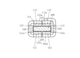
以下、本発明の実施の形態を説明する。図1ないし図12は本発明の第1の実施形態である大電流用雌端子100を示す。互いに直交する奥行き方向、幅方向及び高さ方向を想定し、これらの方向付けを利用して説明する。この実施形態の場合、図3で説明すれば、図の左右方向が奥行き方向であり、図の左方が奥行き方向の奥、右方が奥行き方向の手前である。また、図の紙面に垂直な方向が高さ方向であり、図の上下方向が幅方向である。
Embodiments of the present invention will be described below. 1 to 12 show a
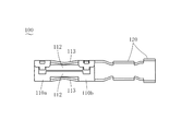
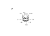
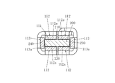
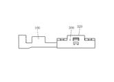
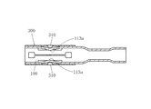
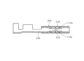
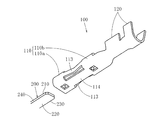
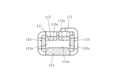
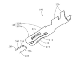
図1に示すように、この大電流用雌端子100には、ブレード形の雄端子(本体は図示を省略)のブレード200が挿入、抜去される。このブレード200は高さよりも大きな幅をもって奥行き方向の奥から手前に向かって延びるほぼ板状に形成されている。大電流用雌端子100は導電性の材料で形成されている。大電流用雌端子100は、奥行き方向に延びる筒状に設けられ、奥側からブレード200を受け入れる受入空間111が内部に設けられた本体部110と、本体部110の奥行き方向の手前に設けられ、導体を接続する接続部120とを備えている。この実施形態の場合、導体は電線であり、接続部120は電線の被覆をかしめて圧着接続するインシュレーションバレルと電線の芯線をかしめて圧着接続するワイヤバレルとを備えるが、接続部の他の例としては電線を圧入すると電線の絶縁被覆を破って導体との接続を行う圧接スロットを備えたものがある。また、導体は電線に限定されるものではなく、例えばFFC(フレキシブル・フラット・ケーブル)の導体であってもよく、そのときは接続部として例えばピアシングを行う突起部を備えるものがある。
As shown in FIG. 1, a
本体部110には、受入空間111に対して高さ方向の少なくとも一方側に、第1弾性片112が高さ方向に弾性変形するように設けられている。第1弾性片112の内面には所定幅にわたって接触部112aが設けられている。内面とは、本体部110にブレード200を挿入したときにブレード200に接触する側の面である。所定幅は、第1弾性片112の幅と同一の寸法か、それよりも短い寸法で設定される。第1弾性片112は、幅方向に延びる短辺と奥行き方向に延びる長辺とで高さ方向からみてほぼ矩形状に形成され且つ高さ方向に厚みをもつ板状に形成されているが、これによって本発明の第1弾性片の形状が限定されるものではない。接触部112aの奥行き方向の長さは適宜に定められる。また、本体部110には、受入空間111に対して幅方向の少なくとも一方側に、第2弾性片113が幅方向に弾性変形するように設けられている。第2弾性片113の内面には所定高さにわたって接触部113aが設けられている。内面とは、本体部110にブレード200を挿入したときにブレード200に接触する側の面である。所定高さは、第2弾性片113の高さと同一の寸法か、それよりも短い寸法で設定される。第2弾性片113は、高さ方向に延びる短辺と奥行き方向に延びる長辺とで幅方向からみてほぼ矩形状に形成され且つ幅方向に厚みをもつ板状に形成されているが、これによって本発明の第2弾性片の形状が限定されるものではない。接触部113aの奥行き方向の長さは適宜に定められる。そして、ブレード200が受入空間111に挿入されたときに、ブレード200の高さ方向の一方の端面210に第1弾性片112の接触部112aが接触圧力をもって接触し、ブレード200の幅方向の一方の端面230に第2弾性片113の接触部113aが接触圧力をもって接触するように構成している。
In the
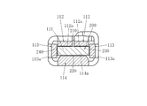
本体部110における受入空間111に対して高さ方向の他方側には、別の第1弾性片112が高さ方向に弾性変形するように設けられている。第1弾性片112の内面には所定幅にわたって接触部112aが設けられている。そして、ブレード200が受入空間111に挿入されたときに、ブレード200の高さ方向の他方の端面220に、この第1弾性片112の接触部112aが接触圧力をもって接触するように構成している。内面及び所定幅の意義は先に説明したとおりである。
On the other side in the height direction with respect to the receiving
本体部110における受入空間111に対して幅方向の他方側には、別の第2弾性片113が幅方向に弾性変形するように設けられている。第2弾性片113の内面には所定高さにわたって接触部113aが設けられている。そして、ブレード200が受入空間111に挿入されたときに、ブレード200の幅方向の他方の端面240に、この第2弾性片113の接触部113aが接触圧力をもって接触するように構成している。内面及び所定高さの意義は先に説明したとおりである。
On the other side in the width direction with respect to the receiving
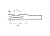
本体部110は奥行き方向の奥側の端にある奥端部110aと手前側の端にある手前端部110bとに分割されている。奥端部110aを構成する奥端部構成壁と手前端部110bを構成する手前端部構成壁とが第1弾性片112、第2弾性片113又はこれら双方の弾性片112、113によって連結されている。奥端部構成壁と手前端部構成壁とを連結する弾性片112、113は、中途部が受入空間111に向かって接近するように屈曲しており、この屈曲部に接触部112a、113aが設けられている。
The
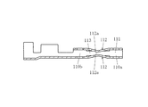
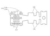
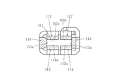
第1弾性片112は、幅方向に複数並べて設けられている。大電流用雌端子100は、図12に示すように所定形状に形成された1枚の原板を折り曲げて形成される。しかし、本発明の大電流用雌端子は複数の部材で構成してもよく、この実施形態によって構造、製造方法が限定されるものではない。
A plurality of first
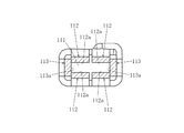
次に、第1の実施形態の大電流用雌端子100の作用及び効果を説明する。図11に示すように、ブレード200が受入空間111に挿入されると、ブレード200の高さ方向の一方の端面210に第1弾性片112の接触部112aが接触圧力をもって接触し、ブレード200の高さ方向の他方の端面220に本体部110における受入空間111に面する部分が接触圧力をもって接触する。またブレード200の幅方向の一方の端面230に第2弾性片113の接触部113aが接触圧力をもって接触し、ブレード200の幅方向の他方の端面240に本体部110における受入空間111に面する部分が接触圧力をもって接触する。その場合、大電流用雌端子100はブレード200に対して第1弾性片112の接触部112a及び第2弾性片113の接触部113aを含む複数箇所で接触する。しかも、これらの接触部112a、113aは点接触ではなく線接触ないしは面接触によりブレード200に接触するので、大きな接触面積が得られる。さらに、弾性片112、113の弾性復原力により接触部112a、113aでは高い接触圧力が得られる。そのため、大電流用雌端子100と雄端子との接触抵抗が確実に低減され、両端子間で大電流が低損失で安定的に流れることになる。また、第1弾性片112と、本体部110における受入空間111に面する部分とによりブレード200が狭持され、第2弾性片113と、本体部110における受入空間111に面する部分とによりブレード200が狭持されるので、本体部110におけるブレード200の位置決めが正確に行われる。
Next, the operation and effect of the large current
本発明は、本体部に、受入空間に対して高さ方向の一方の側にのみ、高さ方向に弾性変形するように設けられ且つ内面に所定幅にわたって接触部が設けられた第1弾性片を設けた実施形態を含む。これに対して、第1実施形態の場合、さらに、本体部110における受入空間111に対して高さ方向の他方側には、高さ方向に弾性変形するように設けられ且つ内面に所定幅にわたって接触部112aが設けられた別の第1弾性片112が設けられ、ブレード200が受入空間111に挿入されたときに、ブレード200の高さ方向の他方の端面220に、この第1弾性片112の接触部112aが接触圧力をもって接触するように構成している。このようにすれば、ブレード200が受入空間111に挿入されると、ブレード200の高さ方向の両端面210、220に第1弾性片112の接触部112aがそれぞれ接触圧力をもって接触する。よって第1弾性片112の弾性変形量を比較的小さく抑えることができる。
The present invention provides a first elastic piece which is provided on the main body portion so as to be elastically deformed in the height direction only on one side in the height direction with respect to the receiving space and is provided with a contact portion on the inner surface over a predetermined width. Including the embodiment. On the other hand, in the case of the first embodiment, the other side in the height direction with respect to the receiving
本発明は、本体部に、受入空間に対して幅方向の一方の側にのみ、幅方向に弾性変形するように設けられ且つ内面に所定高さにわたって接触部が設けられた第2弾性片を設けた実施形態を含む。これに対して、第1実施形態の場合、さらに、本体部110における受入空間111に対して幅方向の他方側には、幅方向に弾性変形するように設けられ且つ内面に所定高さにわたって接触部113aが設けられた別の第2弾性片113が設けられ、ブレード200が受入空間111に挿入されたときに、ブレード200の幅方向の他方の端面240に、この第2弾性片113の接触部113aが接触圧力をもって接触するように構成している。このようにすれば、ブレード200が受入空間111に挿入されると、ブレード200の幅方向の両端面230、240に第2弾性片113の接触部113aがそれぞれ接触圧力をもって接触する。よって第2弾性片113の弾性変形量を比較的小さく抑えることができる。
According to the present invention, the second elastic piece is provided on the main body portion so as to be elastically deformed in the width direction only on one side in the width direction with respect to the receiving space, and the contact portion is provided on the inner surface over a predetermined height. Includes provided embodiments. On the other hand, in the case of the first embodiment, the other side in the width direction with respect to the receiving
本発明は、本体部を分割せずに一体的に設け、この本体部の内部に第1弾性片、第2弾性片又はこれら双方の弾性片を設けた実施形態を含む。これに対して、第1実施形態の場合、本体部110が奥行き方向の奥側の端にある奥端部110aと手前側の端にある手前端部110bとに分割され、奥端部110aを構成する奥端部構成壁と手前端部110bを構成する手前端部構成壁とが第1弾性片112、第2弾性片113又はこれら双方の弾性片によって連結されており、奥端部構成壁と手前端部構成壁とを連結する弾性片112、113は、中途部が受入空間111に向かって接近するように屈曲しており、この屈曲部に接触部112a、113aが設けられている。このようにすれば、第1弾性片112、第2弾性片113が両端で本体部110に支持されているので、例えば一端のみが本体部に支持された片持ちの弾性片に較べると、弾性片の奥行き方向の長さがほぼ同じであれば、接触部112a、113aで得られる接触圧力が高くなる。また、奥端部構成壁と、第1弾性片112、第2弾性片113又はこれら双方の弾性片と、手前端部構成壁とが切れ目無く連続するので、ブレード200の挿入、抜去が引っ掛かりなくスムーズに行われる。さらに、第1弾性片112、第2弾性片113又はこれら双方の弾性片の外側には本体部110の構成壁がないので、大電流用雌端子100の高さ、幅又は両方を小さくすることができる。
The present invention includes an embodiment in which the main body portion is provided integrally without being divided, and the first elastic piece, the second elastic piece, or both elastic pieces are provided inside the main body portion. On the other hand, in the case of the first embodiment, the
本発明は、受入空間に対して高さ方向の一方側に単一の第1弾性片を設けた実施形態、受入空間に対して高さ方向の両側にそれぞれ単一の第1弾性片を設けた実施形態を含む。これに対して、第1実施形態の場合、第1弾性片112が、幅方向に複数並べて設けられている。このようにすれば、ブレード200の高さ方向の端面210、220が幅方向に若干傾斜していても、この傾斜に追従して複数の第1弾性片112の接触部112aがそれぞれブレード200の端面210、220に良好に接触し、接触状態が安定する。
The present invention is an embodiment in which a single first elastic piece is provided on one side in the height direction with respect to the receiving space, and a single first elastic piece is provided on each side in the height direction with respect to the receiving space. Embodiments. On the other hand, in the case of the first embodiment, a plurality of first
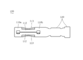
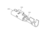
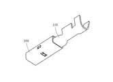
次に、本発明の大電流用雌端子の他の実施形態を説明する。第1実施形態と同様の構成については同一符号を付して説明を省略し、異なる構成について説明することにする。図13ないし図17は、第2の実施形態としてシェル付き大電流用雌端子を示す。このシェル付き大電流用雌端子は、第1実施形態の大電流用雌端子100と、奥行き方向に延びて本体部110に外側から嵌合する筒状のシェル300とを備えている。このシェル300には、第1弾性片112の屈曲部及び第2弾性片113の屈曲部に対応する部位からこれらの屈曲部に向かって立ち上がる突起310が設けられており、この突起310が第1弾性片112及び第2弾性片113の過変形を防止している。
Next, another embodiment of the female terminal for large current of the present invention will be described. The same components as those in the first embodiment are denoted by the same reference numerals, description thereof is omitted, and different components are described. 13 to 17 show a female terminal for large current with a shell as a second embodiment. The female terminal for large current with shell includes the female terminal for large current 100 according to the first embodiment and a
このシェル付き大電流用雌端子からは、第1実施形態で得られた作用及び効果と同様の作用及び効果が得られる。このシェル付き大電流用雌端子はブレード200に対して大きな接触面積で接触すると共に高い接触圧力で接触する。その場合、シェル300によって大電流用雌端子100の変形が規制されるので、第1接触片112、第2接触片113が予定どおりの機能を発揮し、接触部112a、113aがブレード200に対して高い接触圧力でもって接触する。また、第1接触片112、第2接触片113が過大に変形したときにシェル300がこれを規制して第1接触片112、第2接触片113の塑性変形、破損が防止される。さらに、シェルによって内部の第1弾性片112、第2弾性片113が外力から保護される。また、図13及び図15に示すように、シェル300に例えば外側へ立ち上がる突片320を設け、ハウジング(図示を省略)に、シェル付き大電流用雌端子を収容する収容室と突片320をガイドするガイド溝を設ければ、シェル付き大電流用雌端子をハウジングに挿入するときに高さ方向や奥行き方向に向きがあっていない状態でハウジングに挿入してしまう逆差しや本来相手側部材ではないハウジングに挿入してしまう誤挿入などを防止する機能が発揮される。その場合、この機能が要望されたときに大電流用雌端子自体は設計変更せず、これに嵌合するシェル300を設計又は選択することで要望に応えることができる。
From the female terminal for large current with shell, the same actions and effects as those obtained in the first embodiment can be obtained. The female terminal for large current with a shell contacts the
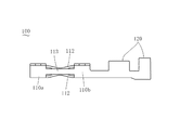
図18ないし図20は、第3の実施形態である大電流用雌端子100を示す。第1実施形態の大電流用雌端子100の場合、本体部110における受入空間111に対して高さ方向の他方側に、高さ方向に弾性変形するように設けられ且つ内面に所定幅にわたって接触部112aが設けられた別の第1弾性片112を設けた。これに対して、第3実施形態の場合、本体部110における受入空間111に対して高さ方向の他方側には、内面に所定幅にわたって接触部114aが設けられた横壁114が設けられ、ブレード200が受入空間111に挿入されたときに、ブレード200の高さ方向の他方の端面220に横壁114の接触部114aが接触圧力をもって接触するように構成している。内面とは、本体部110にブレード200を挿入したときにブレード200に接触する側の面である。接触部114aは平板状の横壁114の内面の一部の領域で形成してもよいが、接触圧力を上げて接点を確定するためには、接触部114aは受入空間111に向かって突出させて設けることが好ましい。接触部114aの奥行き方向の長さは適宜に定められる。
18 to 20 show a
第3実施形態の大電流用雌端子100の場合、図20に示すように、ブレード200が受入空間111に挿入されると、ブレード200の高さ方向の一方の端面210に第1弾性片112の接触部112aが接触圧力をもって接触し、ブレード200の高さ方向の他方の端面220に本体部110の横壁114の接触部114aが接触圧力をもって接触する。この大電流用雌端子100からは、第1実施形態で得られた作用及び効果と同様の作用及び効果が得られると共に、受入空間111に対して高さ方向の一方側にのみ第1弾性片112が設けられているので、構造が比較的簡単になる。
In the case of the large current
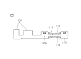
図21ないし図23は、第4の実施形態である大電流用雌端子100を示す。この第4実施形態の場合、本体部110における受入空間111に対して幅方向の他方側には、内面に所定高さにわたって接触部115aが設けられた縦壁115が設けられ、ブレード200が受入空間111に挿入されたときに、ブレード200の幅方向の他方の端面240に縦壁115の接触部115aが接触圧力をもって接触するように構成している。内面とは、本体部110にブレード200を挿入したときにブレード200に接触する側の面である。接触部115aは平板状の縦壁115の内面の一部の領域で形成してもよいが、接触圧力を上げて接点を確定するためには、接触部115aは受入空間111に向かって突出させて設けることが好ましい。接触部115aの奥行き方向の長さは適宜に定められる。
FIGS. 21 to 23 show a
第4実施形態の大電流用雌端子100の場合、図23に示すように、ブレード200が受入空間111に挿入されると、ブレード200の幅方向の一方の端面230に第2弾性片113の接触部113aが接触圧力をもって接触し、ブレード200の幅方向の他方の端面240に本体部110の縦壁115の接触部115aが接触圧力をもって接触する。この大電流用雌端子100からは、第1実施形態で得られた作用及び効果と同様の作用及び効果が得られると共に、受入空間111に対して幅方向の一方側にのみ第2弾性片113が設けられているので、構造が比較的簡単になる。
In the case of the large current
以上の実施形態では、本体部110と第1弾性片112及び第2弾性片113とを奥行き方向にずらして設けたが、本体部のなかに第1弾性片、第2弾性片又は双方の弾性片を設けてもよい。上記実施形態では第1弾性片112及び第2弾性片113を、その奥側の端と手前側の端とで本体部110に連結したが、弾性片の一方の端を本体部に連結し、他方の端を自由端にしてもよい。また、例えば弾性片にU字状の折り曲げ部を設けるなど、雌端子の弾性片として公知の構造を採用してもよい。上記実施形態では弾性片112、113の中途部に屈曲部を設け、この屈曲部に接触部112a、113aを設けたが、1つの弾性片に奥行き方向に沿って複数の屈曲部を設け、これらの屈曲部にそれぞれ接触部を設けてもよい。所定幅、所定高さは、第1弾性片、第2弾性片、横壁、縦壁における接触部の長さとしてそれぞれ任意に定められる寸法であり、文言の一致をもって寸法の一致を意味するものではない。
In the above embodiment, the
100 大電流用雌端子
110 本体部
110a 奥端部
110b 手前端部
111 受入空間
112 第1弾性片
112a 接触部
113 第2弾性片
113a 接触部
114 横壁
114a 接触部
115 縦壁
115a 接触部
120 接続部
200 ブレード
210 高さ方向の一方の端面
220 高さ方向の他方の端面
230 幅方向の一方の端面
240 幅方向の他方の端面
300 シェル
DESCRIPTION OF
Claims (8)
奥行き方向に延びる筒状に設けられ、奥側からブレードを受け入れる受入空間が内部に設けられた本体部と、
本体部の奥行き方向の手前に設けられ、導体を接続する接続部とを備え、
本体部は、受入空間に対して高さ方向の少なくとも一方側において高さ方向に弾性変形するように設けられ且つ内面に所定幅にわたって接触部が設けられた第1弾性片と、
受入空間に対して幅方向の少なくとも一方側において幅方向に弾性変形するように設けられ且つ内面に所定高さにわたって接触部が設けられた第2弾性片とを備え、
ブレードが受入空間に挿入されたときに、ブレードの高さ方向の一方の端面に第1弾性片の接触部が接触圧力をもって接触し、ブレードの幅方向の一方の端面に第2弾性片の接触部が接触圧力をもって接触するように構成した大電流用雌端子。 When taking the depth direction, width direction, and height direction orthogonal to each other, a blade-shaped male terminal blade having a substantially plate-like blade extending in front of the depth direction with a width larger than the height is inserted and removed. A female terminal for large current,
A main body provided in a cylindrical shape extending in the depth direction and having a receiving space for receiving a blade from the back side;
Provided in front of the main body in the depth direction, and provided with a connecting portion for connecting a conductor,
The main body portion is provided so as to be elastically deformed in the height direction on at least one side in the height direction with respect to the receiving space, and a first elastic piece having a contact portion provided on the inner surface over a predetermined width;
A second elastic piece provided so as to be elastically deformed in the width direction on at least one side in the width direction with respect to the receiving space, and provided with a contact portion on the inner surface over a predetermined height;
When the blade is inserted into the receiving space, the contact portion of the first elastic piece contacts one end surface in the height direction of the blade with contact pressure, and the second elastic piece contacts one end surface in the width direction of the blade. A female terminal for large current configured such that the portion contacts with contact pressure.
奥端部を構成する奥端部構成壁と手前端部を構成する手前端部構成壁とが第1弾性片、第2弾性片又はこれら双方の弾性片によって連結されており、
奥端部構成壁と手前端部構成壁とを連結する弾性片は、中途部が受入空間に向かって接近するように屈曲しており、この屈曲部に接触部が設けられている請求項1ないし請求項5のうちいずれか1項の大電流用雌端子。 The main body is divided into a back end at the back end in the depth direction and a front end at the front end,
The back end constituting wall constituting the back end and the front end constituting wall constituting the front end are connected by the first elastic piece, the second elastic piece or both elastic pieces,
The elastic piece that connects the rear end constituting wall and the front end constituting wall is bent so that the midway portion approaches the receiving space, and a contact portion is provided at the bent portion. The female terminal for large currents according to any one of claims 5 to 5.
Priority Applications (2)
| Application Number | Priority Date | Filing Date | Title |
|---|---|---|---|
| JP2003400092A JP2005166300A (en) | 2003-11-28 | 2003-11-28 | Female terminal for large current and female terminal for large current with shell |
| US10/996,498 US7048597B2 (en) | 2003-11-28 | 2004-11-23 | Female terminal for heavy current and female terminal for heavy current with shell |
Applications Claiming Priority (1)
| Application Number | Priority Date | Filing Date | Title |
|---|---|---|---|
| JP2003400092A JP2005166300A (en) | 2003-11-28 | 2003-11-28 | Female terminal for large current and female terminal for large current with shell |
Publications (1)
| Publication Number | Publication Date |
|---|---|
| JP2005166300A true JP2005166300A (en) | 2005-06-23 |
Family
ID=34616644
Family Applications (1)
| Application Number | Title | Priority Date | Filing Date |
|---|---|---|---|
| JP2003400092A Pending JP2005166300A (en) | 2003-11-28 | 2003-11-28 | Female terminal for large current and female terminal for large current with shell |
Country Status (2)
| Country | Link |
|---|---|
| US (1) | US7048597B2 (en) |
| JP (1) | JP2005166300A (en) |
Cited By (9)
| Publication number | Priority date | Publication date | Assignee | Title |
|---|---|---|---|---|
| EP2485334A1 (en) | 2011-02-04 | 2012-08-08 | Sumitomo Wiring Systems, Ltd. | Multi-contact terminal fitting |
| JP2013004452A (en) * | 2011-06-21 | 2013-01-07 | Yazaki Corp | Female terminal |
| JP2013004453A (en) * | 2011-06-21 | 2013-01-07 | Yazaki Corp | Female terminal |
| JP2013045566A (en) * | 2011-08-23 | 2013-03-04 | Tyco Electronics Japan Kk | Female terminal |
| WO2014174912A1 (en) * | 2013-04-23 | 2014-10-30 | 日本航空電子工業株式会社 | Connector and illuminating device |
| KR101550924B1 (en) | 2009-05-19 | 2015-09-07 | 타이코에이엠피 주식회사 | connector for the low-profile fuse |
| KR20160037682A (en) * | 2014-09-29 | 2016-04-06 | 크루셜텍 (주) | Wire-terminel assembly for camera |
| WO2021166738A1 (en) * | 2020-02-21 | 2021-08-26 | 住友電装株式会社 | Connector module, communication cable with connector, and connector assembly |
| WO2021166740A1 (en) * | 2020-02-21 | 2021-08-26 | 住友電装株式会社 | Connector assembly |
Families Citing this family (20)
| Publication number | Priority date | Publication date | Assignee | Title |
|---|---|---|---|---|
| CH704749B1 (en) * | 2007-09-05 | 2012-10-15 | Preci Dip Sa | contact clip. |
| US7559779B1 (en) | 2008-05-14 | 2009-07-14 | Cinch Connectors, Inc. | Electrical connector |
| JP5854276B2 (en) * | 2012-05-18 | 2016-02-09 | 株式会社オートネットワーク技術研究所 | Female terminal |
| JP5853908B2 (en) * | 2012-08-29 | 2016-02-09 | 日立金属株式会社 | Connector and wire harness |
| US8721376B1 (en) | 2012-11-01 | 2014-05-13 | Avx Corporation | Single element wire to board connector |
| US20140120786A1 (en) | 2012-11-01 | 2014-05-01 | Avx Corporation | Single element wire to board connector |
| US9548553B2 (en) * | 2013-03-15 | 2017-01-17 | Lear Corporation | Terminal with front end protection |
| CN104466481B (en) * | 2013-09-12 | 2018-08-10 | 大众汽车有限公司 | Contact accessory for plug-in connector |
| US9391386B2 (en) | 2014-10-06 | 2016-07-12 | Avx Corporation | Caged poke home contact |
| DE102015201635A1 (en) * | 2015-01-30 | 2016-08-04 | Te Connectivity Germany Gmbh | Contact element and assembly arrangement with selbigem |
| CN110313110B (en) * | 2017-03-01 | 2021-02-05 | 莫列斯有限公司 | Electrical Terminals and Connector Assemblies |
| US10320096B2 (en) | 2017-06-01 | 2019-06-11 | Avx Corporation | Flexing poke home contact |
| TWI685159B (en) * | 2017-09-26 | 2020-02-11 | 瀚荃股份有限公司 | Socket connector and socket terminal thereof |
| CN108963510A (en) * | 2018-07-05 | 2018-12-07 | 欧品电子(昆山)有限公司 | High speed connector component, socket connector and its female terminal |
| JP6784959B2 (en) * | 2019-04-17 | 2020-11-18 | 住友電装株式会社 | Communication cable with connector and connector assembly |
| JP7165306B2 (en) * | 2019-06-11 | 2022-11-04 | 株式会社オートネットワーク技術研究所 | Terminals and wires with terminals |
| CN112350092B (en) * | 2019-08-08 | 2023-07-18 | 上海莫仕连接器有限公司 | Connector and terminal |
| EP3783744B1 (en) | 2019-08-23 | 2026-03-25 | Yazaki Europe Ltd. | Electric connection arrangement |
| CN111293478B (en) * | 2020-03-20 | 2021-10-26 | 河南天海电器有限公司 | Finger touch prevention structure |
| CN114883833A (en) * | 2022-06-21 | 2022-08-09 | 奇瑞商用车(安徽)有限公司 | Connecting terminal |
Family Cites Families (7)
| Publication number | Priority date | Publication date | Assignee | Title |
|---|---|---|---|---|
| DE9211819U1 (en) * | 1992-07-07 | 1993-11-04 | Grote & Hartmann | Electrical contact element |
| JP3115805B2 (en) | 1995-09-14 | 2000-12-11 | 矢崎総業株式会社 | Terminal fittings and method of manufacturing terminal fittings |
| JPH09134751A (en) | 1995-11-08 | 1997-05-20 | Yazaki Corp | Box-shaped joint structure of terminal fittings |
| JP3412738B2 (en) | 1996-10-11 | 2003-06-03 | 矢崎総業株式会社 | Method of forming female terminal for large current |
| JPH10294143A (en) | 1997-04-18 | 1998-11-04 | Yazaki Corp | Terminal fitting |
| JP3424796B2 (en) | 1997-08-11 | 2003-07-07 | 矢崎総業株式会社 | Large current charging terminal |
| DE19841232C2 (en) * | 1998-09-09 | 2001-02-15 | Framatome Connectors Int | Socket contact for electrical plugs |
-
2003
- 2003-11-28 JP JP2003400092A patent/JP2005166300A/en active Pending
-
2004
- 2004-11-23 US US10/996,498 patent/US7048597B2/en not_active Expired - Lifetime
Cited By (18)
| Publication number | Priority date | Publication date | Assignee | Title |
|---|---|---|---|---|
| KR101550924B1 (en) | 2009-05-19 | 2015-09-07 | 타이코에이엠피 주식회사 | connector for the low-profile fuse |
| US8616925B2 (en) | 2011-02-04 | 2013-12-31 | Sumitomo Wiring Systems, Ltd. | Multi-contact terminal fitting |
| EP2485334A1 (en) | 2011-02-04 | 2012-08-08 | Sumitomo Wiring Systems, Ltd. | Multi-contact terminal fitting |
| US9142901B2 (en) | 2011-06-21 | 2015-09-22 | Yazaki Corporation | Female terminal |
| US9017116B2 (en) | 2011-06-21 | 2015-04-28 | Yazaki Corporation | Female terminal |
| JP2013004453A (en) * | 2011-06-21 | 2013-01-07 | Yazaki Corp | Female terminal |
| JP2013004452A (en) * | 2011-06-21 | 2013-01-07 | Yazaki Corp | Female terminal |
| JP2013045566A (en) * | 2011-08-23 | 2013-03-04 | Tyco Electronics Japan Kk | Female terminal |
| WO2014174912A1 (en) * | 2013-04-23 | 2014-10-30 | 日本航空電子工業株式会社 | Connector and illuminating device |
| US9761967B2 (en) | 2013-04-23 | 2017-09-12 | Japan Aviation Electronics Industry, Limited | Connector and illuminating device |
| KR101687207B1 (en) * | 2014-09-29 | 2016-12-28 | 크루셜텍 (주) | Wire-terminel assembly for camera |
| KR20160037682A (en) * | 2014-09-29 | 2016-04-06 | 크루셜텍 (주) | Wire-terminel assembly for camera |
| WO2021166738A1 (en) * | 2020-02-21 | 2021-08-26 | 住友電装株式会社 | Connector module, communication cable with connector, and connector assembly |
| WO2021166740A1 (en) * | 2020-02-21 | 2021-08-26 | 住友電装株式会社 | Connector assembly |
| JP2021136068A (en) * | 2020-02-21 | 2021-09-13 | 住友電装株式会社 | Connector assembly |
| JP2021136067A (en) * | 2020-02-21 | 2021-09-13 | 住友電装株式会社 | Connector module, communication cable with connector, and connector assembly |
| CN115066809A (en) * | 2020-02-21 | 2022-09-16 | 住友电装株式会社 | Connector assembly |
| CN115104228A (en) * | 2020-02-21 | 2022-09-23 | 住友电装株式会社 | Connector Modules, Communication Cables with Connectors, and Connector Assemblies |
Also Published As
| Publication number | Publication date |
|---|---|
| US20050118891A1 (en) | 2005-06-02 |
| US7048597B2 (en) | 2006-05-23 |
Similar Documents
| Publication | Publication Date | Title |
|---|---|---|
| JP2005166300A (en) | Female terminal for large current and female terminal for large current with shell | |
| JP4299184B2 (en) | Board connection board terminal | |
| US7717755B2 (en) | Electrical connector with improved contacts | |
| KR101700058B1 (en) | Female terminal | |
| CN103748745B (en) | Female terminal and use the adapter of described female terminal | |
| US7422465B2 (en) | Electrical connector having flexible mating portion | |
| JP2007165194A (en) | connector | |
| JP2007165195A (en) | Connector | |
| JP7039435B2 (en) | Connector assembly | |
| CN101359788A (en) | Connector and Connector Terminal Structure | |
| JP2007134301A (en) | Vertical mating female terminal and housing to which this is mounted | |
| JP2012216344A (en) | Connector | |
| JP2008004342A (en) | Female terminal fitting | |
| US20210044055A1 (en) | Connector and terminal | |
| JP3143222U (en) | Connector with improved dual beam contact | |
| US6116956A (en) | Electrical connector for a power supply | |
| KR100988789B1 (en) | terminal | |
| JP4314106B2 (en) | Female terminal | |
| US6206732B1 (en) | Electrical connector | |
| JP2014143023A (en) | Female type terminal and connector | |
| KR101001886B1 (en) | terminal | |
| EP1804344A2 (en) | Electrical connector having flexible mating portion | |
| KR101520927B1 (en) | Terminal | |
| KR20100011331A (en) | Tab terminal and terminal assembly having this | |
| CN119401149A (en) | A crimping terminal, a crimping terminal assembly and an electrical connector |
Legal Events
| Date | Code | Title | Description |
|---|---|---|---|
| A621 | Written request for application examination |
Free format text: JAPANESE INTERMEDIATE CODE: A621 Effective date: 20050826 |
|
| A977 | Report on retrieval |
Free format text: JAPANESE INTERMEDIATE CODE: A971007 Effective date: 20070605 |
|
| A131 | Notification of reasons for refusal |
Free format text: JAPANESE INTERMEDIATE CODE: A131 Effective date: 20080325 |
|
| A02 | Decision of refusal |
Free format text: JAPANESE INTERMEDIATE CODE: A02 Effective date: 20080722 |