EP3783744A1 - Electric connection arrangement - Google Patents
Electric connection arrangement Download PDFInfo
- Publication number
- EP3783744A1 EP3783744A1 EP19193311.8A EP19193311A EP3783744A1 EP 3783744 A1 EP3783744 A1 EP 3783744A1 EP 19193311 A EP19193311 A EP 19193311A EP 3783744 A1 EP3783744 A1 EP 3783744A1
- Authority
- EP
- European Patent Office
- Prior art keywords
- lamellae
- connection arrangement
- blade
- receiving space
- electric connection
- Prior art date
- Legal status (The legal status is an assumption and is not a legal conclusion. Google has not performed a legal analysis and makes no representation as to the accuracy of the status listed.)
- Pending
Links
Images

Classifications
-
- H—ELECTRICITY
- H01—ELECTRIC ELEMENTS
- H01R—ELECTRICALLY-CONDUCTIVE CONNECTIONS; STRUCTURAL ASSOCIATIONS OF A PLURALITY OF MUTUALLY-INSULATED ELECTRICAL CONNECTING ELEMENTS; COUPLING DEVICES; CURRENT COLLECTORS
- H01R13/00—Details of coupling devices of the kinds covered by groups H01R12/70 or H01R24/00 - H01R33/00
- H01R13/02—Contact members
- H01R13/10—Sockets for co-operation with pins or blades
- H01R13/11—Resilient sockets
- H01R13/113—Resilient sockets co-operating with pins or blades having a rectangular transverse section
-
- H—ELECTRICITY
- H01—ELECTRIC ELEMENTS
- H01R—ELECTRICALLY-CONDUCTIVE CONNECTIONS; STRUCTURAL ASSOCIATIONS OF A PLURALITY OF MUTUALLY-INSULATED ELECTRICAL CONNECTING ELEMENTS; COUPLING DEVICES; CURRENT COLLECTORS
- H01R13/00—Details of coupling devices of the kinds covered by groups H01R12/70 or H01R24/00 - H01R33/00
- H01R13/02—Contact members
- H01R13/04—Pins or blades for co-operation with sockets
-
- H—ELECTRICITY
- H01—ELECTRIC ELEMENTS
- H01R—ELECTRICALLY-CONDUCTIVE CONNECTIONS; STRUCTURAL ASSOCIATIONS OF A PLURALITY OF MUTUALLY-INSULATED ELECTRICAL CONNECTING ELEMENTS; COUPLING DEVICES; CURRENT COLLECTORS
- H01R13/00—Details of coupling devices of the kinds covered by groups H01R12/70 or H01R24/00 - H01R33/00
- H01R13/02—Contact members
- H01R13/22—Contacts for co-operating by abutting
- H01R13/24—Contacts for co-operating by abutting resilient; resiliently-mounted
- H01R13/2464—Contacts for co-operating by abutting resilient; resiliently-mounted characterized by the contact point
- H01R13/2492—Contacts for co-operating by abutting resilient; resiliently-mounted characterized by the contact point multiple contact points
-
- H—ELECTRICITY
- H01—ELECTRIC ELEMENTS
- H01R—ELECTRICALLY-CONDUCTIVE CONNECTIONS; STRUCTURAL ASSOCIATIONS OF A PLURALITY OF MUTUALLY-INSULATED ELECTRICAL CONNECTING ELEMENTS; COUPLING DEVICES; CURRENT COLLECTORS
- H01R24/00—Two-part coupling devices, or either of their cooperating parts, characterised by their overall structure
- H01R24/20—Coupling parts carrying sockets, clips or analogous contacts and secured only to wire or cable
-
- H—ELECTRICITY
- H01—ELECTRIC ELEMENTS
- H01R—ELECTRICALLY-CONDUCTIVE CONNECTIONS; STRUCTURAL ASSOCIATIONS OF A PLURALITY OF MUTUALLY-INSULATED ELECTRICAL CONNECTING ELEMENTS; COUPLING DEVICES; CURRENT COLLECTORS
- H01R24/00—Two-part coupling devices, or either of their cooperating parts, characterised by their overall structure
- H01R24/28—Coupling parts carrying pins, blades or analogous contacts and secured only to wire or cable
Definitions
- the present invention refers to an electric connection arrangement comprising a female terminal having a receiving space extending in direction of a longitudinal axis of the connection arrangement and being delimited by upper lamellae and lower lamellae, wherein the upper lamellae each have an inner surface facing the receiving space, and wherein the lower lamellae each have an inner surface facing the receiving space.
- the connection arrangement further comprises a male terminal having a blade which blade is received within the receiving space in a mated condition of the connection arrangement.
- the wires are located on straight lines, which are generatrices of the same family of a hyperboloid of revolution about said axis, containing the two circles on which said spaced points lie and having its throat located between said circles.
- the object of the present invention is to provide a connection arrangement comprising a female terminal and a male terminal, which has a low electric contact resistance and is easy to manufacture.
- the inner surfaces of the upper lamellae are formed concave in a direction traverse to the longitudinal axis, wherein the blade has an upper surface being formed convex in a direction traverse to the longitudinal axis and which is, in the mated condition of the connection arrangement, in contact with the concave inner surfaces of the upper lamellae.
- upper, lower, “height” and “width” refer to a Cartesian coordinate system with a mating direction, a height direction and a width direction being perpendicular to each other.
- the mating direction is parallel to the longitudinal axis and the height direction is the direction from the lower lamellae to the upper lamellae.
- the cross-section of the receiving space perpendicular to the longitudinal axis L extends in the height direction and the width direction.
- the receiving space extends along the longitudinal axis so that the male terminal can be inserted in the mating direction, which is parallel to the longitudinal axis, into the receiving space.
- the upper lamellae and the lower lamellae are orientated traverse to the mating direction and the longitudinal axis.
- the inner surfaces of the lower lamellae are straight and arranged in one common plane.
- the inner surfaces of the lower lamellae can be formed concave in a direction traverse to the longitudinal axis.
- the blade of the male terminal has a curved cross-section in a plane perpendicular to the longitudinal axis.
- the blade can be made from a sheet metal material and be forged to achieve the curved cross-section.
- the male terminal may have a front end facing the female terminal wherein at the front end the male terminal has a lead-in zone with a slanted upper surface portion.
- the slanted upper surface portion is inclined relative to the longitudinal axis so that it facilitates the insertion of the blade of the male terminal into the receiving space of the female terminal.
- the inner surfaces of the upper lamellae can be formed convex in direction of the longitudinal axis.
- the upper lamellae can have a curved longitudinal cross-section being convex towards the receiving space. This provides for a line contact between the upper lamellae and the blade, which has a small extension in a direction of the longitudinal axis, increasing the contact pressure.
- the male terminal has a stop face being in contact with a stop face of the female terminal in the mated condition. By this, it is avoided to push the male terminal too far into the receiving space.
- the female terminal may have guiding surfaces guiding the blade of the male terminal while being inserted into the receiving space.
- the female terminal may have, for example, guiding tabs, which have the guiding surfaces facing each other, and which project into the receiving space.
- the male terminal and the female terminal each have a connection portion for connecting conductors of electric cables to the connection portions.
- the connection between the contact portions and the conductors may be established by any process well known in the art, such as welding, soldering, crimping, etc.
- the female terminal 1 can best be seen in Figures 2 to 5 , which are described together hereinafter.
- the female terminal 1 has a receiving space 3 extending in direction of a longitudinal axis L of the connection arrangement.
- the male terminal 2 can be inserted into the receiving space 3 in a mating direction M parallel to the longitudinal axis L and towards the female terminal 1.
- the receiving space 3 is delimited by upper lamellae 4 and lower lamellae 5.
- the upper lamellae 4 each have an inner surface 6 facing the receiving space 3.
- the lower lamellae 5 each have an inner surface 7 facing the receiving space 3.
- the upper lamellae 4 and the lower lamellae 5 extent traverse to the longitudinal axis L.
- the inner surfaces 6 of the upper lamellae 4 are concave in a direction traverse to the longitudinal axis L.
- the inner surfaces 7 of the lower lamellae 5 are straight and arranged in one common plane E.
- the inner surfaces 7 of the lower lamellae 5 may be concave in a direction traverse to the longitudinal axis L.
- the upper lamellae 4 and the lower lamellae 5 are cut out of a piece of sheet metal extending in the plane E. According to the disclosed example six parallel slots 17 are cut into the sheet metal forming the upper lamellae 4 and the lower lamellae 5 alternately in mating direction M.
- the upper lamellae 4 are then bent and formed into a curved shape so that the upper lamellae 4 project from the plane E in a height direction. Accordingly, the entire upper lamellae 4 are formed concave towards the receiving space 3 and convex in the opposite orientation away from the receiving space 3, all in a plane traverse to the longitudinal axis L.
- the upper lamellae 4 and the lower lamellae 5 are integrally connected to lateral portions 35, 36 of the female terminal 1.
- the lateral portions 35, 36 and the lower lamellae 5 are arranged in the common plane E.
- the mentioned directions refer to a mating direction M, a height direction H and a width direction W of a Cartesian coordinate system.
- the male terminal 2 can best be seen in Figures 7 to 9 , which are described together hereinafter.
- the male terminal 2 has a blade 8 that can be inserted into the receiving space 3 of the female terminal 1 as disclosed in Figure 1 .
- the blade 8 is inserted into the receiving space 3 in the mating direction M that is parallel to the longitudinal axis L.
- the blade 8 has an upper surface 9 that is formed convex traverse to the longitudinal axis L, and that is, in the fully mated condition of the connection arrangement as shown in Figure 1 , in contact with the inner surfaces 6 of the upper lamellae 4, thereby establishing a line contact between the upper surface 9 of the blade 8 and the inner surfaces 6 of the upper lamellae 4.
- the blade 8 will touch the upper lamellae 4 at a large number of contact points with at least a tendency towards a line contact.
- the upper lamellae 4 can be formed as shown in Figures 4 and 6 with inner surfaces 6 being convex in the direction of the longitudinal axis L.
- the width of the line of the line contact in the mating direction M is decreased resulting in a higher contact pressure.
- even the entire upper lamellae 4 are curved.
- the surfaces of the upper lamellae 4 opposite the inner surfaces 6 of the upper lamellae 4 may be straight in the mating direction M.
- the blade 8 is made from a sheet metal material and is formed to have a curved cross-section.
- the blade 8 is convex towards the upper lamellae 4 and concave towards the lower lamellae 5 viewed in a plane defined by the height direction H and the width direction W.
- the blade 8 has two lower surfaces 13, 14 space from each other, which are in contact to the inner surfaces 7 of the lower lamellae 5. The blade 8 is clamped between the upper lamellae 4 and the lower lamellae 5.
- the blade 8 is spoon shaped so that it has a curved cross-section in a plane perpendicular to the longitudinal axis L as well as a curved cross-section in a plane perpendicular to the width direction W.
- This facilitates a simple manufacturing of the blade 8 wherein the male terminal 2 is also provided with the lead-in zone having a slanted upper surface portion 16 at a front end 15 of the male terminal 2 in a single manufacturing step, e.g. by forming.
- the lead-in zone makes it easier to insert the blade 8 into the receiving space 3 at the beginning of the mating procedure.
- Figure 10 shows a cross-sectional view perpendicular to the longitudinal axis L of the connection arrangement.
- the blade 8 of the male terminal 2 to and the female terminal 1 are shown in a non-deformed state.
- the central surface region 10 is that region of the upper surface 9 of the blade 8 which overlaps with the upper lamellae 4.
- the peripheral surface regions 11, 12 are that regions of the upper surface 9 of the blade which do not overlap with the upper lamellae 4. Alternatively, the entire upper surface 9 can overlap with the upper lamellae 4 without peripheral regions.
- the upper lamellae 4 and the lower lamellae 5 are elastically deformed such that their shape, and hence the cross-section of the receiving space 3, adjusts to the shape of the blade 8 of the male terminal 2 thus compensating an overlap in the height direction H.
- the upper lamellae 4 may be stretched and bent as described hereinafter.
- the blade 8 may be compressed in the height direction H.
- Figure 10 in order to explain why the upper lamellae 4 and the blade 8 are elastically deformed these are shown in Figure 10 in a non-deformed state.
- the blade 8 contacts the inner surfaces 7 of the lower lamellae 5.
- the blade 8 has a first height H1 in height direction H that is greater than a second height H2 of the receiving space 3 in height direction H, thereby creating an overlap O between the blade 8 and the upper lamellae 4.
- the overlap O results in a force against the upper lamellae 4 onto the inner surfaces 6 thereof as well as forces from the blade 8 onto the inner surfaces 7 of the lower lamellae 5, as indicated by arrows shown in Figure 5 .
- the upper lamellae 4 are elastically deformed, for instance stretched in a direction of their extension and slightly bent in a direction travers the stretching direction.
- the male terminal 2 is provided with tabs 17, 18 projecting in opposite lateral direction transverse to the longitudinal axis L.
- Each tab 17, 18 has a stop face 19, 20 orientated in direction towards the front end 15 of the male terminal 2 and towards the female terminal 1.
- the female terminal 1 has two tabs 21, 22 each of which has a stop face 37, 38 serve as stop limits.
- each stop face 19, 20 of the male terminal 1 abuts one of the stop faces 37, 38 of the female terminal 1 in order to avoid that the male terminal 2 is inserted too far into the receiving space 3 of the female terminal 1.
- the distance between the tabs 21, 22 of the female terminal 1 is greater than the width of the blade 8 of the male terminal 2 over a large part of the longitudinal extension of the blade 8 starting from its front end 15.
- the width of the blade 8 continuously increases towards the tabs 18, 19.
- the width of the blade 8 is approximately identical or only slightly smaller than the distance between the two tabs 21, 22 at the front end 33 of the female terminal 1.
- the tabs 21, 22 at the front end 33 of the female terminal 1 facilitate the insertion of the male terminal 2 into the receiving space 3 by laterally guiding the blade 8. Further, at the front end 33 the female terminal 1 has a guiding flap 34, which projects in a direction of the longitudinal axis L opposite the mating direction M. The guiding flap 34 is bent out of the plane E in an opposite direction than the tabs 21, 22. It further facilitates the insertion of the blade 8 of the male terminal 2 into the receiving space 3.
- the female terminal 1 is further provided with two guiding tabs 23, 24 that each have a guiding surface 25, 26 facing each other.
- the distance between the two guiding tabs 23, 24 is equal or just slightly bigger than the width of the blade 8 over a large part of the longitudinal extension between the front end 15 of the blade 8 and the region of the blade 8, which has an increasing width.
- the tabs 21, 22 and the guiding tabs 23, 24 are cut out of the sheet-metal material of the female terminal 1 so that they are parallel to the height direction H and project, viewed in the longitudinal axis L, into the receiving space 3.
Abstract
Description
- The present invention refers to an electric connection arrangement comprising a female terminal having a receiving space extending in direction of a longitudinal axis of the connection arrangement and being delimited by upper lamellae and lower lamellae, wherein the upper lamellae each have an inner surface facing the receiving space, and wherein the lower lamellae each have an inner surface facing the receiving space. The connection arrangement further comprises a male terminal having a blade which blade is received within the receiving space in a mated condition of the connection arrangement.
- Such a connection arrangement is disclosed in
US 2005/0118891 A1 . In connection arrangements, and particularly in those for high electrical power applications, it is essential that the electrical contact resistance due to the contact between the terminals is as low as possible.US 2005/0118891 A1 addresses this issue by providing a plurality of points of contact between the female and the male terminal. When the blade is inserted into the receiving space, a first elastic piece of the female terminal will contact one end face in a height direction of the blade and another first elastic piece of the female terminal facing the receiving space will contact the other end face in the height direction of the blade. On the other hand, a second elastic piece of the female terminal will contact one end face in a width direction of the blade and another second elastic piece of the female terminal facing the receiving space will contact the other end face in the width direction of the blade. In that case, the female terminal will contact the blade at a plurality of points. -
US 3 107 966 A discloses a socket for a plug-in member, wherein the socket wall is constituted by a plurality of wires stretched between two coaxial annular anchorages spaced from one another along a common axis and disposed in planes which are perpendicular to said common axis. The wires are fixed at the ends thereof to said anchorages at spaced points there around. The positions at which the wires at one end thereof are affixed to the anchorage at that end of the wires are angularly displaced around the common axis with respect to the positions at which the same wires at the other end thereof are affixed to the other anchorage. As a result, the wires are located on straight lines, which are generatrices of the same family of a hyperboloid of revolution about said axis, containing the two circles on which said spaced points lie and having its throat located between said circles. When a plug is inserted into the socket, it deforms the wires, which are thus made to engage the plug each along a helical line. - The object of the present invention is to provide a connection arrangement comprising a female terminal and a male terminal, which has a low electric contact resistance and is easy to manufacture.
- The object is achieved by an electric connection arrangement comprising a female terminal having a receiving space extending in direction of a longitudinal axis of the connection arrangement and being delimited by upper lamellae and lower lamellae, wherein the upper lamellae each have an inner surface facing the receiving space, and wherein the lower lamellae each have an inner surface facing the receiving space. The connection arrangement further comprises a male terminal having a blade that is received within the receiving space in a mated condition of the connection arrangement. The upper lamellae and the lower lamellae of the female terminal extend traverse to the longitudinal axis. The inner surfaces of the upper lamellae are formed concave in a direction traverse to the longitudinal axis, wherein the blade has an upper surface being formed convex in a direction traverse to the longitudinal axis and which is, in the mated condition of the connection arrangement, in contact with the concave inner surfaces of the upper lamellae.
- It should be noted that the terms "upper", "lower", "height" and "width" refer to a Cartesian coordinate system with a mating direction, a height direction and a width direction being perpendicular to each other. The mating direction is parallel to the longitudinal axis and the height direction is the direction from the lower lamellae to the upper lamellae. The cross-section of the receiving space perpendicular to the longitudinal axis L extends in the height direction and the width direction.
- The receiving space extends along the longitudinal axis so that the male terminal can be inserted in the mating direction, which is parallel to the longitudinal axis, into the receiving space. Hence, the upper lamellae and the lower lamellae are orientated traverse to the mating direction and the longitudinal axis.
- Due to the fact that the upper surface of the blade of the male terminal is convex traverse to the longitudinal axis, a line contact is established between the upper surface of the blade and the inner surfaces of the upper lamellae. This makes the connection arrangement particularly suitable for high power and high voltage applications.
- "Concave travers to the longitudinal axis" means that the inner surfaces of the upper lamellae are concave viewed in a plane of the height direction and the width direction.
- In one embodiment, the inner surfaces of the lower lamellae are straight and arranged in one common plane. Alternatively, the inner surfaces of the lower lamellae can be formed concave in a direction traverse to the longitudinal axis.
- The complete upper lamellae can be curved, concave in a direction traverse to the longitudinal axis towards the receiving space and convex on the opposite side, thereof.
- The blade of the male terminal has a curved cross-section in a plane perpendicular to the longitudinal axis. The blade can be made from a sheet metal material and be forged to achieve the curved cross-section.
- The male terminal may have a front end facing the female terminal wherein at the front end the male terminal has a lead-in zone with a slanted upper surface portion. The slanted upper surface portion is inclined relative to the longitudinal axis so that it facilitates the insertion of the blade of the male terminal into the receiving space of the female terminal.
- In particular, the blade of the male terminal can be spoon-shaped so that it is convex towards the upper lamellae and concave towards the lower lamellae. "Spoon-shaped" means that the blade is convex towards the upper lamellae and concave to the lower lamellae viewed in a plane defined by the mating direction and the height direction as well as in a plane defined by the width direction and the height direction. One advantage of this is that the convex upper surface of the blade and the lead-in zone can be manufactured in one simple forming manufacturing step.
- In one embodiment of the electric connection arrangement, the maximum height in a height direction between the upper lamellae and the lower lamellae of the female terminal is smaller than the height of the blade of the male terminal. Thus, when inserting the blade of the male terminal into the receiving space of the female terminal, the upper lamellae and the lower lamellae are elastically deformed such that their shape, and hence the cross-section of the receiving space, adjusts to the shape of the blade of the male terminal thus compensating the overlap in height. In particular, the upper lamellae may be stretched in direction of their extension traverse the longitudinal axis and slightly bent. Hence, the upper lamellae are being wrapped around the upper surface of the blade of the male terminal and thereby constituting a line contact between the upper lamellae and the blade.
- The upper lamellae and the lower lamellae of the female terminal may be integrally cut out of a flat sheet metal material. At opposite ends in width direction, the upper lamellae and the lower lamellae are integrally connected to lateral portions of the female terminal. The lateral portions and the lower lamellae may be arranged in one common plane.
- The upper lamellae and lower lamellae may be arranged alternately in direction of the longitudinal axis, i.e. in the mating direction.
- Where it is desirable to increase the contact pressure between the upper lamellae and the blade the inner surfaces of the upper lamellae can be formed convex in direction of the longitudinal axis. In order to achieve this, the upper lamellae can have a curved longitudinal cross-section being convex towards the receiving space. This provides for a line contact between the upper lamellae and the blade, which has a small extension in a direction of the longitudinal axis, increasing the contact pressure.
- In an embodiment of the electric connection arrangement, the male terminal has a stop face being in contact with a stop face of the female terminal in the mated condition. By this, it is avoided to push the male terminal too far into the receiving space.
- In order to facilitate the insertion of the blade of the male terminal into the receiving space of the female terminal, the female terminal may have guiding surfaces guiding the blade of the male terminal while being inserted into the receiving space.
- For providing guiding surfaces, the female terminal may have, for example, guiding tabs, which have the guiding surfaces facing each other, and which project into the receiving space.
- In order to connect the female terminal and the male terminal each to a separate cable, the male terminal and the female terminal each have a connection portion for connecting conductors of electric cables to the connection portions. The connection between the contact portions and the conductors may be established by any process well known in the art, such as welding, soldering, crimping, etc.
- Exemplary embodiments of an electric connection arrangement are described with reference to the Figures hereinafter. Herein
- Figure 1
- is a perspective view of the connection arrangement;
- Figure 2
- is a perspective view of the female terminal according the connection arrangement of
Figure 1 ; - Figure 3
- is a top view of the female terminal of
Figure 2 ; - Figure 4
- is a side view of the female terminal of
Figure 2 ; - Figure 5
- is a front view of the female terminal of
Figure 2 ; - Figure 6
- is a partial longitudinal sectional view of a connection arrangement having an alternative embodiment of the female terminal;
- Figure 7
- is a perspective view of the male terminal connected to a cable according to the connection arrangement of
Figure 1 ; - Figure 8
- is a bottom-up perspective view of the male terminal of
Figure 7 ; - Figure 9
- is a front in direction of the longitudinal axis of the blade of the male terminal according to
Figure 7 ; and - Figure 10
- is a cross-sectional view perpendicular to the longitudinal axis of the connection arrangement according to
Figure 1 . -
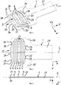
Figure 1 shows a perspective view of an electric connection arrangement with afemale terminal 1 and amale terminal 2. Thefemale terminal 1 and themale terminal 2 are shown in a fully mated condition, in which they are in electrical contact to each other. Thefemale terminal 1 has aconnection portion 27 that is connected to aconductor 29 of afirst cable 30. Themale terminal 2 has aconnection portion 28 that is connected to aconductor 31 of asecond cable 32. - The
female terminal 1 can best be seen inFigures 2 to 5 , which are described together hereinafter. Thefemale terminal 1 has a receivingspace 3 extending in direction of a longitudinal axis L of the connection arrangement. As shown inFigure 1 themale terminal 2 can be inserted into the receivingspace 3 in a mating direction M parallel to the longitudinal axis L and towards thefemale terminal 1. The receivingspace 3 is delimited byupper lamellae 4 andlower lamellae 5. Theupper lamellae 4 each have aninner surface 6 facing the receivingspace 3. Thelower lamellae 5 each have aninner surface 7 facing the receivingspace 3. - The
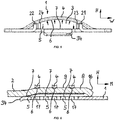
upper lamellae 4 and thelower lamellae 5 extent traverse to the longitudinal axis L. Theinner surfaces 6 of theupper lamellae 4 are concave in a direction traverse to the longitudinal axis L. In the disclosed embodiment, theinner surfaces 7 of thelower lamellae 5 are straight and arranged in one common plane E. - Alternatively, also the
inner surfaces 7 of thelower lamellae 5 may be concave in a direction traverse to the longitudinal axis L. - The
upper lamellae 4 and thelower lamellae 5 are cut out of a piece of sheet metal extending in the plane E. According to the disclosed example sixparallel slots 17 are cut into the sheet metal forming theupper lamellae 4 and thelower lamellae 5 alternately in mating direction M. Theupper lamellae 4 are then bent and formed into a curved shape so that theupper lamellae 4 project from the plane E in a height direction. Accordingly, the entireupper lamellae 4 are formed concave towards the receivingspace 3 and convex in the opposite orientation away from the receivingspace 3, all in a plane traverse to the longitudinal axis L. - At opposite ends in width direction W, the
upper lamellae 4 and thelower lamellae 5 are integrally connected tolateral portions female terminal 1. Thelateral portions lower lamellae 5 are arranged in the common plane E. - The mentioned directions refer to a mating direction M, a height direction H and a width direction W of a Cartesian coordinate system.
- The
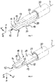
male terminal 2 can best be seen inFigures 7 to 9 , which are described together hereinafter. Themale terminal 2 has ablade 8 that can be inserted into the receivingspace 3 of thefemale terminal 1 as disclosed inFigure 1 . For mating thefemale terminal 1 and themale terminal 2, theblade 8 is inserted into the receivingspace 3 in the mating direction M that is parallel to the longitudinal axis L. - The
blade 8 has anupper surface 9 that is formed convex traverse to the longitudinal axis L, and that is, in the fully mated condition of the connection arrangement as shown inFigure 1 , in contact with theinner surfaces 6 of theupper lamellae 4, thereby establishing a line contact between theupper surface 9 of theblade 8 and theinner surfaces 6 of theupper lamellae 4. In practice, theblade 8 will touch theupper lamellae 4 at a large number of contact points with at least a tendency towards a line contact. In order to increase the contact pressure between theupper lamellae 4 and theblade 8, theupper lamellae 4 can be formed as shown inFigures 4 and6 withinner surfaces 6 being convex in the direction of the longitudinal axis L. Thereby, the width of the line of the line contact in the mating direction M is decreased resulting in a higher contact pressure. In the shown example, even the entireupper lamellae 4 are curved. Alternatively, the surfaces of theupper lamellae 4 opposite theinner surfaces 6 of theupper lamellae 4 may be straight in the mating direction M. - In the shown example, the
blade 8 is made from a sheet metal material and is formed to have a curved cross-section. Theblade 8 is convex towards theupper lamellae 4 and concave towards thelower lamellae 5 viewed in a plane defined by the height direction H and the width direction W. Hence, theblade 8 has twolower surfaces inner surfaces 7 of thelower lamellae 5. Theblade 8 is clamped between theupper lamellae 4 and thelower lamellae 5. - In the shown exemplary embodiment the
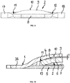
blade 8 is spoon shaped so that it has a curved cross-section in a plane perpendicular to the longitudinal axis L as well as a curved cross-section in a plane perpendicular to the width direction W. This facilitates a simple manufacturing of theblade 8 wherein themale terminal 2 is also provided with the lead-in zone having a slantedupper surface portion 16 at afront end 15 of themale terminal 2 in a single manufacturing step, e.g. by forming. The lead-in zone makes it easier to insert theblade 8 into the receivingspace 3 at the beginning of the mating procedure. - In the cross-sectional view according to
Figures 9 and 10 showing the cross-section of theblade 8 in a plane defined by the height direction H and the width direction W, it can be seen that in the disclosed embodiment theupper surface 9 has acentral surface region 10 that is arranged between twoperipheral surface regions -
Figure 10 shows a cross-sectional view perpendicular to the longitudinal axis L of the connection arrangement. Theblade 8 of themale terminal 2 to and thefemale terminal 1 are shown in a non-deformed state. Thecentral surface region 10 is that region of theupper surface 9 of theblade 8 which overlaps with theupper lamellae 4. Theperipheral surface regions upper surface 9 of the blade which do not overlap with theupper lamellae 4. Alternatively, the entireupper surface 9 can overlap with theupper lamellae 4 without peripheral regions. - In the disclosed embodiment, when the
blade 8 is inserted into the receivingspace 3 of thefemale terminal 1, theupper lamellae 4 and thelower lamellae 5 are elastically deformed such that their shape, and hence the cross-section of the receivingspace 3, adjusts to the shape of theblade 8 of themale terminal 2 thus compensating an overlap in the height direction H. In particular, theupper lamellae 4 may be stretched and bent as described hereinafter. Further, theblade 8 may be compressed in the height direction H. However, in order to explain why theupper lamellae 4 and theblade 8 are elastically deformed these are shown inFigure 10 in a non-deformed state. - The
blade 8 contacts theinner surfaces 7 of thelower lamellae 5. Theblade 8 has a first height H1 in height direction H that is greater than a second height H2 of the receivingspace 3 in height direction H, thereby creating an overlap O between theblade 8 and theupper lamellae 4. - The overlap O results in a force against the
upper lamellae 4 onto theinner surfaces 6 thereof as well as forces from theblade 8 onto theinner surfaces 7 of thelower lamellae 5, as indicated by arrows shown inFigure 5 . Thereby theupper lamellae 4 are elastically deformed, for instance stretched in a direction of their extension and slightly bent in a direction travers the stretching direction. - The
male terminal 2 is provided withtabs tab stop face front end 15 of themale terminal 2 and towards thefemale terminal 1. - At a
front end 33, thefemale terminal 1 has twotabs stop face Figure 1 , eachstop face male terminal 1 abuts one of the stop faces 37, 38 of thefemale terminal 1 in order to avoid that themale terminal 2 is inserted too far into the receivingspace 3 of thefemale terminal 1. - The distance between the
tabs female terminal 1 is greater than the width of theblade 8 of themale terminal 2 over a large part of the longitudinal extension of theblade 8 starting from itsfront end 15. In the real part of theblade 8, adjacent to thelateral tabs blade 8 continuously increases towards thetabs blade 8 to thelateral tabs blade 8 is approximately identical or only slightly smaller than the distance between the twotabs front end 33 of thefemale terminal 1. - The
tabs front end 33 of thefemale terminal 1 facilitate the insertion of themale terminal 2 into the receivingspace 3 by laterally guiding theblade 8. Further, at thefront end 33 thefemale terminal 1 has a guidingflap 34, which projects in a direction of the longitudinal axis L opposite the mating direction M.The guiding flap 34 is bent out of the plane E in an opposite direction than thetabs blade 8 of themale terminal 2 into the receivingspace 3. - The
female terminal 1 is further provided with two guidingtabs surface tabs blade 8 over a large part of the longitudinal extension between thefront end 15 of theblade 8 and the region of theblade 8, which has an increasing width. Thereby, during at least the final movement of theblade 8 into the receivingspace 3,blade 8 is laterally guided by the guidingtabs female terminal 1. - The
tabs tabs female terminal 1 so that they are parallel to the height direction H and project, viewed in the longitudinal axis L, into the receivingspace 3. -
- 1
- female terminal
- 2
- male terminal
- 3
- receiving space
- 4
- upper lamella
- 5
- lower lamella
- 6
- inner surface of upper lamella
- 7
- inner surface of lower lamella
- 8
- blade
- 9
- upper surface of the blade
- 10
- central surface region
- 11
- peripheral surface region
- 12
- peripheral surface region
- 13
- lower surface of the blade
- 14
- lower surface of the blade
- 15
- front end of the male terminal
- 16
- slanted upper surface section
- 17
- tab of the blade
- 18
- tab of the blade
- 19
- stop face
- 20
- stop face
- 21
- tab of the female terminal
- 22
- tab of the female terminal
- 23
- guiding tab
- 24
- guiding tab
- 25
- guiding surface
- 26
- guiding surface
- 27
- connection portion
- 28
- connection portion
- 29
- conductor
- 30
- first cable
- 31
- conductor
- 32
- second cable
- 33
- front end of the female terminal
- 34
- guiding flap
- 35
- lateral portion
- 36
- lateral portion
- 37
- stop face
- 38
- stop face
- H
- height direction
- H1
- first height
- H2
- second height
- L
- longitudinal axis
- M
- mating direction
- W
- width direction
Claims (13)
- Electric connection arrangement comprising:a female terminal (1) having a receiving space (3) extending in direction of a longitudinal axis (L) of the connection arrangement and being delimited by upper lamellae (4) and lower lamellae (5), wherein the upper lamellae (4) each have an inner surface (6) facing the receiving space (3), and wherein the lower lamellae (5) each have an inner surface (7) facing the receiving space (3),a male terminal (2) having a blade (8) that is received within the receiving space (3) in a mated condition of the connection arrangement,characterized inthat the upper lamellae (4) and the lower lamellae (5) extend traverse to the longitudinal axis (L),that the inner surfaces (6) of the upper lamellae (4) are concave in a direction traverse to the longitudinal axis (L), andthat the blade (8) has an upper surface (9) being formed convex in a direction traverse to the longitudinal axis (L) and which is, in the mated condition of the connection arrangement, in contact with the concave inner surfaces (6) of the upper lamellae (4).
- Electric connection arrangement according to claim 1,
characterized in
that the inner surfaces (7) of the lower lamellae (5) are straight and arranged in one common plane (E). - Electric connection arrangement according to claim 1 or 2,
characterized in
that the blade (8) of the male terminal (2) has a curved cross-section. - Electric connection arrangement according to any one of claims 1 to 3,
characterized in
that the male terminal (2) has a front end (15) facing the female terminal (1), and
that at the front end (15) the male terminal (2) has a lead-in zone with a slanted upper surface portion (16). - Electric connection arrangement according to any one of claims 1 to 4,
characterized in
that the blade (8) of the male terminal (2) is spoon-shaped. - Electric connection arrangement according to any one of claims 1 to 5,
characterized in
that the maximum height (H2) in a height direction (H) between the upper lamellae (4) and the lower lamellae (5) is smaller than the height (H1) of the blade (8) in the height direction (H). - Electric connection arrangement according to any one of claims 1 to 6,
characterized in
that the upper lamellae (4) and the lower lamellae (5) are integrally cut out of a flat sheet metal material. - Electric connection arrangement according to any one of claims 1 to 7,
characterized in
that upper lamellae (4) and lower lamellae (5) are arranged alternately in direction of the longitudinal axis (L). - Electric connection arrangement according to any one of claims 1 to 8,
characterized in
that the inner surfaces (6) of the upper lamellae (4) are formed convex in direction of the longitudinal axis (L). - Electric connection arrangement according to any one of claims 1 to 9,
characterized in
that the male terminal (2) has a stop face (19, 20) being in contact with a stop face (37, 38) of the female terminal (1) in the mated condition. - Electric connection arrangement according to any one of claims 1 to 10,
characterized in
that the female terminal (1) has guiding surfaces (25, 26) guiding the blade (8) of the male terminal (2) while being inserted into the receiving space (3). - Electric connection arrangement according to claim 11,
characterized in
that the female terminal (2) has guiding tabs (23, 24) which have the guiding surfaces (25, 26) and which project into the receiving space (3). - Electric connection arrangement according to any one of claims 1 to 12,
characterized in
that the male terminal (2) and the female terminal (1) each have a connection portion (27, 28) for connecting conductors (29, 31) of electric cables (30, 32) to the connection portions (27, 28).
Priority Applications (1)
| Application Number | Priority Date | Filing Date | Title |
|---|---|---|---|
| EP19193311.8A EP3783744A1 (en) | 2019-08-23 | 2019-08-23 | Electric connection arrangement |
Applications Claiming Priority (1)
| Application Number | Priority Date | Filing Date | Title |
|---|---|---|---|
| EP19193311.8A EP3783744A1 (en) | 2019-08-23 | 2019-08-23 | Electric connection arrangement |
Publications (1)
| Publication Number | Publication Date |
|---|---|
| EP3783744A1 true EP3783744A1 (en) | 2021-02-24 |
Family
ID=67742229
Family Applications (1)
| Application Number | Title | Priority Date | Filing Date |
|---|---|---|---|
| EP19193311.8A Pending EP3783744A1 (en) | 2019-08-23 | 2019-08-23 | Electric connection arrangement |
Country Status (1)
| Country | Link |
|---|---|
| EP (1) | EP3783744A1 (en) |
Citations (6)
| Publication number | Priority date | Publication date | Assignee | Title |
|---|---|---|---|---|
| US3107966A (en) | 1958-02-28 | 1963-10-22 | Curtiss Wright Corp | Electrical connector socket |
| US20050118891A1 (en) | 2003-11-28 | 2005-06-02 | J. S. T. Mfg. Co., Ltd. | Female terminal for heavy current and female terminal for heavy current with shell |
| EP1401056B1 (en) * | 2002-09-19 | 2006-05-10 | Neutrik Aktiengesellschaft | Socket of an electrical connection |
| US20080293287A1 (en) * | 2007-04-03 | 2008-11-27 | Lear Corporation | Electrical terminal assembly and method of using the electrical terminal assembly |
| US9793620B2 (en) * | 2015-08-31 | 2017-10-17 | Te Connectivity Germany Gmbh | Connector assembly with a blade connector |
| EP3051635B1 (en) * | 2015-01-30 | 2018-01-17 | TE Connectivity Germany GmbH | Electric contact means and electrical cable assembly for the automotive industry |
-
2019
- 2019-08-23 EP EP19193311.8A patent/EP3783744A1/en active Pending
Patent Citations (6)
| Publication number | Priority date | Publication date | Assignee | Title |
|---|---|---|---|---|
| US3107966A (en) | 1958-02-28 | 1963-10-22 | Curtiss Wright Corp | Electrical connector socket |
| EP1401056B1 (en) * | 2002-09-19 | 2006-05-10 | Neutrik Aktiengesellschaft | Socket of an electrical connection |
| US20050118891A1 (en) | 2003-11-28 | 2005-06-02 | J. S. T. Mfg. Co., Ltd. | Female terminal for heavy current and female terminal for heavy current with shell |
| US20080293287A1 (en) * | 2007-04-03 | 2008-11-27 | Lear Corporation | Electrical terminal assembly and method of using the electrical terminal assembly |
| EP3051635B1 (en) * | 2015-01-30 | 2018-01-17 | TE Connectivity Germany GmbH | Electric contact means and electrical cable assembly for the automotive industry |
| US9793620B2 (en) * | 2015-08-31 | 2017-10-17 | Te Connectivity Germany Gmbh | Connector assembly with a blade connector |
Similar Documents
| Publication | Publication Date | Title |
|---|---|---|
| US10381766B2 (en) | Terminal fitting | |
| US4416504A (en) | Contact with dual cantilevered arms with narrowed, complimentary tip portions | |
| EP2461431B1 (en) | Dual contact beam terminal | |
| EP2375506A1 (en) | Terminal fitting connecting structure | |
| US11075479B2 (en) | Terminal fitting | |
| EP0944130A2 (en) | Crimp connection | |
| EP2738885A1 (en) | Crimping die and method for manufacturing electric wire with terminal | |
| EP0390889B1 (en) | Electrical connector | |
| KR960016876B1 (en) | Male electrical terminal with anti-overstress means | |
| US5462459A (en) | Spring-type electrical receptacle | |
| EP0952631A2 (en) | Male contact | |
| EP2755280A1 (en) | Crimp contact and cable assembly including the same | |
| JPH0371741B2 (en) | ||
| US4983130A (en) | Insulation displacement contact | |
| US10644424B2 (en) | Connector terminal, connector including the connector terminal, and method for producing the connector terminal | |
| EP3783744A1 (en) | Electric connection arrangement | |
| KR970000120B1 (en) | High contact pressure insulation displacement terminal for multi-strand wire | |
| WO2000059073A1 (en) | Female electrical terminal with arc arresting portion | |
| US10707586B2 (en) | Wire with terminal | |
| WO2011021298A1 (en) | Female terminal fitting | |
| EP2859622B1 (en) | Terminal connection structure | |
| KR102338051B1 (en) | Coaxial Connectors and Coaxial Connectors with Coaxial Cables | |
| US11652316B2 (en) | Retention clip for a mechanical strain relief of a cable | |
| US11349241B2 (en) | Power socket for electrical connector system | |
| EP3989363A1 (en) | Electrical crimp terminal |
Legal Events
| Date | Code | Title | Description |
|---|---|---|---|
| PUAI | Public reference made under article 153(3) epc to a published international application that has entered the european phase |
Free format text: ORIGINAL CODE: 0009012 |
|
| STAA | Information on the status of an ep patent application or granted ep patent |
Free format text: STATUS: THE APPLICATION HAS BEEN PUBLISHED |
|
| AK | Designated contracting states |
Kind code of ref document: A1 Designated state(s): AL AT BE BG CH CY CZ DE DK EE ES FI FR GB GR HR HU IE IS IT LI LT LU LV MC MK MT NL NO PL PT RO RS SE SI SK SM TR |
|
| AX | Request for extension of the european patent |
Extension state: BA ME |
|
| STAA | Information on the status of an ep patent application or granted ep patent |
Free format text: STATUS: REQUEST FOR EXAMINATION WAS MADE |
|
| 17P | Request for examination filed |
Effective date: 20210824 |
|
| RBV | Designated contracting states (corrected) |
Designated state(s): AL AT BE BG CH CY CZ DE DK EE ES FI FR GB GR HR HU IE IS IT LI LT LU LV MC MK MT NL NO PL PT RO RS SE SI SK SM TR |
|
| STAA | Information on the status of an ep patent application or granted ep patent |
Free format text: STATUS: EXAMINATION IS IN PROGRESS |
|
| 17Q | First examination report despatched |
Effective date: 20221103 |
|
| RAP3 | Party data changed (applicant data changed or rights of an application transferred) |
Owner name: YAZAKI EUROPE LTD. |