JP2005152659A - Support device of washing machine - Google Patents
Support device of washing machine Download PDFInfo
- Publication number
- JP2005152659A JP2005152659A JP2004344142A JP2004344142A JP2005152659A JP 2005152659 A JP2005152659 A JP 2005152659A JP 2004344142 A JP2004344142 A JP 2004344142A JP 2004344142 A JP2004344142 A JP 2004344142A JP 2005152659 A JP2005152659 A JP 2005152659A
- Authority
- JP
- Japan
- Prior art keywords
- washing machine
- spring
- support
- support leg
- base
- Prior art date
- Legal status (The legal status is an assumption and is not a legal conclusion. Google has not performed a legal analysis and makes no representation as to the accuracy of the status listed.)
- Pending
Links
Images


Classifications
-
- D—TEXTILES; PAPER
- D06—TREATMENT OF TEXTILES OR THE LIKE; LAUNDERING; FLEXIBLE MATERIALS NOT OTHERWISE PROVIDED FOR
- D06F—LAUNDERING, DRYING, IRONING, PRESSING OR FOLDING TEXTILE ARTICLES
- D06F37/00—Details specific to washing machines covered by groups D06F21/00 - D06F25/00
- D06F37/20—Mountings, e.g. resilient mountings, for the rotary receptacle, motor, tub or casing; Preventing or damping vibrations
-
- D—TEXTILES; PAPER
- D06—TREATMENT OF TEXTILES OR THE LIKE; LAUNDERING; FLEXIBLE MATERIALS NOT OTHERWISE PROVIDED FOR
- D06F—LAUNDERING, DRYING, IRONING, PRESSING OR FOLDING TEXTILE ARTICLES
- D06F39/00—Details of washing machines not specific to a single type of machines covered by groups D06F9/00 - D06F27/00
- D06F39/12—Casings; Tubs
- D06F39/125—Supporting arrangements for the casing, e.g. rollers or legs
-
- F—MECHANICAL ENGINEERING; LIGHTING; HEATING; WEAPONS; BLASTING
- F16—ENGINEERING ELEMENTS AND UNITS; GENERAL MEASURES FOR PRODUCING AND MAINTAINING EFFECTIVE FUNCTIONING OF MACHINES OR INSTALLATIONS; THERMAL INSULATION IN GENERAL
- F16M—FRAMES, CASINGS OR BEDS OF ENGINES, MACHINES OR APPARATUS, NOT SPECIFIC TO ENGINES, MACHINES OR APPARATUS PROVIDED FOR ELSEWHERE; STANDS; SUPPORTS
- F16M7/00—Details of attaching or adjusting engine beds, frames, or supporting-legs on foundation or base; Attaching non-moving engine parts, e.g. cylinder blocks
Abstract
Description
本発明は、洗濯機の支持装置に関し、詳しくは、別途の手動操作なしに全てのフットが底面に接触する、洗濯機の設置が便利であり、騷音及び振動を低減できる洗濯機の支持装置に関する。 The present invention relates to a washing machine support device, and more particularly, a washing machine support device in which all the feet are in contact with the bottom surface without separate manual operation, the installation of the washing machine is convenient, and noise and vibration can be reduced. About.
図21は一般的な洗濯機を示した斜視図である。
一般に、洗濯機は、前方に洗濯物を出し入れする出入口150を開閉するドア152が装着されるキャビネット156と、前記キャビネット156の内部に多数の減衰器158により支持されて洗濯水を保存するタブ160と、前記タブ160の内部に回転自在に配置されて洗濯物の洗濯及び脱水作用をするドラム162と、前記タブ160の後方に設置され、前記ドラム162と駆動軸により連結されて前記ドラム162を回転させる駆動モータ164と、前記キャビネット156の四つの角に装着されて洗濯機全体を支持する支持装置170と、から構成されている。
FIG. 21 is a perspective view showing a general washing machine.
In general, the washing machine includes a
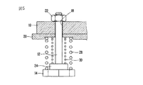
図22は従来の洗濯機の支持装置を示した断面図である。
従来の洗濯機の支持装置170は、前記キャビネット156の下面に固定されて雌ねじ部174が貫通形成される取付けブラケット172と、前記取付けブラケット172に螺合するように外周面に雄ねじ部178が形成され、締めるか外すと、上下方向に移動しながら高さが調節される支持レッグ176と、前記支持レッグ176の下端に形成されて底面に接触するフット180と、から構成される。
FIG. 22 is a cross-sectional view showing a conventional washing machine support apparatus.
The conventional washing
このような従来の洗濯機の支持装置170は、洗濯機を設置しようとする底面に位置した後、使用者が支持レッグ176を回転すると、前記支持レッグ176の雄ねじ部178が取付けブラケット172の雌ねじ部174と共に上下方向に直線移動しながら洗濯機の水平を調整する。
When the user rotates the
然るに、従来の洗濯機の支持装置は、洗濯機が設置される底面の高さが不均一である場合、使用者が支持レッグを外すか締めることで、手動で各支持装置の高さを調節して洗濯機の均衡を保持しなければならないため、調整作業が煩雑であり、特に洗濯機の設置空間が狭くて使用者の手が届きにくい場合は、支持装置の高さを調節することが困難であるという問題点があった。 However, in the conventional washing machine support device, when the height of the bottom surface where the washing machine is installed is uneven, the user manually adjusts the height of each support device by removing or tightening the support leg. Since the balance of the washing machine must be maintained, the adjustment work is complicated, especially when the installation space of the washing machine is small and difficult for the user to reach. There was a problem that it was difficult.
また、支持装置の高さ調節が正確でない場合、何れか一つのフットが底面に接しないと、洗濯機の駆動時、底面に接しないフットが底面を打つことで衝撃が発生し、大きな振動及び騷音が発生するという問題点があった。 In addition, when the height adjustment of the support device is not accurate, if any one foot does not contact the bottom surface, when the washing machine is driven, the foot that does not contact the bottom surface strikes the bottom surface, and an impact is generated. There was a problem of stuttering.
本発明は、このような従来の課題に鑑みてなされたもので、洗濯機の設置時に別途の高さ調整が不要であり、洗濯機を底面に設置すると洗濯機の水平が自動的で調整される、作業が便利な洗濯機の支持装置を提供することを目的とする。
また、支持装置の各フットが、底面の不均一に関係なく常に底面に接触することによって、洗濯機の駆動時に発生する騷音及び振動を減少できる洗濯機の支持装置を提供することを目的とする。
The present invention has been made in view of such conventional problems, and does not require a separate height adjustment when the washing machine is installed. When the washing machine is installed on the bottom surface, the level of the washing machine is automatically adjusted. An object of the present invention is to provide a washing machine support device that is convenient to operate.
Another object of the present invention is to provide a washing machine support device in which each foot of the support device is always in contact with the bottom surface regardless of unevenness of the bottom surface, thereby reducing noise and vibration generated when the washing machine is driven. To do.
また、支持装置に減衰装置を装着することで、洗濯機の駆動時に発生する振動及び騷音を低減できる洗濯機の支持装置を提供することを目的とする。 It is another object of the present invention to provide a washing machine support device that can reduce vibration and noise generated when the washing machine is driven by attaching a damping device to the support device.
このような目的を達成するため、本発明に係る洗濯機の支持装置は、洗濯機本体の下側に固定されるベースに少なくとも一つが上下方向移動可能に装着される多数の支持レッグと、前記支持レッグの下端に装着されて底面に接触するフットと、前記ベースとフットとの間に装着されて前記フットに弾性を与えるスプリングとを含むことを特徴とする。 In order to achieve such an object, the washing machine support device according to the present invention includes a plurality of support legs mounted on a base fixed to the lower side of the washing machine main body so that at least one of the support legs is vertically movable. The foot includes a foot that is attached to the lower end of the support leg and contacts the bottom surface, and a spring that is attached between the base and the foot and gives elasticity to the foot.
好適には、前記ベースには前記支持レッグが上下方向移動自在に挿入される貫通孔が形成され、前記スプリングの上端を支持する取付けブラケットが装着されている。 Preferably, the base is formed with a through hole into which the support leg is inserted so as to be movable in the vertical direction, and a mounting bracket for supporting the upper end of the spring is mounted.
好適には、前記支持レッグの上側には、前記貫通孔から支持レッグが離脱されることを防止する離脱防止用ナットが締結されている。 Preferably, a detachment prevention nut for preventing the support leg from being detached from the through hole is fastened to the upper side of the support leg.
好適には、前記フットの上面には前記スプリングの下端が支持されるとともに前記支持レッグが固定される座部材が装着されている。 Preferably, a seat member to which the lower end of the spring is supported and the support leg is fixed is mounted on the upper surface of the foot.
好適には、前記スプリングは、相互に異なる弾性を有する第1スプリング及び第2スプリングを含み、前記第1スプリング及び第2スプリングは、荷重が加わらない状態でその長さ及びばね定数が相互に異なるように形成されている。 Preferably, the spring includes a first spring and a second spring having mutually different elasticity, and the first spring and the second spring have different lengths and spring constants when no load is applied. It is formed as follows.
好適形態において、前記ベースの上面には、前記支持レッグが挿入される貫通孔に異物質や埃が流入することを防止するキャップが装着されている。前記キャップは、前記貫通孔が形成されるベースの上面に固定され、かつその内部で前記支持レッグが上方に移動する程度の高さを有することが望ましい。 In a preferred embodiment, a cap that prevents foreign substances and dust from flowing into the through hole into which the support leg is inserted is attached to the upper surface of the base. The cap is preferably fixed to the upper surface of the base in which the through hole is formed, and has a height that allows the support leg to move upward.
好適には、前記フットと支持レッグとの間には、前記フットを支持レッグに枢軸回転(pivot)自在に連結するジョイント部が装着され、前記ジョイント部は、支持レッグの端部に形成されるボールと、前記ボールが転動自在に挿入される半球状の溝が形成されているとともにフットが装着される支持部材と、前記支持部材の上側に装着されて前記ボールが支持部材から離脱されることを防止するカバーとを含む。 Preferably, a joint portion that pivotally connects the foot to the support leg is pivotally mounted between the foot and the support leg, and the joint portion is formed at an end portion of the support leg. A ball, a hemispherical groove into which the ball is rotatably inserted, a support member to which a foot is mounted, and a ball mounted on the upper side of the support member so that the ball is detached from the support member; And a cover for preventing this.
好適には、前記カバーは前記支持部材の上側に結合され、前記カバーの中央には前記支持レッグが通過する貫通孔と、前記ボールを転動自在に取り囲む半球状の溝とが形成されている。 Preferably, the cover is coupled to the upper side of the support member, and a through-hole through which the support leg passes and a hemispherical groove that freely rolls around the ball are formed in the center of the cover. .
好適には、前記スプリングとベースとの間には、減衰作用をする減衰部材が装着され、前記ベースの下面には前記スプリングが上下方向に圧縮変形するように誘導するガイド部材が設けられている。 Preferably, a damping member that performs a damping action is mounted between the spring and the base, and a guide member that guides the spring to compress and deform in the vertical direction is provided on the lower surface of the base. .
好適形態において、前記ベースの下面には前記減衰部材を収容する収容溝が形成され、かつ前記減衰部材とスプリングの上面との間にはスプリング座が装着されている。 In a preferred embodiment, a housing groove for housing the damping member is formed on the lower surface of the base, and a spring seat is mounted between the damping member and the upper surface of the spring.
更に、本発明に係る他の形態の洗濯機の支持装置は、洗濯機本体の下側に固定されるベースに上下方向移動可能に装着された多数の支持レッグと、前記支持レッグの下端に装着されて底面に接触するフットと、前記ベースとフットとの間に装着されて前記フットに弾性を与えるスプリングと、前記スプリングの上面及びベースの上面に装着されて、洗濯機の駆動時に発生する前記スプリングの共振を抑制して振動を低減する減衰ユニットとを含むことを特徴とする。 Furthermore, a washing machine support device according to another aspect of the present invention includes a plurality of support legs mounted on a base fixed to the lower side of the washing machine main body so as to be movable in the vertical direction, and mounted on a lower end of the support leg. A foot that contacts the bottom surface, a spring that is mounted between the base and the foot to give elasticity to the foot, and is mounted on the upper surface of the spring and the upper surface of the base, and is generated when the washing machine is driven. And a damping unit that reduces vibration by suppressing resonance of the spring.
好適には、前記減衰ユニットは、前記ベースの上面に締結され、かつ内部に空間を有して上側に支持レッグが通過する貫通孔が形成されたハウジングと、前記ハウジングの内部に配置され、かつ前記支持レッグに締結されて前記支持レッグと共に上下方向に移動してスプリングの下端を支持する第1座部材と、前記ハウジングの内側上部に設置されて前記スプリングの上端を支持する第2座部材と、前記第1座部材の外周面に固定されて前記ハウジングの内周面に摩擦する摩擦部材とを含む。 Preferably, the attenuation unit is fastened to the upper surface of the base, and has a housing formed with a through hole through which a support leg passes on the upper side, and is disposed inside the housing. A first seat member fastened to the support leg and moved up and down together with the support leg to support a lower end of a spring; a second seat member installed on an inner upper portion of the housing to support the upper end of the spring; And a friction member fixed to the outer peripheral surface of the first seat member and rubbed against the inner peripheral surface of the housing.
好適には、前記ハウジングの上部内面と前記第2座部材との間には、緩衝作用をする緩衝部材が装着されている。 Preferably, a buffer member that performs a buffering action is mounted between the upper inner surface of the housing and the second seat member.
好適には、前記摩擦部材はその内周面が前記第1座部材の外周面に挟まれ、その外周面がハウジングの内周面に摩擦するように配置されている。 Preferably, the friction member is disposed such that an inner peripheral surface thereof is sandwiched between outer peripheral surfaces of the first seat member and the outer peripheral surface is rubbed against the inner peripheral surface of the housing.
好適形態において、前記減衰ユニットは、前記ベースの上面に締結されかつ内部に空間を有して上側に支持レッグが通過する貫通孔が形成されるハウジングと、前記ハウジングの下部に配置されてスプリングの下端を支持する第1座部材と、前記ハウジングの内側上部に設置されて前記スプリングの上端を支持する第2座部材と、前記第1座部材の下側に設置され、かつ前記支持レッグに固定されて共に上下方向に移動する支持部材と、前記支持部材の外周面に固定されて前記ハウジングの内周面に摩擦する摩擦部材とを含む。 In a preferred embodiment, the damping unit includes a housing that is fastened to the upper surface of the base and has a space in the interior thereof, and a through hole through which a support leg passes is formed on the upper side. A first seat member that supports a lower end; a second seat member that is installed on an inner upper portion of the housing and supports an upper end of the spring; and is installed on a lower side of the first seat member and is fixed to the support leg And a support member that moves in the vertical direction, and a friction member that is fixed to the outer peripheral surface of the support member and rubs against the inner peripheral surface of the housing.
前記支持部材と第1座部材との間には、減衰作用をする減衰部材が装着されていることが望ましい。 It is desirable that a damping member that performs a damping action is mounted between the support member and the first seat member.
更に、本発明に係る他の形態の洗濯機の支持装置は、洗濯機本体の下側に固定されるベースに上下方向移動可能に装着された多数の支持レッグと、前記支持レッグの下端に装着されて底面に接触するフットと、前記ベースとフットとの間に装着されて前記フットに弾性を与えるスプリングと、前記ベースの一側に装着されて、洗濯機の駆動時に前記支持レッグの上下方向移動をロッキングするロッキングユニットとを含むことを特徴とする。 Furthermore, a washing machine support device according to another aspect of the present invention includes a plurality of support legs mounted on a base fixed to the lower side of the washing machine main body so as to be movable in the vertical direction, and mounted on a lower end of the support leg. A foot that is in contact with the bottom surface, a spring that is mounted between the base and the foot to give elasticity to the foot, and is mounted on one side of the base so that the support leg is vertically driven when the washing machine is driven. And a locking unit for locking movement.
好適には、前記ロッキングユニットは、前記支持レッグに対して直角方向に直線移動可能に配置され、その端が前記支持レッグの側面に密着して前記支持レッグの長手方向移動をロッキングするプッシュロッドと、前記プッシュロッドが直線移動可能に装着され、かつ電源が印加されると前記プッシュロッドを移動させるアクチュエーターとを含む。 Preferably, the locking unit is arranged so as to be linearly movable in a direction perpendicular to the support leg, and a push rod whose end closely contacts a side surface of the support leg and locks the longitudinal movement of the support leg; And an actuator that moves the push rod when the power is applied.
好適形態において、前記支持レッグの側面には長手方向にテーパー溝が形成され、かつ前記プッシュロッドの端部には前記テーパー溝に挿入されるテーパー突起が形成されている。 In a preferred embodiment, a taper groove is formed in a longitudinal direction on a side surface of the support leg, and a taper protrusion inserted into the taper groove is formed on an end portion of the push rod.
前記アクチュエーターは、電源が印加されるとプッシュロッドを押すソレノイドタイプであってよい。 The actuator may be a solenoid type that pushes a push rod when a power is applied.
好適形態において、前記プッシュロッドの端部には前記支持レッグの外周面から所定間隔を置いてリングが一体形成され、かつ前記リングの内周面には前記支持レッグの外周面に摩擦する摩擦部材が装着されている。 In a preferred embodiment, a ring is integrally formed at an end of the push rod at a predetermined interval from the outer peripheral surface of the support leg, and a friction member that frictions against the outer peripheral surface of the support leg is formed on the inner peripheral surface of the ring. Is installed.
本発明に係る洗濯機の支持装置は、洗濯機を底面に設置すると、スプリングの弾性により洗濯機の水平が自動的で調整されるために、洗濯機の設置時に別途の高さ調整が不要であり、作業が便利であるという効果がある。 When the washing machine is installed on the bottom surface, the washing machine support device according to the present invention automatically adjusts the level of the washing machine due to the elasticity of the spring. Therefore, no separate height adjustment is required when installing the washing machine. There is an effect that the work is convenient.
また、支持装置の各フットが、スプリングの弾性により底面の不均一に関係なく常に底面に接触するために、洗濯機の駆動時に発生する騷音及び振動を減少できるという効果がある。 In addition, since each foot of the support device is always in contact with the bottom surface regardless of the unevenness of the bottom surface due to the elasticity of the spring, it is possible to reduce the noise and vibration generated when the washing machine is driven.
また、支持装置に減衰ユニットを備えることで、洗濯機の駆動時に発生する振動及び騷音を低減できるという効果がある。 Further, by providing the support device with the attenuation unit, there is an effect that vibration and noise generated when the washing machine is driven can be reduced.
以下、本発明の実施形態に関し、図面に基づいて説明する。
図1及び図2は本発明の第1実施形態に係る洗濯機の支持装置を示した斜視図であり、図3は本発明の第1実施形態に係る洗濯機の支持装置を示した断面図である。
Hereinafter, embodiments of the present invention will be described with reference to the drawings.
1 and 2 are perspective views showing a washing machine support device according to the first embodiment of the present invention, and FIG. 3 is a cross-sectional view showing the washing machine support device according to the first embodiment of the present invention. It is.
第1実施形態に係る洗濯機の支持装置は、キャビネット156の下側に固定され、四つの角部に垂直方向に貫通孔18がそれぞれ形成されたベース10と、前記ベース10の貫通孔18に上下方向に直線移動自在に挿入される支持レッグ12と、前記支持レッグ12の下端に装着されて底面に接触するフット14と、前記ベース10とフット14との間に装着されてフット14に所定弾性を与えるスプリング16と、から構成される。
The supporting device of the washing machine according to the first embodiment is fixed to the lower side of the
前記ベース10の下側には、支持レッグ12が通過する貫通孔18が形成され、スプリング16の上端を支持する取付けブラケット20が装着される。前記取付けブラケット20は、スプリング16の上端を支持する程度の剛性を有する金属材質により形成される。
A through
前記支持レッグ12は、貫通孔18に挿入されて上下方向のみに移動し、左右方向には移動しないようにする。また、前記支持レッグ12は、ベース10の上側に突出されるとともに、取付けブラケット20の下側方向に突出される程度の長さを有し、その上部には、前記支持レッグ12がベース10から離脱することを防止する離脱防止用ナット22が締結される。
The
前記フット14は、平板状に形成されており、底面に接触して滑りを防止するゴム材料により形成される。また、前記フット14の上面には、支持レッグ12が固定されるとともに、前記スプリング16の下端を支持する座部材24が固定される。
The
前記スプリング14は、フット14に弾性を与えるコイルスプリングにより形成され、その一端が前記取付けブラケット20の下端に支持され、他端は前記フット14に固定された座部材24に支持される。
The
以下、このように構成される本発明の第1実施形態に係る洗濯機の支持装置の作用を説明する。
まず、洗濯機を設置場所に配置すると、ベース10の四つの角部に装着された支持装置により底面に対して洗濯機が支持され、前記底面の高さが不均一である場合も、使用者が支持装置を別途に操作することなく、支持装置それ自体により洗濯機の均衡が維持される。
Hereinafter, the operation of the washing machine support device according to the first embodiment of the present invention configured as described above will be described.
First, when the washing machine is arranged at the installation place, the washing machine is supported with respect to the bottom surface by the support devices mounted on the four corners of the
前記支持装置の作用を詳しく説明すると、洗濯機を設置場所に配置すると各フット14が底面にそれぞれ接触し、洗濯機の荷重によりスプリング16が圧縮されながら支持レッグ12の長さが調節されて洗濯機の均衡を一定に維持する。このとき、底面が不均一であれば、支持レッグ12が上下方向に移動しながら洗濯機の均衡を維持し、前記スプリングの弾性によりフット14が不均一な底面に接触した状態を維持する。
The operation of the support device will be described in detail. When the washing machine is arranged at the installation location, each
図4は本発明の第2実施形態に係る洗濯機の支持装置を示した斜視図であり、図5は本発明の第2実施形態に係る洗濯機の支持装置を示した断面図である。
第2実施形態に係る洗濯機の支持装置は、ベース10に形成された貫通孔18に上下方向移動自在に挿入される支持レッグ12と、前記支持レッグ12の端部に装着されて底面に接触するフット14と、前記ベース10の下面に装着された取付けブラケット20とフット14との間に装着されかつ相互に異なる弾性を有する二つのスプリング28、30と、から構成される。
FIG. 4 is a perspective view illustrating a washing machine support device according to a second embodiment of the present invention, and FIG. 5 is a cross-sectional view illustrating the washing machine support device according to a second embodiment of the present invention.
The washing machine support device according to the second embodiment includes a
前記二つのスプリング28、30は、比較的大きな弾性を有する第1スプリング28と、前記第1スプリング28に比べて小さい弾性を有する第2スプリング30とで構成される。
The two springs 28 and 30 include a
前記第1スプリング28は取付けブラケット20とフット14の上面との間に装着されるコイルスプリングにより構成されており、第2スプリング30は、取付けブラケット20と前記フット14の上面に固定されて前記支持レッグ12に連結される座部材24との間に装着されるコイルスプリングにより構成されかつ前記第1スプリング28の内側に配置される。
The
ここで、前記第2スプリング30は、荷重が作用しないとき 第1スプリング28よりも長さ及びばね定数が小さい。
Here, the
第1スプリング28は、洗濯機の荷重を弾性的に支持する役割をし、第2スプリング30は、洗濯機が設置される底面が不均一である場合、全てのフット14が底面に接触するようにフット14に弾性を与える役割をする。
The
また、洗濯機は、ばね定数が互いに異なる第1スプリング28及び第2スプリング30により支持されるため、洗濯機の駆動時に発生する振動を効果的に吸収することができる。即ち、第1スプリング28及び第2スプリング30は、荷重を受けない状態で長さ及びばね定数が互いに異なるので、洗濯機が駆動されると、第1スプリング28及び第2スプリング30が共に洗濯機の荷重を受けることにより、前記洗濯機の駆動時に振動のピーク値が発生する周波数帯域を変える。
Further, since the washing machine is supported by the
このように構成される第2実施形態に係る洗濯機の支持装置は、洗濯機の設置場所の底面が不均である場合も、全てのフット14が第2スプリング30の弾性により底面に接触し、第1スプリング28の弾性により洗濯機の荷重を弾性的に支持して洗濯機の均衡を維持する。
In the washing machine support device according to the second embodiment configured as described above, even when the bottom surface of the washing machine is uneven, all the
また、第1スプリング28及び第2スプリング30が互いに異なるばね定数を有し、荷重を受けない時の長さが互いに異なるため、洗濯機の駆動時、振動のピーク値が発生する周波数帯域を変えることにより、大きな振動及び騷音の発生を防止する。
In addition, since the
図6は本発明の第3実施形態に係る洗濯機の支持装置を示した断面図である。
第3実施形態に係る洗濯機の支持装置は、第1実施形態と構造が同一であるが、前記支持レッグ12が上下方向移動自在に挿入される貫通孔18に異物質及び埃が流入することを防止するためのキャップ34が支持装置の上側に装着される点で異なる。
FIG. 6 is a cross-sectional view illustrating a washing machine support device according to a third embodiment of the present invention.
The washing machine support device according to the third embodiment has the same structure as that of the first embodiment, but foreign substances and dust flow into the through
即ち、第3実施形態に係る洗濯機の支持装置のキャップ34は、前記支持レッグ12が締結される離脱防止用ナット22上を覆ってベース10の上面に固定される。また、前記キャップ34は、前記支持レッグ12が充分に上方に移動する程度の高さを有する。
That is, the
図7は本発明の第4実施形態に係る洗濯機の支持装置を示した斜視図であり、図8は本発明の第4実施形態に係る洗濯機の支持装置を示した断面図であり、図9は図8のXI-XI線断面図であり、図10は本発明の第4実施形態に係る洗濯機の支持装置を示した作動状態図である。 FIG. 7 is a perspective view illustrating a washing machine support device according to a fourth embodiment of the present invention. FIG. 8 is a cross-sectional view illustrating the washing machine support device according to the fourth embodiment of the present invention. FIG. 9 is a cross-sectional view taken along the line XI-XI of FIG. 8, and FIG. 10 is an operational state diagram showing the washing machine support device according to the fourth embodiment of the present invention.
第4実施形態に係る洗濯機の支持装置は、四つの角部に垂直方向に貫通孔18がそれぞれ形成されるベース10と、前記ベース10の貫通孔18に上下方向に直線移動可能に挿入される支持レッグ12と、前記支持レッグ12の下端に回転可能に装着されて底面に接触するフット14と、前記ベース10とフット14との間に装着されてフット14に所定弾性を与えるスプリング16と、前記フット14と支持レッグ12との間に形成されて前記フット14を支持レッグ12に枢軸回転(pivot)自在に連結するジョイント部40とを含む。
The support device for a washing machine according to the fourth embodiment is inserted into a base 10 in which through
前記ジョイント部40は、図9に示したように、支持レッグ12の端部に形成されるボール42と、前記ボール42が転動自在に挿入される半球状の溝44が形成されるとともにフット14が装着される支持部材46と、前記支持部材46の上側に装着されて前記ボール42が支持部材46から離脱されることを防止するように前記ボール42の上端を取り囲むカバー48と、から構成される。
As shown in FIG. 9, the
前記支持部材46は、上面中央に半球状の溝44が形成され、その下面にゴム材質のフット14が固定される。
The
前記カバー48は、前記支持部材46の上側に結合されており、中央には、前記支持レッグ12が通過する貫通孔50と、前記ボール42を転動自在に取り囲む半球状の溝52と、が形成される。
The
以下、このように構成される第4実施形態に係る洗濯機の支持装置の作用を説明すると、洗濯機が設置される底面に傾斜面54が存在すると、図10に示したように、支持レッグ12に形成されたボール42が支持部材46の半球状の溝44で転動するとともに支持部材46が回転することによって、前記フット14の下面全体が傾斜面54に面接触して洗濯機が安定的に支持される。
Hereinafter, the operation of the washing machine support device according to the fourth embodiment configured as described above will be described. When the
図11は本発明の第5実施形態に係る洗濯機の支持装置を示した斜視図であり、図12は本発明の第5実施形態に係る洗濯機の支持装置を示した断面図である。
第5実施形態に係る洗濯機の支持装置は、ベース10の貫通孔18に上下方向に直線移動可能に挿入される支持レッグ12と、前記支持レッグ12の下端に装着されて洗濯機が設置される底面に接触するフット14と、前記フットを弾性的に支持するスプリング16と、ベース10の上面に装着され、洗濯機の駆動時に発生する前記スプリング16の共振を抑制して振動を低減する減衰ユニット60とを含む。
FIG. 11 is a perspective view showing a washing machine support device according to a fifth embodiment of the present invention, and FIG. 12 is a cross-sectional view showing a washing machine support device according to a fifth embodiment of the present invention.
The washing machine support device according to the fifth embodiment includes a
前記減衰ユニット60は、ベース10の上面に締結されて内部に空間を有し、上側に支持レッグ12が通過する貫通孔62が形成されるハウジング64と、前記ハウジング64の内部に配置され前記支持レッグ12に締結されて前記支持レッグ12と共に上下方向に移動するとともにスプリング16の下端を支持する第1座部材66と、前記ハウジング64の内部上側に上下移動可能に設置されて前記スプリング16の上端を支持する第2座部材68と、前記第1座部材66の外周面に固定されて前記ハウジング64の内周面と摩擦する摩擦部材70と、前記ハウジング64の上側面と前記第2座部材68との間に装着されて緩衝作用をする緩衝部材72とを含む。
The
前記ハウジング64は、下側が開放された円筒状に形成され、下端にフランジが形成されてベース10の上面にボルト74により締結される。また、前記第1座部材66は、円盤状に形成されており、その上側にスプリング16の下端が支持され、その外周面には摩擦部材70が挟まれる。
The
前記緩衝部材72は、前記ハウジングの上側内面に設置されて衝撃及び振動を吸収するゴム材料により形成される。
The
前記摩擦部材70は、第1座部材66の外周面に固定され、前記ハウジング64の内周面に摩擦することによって減衰作用を行い、摩擦時に摩耗が発生しない程度の充分な強度を有する材料により形成される。
The
以下、このように構成される第5実施形態に係る洗濯機の支持装置の作用を説明する。
まず、洗濯機を設置場所に配置すると、ベース10の四つの角部に装着された支持装置によって底面に洗濯機が支持される。ここで、前記底面の高さが不均一である場合は、支持レッグ12が上下方向に移動しながら全てのフット14が底面に接触し、スプリング16の弾性により洗濯機の均衡を維持する。
Hereinafter, an operation of the washing machine support device according to the fifth embodiment configured as described above will be described.
First, when the washing machine is arranged at the installation location, the washing machine is supported on the bottom surface by the support devices attached to the four corners of the
このような状態で洗濯機が駆動されると、ハウジング64の内部に装着された緩衝部材72が洗濯機から発生する振動を吸収し、洗濯機の振動が底面に伝達されることを低減するとともに、スプリング16を支持する第1座部材66の外周面に装着された摩擦部材70がハウジング64の内周面に摩擦することことにより、スプリング16の共振を抑制して減衰機能を発揮し、洗濯機の振動を低減する。
When the washing machine is driven in such a state, the
図13は本発明の第6実施形態に係る洗濯機の支持装置を示した断面図である。
第6実施形態に係る洗濯機の支持装置は、第5実施形態の洗濯機の支持装置と同一であるが、緩衝部材76がハウジング64の下側に位置される点で異なる。
FIG. 13 is a cross-sectional view illustrating a washing machine support device according to a sixth embodiment of the present invention.
The washing machine support device according to the sixth embodiment is the same as the washing machine support device of the fifth embodiment, but differs in that the
即ち、第6実施形態に係る洗濯機の支持装置の減衰ユニットは、ハウジング64の内部下側に配置されてスプリング16の下端を支持する第1座部材78と、前記ハウジング64の内部上側に配置されてスプリング16の上端を支持する第2座部材80と、支持レッグ12に締結され、前記ハウジング64の内周面と摩擦する摩擦部材82が外周面に装着された支持部材84と、前記支持部材84と第1座部材78との間に装着されて衝撃及び振動を吸収する緩衝部材76とを含む。
That is, the damping unit of the supporting device for the washing machine according to the sixth embodiment is disposed on the lower side inside the
図14は本発明の第7実施形態に係る洗濯機の支持装置を示した断面図である。
第7実施形態に係る洗濯機の支持装置は、ベース10に形成された貫通孔18に上下方向に直線移動可能に挿入される支持レッグ12と、前記支持レッグ12の下端に装着されて洗濯機が設置される底面に接触するフット14と、前記フット14の上面と前記ベース10の下面に設置した座部材90との間に装着されて前記フット14を弾性的に支持するスプリング16と、前記座部材90とベース10の下面との間に設置されて減衰作用をする減衰部材92とを含む。
FIG. 14 is a cross-sectional view illustrating a washing machine support device according to a seventh embodiment of the present invention.
The washing machine support device according to the seventh embodiment includes a
ここで、前記ベース10の下面には、前記減衰部材92及び座部材90を収容する収容溝96が形成される。また、前記ベース10の下面には、スプリング16が上下方向に圧縮変形するように誘導するガイド部材94が設けられる。
Here, an accommodation groove 96 for accommodating the damping
前記ガイド部材94はその中央にスプリング16が通過する貫通孔98を有し、前記貫通孔98の周面が下方に延長していて前記スプリング16が上下方向に圧縮変形するように誘導する。
The
前記座部材90は、円盤状に形成されており、支持レッグ12が通過するように中央が開放され、その上面は減衰部材92に接触し下面はスプリング16の上端に支持されることにより、前記スプリング16の弾性が前記減衰部材92の全面に均一に作用する。
The
前記減衰部材92は、振動や衝撃を吸収する材料により形成され、洗濯機の駆動時に発生する振動を低減する。
The damping
このように構成される第7実施形態に係る洗濯機の支持装置は、底面が不均一である場合も、スプリング16の弾性により全てのフット14が底面に接触する。また、減衰部材92の減衰作用により、洗濯機の駆動時に発生する振動及び衝撃を低減する。
In the washing machine support device according to the seventh embodiment configured as described above, even when the bottom surface is uneven, all the
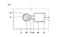
図15は本発明の第8実施形態に係る洗濯機の支持装置を示した斜視図であり、図16は本発明の第8実施形態に係る洗濯機の支持装置を示した断面図であり、図17は図16のV-V線断面図であり、図18は本発明の第8実施形態に係る洗濯機の支持装置を示した作動状態図である。 FIG. 15 is a perspective view illustrating a washing machine support device according to an eighth embodiment of the present invention, and FIG. 16 is a cross-sectional view illustrating the washing machine support device according to an eighth embodiment of the present invention. FIG. 17 is a cross-sectional view taken along the line VV in FIG. 16, and FIG. 18 is an operational state diagram showing the washing machine support device according to the eighth embodiment of the present invention.
第8実施形態に係る洗濯機の支持装置は、ベース10の貫通孔18に上下方向に直線移動可能に挿入される支持レッグ12と、前記支持レッグ12の下端に装着されて底面に接触するフット14と、前記ベース10とフット14との間に装着されてフット14に所定弾性を与えるスプリング16と、前記ベース10の一側に装着されて前記支持レッグ12の上下方向移動をロッキングするロッキングユニット102とを含む。
前記ロッキングユニット102は、前記支持レッグ12に対して直角方向に直線移動可能に配置され、その端が前記支持レッグ12の側面に密着して前記支持レッグ12の長手方向移動をロッキングするプッシュロッド104と、前記プッシュロッド104が直線移動可能に装着され、電源が印加されると前記プッシュロッド104を移動させるアクチュエーター106とを含む。
The washing machine support device according to the eighth embodiment includes a
The
前記ベース10の上面には、前記アクチュエーター106が装着される装着部112が設けられる。
A mounting
前記支持レッグ12の側面には、長手方向にテーパー溝108が形成され、前記プッシュロッド104の端部には、前記テーパー溝108へ挿入するテーパー突起110が形成され、それによりプッシュロッド104と支持レッグ12との間の接触面積が大きくなり、前記支持レッグ12のロッキング作用が円滑に行われる。
A
前記アクチュエーター106は、電源が印加されるとプッシュロッド104を押すソレノイドタイプが適用されるか、電源が印加されると熱膨張しながらプッシュロッドを押すサーモアクチュエーター(thermo-actuator)が適用される。
The
以下、このように構成される第8実施形態に係る洗濯機の支持装置の作用を説明する。
まず、洗濯機を設置場所に配置するとき、底面が不均一である場合には、前記スプリング16の弾性により各支持レッグ12が上下方向に移動しながら洗濯機の均衡を維持し、フット14が不均一な底面に接触した状態を維持する。
Hereinafter, the operation of the washing machine support device according to the eighth embodiment configured as described above will be described.
First, when the washing machine is placed at the installation location, if the bottom surface is uneven, the
このような状態で洗濯機が駆動されると、アクチュエーター106に電源が印加され、プッシュロッド104が直線移動しながら支持レッグ12の側面を加圧する。即ち、支持レッグ12のテーパー溝108にプッシュロッド104のテーパー突起110が嵌合して支持レッグ12の移動をロッキングする。すると、スプリング16の共振が抑制され、スプリング16の共振による振動を低減する。
When the washing machine is driven in this state, power is applied to the
図19は本発明の第9実施形態に係る洗濯機の支持装置を示した断面図であり、図20は図19のVI-VI線断面図である。
第9実施形態に係る洗濯機の支持装置は、第8実施形態の洗濯機の支持装置と同一であるが、ロッキングユニットの構造が異なる。
19 is a cross-sectional view showing a washing machine support device according to a ninth embodiment of the present invention, and FIG. 20 is a cross-sectional view taken along the line VI-VI in FIG.
The washing machine support device according to the ninth embodiment is the same as the washing machine support device of the eighth embodiment, but the structure of the locking unit is different.
前記第9実施形態に係るロッキングユニットは、前記支持レッグ12に対して直角方向に直線移動可能に配置されるプッシュロッド104と、前記プッシュロッド104の端部に一体的に形成されかつ前記支持レッグ16の外周面から所定間隔を置いて配置されるリング120と、前記リング120の内周面に装着されて前記支持レッグ16の外周面に摩擦する摩擦部材122と、前記プッシュロッド104が直線移動可能に装着されかつ電源が印加されると前記プッシュロッド104を直線移動させるアクチュエーター106とを含む。
The locking unit according to the ninth embodiment includes a
このような第9実施形態に係る洗濯機の支持装置は、洗濯機の駆動により前記アクチュエーター106が駆動すると、プッシュロッド104が直線移動することによりリング120が直線移動し、前記リング120の内周面に装着された摩擦部材122が前記支持レッグ12の外周面に密着して前記支持レッグ12の移動をロッキングする。
In the washing machine support device according to the ninth embodiment, when the
10 ベース
12 支持レッグ
14 フット
16 スプリング
18 貫通孔
20 取付けブラケット
22 離脱防止用ナット
24 座部材
DESCRIPTION OF
Claims (25)
前記支持レッグの下端に装着されて底面に接触するフットと、
前記ベースとフットとの間に装着されて前記フットに弾性を与えるスプリングと、
を含むことを特徴とする洗濯機の支持装置。 A plurality of support legs mounted on a base fixed to the lower side of the washing machine main body, at least one of which is vertically movable,
A foot that is attached to the lower end of the support leg and contacts the bottom surface;
A spring that is mounted between the base and the foot and gives elasticity to the foot;
A support device for a washing machine, comprising:
前記ボールが転動自在に挿入される半球状の溝が形成されるとともにフットが装着される支持部材と、
前記支持部材の上側に装着されて前記ボールが支持部材から離脱されることを防止するカバーとを含むことを特徴とする請求項9記載の洗濯機の支持装置。 The joint portion includes a ball formed at an end of a support leg;
A support member on which a foot is mounted while a hemispherical groove into which the ball is rotatably inserted is formed;
The washing machine supporting apparatus according to claim 9, further comprising a cover that is mounted on an upper side of the supporting member and prevents the ball from being detached from the supporting member.
前記支持レッグの下端に装着されて底面に接触するフットと、
前記ベースとフットとの間に装着されて前記フットに弾性を与えるスプリングと、
前記スプリングの上面及びベースの上面に装着されて、洗濯機の駆動時に発生する前記スプリングの共振を抑制して振動を低減する減衰ユニットと、を含むことを特徴とする洗濯機の支持装置。 A number of support legs mounted on the base fixed to the lower side of the washing machine main body so as to be movable in the vertical direction;
A foot that is attached to the lower end of the support leg and contacts the bottom surface;
A spring that is mounted between the base and the foot and gives elasticity to the foot;
A washing machine support device comprising: a damping unit that is mounted on the upper surface of the spring and the upper surface of the base, and that reduces vibration by suppressing resonance of the spring that occurs when the washing machine is driven.
前記ハウジングの内部に配置され、かつ前記支持レッグに締結されて前記支持レッグと共に上下方向に移動してスプリングの下端を支持する第1座部材と、
前記ハウジングの内側上部に設置されて前記スプリングの上端を支持する第2座部材と、
前記第1座部材の外周面に固定されて前記ハウジングの内周面に摩擦する摩擦部材と、を含むことを特徴とする請求項15記載の洗濯機の支持装置。 The damping unit is fastened to the upper surface of the base, and has a housing having a space inside and a through hole through which a support leg passes on the upper side.
A first seat member disposed inside the housing and fastened to the support leg to move up and down together with the support leg to support a lower end of a spring;
A second seat member installed on an inner upper portion of the housing and supporting an upper end of the spring;
The washing machine supporting device according to claim 15, further comprising: a friction member fixed to an outer peripheral surface of the first seat member and frictioning with an inner peripheral surface of the housing.
前記ハウジングの下部に配置されてスプリングの下端を支持する第1座部材と、
前記ハウジングの内側上部に設置されて前記スプリングの上端を支持する第2座部材と、
前記第1座部材の下側に設置され、かつ前記支持レッグに固定されて共に上下方向に移動する支持部材と、
前記支持部材の外周面に固定されて前記ハウジングの内周面に摩擦する摩擦部材と、を含むことを特徴とする請求項15記載の洗濯機の支持装置。 The damping unit is fastened to the upper surface of the base, and has a housing with a space inside and a through-hole through which a support leg passes.
A first seat member disposed at a lower portion of the housing and supporting a lower end of the spring;
A second seat member installed on an inner upper portion of the housing and supporting an upper end of the spring;
A support member installed on the lower side of the first seat member and fixed to the support leg and moving together in the vertical direction;
The washing machine support device according to claim 15, further comprising: a friction member that is fixed to the outer peripheral surface of the support member and rubs against the inner peripheral surface of the housing.
前記支持レッグの下端に装着されて底面に接触するフットと、
前記ベースとフットとの間に装着されて前記フットに弾性を与えるスプリングと、
前記ベースの一側に装着されて、洗濯機の駆動時に前記支持レッグの上下方向移動をロッキングするロッキングユニットと、を含む洗濯機の支持装置。 A number of support legs mounted on the base fixed to the lower side of the washing machine main body so as to be movable in the vertical direction;
A foot that is attached to the lower end of the support leg and contacts the bottom surface;
A spring that is mounted between the base and the foot and gives elasticity to the foot;
A washing machine support device comprising: a locking unit that is mounted on one side of the base and locks the vertical movement of the support leg when the washing machine is driven.
前記プッシュロッドが直線移動可能に装着され、かつ電源が印加されると前記プッシュロッドを移動させるアクチュエーターとを含むことを特徴とする請求項21記載の洗濯機の支持装置。 The locking unit is arranged so as to be linearly movable in a direction perpendicular to the support leg, and a push rod whose end closely contacts a side surface of the support leg and locks the longitudinal movement of the support leg;
The washing machine supporting device according to claim 21, further comprising an actuator that is mounted so that the push rod is linearly movable and that moves the push rod when power is applied.
Applications Claiming Priority (5)
| Application Number | Priority Date | Filing Date | Title |
|---|---|---|---|
| KR1020030085266A KR100739153B1 (en) | 2003-11-27 | 2003-11-27 | Support apparatus with function of self height adjustment and washing machine having the same |
| KR1020030085268A KR100739154B1 (en) | 2003-11-27 | 2003-11-27 | Support apparatus for washing machine and support apparatus with function of self height adjustment |
| KR1020030085267A KR20050051476A (en) | 2003-11-27 | 2003-11-27 | Support apparatus for washing machine and support apparatus with function of self height adjustment |
| KR1020030102278A KR20050069809A (en) | 2003-12-31 | 2003-12-31 | Support apparatus with function of self height adjustment and washing machine having the same |
| KR1020040023490A KR20050098161A (en) | 2004-04-06 | 2004-04-06 | Support apparatus with function of self height adjustment and washing machine having the same |
Publications (2)
| Publication Number | Publication Date |
|---|---|
| JP2005152659A true JP2005152659A (en) | 2005-06-16 |
| JP2005152659A5 JP2005152659A5 (en) | 2008-01-10 |
Family
ID=34624022
Family Applications (1)
| Application Number | Title | Priority Date | Filing Date |
|---|---|---|---|
| JP2004344142A Pending JP2005152659A (en) | 2003-11-27 | 2004-11-29 | Support device of washing machine |
Country Status (3)
| Country | Link |
|---|---|
| US (1) | US7314206B2 (en) |
| JP (1) | JP2005152659A (en) |
| CN (1) | CN100564652C (en) |
Cited By (5)
| Publication number | Priority date | Publication date | Assignee | Title |
|---|---|---|---|---|
| KR100829184B1 (en) * | 2006-10-31 | 2008-05-14 | 삼성전자주식회사 | Washing machine |
| JP2010184004A (en) * | 2009-02-12 | 2010-08-26 | Panasonic Corp | Washing machine |
| JP2019523041A (en) * | 2016-06-30 | 2019-08-22 | 青島海爾洗衣机有限公司QingDao Haier Washing Machine Co.,Ltd. | Automatic leveling washing machine |
| KR20200038627A (en) * | 2018-10-04 | 2020-04-14 | 삼성전자주식회사 | Electronic apparatus |
| WO2022085229A1 (en) * | 2020-10-23 | 2022-04-28 | コクヨ株式会社 | Furniture set-down device and furniture |
Families Citing this family (41)
| Publication number | Priority date | Publication date | Assignee | Title |
|---|---|---|---|---|
| JP4498805B2 (en) * | 2004-04-05 | 2010-07-07 | 株式会社ニフコ | Leg device |
| BRPI0601993A (en) * | 2006-05-11 | 2008-01-08 | Whirlpool Sa | self-leveling foot for an appliance |
| US7673845B2 (en) * | 2006-05-19 | 2010-03-09 | Illinois Tool Works Inc. | Leveling assembly |
| KR101275557B1 (en) * | 2006-07-27 | 2013-06-20 | 엘지전자 주식회사 | Height adjusting structure of washing machine |
| EP1887124A1 (en) * | 2006-08-07 | 2008-02-13 | Electrolux Home Products Corporation N.V. | Floor stabilizing foot for an appliance |
| KR101272341B1 (en) * | 2006-09-19 | 2013-06-05 | 엘지전자 주식회사 | Apparatus and method for sensing vibration of washer |
| DK176705B1 (en) * | 2007-05-03 | 2009-03-23 | Ngi Aps | Procedure and machine shoes |
| DE102007057512A1 (en) * | 2007-11-29 | 2009-06-04 | BSH Bosch und Siemens Hausgeräte GmbH | household appliance |
| KR101466339B1 (en) * | 2008-08-13 | 2014-11-28 | 삼성전자 주식회사 | Washing Machine |
| CH700666A2 (en) * | 2009-03-17 | 2010-09-30 | Digi Sens Digitale Messtech Ag | Apparatus and method for setting up a machine. |
| US8220770B2 (en) | 2009-12-22 | 2012-07-17 | Bsh Home Appliances Corporation | Domestic appliance with height adjustable foot |
| GB2486422B (en) * | 2010-12-13 | 2015-09-09 | Itab Shop Concept Uk Ltd | Shelving unit |
| EP2728050B1 (en) * | 2011-12-08 | 2017-06-28 | Dongbu Daewoo Electronics Corporation | Wall-mounted drum type washing machine |
| US8690272B2 (en) * | 2012-05-22 | 2014-04-08 | Bsh Home Appliances Corporation | Home appliance with support leg cover |
| CN102743037A (en) * | 2012-06-26 | 2012-10-24 | 吴贝尔 | Adjustable supporting leg |
| US9644303B2 (en) * | 2012-09-14 | 2017-05-09 | Dongbu Daewoo Electronics Corporation | Wall-mounted drum washing apparatus |
| JP5601429B1 (en) * | 2014-03-03 | 2014-10-08 | 富士ゼロックス株式会社 | Fixing device, device fixing structure, device fixing method |
| DK178297B1 (en) * | 2014-06-30 | 2015-11-09 | Ngi As | Leveling unit with split spindle and use |
| CN104061409A (en) * | 2014-06-30 | 2014-09-24 | 德阳市尚瑞斯机电设备有限公司 | Damping device for mechanical equipment |
| NZ735099A (en) * | 2015-02-26 | 2022-11-25 | Air Diffusion Agencies Pty Ltd | A mount assembly for engineering services |
| CN106996010B (en) * | 2016-01-22 | 2021-03-02 | 青岛海尔洗衣机有限公司 | Washing machine's automatic levelling device and washing machine |
| CN105755750B (en) * | 2016-04-13 | 2024-04-02 | 青岛海尔洗衣机有限公司 | Washing machine footing and washing machine with automatic leveling function |
| CN105755757B (en) * | 2016-04-13 | 2024-01-12 | 青岛海尔洗衣机有限公司 | Washing machine footing and washing machine with automatic leveling function |
| DE102016118184B3 (en) * | 2016-09-27 | 2017-10-26 | Sartorius Lab Instruments Gmbh & Co. Kg | Use of a hydraulic shock absorber and laboratory device |
| CN108278452B (en) * | 2017-01-06 | 2020-12-22 | 青岛海尔洗衣机有限公司 | Footing for household appliance and household appliance |
| CN106871555B (en) * | 2017-02-14 | 2019-05-28 | 合肥美的电冰箱有限公司 | Levelling foot and refrigerator |
| CN108930870B (en) * | 2017-05-23 | 2021-01-05 | 青岛海尔洗衣机有限公司 | Automatic level adjusting device and laundry treating apparatus including the same |
| US10663175B2 (en) * | 2017-05-30 | 2020-05-26 | Samsung Electronics Co., Ltd. | Home appliance |
| US10716400B2 (en) * | 2017-10-18 | 2020-07-21 | Dell Products, L.P. | System and method for horizontal leveling of server racks |
| CN107956958A (en) * | 2017-12-27 | 2018-04-24 | 贵州大学 | A kind of engineering machinery support device |
| US10779649B2 (en) * | 2018-01-08 | 2020-09-22 | Component Hardware Group, Inc. | Equipment leg |
| US10618076B2 (en) * | 2018-01-10 | 2020-04-14 | Huhtamaki, Inc. | Condiment dispensing device |
| CN108302287B (en) * | 2018-02-01 | 2019-07-05 | 温州市东海建筑安装工程有限公司 | A kind of building machinery Shockproof base |
| CN108789323A (en) * | 2018-06-19 | 2018-11-13 | 郑州搜趣信息技术有限公司 | A kind of computer networking technology service aid case |
| RU2688415C1 (en) * | 2018-10-25 | 2019-05-21 | Владимир Александрович Парамошко | Installation method of washing machine |
| US11925360B2 (en) * | 2018-11-02 | 2024-03-12 | Conmed Corporation | Method for preventing kinked tubing in an arthroscopic irrigation pump |
| CN109506085B (en) * | 2018-12-04 | 2020-12-01 | 苏州经贸职业技术学院 | Mechanical base with buffering shock-absorbing function |
| CN110307446A (en) * | 2019-06-19 | 2019-10-08 | 无锡小天鹅电器有限公司 | Footing device and mechanical equipment |
| CN110742391A (en) * | 2019-11-04 | 2020-02-04 | 泰山学院 | Table leg length adjusting device |
| CN111748970B (en) * | 2020-06-29 | 2022-09-06 | 浙江韦氏电器有限公司 | Shock absorption bracket for height-adjustable washing machine |
| CN114318786B (en) * | 2020-09-29 | 2023-11-28 | 无锡小天鹅电器有限公司 | Foot component and clothes treatment equipment with same |
Family Cites Families (14)
| Publication number | Priority date | Publication date | Assignee | Title |
|---|---|---|---|---|
| US1866274A (en) * | 1930-03-20 | 1932-07-05 | Bell Telephone Labor Inc | Resilient support |
| US2335834A (en) * | 1942-11-26 | 1943-11-30 | Gen Spring Corp | Variable support hanger |
| US2683576A (en) * | 1949-06-14 | 1954-07-13 | Harry G Miller | Hydraulic stabilizing support |
| US2892482A (en) * | 1956-05-21 | 1959-06-30 | Joseph J Beoletto | Vehicle seat mounting units |
| US3191895A (en) * | 1963-03-06 | 1965-06-29 | Gen Motors Corp | Platform stabilizer |
| US4798359A (en) * | 1983-07-14 | 1989-01-17 | Johnson Industries, Inc. | Furniture glide |
| US4949923A (en) * | 1989-07-18 | 1990-08-21 | Maytag Corporation | Self-leveling assembly for an appliance |
| DE3942334A1 (en) | 1989-12-21 | 1991-06-27 | Basf Ag | METHOD FOR PROCESSING HYDROXYLAMMONIUM AND AMMONIUM SALTS CONTAINING AQUEOUS NUTS |
| JP3287585B2 (en) | 1991-05-02 | 2002-06-04 | カヤバ工業株式会社 | Electromagnetic friction damper |
| JPH0584387A (en) | 1991-09-27 | 1993-04-06 | Matsushita Electric Ind Co Ltd | Drum type washing machine |
| DE4138961A1 (en) * | 1991-11-27 | 1993-06-03 | Ymos Ag Ind Produkte | MACHINE FOOT |
| US5967472A (en) * | 1997-04-03 | 1999-10-19 | Bsh Bosch Und Siemens Hausgeraete Gmbh | Height-adjusting device for an adjusting foot of a household appliance |
| KR100268282B1 (en) | 1997-12-19 | 2000-10-16 | 윤종용 | Rest leg of a washing machine |
| JP3789312B2 (en) * | 2001-03-29 | 2006-06-21 | 株式会社ニックス | Adjustable feet for equipment |
-
2004
- 2004-11-18 US US10/990,553 patent/US7314206B2/en not_active Expired - Fee Related
- 2004-11-25 CN CNB200410096246XA patent/CN100564652C/en not_active Expired - Fee Related
- 2004-11-29 JP JP2004344142A patent/JP2005152659A/en active Pending
Cited By (6)
| Publication number | Priority date | Publication date | Assignee | Title |
|---|---|---|---|---|
| KR100829184B1 (en) * | 2006-10-31 | 2008-05-14 | 삼성전자주식회사 | Washing machine |
| JP2010184004A (en) * | 2009-02-12 | 2010-08-26 | Panasonic Corp | Washing machine |
| JP2019523041A (en) * | 2016-06-30 | 2019-08-22 | 青島海爾洗衣机有限公司QingDao Haier Washing Machine Co.,Ltd. | Automatic leveling washing machine |
| KR20200038627A (en) * | 2018-10-04 | 2020-04-14 | 삼성전자주식회사 | Electronic apparatus |
| KR102587256B1 (en) * | 2018-10-04 | 2023-10-11 | 삼성전자주식회사 | Electronic apparatus |
| WO2022085229A1 (en) * | 2020-10-23 | 2022-04-28 | コクヨ株式会社 | Furniture set-down device and furniture |
Also Published As
| Publication number | Publication date |
|---|---|
| CN100564652C (en) | 2009-12-02 |
| US20050116134A1 (en) | 2005-06-02 |
| US7314206B2 (en) | 2008-01-01 |
| CN1621600A (en) | 2005-06-01 |
Similar Documents
| Publication | Publication Date | Title |
|---|---|---|
| JP2005152659A (en) | Support device of washing machine | |
| KR101466339B1 (en) | Washing Machine | |
| US20060075791A1 (en) | Washing machine | |
| US7204104B2 (en) | Damper of drum type washing machine | |
| JP2005344705A (en) | Compressor supporting device | |
| JP2010524806A (en) | Vibration isolator for sliding rail guide | |
| KR101837928B1 (en) | Damping apparatus for communication system | |
| KR100268282B1 (en) | Rest leg of a washing machine | |
| KR101202260B1 (en) | Wheel Assembly of Moving Robot having Single Vertical Shaft | |
| JP5003461B2 (en) | Washing machine | |
| KR101377150B1 (en) | washing machine | |
| KR101048092B1 (en) | Damper for Drum Washing Machine | |
| KR101772082B1 (en) | Leg assembly of washing machine | |
| KR100739154B1 (en) | Support apparatus for washing machine and support apparatus with function of self height adjustment | |
| JP2007229219A (en) | Drum type washing machine | |
| KR100442935B1 (en) | A vibrationless leg for washing machine | |
| KR100608672B1 (en) | Compressor support apparatus for refrigerator | |
| KR101770815B1 (en) | Leg for washing machine | |
| KR101033559B1 (en) | leg assembly for home appliance | |
| KR100739153B1 (en) | Support apparatus with function of self height adjustment and washing machine having the same | |
| KR101008622B1 (en) | leg assembly for home appliance | |
| KR970000281Y1 (en) | Belt tension control apparatus for drum washing machine | |
| KR20050051476A (en) | Support apparatus for washing machine and support apparatus with function of self height adjustment | |
| KR20050069809A (en) | Support apparatus with function of self height adjustment and washing machine having the same | |
| KR20080065433A (en) | Device of supporting compressor |
Legal Events
| Date | Code | Title | Description |
|---|---|---|---|
| A521 | Written amendment |
Free format text: JAPANESE INTERMEDIATE CODE: A523 Effective date: 20071119 |
|
| A621 | Written request for application examination |
Free format text: JAPANESE INTERMEDIATE CODE: A621 Effective date: 20071119 |
|
| A977 | Report on retrieval |
Free format text: JAPANESE INTERMEDIATE CODE: A971007 Effective date: 20090703 |
|
| A131 | Notification of reasons for refusal |
Free format text: JAPANESE INTERMEDIATE CODE: A131 Effective date: 20090714 |
|
| A521 | Written amendment |
Free format text: JAPANESE INTERMEDIATE CODE: A523 Effective date: 20091009 |
|
| A02 | Decision of refusal |
Free format text: JAPANESE INTERMEDIATE CODE: A02 Effective date: 20091222 |