CN109506085B - Mechanical base with buffering shock-absorbing function - Google Patents
Mechanical base with buffering shock-absorbing function Download PDFInfo
- Publication number
- CN109506085B CN109506085B CN201811476556.2A CN201811476556A CN109506085B CN 109506085 B CN109506085 B CN 109506085B CN 201811476556 A CN201811476556 A CN 201811476556A CN 109506085 B CN109506085 B CN 109506085B
- Authority
- CN
- China
- Prior art keywords
- base
- sliding
- buffering
- mounting plate
- rod
- Prior art date
- Legal status (The legal status is an assumption and is not a legal conclusion. Google has not performed a legal analysis and makes no representation as to the accuracy of the status listed.)
- Active
Links
Images


Classifications
-
- F—MECHANICAL ENGINEERING; LIGHTING; HEATING; WEAPONS; BLASTING
- F16—ENGINEERING ELEMENTS AND UNITS; GENERAL MEASURES FOR PRODUCING AND MAINTAINING EFFECTIVE FUNCTIONING OF MACHINES OR INSTALLATIONS; THERMAL INSULATION IN GENERAL
- F16M—FRAMES, CASINGS OR BEDS OF ENGINES, MACHINES OR APPARATUS, NOT SPECIFIC TO ENGINES, MACHINES OR APPARATUS PROVIDED FOR ELSEWHERE; STANDS; SUPPORTS
- F16M5/00—Engine beds, i.e. means for supporting engines or machines on foundations
-
- F—MECHANICAL ENGINEERING; LIGHTING; HEATING; WEAPONS; BLASTING
- F16—ENGINEERING ELEMENTS AND UNITS; GENERAL MEASURES FOR PRODUCING AND MAINTAINING EFFECTIVE FUNCTIONING OF MACHINES OR INSTALLATIONS; THERMAL INSULATION IN GENERAL
- F16F—SPRINGS; SHOCK-ABSORBERS; MEANS FOR DAMPING VIBRATION
- F16F7/00—Vibration-dampers; Shock-absorbers
Abstract
The invention discloses a mechanical base with a buffering and damping function, which comprises a base, an installation plate, a plurality of buffering devices and a locking device, wherein the buffering devices and the locking device are uniformly arranged between the base and the installation plate; the buffer device comprises a sliding cylinder, a sliding rod, a limiting rod and a spring, wherein the upper end of the sliding cylinder is fixed on the lower end surface of the base, the lower part of the sliding cylinder is connected with the upper part of the sliding rod in a sliding manner, the lower end of the sliding rod is fixedly arranged on the mounting plate, the spring which is arranged at the lower end of the sliding cylinder in a compressing manner is sleeved on the sliding rod, and the upper end and the lower end of the limiting rod are respectively fixedly connected on the base; the anti-loosening device comprises a pressing plate for pressing and fixing a screw to prevent the screw from loosening, and solves the problems that the buffering and anti-shock capacity is poor, the deformation is easy to generate, the screw is easy to loosen, and the machining size precision is easy to reduce in the prior art; the invention has good buffering and damping effects, reduces the deformation of the base, has high machining size precision and avoids the phenomenon that a screw is easy to loosen during machining.
Description
Technical Field
The invention relates to the technical field of mechanical bases, in particular to a mechanical base with a buffering and damping function.
Background
With the continuous progress of mechanical production technology, the mechanical base is very commonly applied to the current mechanical production and processing equipment, especially to the forming and processing mechanical equipment, but most of the mechanical bases on the market have certain defects.
When processing machinery equipment is carrying out the product and is forming man-hour, mechanical base can produce intermittent type nature or the removal and the vibrations of persistence, but the buffering shock resistance of current mechanical base itself is relatively poor, and mechanical base bears the gravity of processing machinery equipment and the long time this can produce certain degree of deformation in the past of the vibrations impact that produces when the machine operation, and the screw of mechanical base fixed mounting department is not hard up easily moreover, can lead to processing machinery equipment's processing size precision to descend, influences product processingquality.
In order to solve the above problems, the present invention provides a mechanical base with a buffering and shock absorbing function.
Disclosure of Invention
The invention aims to provide a mechanical base with a buffering and damping function, which can greatly reduce the deformation of the mechanical base, prevent a fixing screw from loosening and ensure the stability and the processing precision of the mechanical base.
In order to achieve the purpose, the mechanical base with the buffering and shock absorbing functions comprises a base and is characterized by further comprising a mounting plate arranged at the lower part of the base, a plurality of buffering devices uniformly and vertically arranged between the base and the mounting plate, and a locking device arranged on the mounting plate; the buffer device comprises a sliding cylinder, a sliding rod, a limiting rod and a spring, wherein the upper end of the sliding cylinder is fixed on the lower end surface of the base, the lower part of the sliding cylinder is connected with the upper part of the sliding rod in a sliding manner, the lower end of the sliding rod is fixedly arranged on the mounting plate, the spring arranged at the lower end of the sliding cylinder in a compressing manner is sleeved on the sliding rod, and the upper end and the lower end of the limiting rod are respectively fixedly connected on the base and the mounting plate; the anti-loosening device comprises a pressing plate for pressing and fixing the screw to prevent the screw from loosening.
Preferably, a plurality of evenly distributed mounting grooves are formed in the upper end of the mounting plate, and the lower ends of the sliding rod, the limiting rod and the spring on the buffering device are fixedly mounted in the mounting grooves.
Preferably, the slide bar is inserted into a slide cavity formed in the bottom of the slide cylinder.
Preferably, the bottom of the sliding cylinder is fixedly sleeved with a sleeve disc, the sleeve disc is provided with two through holes which are symmetrically distributed, and the two limiting rods respectively penetrate through the through holes.
Preferably, the upper end of the spring is fixedly connected with the sleeve disc.
Preferably, locking device still includes articulated seat, kelly and the lantern ring, articulated seat with the one end of clamp plate is articulated just articulated seat has the torsional spring with the junction fixed mounting of clamp plate, the other end pressfitting of clamp plate is on fixing screw, the kelly is fixed on the mounting panel, just the cover has on the kelly is used for injecing the clamp plate is the lantern ring of not pressfitting set screw state.
Preferably, the two sides of the mounting plate are fixedly connected with symmetrically distributed fixing seats, the fixing seats are provided with threaded holes, the threaded holes are provided with fixing screws, and the two side surfaces of the mounting plate are fixed with the anti-loosening devices; the hinged seat and the clamping rod are fixedly arranged on two sides of the mounting plate.
Preferably, the bottom of the mounting plate is provided with a plurality of anti-skid grains which are uniformly distributed.
The mechanical base with the buffering and damping functions provided by the invention has the following beneficial effects:
1. the damping effect is achieved on the base through the buffer device, the slight displacement generated by the base is absorbed, the condition that the base bears the load for a long time and is deformed due to vibration is reduced, the factors causing the reduction of the machining size precision are reduced, and the stability can be improved through the limiting rod, so that the stability of the mechanical base and the machining precision of the whole machining mechanical equipment are guaranteed.
2. Will the lantern ring is followed the kelly is taken off, thereby articulated seat with the clamp plate junction fixed mounting the torsional spring makes the clamp plate rotates the pressfitting downwards on the screw, avoided the removal of base intermittent type nature or continuity and vibrations make the not hard up phenomenon appears in the screw.
Drawings
FIG. 1 is a schematic structural diagram of a mechanical base with buffering and shock absorbing functions according to the present invention;
FIG. 2 is a schematic view of the anti-loosening device shown in FIG. 1 in a pressed state;
FIG. 3 is an enlarged view of a portion of FIG. 1 at A;
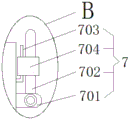
FIG. 4 is an enlarged view of a portion of FIG. 1 at B;
in the figure:
1. the mounting plate 2, the base 3, the fixed seat 4, the screw 5, the mounting groove 6, the buffer device 601, the sliding barrel 602, the sleeve disc 603, the sliding rod 604, the limiting rod 605, the spring 7, the anti-loosening device 701, the hinge seat 702, the pressing plate 703, the clamping rod 704 and the sleeve ring.
Detailed Description
As shown in fig. 1 to 4, a mechanical base with buffering and shock absorbing functions comprises a base 2, and is characterized by further comprising a mounting plate 1 arranged at the lower part of the base 2, a plurality of buffering devices 6 uniformly and vertically arranged between the base 2 and the mounting plate 1, and a locking device 7 arranged on the mounting plate 1; the buffer device 6 comprises a sliding cylinder 601, a sliding rod 603, a limiting rod 604 and a spring 605, wherein the upper end of the sliding cylinder 601 is fixed on the lower end surface of the base 2, the lower part of the sliding cylinder 601 is slidably connected with the upper part of the sliding rod 603, the lower end of the sliding rod 603 is fixedly arranged on the mounting plate 1, the spring 605 which is arranged at the lower end of the sliding cylinder 601 in a compressed manner is sleeved on the sliding rod 603, and the upper end and the lower end of the limiting rod 604 are respectively fixedly connected on the base 2 and the mounting plate 1; the anti-loosening device 7 comprises a pressing plate 702 for pressing the fixing screw 4 to prevent the screw 4 from loosening. A plurality of evenly distributed's antiskid line has been seted up to the bottom of mounting panel 1, has reduced the phenomenon that mounting panel 1 takes place to sideslip.
As shown in fig. 1 to 3, the upper end of the mounting plate 1 is provided with a plurality of mounting grooves 5 which are uniformly distributed, and the lower ends of the sliding rod 603, the limiting rod 604 and the spring 605 on the buffering device 6 are fixedly mounted in the mounting grooves 5, so that the mechanical base has better stability. The slide bar 603 is inserted into a slide cavity formed in the bottom of the slide cylinder 601. The bottom of the sliding cylinder 601 is also fixedly sleeved with a sleeve disc 602, the sleeve disc 602 is provided with two through holes which are symmetrically distributed, the two limiting rods 604 respectively penetrate through the through holes, and the stability of the sleeve disc 602 during sliding down can be improved through the limiting rods 604. The upper end of the spring 605 is fixedly connected with the sleeve disc 602, so that the buffer device 6 is prevented from deviating in the process of absorbing the vibration of the base, and the stability is good.
Various processing mechanical equipment are arranged on the base 2, when the base 2 is intermittently or continuously moved or vibrated during product forming and processing, slight relative offset can be generated between the base 2 and the mounting plate 1 to drive the sliding cylinder 601 to slide along the sliding rod 603, so that the sleeve disc 602 on the sliding cylinder 601 compresses or extends the spring 605, the effect of buffering and damping is achieved on the base 2, the slight displacement generated by the base 2 is absorbed, the deformation condition caused by long-term bearing and vibration bearing of the base 2 is reduced, and the factors causing the reduction of the processing size precision are reduced.
As shown in fig. 1, 2 and 4, the anti-loosening device 7 further includes a hinge seat 701, a clamping rod 703 and a collar 704, the hinge seat 701 is hinged to one end of the pressing plate 702, a torsion spring is fixedly installed at a joint of the hinge seat 701 and the pressing plate 702, the other end of the pressing plate 702 is pressed on the fixing screw 4, the clamping rod 703 is L-shaped and fixed on the mounting plate 1, and the collar 704 for limiting the pressing plate 702 to be in a state of not pressing on the fixing screw 4 is sleeved on the clamping rod 703. Fixing seats 3 which are symmetrically distributed are fixedly connected to two sides of the mounting plate 1, threaded holes are formed in the fixing seats 3, fixing screws 4 are mounted on the threaded holes, and the anti-loosening devices 7 are fixed to two side faces of the mounting plate 1; the hinge seat 701 and the clamping rod 703 are fixedly arranged on two sides of the mounting plate 1.
As shown in fig. 1, 2 and 4, the clamping rod 703 and the pressing plate 702 are sleeved with each other by the collar 704, when the mounting plate 1 is fixed, the mounting plate 1 is fixedly mounted in the mounting area by the screw 4, and then the collar 704 is taken down from the clamping rod 703, so that the torsion spring fixedly mounted at the joint of the hinge seat 701 and the pressing plate 702 makes the pressing plate 702 rotate downwards and press-fit on the screw 4, and the phenomenon that the screw 4 is loosened due to intermittent or continuous movement and vibration of the base 2 is avoided.
The invention solves the problems that the mechanical base in the prior art has poor buffering and shock resistance and is easy to deform, and the screw at the fixed mounting position of the mechanical base is easy to loosen, so that the processing dimensional precision of processing mechanical equipment is easy to reduce; the buffer device 6 has the effects of buffering and damping the base, reduces the deformation condition of the base 2 caused by long-term bearing and vibration bearing, reduces the factors causing the reduction of the machining size precision, can also improve the stability through the limiting rod 604, and presses the screw 4 through the pressing plate 702, thereby avoiding the phenomenon that the screw is loosened due to intermittent or continuous movement and vibration of the base easily caused during machining, and further ensuring the stability of the mechanical base and the machining precision of the whole machining machinery.
In the description of the present invention, it should be noted that the terms "center", "upper", "lower", "left", "right", "vertical", "horizontal", "inner", "outer", etc., indicate orientations or positional relationships based on the orientations or positional relationships shown in the drawings, and are only for convenience of description and simplicity of description, but do not indicate or imply that the device or element being referred to must have a particular orientation, be constructed and operated in a particular orientation, and thus, should not be construed as limiting the present invention.
The inventive concept is explained in detail herein using specific examples, which are given only to aid in understanding the core concepts of the invention. It should be understood that any obvious modifications, equivalents and other improvements made by those skilled in the art without departing from the spirit of the present invention are included in the scope of the present invention.
Claims (6)
1. A mechanical base with buffering and shock absorbing functions comprises a base and is characterized by also comprising a mounting plate arranged at the lower part of the base, a plurality of buffering devices uniformly and vertically arranged between the base and the mounting plate, and a locking device arranged on the mounting plate;
the buffer device comprises a sliding barrel, a sliding rod, two limiting rods, a spring and a sleeve disc, wherein the upper end of the sliding barrel is fixed on the lower end surface of the base, the lower part of the sliding barrel is connected with the upper part of the sliding rod in a sliding manner, the lower end of the sliding rod is fixedly arranged on the mounting plate, the spring which is arranged at the lower end of the sliding barrel in a compressing manner is sleeved on the sliding rod, the two limiting rods are respectively arranged at two sides of the sliding barrel, and the upper end and the lower end of each limiting rod are respectively fixedly connected on the base and the mounting plate; the bottom of the sliding cylinder is also fixedly sleeved with a sleeve disc, the sleeve disc is provided with two through holes which are symmetrically distributed, and the two limiting rods respectively penetrate through the through holes;
the anti-loosening device comprises a pressing plate for pressing and fixing the screw to prevent the screw from loosening;
the locking device is characterized by further comprising a hinged seat, a clamping rod and a sleeve ring, wherein the hinged seat is hinged to one end of the pressing plate, a torsion spring is fixedly arranged at the joint of the hinged seat and the pressing plate, the other end of the pressing plate is pressed on the fixing screw, the clamping rod is fixed on the mounting plate, and the clamping rod is sleeved with the sleeve ring which is used for limiting the pressing plate to be in a non-pressing fixing screw state.
2. The mechanical base with the buffering and shock-absorbing functions as claimed in claim 1, wherein the upper end of the mounting plate is provided with a plurality of mounting grooves which are uniformly distributed, and the lower ends of the sliding rod, the limiting rod and the spring on the buffering device are fixedly mounted in the mounting grooves.
3. The mechanical base with the buffering and shock-absorbing functions as claimed in claim 2, wherein the sliding rod is inserted into a sliding cavity formed at the bottom of the sliding cylinder.
4. The mechanical base with the functions of buffering and damping as claimed in claim 3, wherein the upper end of the spring is fixedly connected with the sleeve disc.
5. The mechanical base with the buffering and shock absorbing functions as claimed in claim 1, wherein fixing seats are fixedly connected to two sides of the mounting plate, the fixing seats are symmetrically distributed, threaded holes are formed in the fixing seats, fixing screws are mounted on the threaded holes, and the anti-loosening devices are fixed to two side faces of the mounting plate; the hinged seat and the clamping rod are fixedly arranged on two sides of the mounting plate.
6. The mechanical base with the buffering and shock-absorbing functions as claimed in claim 1, wherein the bottom of the mounting plate is provided with a plurality of anti-skid lines which are uniformly distributed.
Priority Applications (1)
| Application Number | Priority Date | Filing Date | Title |
|---|---|---|---|
| CN201811476556.2A CN109506085B (en) | 2018-12-04 | 2018-12-04 | Mechanical base with buffering shock-absorbing function |
Applications Claiming Priority (1)
| Application Number | Priority Date | Filing Date | Title |
|---|---|---|---|
| CN201811476556.2A CN109506085B (en) | 2018-12-04 | 2018-12-04 | Mechanical base with buffering shock-absorbing function |
Publications (2)
| Publication Number | Publication Date |
|---|---|
| CN109506085A CN109506085A (en) | 2019-03-22 |
| CN109506085B true CN109506085B (en) | 2020-12-01 |
Family
ID=65751609
Family Applications (1)
| Application Number | Title | Priority Date | Filing Date |
|---|---|---|---|
| CN201811476556.2A Active CN109506085B (en) | 2018-12-04 | 2018-12-04 | Mechanical base with buffering shock-absorbing function |
Country Status (1)
| Country | Link |
|---|---|
| CN (1) | CN109506085B (en) |
Families Citing this family (3)
| Publication number | Priority date | Publication date | Assignee | Title |
|---|---|---|---|---|
| CN111322338A (en) * | 2019-09-02 | 2020-06-23 | 西安长东船舶动力有限公司 | Double-damping device of power generation equipment control box and power generation system |
| CN110779211B (en) * | 2019-11-13 | 2021-08-17 | 江苏浴普太阳能有限公司 | Damping fixing frame of air energy water heater |
| CN114370387A (en) * | 2020-10-15 | 2022-04-19 | 常熟向洋电气科技有限公司 | Vacuum pump that radiating effect is good |
Family Cites Families (7)
| Publication number | Priority date | Publication date | Assignee | Title |
|---|---|---|---|---|
| US7314206B2 (en) * | 2003-11-27 | 2008-01-01 | Lg Electronics Inc. | Supporting apparatus for washing machine |
| JP2012017836A (en) * | 2010-07-09 | 2012-01-26 | Daihatsu Diesel Mfg Co Ltd | Vibration isolation method of diesel engine |
| CN106825686B (en) * | 2017-03-01 | 2019-02-19 | 浙江海澄德畅机械有限公司 | A kind of adjustable machine components punch device of damping effect |
| CN207302798U (en) * | 2017-10-24 | 2018-05-01 | 江西明正变电设备有限公司 | A kind of amorphous alloy dry-type transformer of new structure |
| CN207661317U (en) * | 2017-12-19 | 2018-07-27 | 广州广彩标签有限公司 | A kind of stable type printing banding machine |
| CN207880318U (en) * | 2018-02-10 | 2018-09-18 | 广州益邦能源科技有限公司 | A kind of screw pump damping base |
| CN108518524A (en) * | 2018-06-13 | 2018-09-11 | 中山达鼎精密工业有限公司 | A kind of valve limit switch with blast resistance construction |
-
2018
- 2018-12-04 CN CN201811476556.2A patent/CN109506085B/en active Active
Also Published As
| Publication number | Publication date |
|---|---|
| CN109506085A (en) | 2019-03-22 |
Similar Documents
| Publication | Publication Date | Title |
|---|---|---|
| CN109506085B (en) | Mechanical base with buffering shock-absorbing function | |
| CN209793535U (en) | Stable supporting device of stamping die | |
| CN105058083A (en) | Multi-wedge-face sliding type clamping mechanism | |
| CN204553498U (en) | A kind of intelligentized Furniture mounting nuts | |
| CN210817028U (en) | Precision stamping die with buffer structure | |
| CN107234033B (en) | Micro-concave scraper clamping plate adjusting mechanism | |
| CN207629559U (en) | Screw knife assembly | |
| CN111922930A (en) | Firm dysmorphism machine parts centre gripping equipment | |
| CN104776107A (en) | Mounting nut for intelligent furniture | |
| CN111059209A (en) | Supporting base for hardware mould production and processing | |
| CN214348919U (en) | Damping base for stamping equipment for outer shell of air conditioner | |
| CN211728930U (en) | Electronic device connecting jig | |
| CN212095359U (en) | Machine part production and processing is with spacing fixing device of general type | |
| CN212857402U (en) | Circular arc bending die | |
| CN207858318U (en) | Aluminium section bar processing buffer pressing positioner | |
| CN211318745U (en) | Distance sensor and electronic terminal with same | |
| CN107825124A (en) | Screwdriver suspension member | |
| CN211564235U (en) | Stamping die clamping device | |
| CN209050144U (en) | Device is transformed in mold diameter of bore | |
| CN208644662U (en) | A kind of lathe-used hydraulic buffering plate | |
| CN105345497B (en) | Linkage type floating clamp | |
| CN212240233U (en) | Damping device of machine tool | |
| CN209987660U (en) | Noise reduction device of mould engraving machine | |
| CN213225138U (en) | Drilling tool for pin hole of plate spring lifting lug support | |
| CN218224676U (en) | Piston rod finish turning shockproof tool |
Legal Events
| Date | Code | Title | Description |
|---|---|---|---|
| PB01 | Publication | ||
| PB01 | Publication | ||
| SE01 | Entry into force of request for substantive examination | ||
| SE01 | Entry into force of request for substantive examination | ||
| GR01 | Patent grant | ||
| GR01 | Patent grant |