JP2005152123A - Game machine - Google Patents
Game machine Download PDFInfo
- Publication number
- JP2005152123A JP2005152123A JP2003392606A JP2003392606A JP2005152123A JP 2005152123 A JP2005152123 A JP 2005152123A JP 2003392606 A JP2003392606 A JP 2003392606A JP 2003392606 A JP2003392606 A JP 2003392606A JP 2005152123 A JP2005152123 A JP 2005152123A
- Authority
- JP
- Japan
- Prior art keywords
- reel
- distance
- detection member
- reels
- symbol
- Prior art date
- Legal status (The legal status is an assumption and is not a legal conclusion. Google has not performed a legal analysis and makes no representation as to the accuracy of the status listed.)
- Pending
Links
Images


Landscapes
- Slot Machines And Peripheral Devices (AREA)
Abstract
Description
本発明は、例えば、パチンコやスロットマシンにおけるリールの図柄認識に用いて好適な遊技機に関する。 The present invention relates to a gaming machine suitable for use in, for example, reel symbol recognition in a pachinko or slot machine.
スロットマシンには、通常、本体部前面に3列のリール有するリール機構が組み込まれ、これらリールの側方(右側壁面)に、いわゆる演出表示を行うための表示装置としての表示パネルが設けられている。
かかる構成において、遊技者により回転開始ノブが押下されると、ゲーム開始となり、3列のリールを所定速度で回転させ、次に停止釦が押下されると、リールを順次停止させる。そして、停止した3個のリールに描かれている特定の絵柄(例えば、数字の7)が入賞ライン上に揃うと「大当り」となり、表示パネルに大当たり表示を行うことによって遊技者に通知し快感を与えるようにしている。
In a slot machine, a reel mechanism having three rows of reels is usually incorporated on the front surface of the main body, and a display panel as a display device for performing so-called effect display is provided on the side (right wall surface) of these reels. Yes.
In such a configuration, when the rotation start knob is pressed by the player, the game starts, and the reels of the three rows are rotated at a predetermined speed, and when the stop button is pressed next, the reels are sequentially stopped. When a specific pattern (for example, the number 7) drawn on the three stopped reels is aligned on the winning line, it becomes a “hit”, and the player is notified by displaying the jackpot on the display panel. Like to give.
ところで、上記したリールの図柄を認識するために、従来、リールの回転基準位置に認識用の突起等、物理的なイニシャルを設け、その位置を原点にステッピングモータによるステップ数をカウントすることにより認識していた。
また、図柄のそれぞれにイニシャルを設け、図柄位置を認識する技術も知られている(例えば、特許文献1、2、3)。
By the way, in order to recognize the above-described reel design, conventionally, a physical initial such as a recognition protrusion is provided at the rotation reference position of the reel, and the number of steps by the stepping motor is counted from that position as the origin. Was.
In addition, a technique for providing an initial for each symbol and recognizing the symbol position is also known (for example, Patent Documents 1, 2, and 3).
しかしながら、前記した背景技術によれば、ソレノイドに基づく外乱ノイズ等により遊技機に内蔵されたメモリ内容が消滅し、あるいは破壊されることがあり誤動作することがある。また、ステッピングモータが脱調等した場合、遊技機は、現在どの図柄を表示しているのか不明となる。
この場合、イニシャルを再度検出する必要があった。このため、回胴の起動時間に悪影響を与え遊技者に不快感を与え、また、誤った表示をしてしまい、更にはステッピングモータが脱調しないように回転制御および回転動作に制約がかかってしまうといった問題があった。
However, according to the background art described above, the contents of the memory built in the gaming machine may be lost or destroyed due to disturbance noise or the like based on the solenoid, which may cause malfunction. Further, when the stepping motor is out of step, etc., the gaming machine becomes unclear which symbol is currently displayed.
In this case, it was necessary to detect the initial again. This adversely affects the start-up time of the rotating drum, causing the player to feel uncomfortable, causes incorrect display, and restricts rotation control and rotation operation so that the stepping motor does not step out. There was a problem such as.
本発明は上記事情に鑑みてなされたものであり、絵柄単位で位置情報を取得可能な構成とすることで、回胴の起動時間の短縮をはかり、また、絵柄を認識する際の信頼性を高め、多彩な演出を可能とした遊技機を提供することを目的とする。 The present invention has been made in view of the above circumstances, and by adopting a configuration in which position information can be acquired on a pattern basis, the start-up time of the rotating drum is shortened, and the reliability when recognizing the pattern is improved. The purpose is to provide a gaming machine that can enhance and produce various effects.
上記した課題を解決するために本発明は、複数種類の識別情報が設けられたリールを有する可変表示装置を備えた遊技機であって、前記リールの内側面に形成され、前記絵柄毎距離差を検知できる範囲の傾斜を持つ前記リールと共に回転する検出部材と、前記検出部材と対抗する側面位置に取り付けられ、前記検出部材との距離を計測して図柄単位で位置情報を取得する位置情報取得手段と、を備えたことを特徴とする。 In order to solve the above-described problems, the present invention is a gaming machine including a variable display device having a reel provided with a plurality of types of identification information, and is formed on an inner surface of the reel, and the difference in distance between the pictures. Position information acquisition that is attached to a detection member that rotates together with the reel having an inclination within a range in which the detection can be detected, and a side surface position that opposes the detection member, and that measures the distance from the detection member and acquires position information in symbol units. Means.
また、本発明において、前記検出部材は、前記リールとは別体で前記リールに比較して回転半径の小さな検出部材であることを特徴とする。 In the present invention, the detection member may be a detection member that is separate from the reel and has a smaller radius of rotation than the reel.
また、本発明において、前記位置情報取得手段は、前記検出部材に対して出射される基準投光信号と前記検出部材から反射される受講信号との位相差により距離を演算してそのデータを出力することを特徴とする。 In the present invention, the position information acquisition means calculates a distance based on a phase difference between a reference projection signal emitted to the detection member and a attendance signal reflected from the detection member, and outputs the data. It is characterized by doing.
本発明によれば、リールの内側面に形成され、絵柄毎距離差を検知できる範囲の傾斜を持つ検出部材との距離を、距離センサを用いて計測することで、図柄単位でその位置情報を取得することができ、このことにより、回胴の起動時間の短縮がはかれ、多彩な演出が可能となる。
更に、傾斜を持つ検出部材を、リールに比較して回転半径の小さな部材で構成することにより、回転ブレによる影響を抑えることができる。更に、傾斜を持つ検出部材との距離を計測して絵柄を認識することで、ステップモータによるステップ数のカウントを不要とし絵柄認識の際の信頼性が向上する。
According to the present invention, the distance information is measured by using a distance sensor, and the position information is obtained in units of symbols. As a result, the start-up time of the rotating drum can be shortened, and various effects can be achieved.
Furthermore, by configuring the detection member having an inclination with a member having a smaller rotation radius than that of the reel, it is possible to suppress the influence of the rotation blur. Furthermore, by measuring the distance from the detecting member having an inclination and recognizing the pattern, counting of the number of steps by the step motor is unnecessary, and the reliability at the time of pattern recognition is improved.
以下、本発明の好適な実施形態として、遊戯場等に設置される回胴式遊技機(以下「スロットマシン」という)について、図1ないし図15を参照しながら詳細説明を行う。 Hereinafter, as a preferred embodiment of the present invention, a spinning machine (hereinafter referred to as “slot machine”) installed in an amusement hall or the like will be described in detail with reference to FIGS.
図1は、本スロットマシン100の外部構造を表した平面図、図2は、本スロットマシン100の内部構造を表した平面図である。
図1において、本スロットマシン100は、遊技者に面するフロントドア101と、フロントドア101が開閉可能に取り付けられた箱形形状の筐体102とを備えて構成されている。
フロントドア101は、基本的に、金属製のフレーム(図示略)に硬質プラスチック等で成形された前面パネルが取り付けられた機械的に強固な構造を有し、当該前面パネルによって、上部パネル部103と中部パネル部104と下部パネル部105が構成されている。
FIG. 1 is a plan view showing the external structure of the
In FIG. 1, the
The
上部パネル部103には、演出用ランプ103aと、スピーカが取り付けられた放音部103b,103cと、液晶ディスプレイ等で形成された演出表示用の表示装置103dが設けられている。
中部パネル部104には、複数個(本実施形態では3個)のリールR1,R2,R3を備えたリール装置200が略中央の位置に設けられている。また、リール装置200の前面に、透明な硬質プラスチック板で形成された略長方形の透過窓WDが取り付けられ、これによってリール装置200を外部から保護すると共に、遊技者が透過窓WDを介してリールR1,R2,R3を見ることが可能となっている。更に、透過窓WDの周縁には額縁状の縁部WPが一体形成されており、当該縁部WPがいわゆる化粧板の機能とスロットマシン100の前面を密封する機能を備えている。
The
The
中部パネル部104の下端には、遊技者が操作するための操作部104aが備えられ、遊技用メダルを投入するためのメダル投入部MDが備え付けられている。また、操作部104aの操作面上に、1ゲーム当たりのメダル数を提示するためのベットボタンBET(B1,B2,B3)が設けられ、更にその前面には、1ゲームの開始を指示するためのスタートレバーSTと、回転中のリールR1,R2,R3を個別に停止させるための3個のストップボタンSP1,SP2,SP3が設けられている。
なお、このうち、ストップボタンSP1,SP2,SP3は、リールR1,R2,R3の位置にそれぞれ対応付けて配置されるものとする。
At the lower end of the
Of these, the stop buttons SP1, SP2, and SP3 are arranged in association with the positions of the reels R1, R2, and R3, respectively.
下部パネル部105には、本スロットマシン100のゲーム内容に関連した画像等(図示略)が描かれており、遊技者の獲得したメダルを払い出すための排出口105a及び受皿105bと、スピーカが設けられた放音部105cが設けられている。
An image (not shown) related to the game contents of the
次に、図2を参照して、フロントドア101の裏面構造と、筐体102の内部構造を説明する。図2はフロントドア101を開錠して筐体102から開いた状態を表している。
同図において、フロントドア101の裏面上部に、放音部103b,103cを構成するスピーカSR,SLが設けられ、スピーカSR,SLの間に表示装置103dが設けられている。
Next, the back surface structure of the
In the figure, speakers SR and SL constituting
更に、リール装置200下部には、メダル投入部MDより投入される投入物を正規の遊技用メダルか異物か判別して振り分ける振分機構G0と、振分機構G0で振り分けられた遊技用メダルを筐体102側に設けられているホッパ装置HPへ案内するガイド部材G1と、振分機構G0で振り分けられた異物を排出口105aへ案内して排出するガイド部材G2と、ホッパ装置HPから出力される払い出し用のメダルを排出口105aへ案内して出力するガイド部材G3が設けられ、更に排出口105aの近傍に、スピーカSWが放音部105cに対応させて取り付けられている。
Furthermore, at the lower part of the
筐体102内には、主電源装置PWUと、ホッパ装置HPから溢れた遊技用メダルを収容するための補助貯留部SHPと、フロントドア101側の透過窓WDに対向するリールR1,R2,R3を備えたリール装置200と、本スロットマシン100の動作全体を集中制御する電気回路基板等を備えた主制御ユニット400が設けられている。
In the
筐体102内には、主電源装置PWUと、ホッパ装置HPから溢れた遊技用メダルを収容するための補助貯留部SHPと、フロントドア101側の透過窓WDに対向するリールR1,R2,R3を備えたリール装置200と、本スロットマシン100の動作全体を集中制御する電気回路基板等を備えた主制御ユニット400が設けられている。
In the
ここで、主制御ユニット400は、図3のブロック図に示すように、スロットマシン100の動作全体を管理するシステムプログラム及びスロットマシンゲーム用の実行プログラムが予め記憶されている半導体メモリ等で形成された記憶部と、これらのプログラムを実行する図示せぬマイクロプロセッサとを有するメイン制御基板400aを備える。
また、メイン制御基板400aが搭載されている電気回路基板とは夫々別個の電気回路基板で形成され、メイン制御基板400aからの指令に従って分散制御を行うサブ制御基板400bおよびリール制御部400c、そして入力ポート400d、入出力ポート400g、400hを備えて構成されている。
Here, as shown in the block diagram of FIG. 3, the
Also, the
上記した構成において、遊技者が操作部104aに配置されたベットボタンBET(B1,B2,B3)およびスタートレバーSTを操作することにより遊技が開始され、適当なタイミングでストップボタンSP1,SP2,SP3(300)を順次操作することにより、大当たり抽選が開始される。これら操作内容は入力ポート400dを介して取り込まれ、また、メイン制御基板400aによって抽選を含む大当たり抽選処理が実行され、その結果は、メイン制御基板400aによる制御の下、接続されるLED、ランプ等の表示デバイスの駆動、あるいは点灯制御を行う。
In the above-described configuration, the game is started when the player operates the bet buttons BET (B1, B2, B3) and the start lever ST disposed on the
また、振分機構GOとホッパ装置HPは、入出力ポート400g,400hを介してメイン制御基板400aに接続され、制御される。更に、サブ制御基板400bは、音響制御部400iと、照明制御部400jおよび表示装置制御部400kを備え、音響制御部400iにはスピーカSL,SR,SWが、照明制御部400jには演出用ランプ103a,104a,104bが接続されている。
The distribution mechanism GO and the hopper device HP are connected to and controlled by the main control board 400a via the input /
そして、ゲームの進行等に応じてメイン制御基板400aから指令される演出制御の内容に従って、音響制御部400iはスピーカSL,SR,SWによる音響演出の制御、照明制御部400jは演出用ランプ103a,104a,104bによる照明演出の制御を行う。
また、リール制御部400cは、リール装置200に設けられている電動モータ(図示略)を制御し、リールR1,R2,R3の回転と制動及び停止の制御を行う。以下、リール装置200の内部構成について詳細説明を行う。
Then, according to the contents of the effect control commanded from the main control board 400a according to the progress of the game, etc., the
The
図4に、リール装置200の斜視図、図5に、リールの外周面に配置された図柄の一例が示されている。
ここでは、3列のリールR1,R2,R3が備え付けられ、各リールに、「7」、「チェリー」、「りんご」、「スター」等の図柄が配置され、遊技者の停止操作に基づき、所定の図柄を3列表示して乱数抽選により遊技の入賞態様に応じた特定の図柄組み合わせが停止制御される。なお、図柄のそれぞれには、“00”〜“20”の図柄番号が付与され認識される。
FIG. 4 shows a perspective view of the
Here, three rows of reels R1, R2, and R3 are provided, and symbols such as “7”, “Cherry”, “Apple”, and “Star” are arranged on each reel, and based on the player's stop operation, A predetermined symbol combination corresponding to the winning mode of the game is controlled to stop by a random number lottery by displaying three predetermined symbols. Each symbol is assigned a symbol number “00” to “20” for recognition.
図6にリール装置200に実装されるリールの一実施形態が示されている。ここではリールR1の側面図が示されている。
図6中、符号61はリール、符号62はボス、符号63は本発明の構成要件であるリール61と一体形成される枠板(検出部材)である。枠板63は、リール61の内側面に一体で、もしくは着脱自在に形成され、絵柄毎それぞれ対応する位置に段差a〜nが設けられ、リール61と共に回転する。
FIG. 6 shows an embodiment of a reel mounted on the
In FIG. 6,
図7にリールの他の実施形態が示されている。ここでは、枠板63はリール61の内側面に一体で、もしくは着脱自在に形成され、図6に示す例と異なり段差を持たず、スロープ状に形成されている。
図7中、符号64は距離センサである。距離センサ64は、枠板63に対して出射される基準投光信号と枠板63から反射される受光信号との位相差により距離を演算してそのデータを出力する赤外線によるセンサを想定している。
FIG. 7 shows another embodiment of the reel. Here, the
In FIG. 7,
図8に距離センサ64の配置の一例が示されている。ここでは、リール平面が示されており、枠板63と対抗する側面位置に取り付けられ、スロープ状に形成された枠板63との距離を計測し、図柄単位でその位置情報を取得するものである。
なお、図6に示すリール61に距離センサ64は図示省略されているが、図8同様、同じ位置に配置されており、段差が形成された枠板63との距離を計測する。
FIG. 8 shows an example of the arrangement of the
Although the
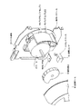
図9にリール装置200の分解斜視図が示されている。ここでは、リール61と一体形成される枠板63として、図8に示すスロープ形状の枠板63が例示されている。
図9に示されるように、枠板63を含むリール61の中にボス62が実装され、更に、リール基板60上にアセンブルされる。なお、リール基板60上には、モータ67、およびバックランプアセンブリ69が実装され、図示せぬ距離センサがセンサベース上に実装配置される。
An exploded perspective view of the
As shown in FIG. 9, a
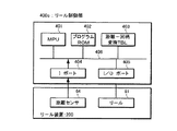
図13は、リール制御部400cの内部構成を示すブロック図である。リール制御部400cは、MPU401(マイコン)を核に、プログラムROM402、RAM403、入力(I)ポート404、入出力(I/O)ポート405が、アドレス、データ、コントロールのためのラインが複数本で構成されるシステムバス406に共通接続されて成る。
RAM403には、距離−図柄変換テーブルが記憶されており、図14にそのデータ構造の一例が示されるように、図柄No.毎、距離センサ64から出力される距離データとの対応が示されている。
FIG. 13 is a block diagram showing an internal configuration of the
The
入力ポート404には距離センサ64が、入出力ポート405にはリール61が接続される。MPU401は、プログラムROM402に記録されたプログラムを読み出して逐次実行することにより、距離センサ64を介して枠板63と距離センサ64設置位置間の距離を取込み、RAM403に割付けられた距離−図柄変換TBLを参照して図柄No.を取得し、PU401経由でメイン基板400aへ供給する。
A
図15に、図柄変換のための処理手順がフローチャートで示されている。図15に示すフローチャートにおいて、MPU401は、まず、リール装置200に実装される距離センサ64からIポート404を介して距離データ(アナログ信号)を取り込み(S151)、取込まれた距離値dが規定の範囲にあるか否かをチェックし(S152)、ここで規定の範囲にあればS153の処理に進む。ここでは、リール61が正常動作しているか否かをチェックしており、リール61が暴走しない限りS153の処理に進む。
次に、MPU401は、RAM403に割付けられた距離−図柄変換TBL403を参照し(S153)、先に取り込んだ距離データに基づき、対応する図柄No.を索引する(S154)。ここで、ヒットした場合(距離値dが定義範囲にある)、対応する図柄番号をメイン基板400aへ出力し(S155)、ヒットしなかった場合はS151の処理に戻り、以降の手順を繰り返す。このようにして1絵柄毎、対応する絵柄No.をメイン基板400aへ供給し、現在表示絵柄の認識を促す。
FIG. 15 is a flowchart showing a processing procedure for symbol conversion. In the flowchart shown in FIG. 15, the
Next, the
図10に、リール装置200の他の実施形態について分解斜視図が示されている。図中、図6、図7に示すリール61の実施形態と同一番号が付された部材は、図6、7に示すそれと同じである。
ここで、検出部材63は、図6、図7に示す実施形態とは異なり、リール61とは別体に形成され、モータ67の軸方向と垂直に配置し、かつ、回転半径が小となっている。このことにより軸ブレによる影響を最小限に抑えている。
なお、図10において、符号60はリール基板、符号65はセンサベース、符号66はセンサ台、符号67は、リール61および検出部材63を回転駆動するモータ、符号68はモータベース、符号69はバックランプアセンブリ、符号70はバックランプLEDである。
FIG. 10 is an exploded perspective view of another embodiment of the
Here, unlike the embodiment shown in FIGS. 6 and 7, the
In FIG. 10,
図11は、リール装置200の更に他の実施形態を示す図であり、(a)に正面図、(b)に分解平面図を示す。
図中、図10と同一番号が付された部材は、図10に示すそれと同じである。ここでは、図10に示す実施形態に、更に、モータ軸のスラスト方向に対して距離変位する図柄検知手段とし、回転ムラによる距離計測の誤差の最小化をはかっている。
なお、図11中、符号71はボス穴である。
FIGS. 11A and 11B are views showing still another embodiment of the
In the figure, members denoted by the same reference numerals as those in FIG. 10 are the same as those shown in FIG. Here, in addition to the embodiment shown in FIG. 10, symbol detection means that displaces the distance relative to the thrust direction of the motor shaft is used to minimize distance measurement errors due to rotation unevenness.
In FIG. 11,
図12は、イナーシャの偏りによる回転ブレを防ぐために示したモータ駆動系の構成を示す図であり、(a)に平面図を、(b)に断面図を示す。
図12(a)(b)に示されるように、リール61の外周部にはギヤ611が刻まれてあり、モータ67軸に嵌合されたギア612と、更に中間ギア613を介して動力が伝わる構造になっている。
遊技機は、距離センサから与えられた距離データによって瞬時にどの絵柄を表示しているか認識することができ、更に、従来のようにモータ67が直接リール61を駆動する構造に比較して回転トルクが少なく済みイナーシャの偏りを受けにくく、リール装置200の脱調等を未然に防ぐことができる。
FIGS. 12A and 12B are diagrams showing the configuration of a motor drive system shown to prevent rotational blur due to bias of inertia, where FIG. 12A is a plan view and FIG.
As shown in FIGS. 12A and 12B, a
The gaming machine can recognize which picture is displayed instantaneously based on the distance data given from the distance sensor, and further, the rotational torque compared to the structure in which the
以上説明のように本発明によれば、リールの内側面に一体形成され、絵柄毎距離差を検知できる範囲の傾斜を持つ検出部材との距離を、距離センサを用いて計測することで、図柄単位でその位置情報を取得することができ、このことにより、回胴の起動時間の短縮がはかれ、多彩な演出が可能となる。また、段差を設ける方法に比べ、絵柄数を任意に設定できるといった派生的効果も生じる。
更に、傾斜を持つ検出部材を、リールに比較して回転半径の小さな部材で構成することにより、回転ブレによる影響を抑えることができる。更に、検出部材との距離を計測することによって絵柄を認識することで、ステップモータによるステップ数のカウントを不要とし絵柄認識の際の信頼性が向上する。
なお、上記した実施形態によれば、スロットマシンの図柄検出のみ例示して説明したが、他にパチンコの図柄検出に用いても同様の効果が得られる。
As described above, according to the present invention, the distance between the detection member and the detection member that is integrally formed on the inner side surface of the reel and has a slope that can detect the distance difference between the patterns is measured by using the distance sensor. The position information can be acquired in units of units, which shortens the start-up time of the rotating drum and enables various effects. In addition, there is a derivative effect that the number of patterns can be arbitrarily set as compared with the method of providing a step.
Furthermore, by configuring the detection member having an inclination with a member having a smaller rotation radius than that of the reel, it is possible to suppress the influence of the rotation blur. Furthermore, by recognizing the pattern by measuring the distance from the detection member, counting of the number of steps by the step motor is unnecessary, and the reliability at the time of pattern recognition is improved.
In addition, according to the above-described embodiment, only the symbol detection of the slot machine has been illustrated and described. However, the same effect can be obtained even when used for the symbol detection of the pachinko.
60 リール基板
61 リール
62 ボス
63 検出部材(枠板)
64 距離センサ
65 センサベース
66 センサ台
67 モータ
68 モータベース
69 バックウンプアセンブリ
70 バックランプLED
200 リール装置
400a メイン基板
400c リール制御部
401 MPU
403 RAM(距離−図柄変換TBL)
60
64 Distance sensor 65
200 reel device 400a main board
400c
403 RAM (distance-design conversion TBL)
Claims (3)
前記リールの内側面に形成され、前記絵柄毎距離差を検知できる範囲の傾斜を持つ前記リールと共に回転する検出部材と、
前記検出部材と対抗する側面位置に取り付けられ、前記検出部材との距離を計測して図柄単位で位置情報を取得する位置情報取得手段と、
を備えたことを特徴とする遊技機。 A gaming machine including a variable display device having a reel provided with a plurality of types of identification information,
A detection member that is formed on the inner surface of the reel and rotates together with the reel having an inclination in a range in which the distance difference between the patterns can be detected;
Position information acquisition means that is attached to a side surface position that opposes the detection member, measures the distance to the detection member, and acquires position information in symbol units;
A gaming machine characterized by comprising:
前記検出部材に対して出射される基準投光信号と前記検出部材から反射される受講信号との位相差により距離を演算してそのデータを出力することを特徴とする請求項1または2に記載の遊技機。 The position information acquisition means includes
The distance is calculated from the phase difference between the reference projection signal emitted to the detection member and the attendance signal reflected from the detection member, and the data is output. Game machines.
Priority Applications (1)
| Application Number | Priority Date | Filing Date | Title |
|---|---|---|---|
| JP2003392606A JP2005152123A (en) | 2003-11-21 | 2003-11-21 | Game machine |
Applications Claiming Priority (1)
| Application Number | Priority Date | Filing Date | Title |
|---|---|---|---|
| JP2003392606A JP2005152123A (en) | 2003-11-21 | 2003-11-21 | Game machine |
Publications (1)
| Publication Number | Publication Date |
|---|---|
| JP2005152123A true JP2005152123A (en) | 2005-06-16 |
Family
ID=34719252
Family Applications (1)
| Application Number | Title | Priority Date | Filing Date |
|---|---|---|---|
| JP2003392606A Pending JP2005152123A (en) | 2003-11-21 | 2003-11-21 | Game machine |
Country Status (1)
| Country | Link |
|---|---|
| JP (1) | JP2005152123A (en) |
Cited By (1)
| Publication number | Priority date | Publication date | Assignee | Title |
|---|---|---|---|---|
| US8758129B2 (en) | 2010-10-06 | 2014-06-24 | Aristocrat Technologies Australia Pty Limited | Gaming system and method of gaming in which symbol reels selectively rotate in less than a full rotation |
Citations (5)
| Publication number | Priority date | Publication date | Assignee | Title |
|---|---|---|---|---|
| JPH06265370A (en) * | 1993-03-11 | 1994-09-20 | Mitsubishi Electric Corp | Optical rotation-angle detection apparatus |
| JPH06319297A (en) * | 1994-04-19 | 1994-11-15 | Universal Hanbai Kk | Rotating position detecting device for stepping motor |
| JPH08327400A (en) * | 1995-05-29 | 1996-12-13 | Fujitsu Ltd | Measuring instrument for amount of rotation |
| JP2001183172A (en) * | 1999-12-24 | 2001-07-06 | Tdk Corp | Position or angle detecting apparatus |
| JP2003310819A (en) * | 2002-04-26 | 2003-11-05 | Samii Kk | Reel unit |
-
2003
- 2003-11-21 JP JP2003392606A patent/JP2005152123A/en active Pending
Patent Citations (5)
| Publication number | Priority date | Publication date | Assignee | Title |
|---|---|---|---|---|
| JPH06265370A (en) * | 1993-03-11 | 1994-09-20 | Mitsubishi Electric Corp | Optical rotation-angle detection apparatus |
| JPH06319297A (en) * | 1994-04-19 | 1994-11-15 | Universal Hanbai Kk | Rotating position detecting device for stepping motor |
| JPH08327400A (en) * | 1995-05-29 | 1996-12-13 | Fujitsu Ltd | Measuring instrument for amount of rotation |
| JP2001183172A (en) * | 1999-12-24 | 2001-07-06 | Tdk Corp | Position or angle detecting apparatus |
| JP2003310819A (en) * | 2002-04-26 | 2003-11-05 | Samii Kk | Reel unit |
Cited By (1)
| Publication number | Priority date | Publication date | Assignee | Title |
|---|---|---|---|---|
| US8758129B2 (en) | 2010-10-06 | 2014-06-24 | Aristocrat Technologies Australia Pty Limited | Gaming system and method of gaming in which symbol reels selectively rotate in less than a full rotation |
Similar Documents
| Publication | Publication Date | Title |
|---|---|---|
| JP5158946B2 (en) | Game machine | |
| JP2006280607A (en) | Slot machine | |
| JP2007061465A (en) | Rotary drum type game machine | |
| JP4974337B2 (en) | Reel device for gaming machine | |
| JP2008073298A (en) | Game machine | |
| JP2014193198A (en) | Game machine | |
| JP2007143729A (en) | Game machine | |
| JP2005152126A (en) | Game machine | |
| JP2005102830A (en) | Game machine | |
| JP2005152122A (en) | Game machine | |
| JP2005152123A (en) | Game machine | |
| JP2007159626A (en) | Game machine | |
| JP2005152124A (en) | Game machine | |
| JP2005152125A (en) | Game machine | |
| JP2007195680A (en) | Pattern display device and game machine carrying it | |
| JP2007307191A (en) | Game machine | |
| JP2005073796A (en) | Game machine | |
| JP2014193199A (en) | Game machine | |
| JP4632233B2 (en) | Game machine | |
| JP2006081827A (en) | Slot machine | |
| JP2007014547A (en) | Game machine | |
| JP2006068240A (en) | Game machine | |
| JP2007097609A (en) | Slot machine | |
| JP5851447B2 (en) | Game machine | |
| JP2012170790A (en) | Game machine |
Legal Events
| Date | Code | Title | Description |
|---|---|---|---|
| A621 | Written request for application examination |
Free format text: JAPANESE INTERMEDIATE CODE: A621 Effective date: 20061113 |
|
| A131 | Notification of reasons for refusal |
Free format text: JAPANESE INTERMEDIATE CODE: A131 Effective date: 20091208 |
|
| A977 | Report on retrieval |
Free format text: JAPANESE INTERMEDIATE CODE: A971007 Effective date: 20091209 |
|
| A02 | Decision of refusal |
Free format text: JAPANESE INTERMEDIATE CODE: A02 Effective date: 20100402 |