JP2005132632A - Locking device - Google Patents
Locking device Download PDFInfo
- Publication number
- JP2005132632A JP2005132632A JP2004311853A JP2004311853A JP2005132632A JP 2005132632 A JP2005132632 A JP 2005132632A JP 2004311853 A JP2004311853 A JP 2004311853A JP 2004311853 A JP2004311853 A JP 2004311853A JP 2005132632 A JP2005132632 A JP 2005132632A
- Authority
- JP
- Japan
- Prior art keywords
- spring
- rod
- locking device
- load
- outer ring
- Prior art date
- Legal status (The legal status is an assumption and is not a legal conclusion. Google has not performed a legal analysis and makes no representation as to the accuracy of the status listed.)
- Pending
Links
Images


Classifications
-
- F—MECHANICAL ENGINEERING; LIGHTING; HEATING; WEAPONS; BLASTING
- F15—FLUID-PRESSURE ACTUATORS; HYDRAULICS OR PNEUMATICS IN GENERAL
- F15B—SYSTEMS ACTING BY MEANS OF FLUIDS IN GENERAL; FLUID-PRESSURE ACTUATORS, e.g. SERVOMOTORS; DETAILS OF FLUID-PRESSURE SYSTEMS, NOT OTHERWISE PROVIDED FOR
- F15B15/00—Fluid-actuated devices for displacing a member from one position to another; Gearing associated therewith
- F15B15/20—Other details, e.g. assembly with regulating devices
- F15B15/26—Locking mechanisms
- F15B15/262—Locking mechanisms using friction, e.g. brake pads
Abstract
Description
本発明は、負荷がかかったロッドをロッド外周に作用する少なくとも1個のクランプ部材によってクランプするためのロック装置であって、前記クランプ部材がその外周が円錐状に形成されるとともに、前記クランプ部材の円錐形状に対応する円錐状内周を有するアウターリング内をスライド可能であり、前記クランプ部材がロッドによって負荷方向に連れ動かされる際にロッドに対して自己増幅的に押し付けるロック装置に関する。 The present invention is a locking device for clamping a loaded rod with at least one clamping member acting on the outer periphery of the rod, wherein the outer periphery of the clamping member is formed in a conical shape, and the clamping member The present invention relates to a locking device that is slidable in an outer ring having a conical inner circumference corresponding to the conical shape of the above-mentioned, and that presses against the rod in a self-amplifying manner when the clamp member is moved in the load direction by the rod.
この種の締付けロック装置は、例えば昇降台、支えシリンダ、劇場の二重舞台などに使用される。またこの種のロック装置は工作機械または荷役機器の垂直軸用の落下防止装置としても適用される。
ふつうロック装置は油圧または空気圧によって解除ポジションに保たれて、圧力降下時に機能することとなる。その際、下降する荷重エネルギ(負荷)がクランプ力の発生に利用される。つまり、下降しようとする負荷そのものがクランプ力を増強するという、自己増幅的なロックメカニズムが用いられているのである。
This type of tightening lock device is used in, for example, a lifting platform, a support cylinder, and a double stage in a theater. This type of locking device is also applied as a fall prevention device for the vertical axis of machine tools or cargo handling equipment.
Usually, the locking device is kept in the release position by hydraulic pressure or air pressure, and functions when the pressure drops. At that time, the descending load energy (load) is used to generate the clamping force. In other words, a self-amplifying locking mechanism is used in which the load to be lowered itself increases the clamping force.
上記技術分野の段落で述べた構成を備えたロック装置は特許文献1から、公知であり、このロック装置では、クランプ部材は作動開始にあたりロッドによって負荷方向に連れ動きされ、その際、クランプ部材の円錐状の外周輪郭がロッドに自己増幅的に付着摩擦力を発生させる。クランプ部材はこの場合、−定格負荷が大幅に上回らないかぎり−、ハウジングに固定されたストッパに当たることはない。それゆえ、過負荷は塑性変形によるロック装置の破壊を導くことがある。こうした事情からその使用可能性は過負荷が生じないようなケースに限定されることとなる。それゆえこのロック装置は特に落下物体の運動エネルギを散逸させるには不適であり、締付けロッドをブロックするが、制動目的には適していない。
確かに理論的には、ストッパが、クランプ部材の軸方向変位に対して、それを上回るとスリップが生ずるまさしく一定の締付け力を生み出すようにして各部品を製造することが考えられるが、実際のところ、達成可能な製作誤差条件下でこれを保証することは不可能である。
A locking device having the configuration described in the paragraph of the technical field is known from
Certainly, theoretically, it is conceivable to manufacture each part so that the stopper generates a very constant tightening force that causes slipping when the stopper exceeds the axial displacement of the clamp member. However, it is impossible to guarantee this under the achievable manufacturing error conditions.
上記実状に鑑み、本発明の課題は、保持力を正確に制限するとともに、過負荷時にロック装置が損傷を蒙ることなく、特に重要な部品が塑性変形を受けることなしに、ロッドに計画通りのスリップを生じさせるロック装置を提供することである。本発明のさらなる課題は、過大な製作誤差の要求をすることなしに、低いコストで製作可能とすることである。 In view of the above situation, the object of the present invention is to accurately limit the holding force, to prevent the locking device from being damaged in the event of an overload, and to prevent the rod from undergoing plastic deformation, and to prevent the rod from undergoing plastic deformation. It is to provide a locking device that causes slip. A further object of the present invention is to enable production at a low cost without requiring excessive production errors.
前記課題を解決するため、負荷がかかったロッドをロッド外周に作用する少なくとも1個のクランプ部材によってクランプするためのロック装置において、本発明では、前記クランプ部材がその外周が円錐状に形成されるとともに、前記クランプ部材の円錐形状に対応する円錐状内周を有するアウターリング内をスライド可能であり、前記クランプ部材がロッドによって負荷方向に連れ動かされる際にロッドに対して自己増幅的に押し付けるものであり、前記アウターリングはハウジング内を軸方向にスライド可能であるとともに第1バネにより負荷方向に対向するように初期付勢され、前記ロッドに生ずる負荷が前もって設定された負荷を超えた場合に初めて前記アウターリングがスライド変位するように前記第1バネの初期付勢力が設定されている。 In order to solve the above-mentioned problem, in the locking device for clamping a loaded rod with at least one clamping member acting on the outer periphery of the rod, in the present invention, the outer periphery of the clamping member is formed in a conical shape. In addition, it is slidable in an outer ring having a conical inner circumference corresponding to the conical shape of the clamp member, and presses the rod in a self-amplifying manner when the clamp member is moved in the load direction by the rod. The outer ring is slidable in the axial direction in the housing and is initially biased by the first spring so as to oppose the load direction, and the load generated on the rod exceeds a preset load. The initial biasing force of the first spring is set so that the outer ring slides for the first time. It has been.
この構成により、以下の作用が生ずることとなる。
作動開始に際し、前もって設定された負荷、−一般に定格負荷とも呼ばれる−、に達するまでロッドはクランプ部材を連れ動かすが、ただしこの段階でのクランプ部材の軸方向スライド変位は何らかのストッパによって止められることはない。負荷が所定の負荷値を超えると初めてクランプ部材は初期付勢されているアウターリングを連れ動かし、クランプ部材が最終的にストッパによりそれ以上の軸方向スライド変位が阻止されるまで第1バネを圧縮する。したがって、初期付勢力を付与する第1バネは非常に正確に定めることのできる最大保持力を発生させることができ、この最大保持力を超える負荷が作用することでロッドがスリップし始める。
With this configuration, the following effects are produced.
At the start of operation, the rod moves the clamping member until it reaches a preset load, commonly referred to as the rated load, but the axial sliding displacement of the clamping member at this stage is not stopped by any stopper. Absent. Only when the load exceeds a predetermined load value does the clamp member move the initially biased outer ring and compresses the first spring until the clamp member is finally prevented from further axial sliding displacement by the stopper. To do. Therefore, the first spring that applies the initial urging force can generate a maximum holding force that can be determined very accurately, and the rod starts to slip when a load exceeding this maximum holding force is applied.
当業者にはクランプ部材の構成に関して多種の態様が知られている。このクランプ部材はその作用領域に1本もしくは複数本の軸方向スリットを有する円錐形ブシュであるのが好適である。ただし、円周方向に並列配置された複数個のクランプ部材を作用させる方法も排除されているわけではない。 Various aspects of the construction of the clamping member are known to those skilled in the art. The clamping member is preferably a conical bush having one or more axial slits in its working area. However, a method of operating a plurality of clamp members arranged in parallel in the circumferential direction is not excluded.
クランプ部材を外囲するアウターリングは閉じたリングとして形成されているのが好適であるが、これは複数の部材から構成することも可能であり、その場合には、発生する径方向力をくい止めるための対策が講じられなければならない。 The outer ring surrounding the clamping member is preferably formed as a closed ring, but it can also be composed of a plurality of members, in which case the generated radial force is blocked. Measures must be taken.
前もって設定された値を上回る負荷が生じた後に初めてクランプ部材が軸方向においてストッパに突き当たるようにするには、アウターリングに作用する第1バネの初期付勢力を、前もって設定された負荷(定格負荷)を受け止めるのに要される値よりも僅かに高く選択するのが好ましい。またさらに、第1バネがバネ変位してアウターリングの軸方向スライド変位がこの第1バネをまだそのブロックポジションにまで押し込まないように第1バネのバネ変位量が選択され、むしろ第1バネは、クランプ部材の軸方向スライド変位が完了したときに、所定の力をアウターリングにおよぼし、その結果所定保持力ないし制動力がロッドに発生するようにすることが必要である。 In order for the clamp member to abut against the stopper in the axial direction for the first time after a load exceeding a preset value occurs, the initial biasing force of the first spring acting on the outer ring is set to a preset load (rated load). It is preferable to choose a value slightly higher than the value required to receive. Furthermore, the amount of spring displacement of the first spring is selected so that the first spring is displaced and the axial sliding displacement of the outer ring does not push the first spring to its block position yet. When the axial sliding displacement of the clamp member is completed, it is necessary to apply a predetermined force to the outer ring so that a predetermined holding force or braking force is generated on the rod.
原理的にはクランプ部材をストッパに直接接当させる構造も可能であるが、コンパクトな構造の趣旨からして、クランプ部材の緩めを実施する緩めピストンを介在させるのが好ましい。 In principle, a structure in which the clamp member is in direct contact with the stopper is possible, but it is preferable that a loose piston for loosening the clamp member is interposed for the purpose of a compact structure.
さらに、クランプ部材を外囲するアウターリングは無負荷状態においてのみならず、負荷時にあっても緩めピストンないしストッパから離間して位置させ、他方、クランプ部材は緩めピストンに常に接した状態に保たれている構成が好適である。後者の状態はクランプ部材が通例第2のバネによって締付け方向に付勢されていることによって実現される。 Furthermore, the outer ring that surrounds the clamp member is not only in a no-load state, but also is loosened and positioned away from the piston or stopper even when loaded, while the clamp member is loosened and kept in constant contact with the piston. The configuration is suitable. The latter state is realized by the fact that the clamping member is normally biased in the tightening direction by a second spring.
さらに好適な構成の1つは、第1バネはハウジングに固定されたストッパとしてのストッパリングにバネ受け支持され、このストッパリングは同時にポジションにおいてピストンのストローク移動を制限するものであり、この場合ストッパリングが緩めピストンの緩めポジションを定めていることになる。
本発明によるその他の特徴及び利点は、以下図面を用いた実施形態の説明により明らかになるだろう。
In a further preferred configuration, the first spring is supported by a stopper ring as a stopper fixed to the housing, and this stopper ring simultaneously restricts the stroke movement of the piston in the position. The ring is loosened and the piston is loosened.
Other features and advantages of the present invention will become apparent from the following description of embodiments using the drawings.
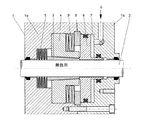
図1、2、3は、本発明の1つの実施形態における異なる作用状態を示しており、このロック装置では、軸方向に隣接した2個のハウジング部材1aと1bとからなる円筒形のハウジング1はその中心をロッド2が貫通している。ハウジング1は不図示の方法で固定取付けされており、他方、ロッド2は変位可能な機械要素であって、このロック装置によってロック可能となる。そのためロッド2は円錐状のクランプ部材3によって外囲されており、このクランプ部材3は本実施形態において外周が円錐状に形成されたブシュの形態を採用している。このクランプ部材3は公知のように軸方向スリットを有しており、そのため径方向に弾性を有している。クランプ部材3は後に詳しく説明するアウターリング4の内周面に嵌め込まれ、軸方向において皿バネセットとして構成された第2バネ5によってロック方向(ロッド2に締め付け作用を及ぼす方向)に付勢されている。クランプ部材3は第2バネ5とは反対側の端部において緩めピストン6に接当しており、このピストン6自体はハウジング部材1b内に軸方向スライド可能にガイドされている。緩めピストン6はクランプ部材3とは反対側の端面側にハウジング部材1bとともにシリンダチャンバ7を形成している。このシリンダチャンバ7にはハウジング孔を経て圧媒手段 、−圧縮空気または圧媒油−、を作用させることができるため、このチャンバ7の圧力によってクランプ部材3をそのロックポジションから左方へ緩めポジションまで変位させることができる。緩めピストン6のストローク移動は緩めポジションにおけるストッパリング8との接当によって制限される。このストッパリング8は2個のハウジング部材1aと1bとの間の連結部に形成された溝に嵌合し、したがって軸方向不動に固定されている。
1, 2 and 3 show different working states in one embodiment of the present invention. In this locking device, a
ここで重要な点は、前述したアウターリング4はハウジング部材1a内で軸方向スライド可能に案内され、第1バネ9、−好ましくは皿ばねセットから構成される−、によって負荷方向とは反対方向に、したがってクランプ部材3を締め付けるように初期付勢されていることである。第1バネ9はアウターリング4の段差部としての環状切欠き内に配置され、アウターリング4とは反対側の端面で前述したストッパリング8にバネ受け支持されている。第1バネ9の初期付勢力はロッド2にこのロック装置の定格負荷を上回る負荷が生じた場合に初めてバネ変位するように選択されている。これにより以下に述べるような機能が生ずる。
The important point here is that the
通常運転においてロッド2はこのロック装置内をいずれの方向にも通過可能となっている。そのためシリンダチャンバ7には圧媒手段が作用し、緩めピストン6は外周面が円錐形状のクランプ部材3をこれに作用する第2バネ5の付勢力に抗して左方の緩めポジションに変位させ、同所に保持している。図1はこの状態を示したものである。
In normal operation, the
ロッド2をクランプ部材3が締め付けるロック状態はシリンダチャンバ7内の圧力が開放されることによって開始される。これによって第2ばね5はクランプ部材3を右方へ変位させることができ、その際、このスライド変位運動はロッド2の運動によって助けられるが、その結果公知の自己増幅的な締め付け作用が導かれる。
The locked state in which the
ロッド2に生ずる負荷が定格負荷以下にあるかぎり、第1バネ9はアウターリング4を左方のストップポジションに保持し、他方、クランプ部材3はロッド2によって負荷方向に連れ動きされる。図2はこの状態を示したものである。
As long as the load generated on the
ロッド2に生ずる負荷が定格負荷を超えると、第1バネ9はもはやアウターリング4を左方のストップポジションに保持することはできない。かくてアウターリング4はクランプ部材3をこのクランプ部材3が接当している緩めピストン6とともに右方へ変位させることになり、緩めピストン6および結果的にはクランプ部材3をハウジング1bに当て付けることになる。図3はこの状態を示したものである。
When the load generated on the
ロッド2に生ずる負荷がさらに増大すると、スリップが生ずる。ただしこのスリップは、公知のロック装置とは異なり、正確に定まった制動力にて行なわれる。この制動力は第1バネ9のバネ力、クランプ部材3とアウターリング4との間の円錐(コーン)角および摩擦係数によって与えられるが、ロッド2に生ずる負荷には依存していない。
When the load generated on the
図4は、負荷−ロッド移動量の関係を線図で示したものである。先ず、定格負荷に達するまで保持力は直線的に増加することがみとめられる。特性線のこの部分はアウターリング4に対するクランプ部材3の相対変位と、それによって生ずる締め付け力の自己増幅的な作用に基づいている。
定格負荷に達するかまたは定格負荷に達した直後に第1バネ9が作用する。したがって特性線は屈曲して、図3に示したようにクランプ部材3が緩めピストン6を介してハウジング1に突き当たるまで、ほぼフラットな線を描くことになる。負荷がさらに増大すると最終的にロック装置の保持力を上回ることになりスリップが生ずるが、その際、保持力ないし制動力は第1バネ9の強度によって定められる。この場合、制動力は本発明により運動体荷重よりも大きく、そのため運動体の効果的な制動が保障される。
したがって本発明は総じて、従来のままの製造誤差のままで、所定値を上回るとロッドの所定のスリップが許容されるより正確な締め付け力の制限を前もって定めることができるという利点を供する。
FIG. 4 is a diagram showing the relationship between the load and the amount of rod movement. First, it can be seen that the holding force increases linearly until the rated load is reached. This part of the characteristic line is based on the relative displacement of the clamping
The
Thus, the present invention generally provides the advantage that a more accurate clamping force limit can be pre-determined, above which a predetermined slip of the rod is tolerated, with the same manufacturing error as before.
尚、特許請求の範囲の項に図面との対照を便利にするために符号を記すが、該記入により本発明は添付図面の構成に限定されるものではない。 In addition, although the code | symbol is written in order to make contrast with drawing convenient for the term of a claim, this invention is not limited to the structure of an accompanying drawing by this entry.
1:ハウジング
2:ロッド
3:クランプ部材
4:アウターリング
5:第2バネ
6:緩めピストン
9:第1バネ
1: Housing 2: Rod 3: Clamp member 4: Outer ring 5: Second spring 6: Loose piston 9: First spring
Claims (9)
前記アウターリング(4)はハウジング(1)内を軸方向にスライド可能であるとともに第1バネ(9)により負荷方向に対向するように初期付勢され、前記ロッド(2)に生ずる負荷が前もって設定された負荷を超えた場合に初めて前記アウターリング(4)がスライド変位するように前記第1バネ(9)の初期付勢力が設定されていることを特徴とするロック装置。 In order to clamp the loaded rod (2) with at least one clamp member (3) acting on the outer periphery of the rod, the outer periphery of the clamp member (3) is formed in a conical shape, and the clamp member It is slidable in the outer ring (4) having a conical inner periphery corresponding to the conical shape of (3), and the rod (2) when the clamp member (3) is moved in the load direction by the rod (2). ) In a self-amplifying pressing device,
The outer ring (4) is slidable in the axial direction in the housing (1) and is initially biased by the first spring (9) so as to face the load direction, so that the load generated in the rod (2) is An initial urging force of the first spring (9) is set so that the outer ring (4) slides and displaces only when a set load is exceeded.
Applications Claiming Priority (1)
| Application Number | Priority Date | Filing Date | Title |
|---|---|---|---|
| DE10350225A DE10350225A1 (en) | 2003-10-27 | 2003-10-27 | Locking device |
Publications (1)
| Publication Number | Publication Date |
|---|---|
| JP2005132632A true JP2005132632A (en) | 2005-05-26 |
Family
ID=34399573
Family Applications (1)
| Application Number | Title | Priority Date | Filing Date |
|---|---|---|---|
| JP2004311853A Pending JP2005132632A (en) | 2003-10-27 | 2004-10-27 | Locking device |
Country Status (6)
| Country | Link |
|---|---|
| US (1) | US7178639B2 (en) |
| EP (1) | EP1528267B1 (en) |
| JP (1) | JP2005132632A (en) |
| AT (1) | ATE352721T1 (en) |
| CA (1) | CA2485613A1 (en) |
| DE (2) | DE10350225A1 (en) |
Families Citing this family (17)
| Publication number | Priority date | Publication date | Assignee | Title |
|---|---|---|---|---|
| DE102005052755B4 (en) * | 2005-06-14 | 2014-11-20 | Bosch Rexroth Aktiengesellschaft | Hydraulically operated clamping unit and thus executed hydraulic control axis |
| DE102006004659A1 (en) * | 2006-01-31 | 2007-08-02 | Sitema Gmbh & Co. Kg | clamping device |
| US20070246785A1 (en) * | 2006-04-20 | 2007-10-25 | Asml Netherlands B.V. | Locking device, adjustment mechanism and lithographic apparatus |
| US8020893B2 (en) * | 2007-09-27 | 2011-09-20 | Caterpillar Inc. | Steering column assembly including a mechanical strut and machine using same |
| US7748785B2 (en) * | 2007-09-27 | 2010-07-06 | Caterpillar Inc | Seat assembly including a mechanical strut and machine using same |
| DE102009011003A1 (en) * | 2009-03-02 | 2010-09-09 | Sitema Gmbh & Co. Kg | Clamping unit, in particular for use as a mold clamping unit |
| DE102010023700B4 (en) | 2010-06-14 | 2012-01-26 | Pintsch Bubenzer Gmbh | Adjusting device for a self-energizing brake device and self-energizing brake device |
| DE102010023699B4 (en) | 2010-06-14 | 2012-02-23 | Pintsch Bubenzer Gmbh | Self-energizing brake device |
| DE102010023701A1 (en) | 2010-06-14 | 2011-12-15 | Pintsch Bubenzer Gmbh | Ventilating apparatus for use in brake system, has brake head adjustable between braking and ventilating positions by working positioning device, where brake head occupies brake position under effect of engagement force applied by clutch |
| CN102425586B (en) * | 2011-12-21 | 2014-12-10 | 徐州重型机械有限公司 | Hydraulic cylinder, hydraulic system and engineering machine |
| CN102628463A (en) * | 2012-04-03 | 2012-08-08 | 无锡亿利大机械有限公司 | Mechanical self-locking hydraulic cylinder |
| CN103362896B (en) * | 2013-07-23 | 2016-08-24 | 云南兴长江实业有限公司 | A kind of safe locking device being suitable for hydraulic jack |
| KR101512471B1 (en) * | 2014-09-11 | 2015-04-16 | 한국뉴매틱(주) | Rod materials locking device using lock-block |
| DE102015212851A1 (en) * | 2015-07-09 | 2017-01-12 | Sms Group Gmbh | Hydraulic cylinder, device for forming workpieces, use of a front cover part |
| US10040152B2 (en) * | 2015-08-17 | 2018-08-07 | GM Global Technology Operations LLC | Mechanical lock for a work support |
| FI127824B (en) * | 2018-01-22 | 2019-03-15 | Valmet Technologies Oy | Mass damper and arrangement in a fibre web machine |
| CN110513377A (en) * | 2019-09-19 | 2019-11-29 | 中国科学院武汉岩土力学研究所 | Locking device and impact device |
Family Cites Families (14)
| Publication number | Priority date | Publication date | Assignee | Title |
|---|---|---|---|---|
| US2632425A (en) * | 1950-05-26 | 1953-03-24 | Reginald L Grover | Piston lock |
| DE1804857B2 (en) * | 1968-10-24 | 1971-11-25 | Hänchen, Siegfried, 7304 Ruit | DEVICE FOR CLAMPING AN AXIALLY MOVABLE PISTON ROD |
| DE2845266C2 (en) * | 1978-10-18 | 1983-03-03 | Ringspann Albrecht Maurer Kg, 6380 Bad Homburg | Safety parking brake for hydraulic lifts, lifting platforms and the like. |
| DE3118449A1 (en) * | 1981-05-09 | 1982-12-02 | Sitema Gesellschaft für Sicherheitstechnik und Maschinenbau mbH, 7500 Karlsruhe | "CLAMPING DEVICE" |
| SE441468B (en) * | 1982-08-20 | 1985-10-07 | Atlas Copco Ab | DISPOSABLE LOADING DEVICE FOR A PRESSURE MANUFACTURED PISTON CYLINDER |
| DE3707046A1 (en) * | 1987-03-05 | 1988-09-15 | Haenchen Kg Herbert | Clamping device for rods |
| DE3811225C2 (en) * | 1988-04-02 | 1996-07-11 | Sitema | Hydraulic support device for vehicles |
| DE8804418U1 (en) * | 1988-04-02 | 1988-05-19 | Sitema Gesellschaft Fuer Sicherheitstechnik Und Maschinenbau Mbh, 7500 Karlsruhe, De | |
| DE3907780A1 (en) * | 1989-03-10 | 1990-09-13 | Bosch Gmbh Robert | Brake device for a piston rod |
| DE4126897A1 (en) * | 1991-08-14 | 1993-02-18 | Rexroth Mannesmann Gmbh | Hydraulic clamp for vehicle rear wheel - has housing with clamping sleeve to control motion and cage assembly between sleeve and rod. |
| FR2682925B1 (en) | 1991-10-25 | 1997-08-29 | Renault | DEVICE FOR STEERING THE STEERING WHEELS OF A VEHICLE. |
| DE19508175A1 (en) * | 1995-03-09 | 1996-09-12 | Montan Hydraulik Gmbh & Co Kg | Clamping device for cylindrical, axially displaceable or rotating parts |
| JP3856934B2 (en) * | 1998-01-27 | 2006-12-13 | Smc株式会社 | Fluid pressure cylinder with lock mechanism |
| US6367591B1 (en) * | 1999-12-21 | 2002-04-09 | Caterpillar Inc. | Automatic brake clearance adjuster |
-
2003
- 2003-10-27 DE DE10350225A patent/DE10350225A1/en not_active Withdrawn
-
2004
- 2004-10-07 AT AT04023895T patent/ATE352721T1/en not_active IP Right Cessation
- 2004-10-07 EP EP04023895A patent/EP1528267B1/en active Active
- 2004-10-07 DE DE502004002749T patent/DE502004002749D1/en active Active
- 2004-10-21 CA CA002485613A patent/CA2485613A1/en not_active Abandoned
- 2004-10-27 JP JP2004311853A patent/JP2005132632A/en active Pending
- 2004-10-27 US US10/974,269 patent/US7178639B2/en not_active Expired - Fee Related
Also Published As
| Publication number | Publication date |
|---|---|
| US7178639B2 (en) | 2007-02-20 |
| CA2485613A1 (en) | 2005-04-27 |
| DE10350225A1 (en) | 2005-05-19 |
| ATE352721T1 (en) | 2007-02-15 |
| US20050087405A1 (en) | 2005-04-28 |
| DE502004002749D1 (en) | 2007-03-15 |
| EP1528267B1 (en) | 2007-01-24 |
| EP1528267A1 (en) | 2005-05-04 |
Similar Documents
| Publication | Publication Date | Title |
|---|---|---|
| JP2005132632A (en) | Locking device | |
| KR102195790B1 (en) | Clamp system, gripping device therefore and method of using the clamp system | |
| KR101931380B1 (en) | High frequency spindle | |
| US6955347B2 (en) | Work pallet positioning and fixing device | |
| JP3617745B2 (en) | Collet clamp | |
| JP6405190B2 (en) | Output device | |
| JP2009257404A (en) | Overload protecting device | |
| JP4311616B2 (en) | Spring lock type clamping device | |
| US4010669A (en) | Bolt tensioning arrangement | |
| CN113029756B (en) | Hopkinson torsion bar hydraulic clamping and releasing device | |
| EP0103555A1 (en) | Piston locking device | |
| JP2009018401A (en) | Breakage preventor for inclined table indexing apparatus | |
| US3586138A (en) | Hydraulically operated lock mechanisms | |
| JP2004360915A (en) | Drop prevention device | |
| JP4599068B2 (en) | Quick nut | |
| US20180154454A1 (en) | Expanding clamping sleeve, toolholder having such an expanding clamping sleeve and method for clamping a tool | |
| KR101650443B1 (en) | Electric parking brake | |
| US8028615B2 (en) | Clamping device and a regulating device | |
| EP2233245B1 (en) | Clamping device | |
| JP2006307972A (en) | Direct acting one-way clutch | |
| US6907961B2 (en) | Apparatus and method for retarding translation between two bodies | |
| EP2582989B1 (en) | Telescopic safety strut | |
| JPH0316541B2 (en) | ||
| JPH0128250B2 (en) | ||
| JP4198961B2 (en) | Pressure relief valve |