JP2005129374A - Connector - Google Patents

Connector Download PDF

Info

Publication number
JP2005129374A
JP2005129374A JP2003364070A JP2003364070A JP2005129374A JP 2005129374 A JP2005129374 A JP 2005129374A JP 2003364070 A JP2003364070 A JP 2003364070A JP 2003364070 A JP2003364070 A JP 2003364070A JP 2005129374 A JP2005129374 A JP 2005129374A
Authority
JP
Japan
Prior art keywords
contact
displacement
displacement restricting
connector
housing
Prior art date
Legal status (The legal status is an assumption and is not a legal conclusion. Google has not performed a legal analysis and makes no representation as to the accuracy of the status listed.)
Pending
Application number
JP2003364070A
Other languages
Japanese (ja)
Other versions
JP2005129374A5 (en
Inventor
Toru Yoshida
徹 吉田
Current Assignee (The listed assignees may be inaccurate. Google has not performed a legal analysis and makes no representation or warranty as to the accuracy of the list.)
SMK Corp
Original Assignee
SMK Corp
Priority date (The priority date is an assumption and is not a legal conclusion. Google has not performed a legal analysis and makes no representation as to the accuracy of the date listed.)
Filing date
Publication date
Application filed by SMK Corp filed Critical SMK Corp
Priority to JP2003364070A priority Critical patent/JP2005129374A/en
Publication of JP2005129374A publication Critical patent/JP2005129374A/en
Publication of JP2005129374A5 publication Critical patent/JP2005129374A5/ja
Pending legal-status Critical Current

Links

Images

Classifications

    • YGENERAL TAGGING OF NEW TECHNOLOGICAL DEVELOPMENTS; GENERAL TAGGING OF CROSS-SECTIONAL TECHNOLOGIES SPANNING OVER SEVERAL SECTIONS OF THE IPC; TECHNICAL SUBJECTS COVERED BY FORMER USPC CROSS-REFERENCE ART COLLECTIONS [XRACs] AND DIGESTS
    • Y02TECHNOLOGIES OR APPLICATIONS FOR MITIGATION OR ADAPTATION AGAINST CLIMATE CHANGE
    • Y02EREDUCTION OF GREENHOUSE GAS [GHG] EMISSIONS, RELATED TO ENERGY GENERATION, TRANSMISSION OR DISTRIBUTION
    • Y02E60/00Enabling technologies; Technologies with a potential or indirect contribution to GHG emissions mitigation
    • Y02E60/10Energy storage using batteries

Landscapes

  • Battery Mounting, Suspending (AREA)

Abstract

<P>PROBLEM TO BE SOLVED: To provide a connector 1 capable of reducing size and having excellent contact status. <P>SOLUTION: The connector 1 comprises a contact 10 and a housing 30. The contact 10 comprises a retaining part 11, an abutting part 12, and an elastic deformable part 13. The elastic deformable part 13 connects between the retaining part 11 and the abutting part 12 using a first bent part 14, a connecting part 20, and a second bent part 15 sequentially to form the connector 1 as nearly S-shaped. On the connecting part 20 of the elastic deformable part 13, displacement regulating ribs 22, 22 are formed, and on an inside wall of a contact housing box 31, displacement regulating grooves 32, 32 for engaging with the displacement regulating ribs 22, 22 are formed. When the abutting parts 12 and 51 abut elastically due to relative pressure of the contact 10 and a battery pack 50, the displacement of the elastic deformable part 13 is regulated. The displacement amount of the second bent part 15 is regulated more strictly than in a conventional connector, to allow the size to be reduced, and the displacement amount of the abutting part 12 is increased more than in a conventional connector to allow the sliding distance L of the abutting parts 12, 51 to be longer. <P>COPYRIGHT: (C)2005,JPO&NCIPI

Description

本発明は、デジタルカメラや携帯電話機などの電気機器に取り付けられて、バッテリーパックのような相手側電気機器との接続用に用いられるコネクタに関するものである。   The present invention relates to a connector that is attached to an electric device such as a digital camera or a mobile phone and is used for connection to a counterpart electric device such as a battery pack.

この種のコネクタ100は、従来、図4に示すように構成されていた。
すなわち、合成樹脂で成形されたハウジング102と、このハウジング102のコンタクトの収容室104に収容されたコンタクト106とを具備し、コンタクト106が、ハウジング102に保持された保持部108と、デジタルカメラのプリント配線基板Pの配線パターンに半田付などで接続される接続部110と、バッテリーパック200の電極部202の押圧で電極部202と接触する接触部112と、保持部108と接触部112の間を連結する弾性変形可能な弾性変形部114とを具備し、弾性変形部114が、保持部108との連結側を第1湾曲部116とし接触部112との連結側を第2湾曲部118とした略S字状に形成されていた。
そして、バッテリーパック200を回動させながらコンタクト106に押し付け、電極部202を接触部112に弾性接触させることによって、バッテリーパック200とデジタルカメラを電気的に接続し、バッテリーパック200からデジタルカメラへ電源を供給していた。
Conventionally, this type of connector 100 is configured as shown in FIG.
That is, a housing 102 made of synthetic resin and a contact 106 accommodated in a contact accommodating chamber 104 of the housing 102 are provided, and the contact 106 is held by the housing 102, and a digital camera. Between the connection part 110 connected to the wiring pattern of the printed wiring board P by soldering, the contact part 112 that comes into contact with the electrode part 202 by pressing of the electrode part 202 of the battery pack 200, and between the holding part 108 and the contact part 112 And an elastically deformable elastic deformable portion 114 that connects the first curved portion 116 with the holding portion 108 and a second curved portion 118 with the contact portion 112. It was formed in a substantially S-shape.
Then, the battery pack 200 is pressed against the contact 106 while rotating, and the electrode portion 202 is elastically contacted with the contact portion 112, thereby electrically connecting the battery pack 200 and the digital camera, and supplying power from the battery pack 200 to the digital camera. Was supplying.

しかしながら、図4に示した従来例では、バッテリーパック200を回動させながらコンタクト106に押し付けて電極部202を接触部112に弾性接触させた際に、弾性変形部114に水平方向及び垂直方向の力が作用し、弾性変形部114が同図に二点鎖線で示すように変形する。
この変形によって弾性変形部114の第2湾曲部118がプリント配線基板P側へ変位し、基板上の配線パターンと電気的に接触するおそれがあるため、第2湾曲部118とプリント配線基板Pの間に十分な間隔を設ける必要があり、コネクタ全体として小型化できないという問題点があった。
However, in the conventional example shown in FIG. 4, when the battery pack 200 is rotated and pressed against the contact 106 to elastically contact the electrode portion 202 with the contact portion 112, the elastic deformation portion 114 is moved in the horizontal and vertical directions. A force acts, and the elastic deformation portion 114 is deformed as indicated by a two-dot chain line in FIG.
Due to this deformation, the second bending portion 118 of the elastic deformation portion 114 is displaced to the printed wiring board P side and may come into electrical contact with the wiring pattern on the board. There is a problem that it is necessary to provide a sufficient space between them, and the entire connector cannot be reduced in size.

上述の問題点を解決するため、弾性変形部114の第2湾曲部118とプリント配線基板Pの間に絶縁部材を設けることも考えられるが、部品点数が増えてコストアップになるという問題点があった。   In order to solve the above-described problems, an insulating member may be provided between the second bending portion 118 of the elastically deformable portion 114 and the printed wiring board P. However, there is a problem that the number of parts increases and the cost increases. there were.

また、バッテリーパック200の電極部202がコンタクト106の接触部112に当接してから両者の弾性接触が完了するまでの間に、コンタクト106が図4中の実線で示す状態から二点鎖線で示す状態に変形するが、この変形前後における接触部112と電極部202の摺動距離が短いと、電極部202や接触部112の表面に付着した塵埃や表面に形成された酸化膜の除去が不十分となり、良好な接触状態が得られないという問題点があった。   Also, the contact 106 is indicated by a two-dot chain line from the state indicated by the solid line in FIG. 4 until the elastic contact between the electrode part 202 of the battery pack 200 and the contact part 112 of the contact 106 is completed. However, if the sliding distance between the contact portion 112 and the electrode portion 202 before and after the deformation is short, the dust attached to the surfaces of the electrode portion 202 and the contact portion 112 and the oxide film formed on the surface cannot be removed. There was a problem that it was sufficient and a good contact state could not be obtained.

本発明は上述の問題点に鑑みてなされたもので、部品点数を増やすことなく小型化が可能で、しかも良好な接触状態が得られるコネクタを提供することを目的とするものである。   The present invention has been made in view of the above-described problems, and an object of the present invention is to provide a connector that can be miniaturized without increasing the number of components and that can provide a good contact state.

請求項1記載の発明は、コンタクトと、このコンタクトを収容するコンタクト収容室が形成されたハウジングとを具備し、前記コンタクトには、前記コンタクトを前記ハウジングに保持する保持部と、前記コンタクト収容室の前面側開口部から突出する接触部と、前記保持部と前記接触部の間を連結する弾性変形可能な弾性変形部とが設けられ、前記弾性変形部は、前記保持部から前記接触部までの間を第1湾曲部、連結部及び第2湾曲部で順次連結した略S字状に形成され、前記コンタクトの接触部と相手側電気機器の接触部との相対的な押圧によって、前記弾性変形部を撓ませて前記コンタクトと前記相手側電気機器の接触部を弾性接触させるコネクタであって、前記弾性変形部の連結部の両側に、前面側から見て前記コンタクト収容室の左右の内壁面側へ突出する変位規制用突起を突設し、前記コンタクト収容室の左右の内壁面に、前記変位規制用突起に係合して前記弾性変形部の変位を規則する変位規制用係合部を形成したことを特徴とする。   The invention according to claim 1 comprises a contact and a housing in which a contact accommodating chamber for accommodating the contact is formed. The contact includes a holding portion for retaining the contact in the housing, and the contact accommodating chamber. A contact portion that protrudes from the front-side opening, and an elastically deformable elastic deformation portion that connects between the holding portion and the contact portion, and the elastic deformation portion extends from the holding portion to the contact portion. Is formed in a substantially S shape in which the first bending portion, the connecting portion, and the second bending portion are sequentially connected to each other, and the elasticity is obtained by relative pressing between the contact portion of the contact and the contact portion of the counterpart electric device. A connector for flexing a deforming portion to elastically contact the contact portion and a contact portion of the counterpart electric device, wherein the contact accommodating chamber is viewed from the front side on both sides of the connecting portion of the elastic deforming portion. Displacement restricting projections projecting to the left and right inner wall surfaces project, and the left and right inner wall surfaces of the contact housing chamber engage with the displacement restricting protrusions to regulate the displacement of the elastic deformation portion. An engagement portion is formed.

上述の構成において、変位規制用突起が変位規制用係合部に係合して弾性変形部の変位を規制しているので、コンタクトと相手側電気機器の相対的な押圧による接触部の弾性接触時に、第2湾曲部の変位量を従来例より制限できるとともに、接触部の変位量を従来例より大きくできる。このため、弾性変形部の第2湾曲部とハウジングの端面(例えばプリント配線基板面)の間隔を小さくすることができるとともに、コンタクトと相手側電気機器の相対的な押圧による接触部間の摺動距離を長くすることができる。   In the above-described configuration, since the displacement restricting protrusion engages with the displacement restricting engagement portion to restrict the displacement of the elastic deformation portion, the elastic contact of the contact portion by the relative pressing of the contact and the counterpart electric device. Sometimes, the displacement amount of the second bending portion can be limited as compared with the conventional example, and the displacement amount of the contact portion can be increased as compared with the conventional example. For this reason, while being able to reduce the space | interval of the 2nd curved part of an elastic deformation part, and the end surface (for example, printed wiring board surface) of a housing, sliding between the contact parts by the relative press of a contact and the other party electric equipment The distance can be increased.

請求項2記載の発明は、請求項1記載の発明において、弾性変形部の変位規制用突起が、連結部の両側であって左右対称な位置に突設された一対の変位規制用突起からなり、変位規制用係合部が、コンタクト収容室の対向する左右の内壁面の変位規制用突起に対応した部分に形成された一対の変位規制用係合溝からなることを特徴とする。   According to a second aspect of the present invention, in the first aspect of the invention, the displacement restricting protrusions of the elastically deforming portion are formed of a pair of displacement restricting protrusions that are provided on both sides of the connecting portion and project at symmetrical positions. The displacement restricting engagement portion is composed of a pair of displacement restricting engaging grooves formed in portions corresponding to the displacement restricting protrusions on the left and right inner wall surfaces of the contact accommodating chamber.

請求項3記載の発明は、請求項1又は2記載の発明において、弾性変形部の第2湾曲部の折曲部両側片が、開口部分の広がりが折曲部分の広がりより大きく形成されていることを特徴とする、   The invention according to claim 3 is the invention according to claim 1 or 2, wherein the two side pieces of the bent portion of the second bending portion of the elastically deforming portion are formed such that the opening portion is wider than the bending portion. It is characterized by

請求項1記載の発明は、コンタクトとハウジングを具備し、コンタクトが保持部、接触部及び弾性変形部を具備し、弾性変形部が、保持部から接触部までの間を第1湾曲部、連結部及び第2湾曲部で順次連結した略S字状に形成されたコネクタにおいて、弾性変形部の第1湾曲部と第2湾曲部の間に位置する連結部に変位規制用突起を突設し、コンタクト収容室の左右の内壁面に変位規制用突起に係合する変位規制用係合部を形成し、コンタクトと相手側電気機器の相対的な押圧による接触部の弾性接触時に弾性変形部の変位を規制する構成としたので、第2湾曲部の変位量を従来例より制限するとともに、接触部の変位量を従来例より大きくできる。このため、部品点数を増やすことなく、弾性変形部の第2湾曲部とハウジングの端面(例えばプリント配線基板面)の間隔を小さくして小型化することができるとともに、コンタクトと相手側電気機器の接触部の摺動距離を長くして良好な接触状態を得ることができる。   The invention according to claim 1 includes a contact and a housing, the contact includes a holding portion, a contact portion, and an elastic deformation portion, and the elastic deformation portion connects the first bending portion and the connection portion from the holding portion to the contact portion. In the connector formed in a substantially S-shape, which is sequentially connected by the first and second bending portions, a displacement restricting protrusion is projected from the connecting portion located between the first bending portion and the second bending portion of the elastic deformation portion. The displacement restricting engagement portions that engage with the displacement restricting protrusions are formed on the left and right inner wall surfaces of the contact accommodating chamber, and the elastic deformation portion is formed when the contact portion is elastically contacted by the relative pressing of the contact and the counterpart electric device. Since the displacement is restricted, the displacement amount of the second bending portion is limited as compared with the conventional example, and the displacement amount of the contact portion can be increased as compared with the conventional example. For this reason, without increasing the number of parts, the distance between the second curved portion of the elastically deformable portion and the end surface of the housing (for example, the printed wiring board surface) can be reduced and the size of the contact can be reduced. A good contact state can be obtained by increasing the sliding distance of the contact portion.

請求項2記載の発明は、請求項1記載の発明において、弾性変形部の変位規制用突起を、連結部の両側であって左右対称な位置に突設された一対の変位規制用突起とし、変位規制用係合部を、コンタクト収容室の対向する左右の内壁面の変位規制用突起に対応した部分に形成された一対の変位規制用係合溝とする構成としたので、弾性変形部の変位規制をバランスよく行うことができるとともに、コンタクトのハウジングへの組み込み時に変位規制用突起を変位規制用係合溝に容易に係合することができる。   The invention according to claim 2 is the invention according to claim 1, wherein the displacement restricting protrusions of the elastically deforming portion are a pair of displacement restricting protrusions that are provided on both sides of the connecting portion and project in symmetrical positions, Since the displacement restricting engaging portion is configured as a pair of displacement restricting engaging grooves formed in portions corresponding to the displacement restricting protrusions on the left and right inner wall surfaces of the contact accommodating chamber, The displacement regulation can be performed in a well-balanced manner, and the displacement regulating projection can be easily engaged with the displacement regulating engaging groove when the contact is incorporated into the housing.

請求項3記載の発明は、請求項1又は2記載の発明において、弾性変形部の第2湾曲部の折曲部両側片が、その開口部分の広がりが折曲部分の広がりより大きく形成されている構成としたので、コネクタの小型化を図りつつ、コンタクトと相手側電気機器の接触部の摺動距離をより長くして良好な接触状態を得ることができる。   The invention according to claim 3 is the invention according to claim 1 or 2, wherein the both sides of the bent portion of the second bending portion of the elastically deforming portion are formed such that the opening portion is wider than the bending portion. Therefore, while reducing the size of the connector, the sliding distance between the contact and the contact portion of the counterpart electrical device can be increased to obtain a good contact state.

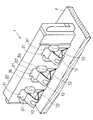
図1〜図3は本発明によるコネクタ1の一実施例を示すもので、10〜10は厚さが0.12mm程度の薄い導電性金属板の打ち抜き、折り曲げ加工等で成形された3個のコンタクト、30は絶縁性合成樹脂で成形されたコネクタハウジング(以下ハウジングと記述する。)、50は相手側電気機器の一例としてのバッテリーパック、Pは基板上に配線パターンが形成されたプリント配線基板である。   1 to 3 show an embodiment of a connector 1 according to the present invention, and 10 to 10 are three pieces formed by stamping, bending or the like of a thin conductive metal plate having a thickness of about 0.12 mm. Contacts, 30 is a connector housing (hereinafter referred to as a housing) formed of an insulating synthetic resin, 50 is a battery pack as an example of a counterpart electric device, and P is a printed wiring board having a wiring pattern formed on the board. It is.

コンタクト10は、ハウジング30に保持される略矩形状の保持部11と、ハウジング30のコンタクト収容室31への収容時にコンタクト収容室31の前面側開口部37から突出する接触部12と、保持部11と接触部12を連結する弾性変形可能な弾性変形部13とを具備している。   The contact 10 includes a substantially rectangular holding portion 11 held by the housing 30, a contact portion 12 protruding from the front opening 37 of the contact housing chamber 31 when the housing 30 is housed in the contact housing chamber 31, and a holding portion. 11 and an elastically deformable elastic portion 13 that connects the contact portion 12 with each other.

弾性変形部13及び接触部12は、保持部11より幅の狭い帯状の薄い導電性金属板を折り曲げた形状に形成されている。
弾性変形部13は、保持部11から接触部12までの間を第1湾曲部14、連結部20及び第2湾曲部15で順次連結した略S字状に形成されている。
第1湾曲部14は、保持部11の上端側から略逆U字状に連設され、その折曲部両側片が略平行に形成されている。
第2湾曲部15は、第1湾曲部14の先端側に延伸された連結部20の先端側から接触部12側へ略V字状に連設され、その折曲部両側片が平行でなく、開口部分が折曲部分より広くなるように、折曲部両側片のなす角度θが鋭角に形成されている。すなわち、第2湾曲部15の折曲部両側片は、その開口部分の広がりが折曲部分の広がりより大きく形成されている。
The elastic deformation portion 13 and the contact portion 12 are formed in a shape obtained by bending a thin strip-like conductive metal plate having a narrower width than the holding portion 11.
The elastic deformation portion 13 is formed in a substantially S shape in which the space from the holding portion 11 to the contact portion 12 is sequentially connected by the first bending portion 14, the connecting portion 20, and the second bending portion 15.
The first bending portion 14 is connected in a substantially inverted U shape from the upper end side of the holding portion 11, and both side pieces of the bent portion are formed substantially in parallel.
The second bending portion 15 is connected in a substantially V shape from the distal end side of the connecting portion 20 extended to the distal end side of the first bending portion 14 to the contact portion 12 side, and the both side pieces of the bent portion are not parallel. The angle θ formed by the both side pieces of the bent portion is formed at an acute angle so that the opening portion is wider than the bent portion. In other words, the opening portion of the second bending portion 15 of the second bending portion 15 has a larger opening than the bending portion.

保持部11の左端側の一部には、板面が保持部11の板面に対して略垂直な連結部16が連設され、この連結部16の下端側の一部には、下方向へ突出した接続部17が連設されている。
保持部11の両側には係止用突起18,18、19,19が突設されている。
接触部12の接点部近傍には、補強用突起(ビード)21が形成されている。
弾性変形部13の第1湾曲部14と第2湾曲部15の間に位置する連結部20の両側部分には、左右対称な部分に位置して変位規制用突起22、22が突設されている。
A connecting part 16 whose plate surface is substantially perpendicular to the plate surface of the holding part 11 is connected to a part on the left end side of the holding part 11, and a downward direction is provided on a part on the lower end side of the connecting part 16. A connecting portion 17 projecting toward the center is provided continuously.
Locking projections 18, 18, 19, 19 are provided on both sides of the holding part 11.
A reinforcing protrusion (bead) 21 is formed in the vicinity of the contact portion of the contact portion 12.
Displacement restricting protrusions 22 and 22 are provided on both side portions of the connecting portion 20 located between the first bending portion 14 and the second bending portion 15 of the elastic deformation portion 13 so as to be located in symmetrical portions. Yes.

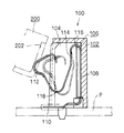
ハウジング30は外形が略横長直方体状に形成され、このハウジング30には、3個のコンタクト10を収容するためのコンタクト収容室31〜31が長手方向に沿って所定ピッチで形成されている。   The outer shape of the housing 30 is formed in a substantially horizontal rectangular parallelepiped shape, and contact housing chambers 31 to 31 for housing the three contacts 10 are formed at a predetermined pitch along the longitudinal direction.

コンタクト収容室31は前面側、底面側及び上面側が開口し、前面側から見た左右の内壁面には、弾性変形部13の変位規制用突起22、22と契合するための、一対の変位規制用係合溝32、32が形成されている。
各変位規制用係合溝32は、底面側(図1では下側)に向かって開口し、溝幅は底面側に向かって途中まで一定に形成され、途中から開口側へ向かうにつれて漸次幅広となるように形成されている。
The contact accommodating chamber 31 is open on the front side, the bottom side, and the top side, and a pair of displacement regulation for engaging with the displacement regulation projections 22 and 22 of the elastic deformation portion 13 on the left and right inner wall surfaces viewed from the front side. Engaging grooves 32, 32 are formed.
Each displacement restricting engagement groove 32 opens toward the bottom surface side (lower side in FIG. 1), and the groove width is formed to be constant halfway toward the bottom surface side, and gradually increases from the middle toward the opening side. It is formed to become.

コンタクト収容室31の前面側から見た左右の内壁面には、奥側の内壁面と交差する隅部に位置して、圧入されたコンタクト10の保持部11を保持するための圧入用係合溝33、33が形成されている。
コンタクト収容室31の前面側から見た左側の壁の内側には、圧入されたコンタクト10の連結部16を収容するための連結部収容部34が形成され、この連結部収容部34は底面側へ向かって開口するとともに、対応する変位規制用係合溝32及び圧入用係合溝33と連通している。
Press fitting engagement for holding the holding portion 11 of the press-fitted contact 10 is located at the corner intersecting the inner wall surface on the back side on the left and right inner wall surfaces viewed from the front side of the contact accommodating chamber 31. Grooves 33 and 33 are formed.
A connecting portion accommodating portion 34 for accommodating the connecting portion 16 of the press-fitted contact 10 is formed inside the left wall as viewed from the front side of the contact accommodating chamber 31. The connecting portion accommodating portion 34 is formed on the bottom side. And is communicated with the corresponding displacement restricting engagement groove 32 and press-fitting engagement groove 33.

ハウジング30の前面には、各コンタクト収容室31の前面側開口部37の両側縁に位置して一対のヘタリ防止用突起35、35が突設されている。このヘタリ防止用突起35、35は、ハウジング30の前面から突出するコンタクト10の接触部12に、バッテリーパック50以外のものから不要な外力が加わってへタリが生じるのを防止するためのものである。   On the front surface of the housing 30, a pair of anti-sticking projections 35, 35 are provided so as to be located on both side edges of the front-side opening 37 of each contact accommodating chamber 31. The anti-sticking protrusions 35 and 35 are provided for preventing the contact portion 12 of the contact 10 protruding from the front surface of the housing 30 from being applied with an unnecessary external force from other than the battery pack 50 and causing dripping. is there.

つぎに組み立て方法について説明する。
図1に示すように、ハウジング30の底面側からコンタクト収容室31内へコンタクト10を挿入する。この挿入によって、保持部11の両側を圧入用係合溝33、33に圧入して係止用突起18,18、19,19を圧入用係合溝33、33の内壁に食い込ませて係止するとともに、連結部16を連結部収容部34に収容し、さらに弾性変形部13の変位規制用突起22、22を変位規制用係合溝32、32に係合し、ハウジング30内にコンタクト10が収容保持される。
このようなハウジング30内へのコンタクト10〜10の収容保持によって、各コンタクト10は、接触部12が対応するコンタクト収容室31の前面側開口部37から前方向へ突出するとともに、接続部17が対応するコンタクト収容室31の底面側から下方向へ突出する。
Next, the assembly method will be described.
As shown in FIG. 1, the contact 10 is inserted into the contact accommodating chamber 31 from the bottom surface side of the housing 30. By this insertion, both sides of the holding portion 11 are press-fitted into the press-fitting engagement grooves 33 and 33, and the locking projections 18, 18, 19 and 19 are bitten into the inner walls of the press-fitting engagement grooves 33 and 33. At the same time, the connecting portion 16 is accommodated in the connecting portion accommodating portion 34, and the displacement restricting protrusions 22, 22 of the elastic deformation portion 13 are engaged with the displacement restricting engaging grooves 32, 32, so that the contact 10 is accommodated in the housing 30. Is held.
By accommodating and holding the contacts 10 to 10 in the housing 30, each contact 10 protrudes forward from the front side opening 37 of the contact accommodating chamber 31 to which the contact portion 12 corresponds, and the connection portion 17 is It protrudes downward from the bottom surface side of the corresponding contact accommodating chamber 31.

前述のように組み立てられたコネクタ1は、図2に示すようにプリント配線基板Pに実装される。具体的には、ハウジング30のコンタクト収容室31〜31に収容保持されたコンタクト10〜10の接続部17〜17をプリント配線基板Pの対応する端子挿入孔に挿入し、半田付けによって基板上の配線パターンに電気的に接続される。例えば、両側のコンタクト10、10の接続部17、17は電線ラインに、真中のコンタクト10の接続部17は信号ラインに電気的に接続される。   The connector 1 assembled as described above is mounted on the printed wiring board P as shown in FIG. Specifically, the connection portions 17 to 17 of the contacts 10 to 10 housed and held in the contact housing chambers 31 to 31 of the housing 30 are inserted into the corresponding terminal insertion holes of the printed wiring board P, and soldered on the board. It is electrically connected to the wiring pattern. For example, the connection portions 17 and 17 of the contacts 10 and 10 on both sides are electrically connected to the electric wire line, and the connection portion 17 of the middle contact 10 is electrically connected to the signal line.

つぎに、前述のようにプリント配線基板Pに実装されたコネクタ1と、相手方電気機器の一例としてのバッテリーパック50との電気的な接続時におけるコンタクト10の変位について、図3を併用して説明する。   Next, the displacement of the contact 10 at the time of electrical connection between the connector 1 mounted on the printed wiring board P as described above and the battery pack 50 as an example of the counterpart electric device will be described with reference to FIG. To do.

図3に実線で示すように、コネクタ1のコンタクト10にバッテリーパック50を押し付け、バッテリーパック50の電極部51をコンタクト10の接触部12に当接し、ついで、バッテリーパック50を矢印方向に動かして二点鎖線で示す位置まで移動させ、接触部12と電極部51の押圧接触(突き当て接触)を完了させたとすると、コンタクト10は同図に二点鎖線で示す状態に弾性変形する。
このとき、弾性変形部13の変位規制用突起22、22がハウジング30の変位規制用係合溝32、32に係合して弾性変形部13の前後方向(図3では左右方向)の変位が規制されているので、弾性変形部13の第2湾曲部15の下方向への変位量が図4の従来例より制限されるとともに、接触部12の上方向への変位量が図4の従来例より大きくなる。このため、第2湾曲部15とプリント配線基板Pの基板面との間隔を小さくして小型化を図ることができるとともに、電極部51と接触部12との押圧接触時の摺動距離Lを長くして良好な接触状態を得ることができる。
As shown by a solid line in FIG. 3, the battery pack 50 is pressed against the contact 10 of the connector 1, the electrode portion 51 of the battery pack 50 is brought into contact with the contact portion 12 of the contact 10, and then the battery pack 50 is moved in the direction of the arrow. If the contact part 12 and the electrode part 51 are moved to the position indicated by the two-dot chain line and the pressing contact (butting contact) is completed, the contact 10 is elastically deformed to the state indicated by the two-dot chain line in FIG.
At this time, the displacement restricting projections 22 and 22 of the elastic deformation portion 13 are engaged with the displacement restricting engagement grooves 32 and 32 of the housing 30, so that the elastic deformation portion 13 is displaced in the front-rear direction (left and right direction in FIG. 3). Since it is regulated, the amount of downward displacement of the second bending portion 15 of the elastic deformation portion 13 is limited as compared with the conventional example of FIG. 4, and the amount of upward displacement of the contact portion 12 is the conventional amount of FIG. Larger than the example. For this reason, the distance between the second bending portion 15 and the substrate surface of the printed wiring board P can be reduced to reduce the size, and the sliding distance L at the time of pressing contact between the electrode portion 51 and the contact portion 12 can be reduced. A long contact can provide a good contact state.

前記実施例では、コネクタの小型化を図りつつ、コンタクトと相手側電気機器の接触部の摺動距離をより長くして良好な接触状態を得ることができるようにするために、第2湾曲部15の折曲部両側片の開口部分の広がりを折曲部分の広がりより大きく形成した場合について説明したが、本発明はこれに限るものではない。
例えば、第2湾曲部15の折曲部両側片を平行として、開口部分の広がりを折曲部分の広がりと同一に形成した場合(例えば第2湾曲部15を略U字状に形成した場合)についても利用することができる。
In the above-described embodiment, the second bending portion can be obtained in order to obtain a good contact state by increasing the sliding distance between the contact portion and the contact portion of the counterpart electric device while reducing the size of the connector. Although the description has been given of the case where the opening portion of each of the 15 bent portion side pieces is larger than the bending portion, the present invention is not limited thereto.
For example, when both sides of the bent portion of the second bending portion 15 are parallel and the opening portion is formed to have the same width as the bending portion (for example, the second bending portion 15 is formed in a substantially U shape). Can also be used.

前記実施例では、弾性変形部の変位規制をバランス良く行うとともに、コンタクトのコンタクト収容室への組み込み時に、変位規制用突起を変位規制用係合部に容易に係合するために、弾性変形部の変位規制用突起が、連結部20の両側であって左右対称な位置に突設された一対の変位規制用突起22、22からなり、変位規制用係合部が、コンタクト収容室31の対向する左右の内壁面の変位規制用突起22、22に対応した部分に形成された一対の変位規制用係合溝32、32からなる場合について説明したが、本発明はこれに限るものではない。
例えば、コンタクトの変位規制用突起を、連結部20の両側であって左右対称でない両側部分に突設した2個若しくは3個以上の変位規制用突起とし、変位規制用係合部を、前記変位規制用突起に係合して変位を規制する変位規制用係合溝や変位規制用係合段部とした場合についても利用することができる。
In the above-described embodiment, the elastic deformation portion is configured so that the displacement of the elastic deformation portion is regulated in a well-balanced manner, and the displacement restriction protrusion is easily engaged with the displacement restriction engagement portion when the contact is incorporated into the contact accommodating chamber. The displacement restricting projections are composed of a pair of displacement restricting projections 22, 22 projecting from both sides of the connecting portion 20 at symmetrical positions, and the displacement restricting engaging portion is opposed to the contact accommodating chamber 31. The case where the left and right inner wall surfaces are formed of a pair of displacement restricting engagement grooves 32 and 32 formed at portions corresponding to the displacement restricting protrusions 22 and 22 has been described, but the present invention is not limited to this.
For example, the displacement restricting protrusions of the contacts are two or more displacement restricting protrusions projecting on both sides of the connecting portion 20 that are not symmetrical, and the displacement restricting engaging portion is the displacement The present invention can also be used in the case of a displacement restricting engagement groove or a displacement restricting engagement step portion that engages with the restricting protrusion to restrict displacement.

本発明によるコネクタ1の一実施例を示すもので、一部を切り欠いて表わした分解斜視図である。1 shows an embodiment of a connector 1 according to the present invention, and is an exploded perspective view partially cut away. 組み立て後のコネクタ1をプリント配線基板Pに実装した状態を示す斜視図である。FIG. 2 is a perspective view showing a state where the assembled connector 1 is mounted on a printed wiring board P. バッテリーパック50の電極部51とコンタクト10の接触部12の弾性接触時における、コンタクト10の変形状態を示す断面図である。4 is a cross-sectional view showing a deformed state of the contact 10 when the electrode portion 51 of the battery pack 50 and the contact portion 12 of the contact 10 are in elastic contact. FIG. 従来例のコネクタ100を示す断面図である。It is sectional drawing which shows the connector 100 of a prior art example.

符号の説明Explanation of symbols

1…コネクタ
10…コンタクト
11…保持部
12…接触部
13…弾性変形部
14…第1湾曲部
15…第2湾曲部
17…接続部
20…連結部
22…変位規制用突起
30…ハウジング
31…コンタクト収容室
32…変位規制用係合溝
37…前面側開口部
50…バッテリーパック(相手側電気機器の一例)
52…電極部(相手側電気機器の接触部の一例)
DESCRIPTION OF SYMBOLS 1 ... Connector 10 ... Contact 11 ... Holding part 12 ... Contact part 13 ... Elastic deformation part 14 ... 1st bending part 15 ... 2nd bending part 17 ... Connection part 20 ... Connection part 22 ... Protrusion 30 for displacement regulation 30 ... Housing 31 ... Contact housing chamber 32 ... Displacement restricting engagement groove 37 ... Front side opening 50 ... Battery pack (an example of a counterpart electric device)
52 .. Electrode part (an example of a contact part of a counterpart electric device)

Claims (3)

コンタクト(10)と、コンタクト(10)を収容するコンタクト収容室(31)が形成されたハウジング(30)とを具備し、コンタクト(10)には、コンタクト(10)をハウジング(30)に保持する保持部(11)と、コンタクト収容室(31)の前面側開口部(37)から突出する接触部(12)と、保持部(11)と接触部(12)の間を連結する弾性変形可能な弾性変形部(13)とが設けられ、弾性変形部(13)は、保持部(11)から接触部(12)までの間を第1湾曲部(14)、連結部(20)及び第2湾曲部(15)で順次連結した略S字状に形成され、接触部(12)と相手側電気機器(50)の接触部(51)との相対的な押圧によって、弾性変形部(13)を撓ませて接触部(12)と接触部(51)を弾性接触させるコネクタであって、弾性変形部(13)の連結部(20)の両側に、前面側から見てコンタクト収容室(31)の左右の内壁面側へ突出する変位規制用突起(22,22)を突設し、コンタクト収容室(31)の左右の内壁面に、変位規制用突起(22,22)に係合して弾性変形部(13)の変位を規則する変位規制用係合部(32,32)を形成したことを特徴とするコネクタ。   A contact (10) and a housing (30) in which a contact accommodating chamber (31) for accommodating the contact (10) is formed. The contact (10) holds the contact (10) in the housing (30). The holding portion (11), the contact portion (12) protruding from the front opening (37) of the contact accommodating chamber (31), and the elastic deformation connecting the holding portion (11) and the contact portion (12). An elastically deformable portion (13), and the elastically deformable portion (13) includes a first curved portion (14), a connecting portion (20), and a portion between the holding portion (11) and the contact portion (12). It is formed in a substantially S-shape that is sequentially connected by the second bending portion (15), and is elastically deformed by the relative pressing between the contact portion (12) and the contact portion (51) of the counterpart electric device (50). 13) bend the contact part (12) and the contact part (51) The displacement restricting projections (22) projecting toward the left and right inner wall surfaces of the contact accommodating chamber (31) when viewed from the front side, on both sides of the connecting portion (20) of the elastically deforming portion (13). , 22) projectingly, and engaging the displacement restricting projections (22, 22) on the left and right inner wall surfaces of the contact accommodating chamber (31) to regulate the displacement of the elastic deformation portion (13). A connector characterized by forming joint portions (32, 32). 弾性変形部(13)の変位規制用突起(22,22)は、連結部(20)の両側であって左右対称な位置に突設された一対の変位規制用突起からなり、変位規制用係合部(32,32)は、コンタクト収容室(31)の対向する左右の内壁面の変位規制用突起(22,22)に対応した部分に形成された一対の変位規制用係合溝からなることを特徴とする請求項1記載のコネクタ。   The displacement restricting projections (22, 22) of the elastically deforming portion (13) are composed of a pair of displacement restricting projections projecting from both sides of the connecting portion (20) at symmetrical positions. The joint portion (32, 32) is composed of a pair of displacement restricting engagement grooves formed in portions corresponding to the displacement restricting protrusions (22, 22) on the left and right inner wall surfaces of the contact accommodating chamber (31). The connector according to claim 1. 弾性変形部(13)の第2湾曲部(15)の折曲部両側片は、その開口部分の広がりが折曲部分の広がりより大きく形成されていることを特徴とする請求項1又は2記載のコネクタ。
3. The bent portion of the second bending portion (15) of the elastic deformation portion (13) is formed such that the opening portion is wider than the bending portion. Connector.
JP2003364070A 2003-10-24 2003-10-24 Connector Pending JP2005129374A (en)

Priority Applications (1)

Application Number Priority Date Filing Date Title
JP2003364070A JP2005129374A (en) 2003-10-24 2003-10-24 Connector

Applications Claiming Priority (1)

Application Number Priority Date Filing Date Title
JP2003364070A JP2005129374A (en) 2003-10-24 2003-10-24 Connector

Publications (2)

Publication Number Publication Date
JP2005129374A true JP2005129374A (en) 2005-05-19
JP2005129374A5 JP2005129374A5 (en) 2006-05-11

Family

ID=34643157

Family Applications (1)

Application Number Title Priority Date Filing Date
JP2003364070A Pending JP2005129374A (en) 2003-10-24 2003-10-24 Connector

Country Status (1)

Country Link
JP (1) JP2005129374A (en)

Cited By (9)

* Cited by examiner, † Cited by third party
Publication number Priority date Publication date Assignee Title
EP1965469A2 (en) 2007-02-28 2008-09-03 J.S.T. Mfg. Co., Ltd. Electrical connector
JP2009163893A (en) * 2007-12-28 2009-07-23 Tyco Electronics Amp Kk Contact member, and electric connector
WO2011030553A1 (en) * 2009-09-14 2011-03-17 タイコエレクトロニクスジャパン合同会社 Electric contact
JP2011103192A (en) * 2009-11-10 2011-05-26 Sumitomo Wiring Syst Ltd Joint connector and wire harness
JP2011134713A (en) * 2009-12-23 2011-07-07 Hon Hai Precision Industry Co Ltd Electrical connector
JP2012174477A (en) * 2011-02-21 2012-09-10 Jst Mfg Co Ltd Electric connector
JP2012174476A (en) * 2011-02-21 2012-09-10 Jst Mfg Co Ltd Electric connector
CN103178376A (en) * 2011-12-22 2013-06-26 泰科电子(上海)有限公司 Electric connector and connector assembly
CN105518942A (en) * 2013-09-09 2016-04-20 诺基亚技术有限公司 Battery connector and manufacturing method therefor

Cited By (10)

* Cited by examiner, † Cited by third party
Publication number Priority date Publication date Assignee Title
EP1965469A2 (en) 2007-02-28 2008-09-03 J.S.T. Mfg. Co., Ltd. Electrical connector
JP2009163893A (en) * 2007-12-28 2009-07-23 Tyco Electronics Amp Kk Contact member, and electric connector
WO2011030553A1 (en) * 2009-09-14 2011-03-17 タイコエレクトロニクスジャパン合同会社 Electric contact
US8821198B2 (en) 2009-09-14 2014-09-02 Tyco Electronics Japan G.K. Surface mounted electrical contact
JP2011103192A (en) * 2009-11-10 2011-05-26 Sumitomo Wiring Syst Ltd Joint connector and wire harness
JP2011134713A (en) * 2009-12-23 2011-07-07 Hon Hai Precision Industry Co Ltd Electrical connector
JP2012174477A (en) * 2011-02-21 2012-09-10 Jst Mfg Co Ltd Electric connector
JP2012174476A (en) * 2011-02-21 2012-09-10 Jst Mfg Co Ltd Electric connector
CN103178376A (en) * 2011-12-22 2013-06-26 泰科电子(上海)有限公司 Electric connector and connector assembly
CN105518942A (en) * 2013-09-09 2016-04-20 诺基亚技术有限公司 Battery connector and manufacturing method therefor

Similar Documents

Publication Publication Date Title
US7845987B2 (en) Electrical connector with plug connector and receptacle connector
US7637786B2 (en) Electrical connector
JP4287825B2 (en) Board connector
US8092232B2 (en) Board-to-board connector
JP2546255Y2 (en) Female terminal fitting
JP5603790B2 (en) Floating connector
JP4851510B2 (en) Electrical connector
JP2007220542A (en) Connector
JP2000133342A (en) Floating electric connector
JP5203029B2 (en) Electrical connector
JP2005129374A (en) Connector
TWI237423B (en) Electrical connector
JP2005129374A5 (en)
JP4482568B2 (en) Electrical connector
JP2005294217A (en) Insulation displacement contact and electric connector using it
JP2001052791A (en) Female terminal and its manufacture
JP2006004896A (en) Connector
JP3681567B2 (en) Board connector
JP7261044B2 (en) male terminal
JPH11307194A (en) Connector
JPH10116658A (en) Connector for substrate
JP2018022682A (en) Receptacle connector and manufacturing method of receptacle connector
JP2004186078A (en) Connector
JP7464215B2 (en) Connector and pair of connectors
JP2012156021A (en) Floating connector

Legal Events

Date Code Title Description
A521 Written amendment

Free format text: JAPANESE INTERMEDIATE CODE: A523

Effective date: 20060317

A621 Written request for application examination

Free format text: JAPANESE INTERMEDIATE CODE: A621

Effective date: 20060317

A977 Report on retrieval

Free format text: JAPANESE INTERMEDIATE CODE: A971007

Effective date: 20080317

A131 Notification of reasons for refusal

Free format text: JAPANESE INTERMEDIATE CODE: A131

Effective date: 20080415

A521 Written amendment

Free format text: JAPANESE INTERMEDIATE CODE: A523

Effective date: 20080616

A131 Notification of reasons for refusal

Free format text: JAPANESE INTERMEDIATE CODE: A131

Effective date: 20080812

RD05 Notification of revocation of power of attorney

Free format text: JAPANESE INTERMEDIATE CODE: A7425

Effective date: 20080812

A02 Decision of refusal

Free format text: JAPANESE INTERMEDIATE CODE: A02

Effective date: 20081205