JP2005294217A - Pressure contact type contact and electrical connector using the same - Google Patents
Pressure contact type contact and electrical connector using the same Download PDFInfo
- Publication number
- JP2005294217A JP2005294217A JP2004111466A JP2004111466A JP2005294217A JP 2005294217 A JP2005294217 A JP 2005294217A JP 2004111466 A JP2004111466 A JP 2004111466A JP 2004111466 A JP2004111466 A JP 2004111466A JP 2005294217 A JP2005294217 A JP 2005294217A
- Authority
- JP
- Japan
- Prior art keywords
- contact
- pair
- press
- elastic
- slot
- Prior art date
- Legal status (The legal status is an assumption and is not a legal conclusion. Google has not performed a legal analysis and makes no representation as to the accuracy of the status listed.)
- Pending
Links
Images
Classifications
-
- A—HUMAN NECESSITIES
- A01—AGRICULTURE; FORESTRY; ANIMAL HUSBANDRY; HUNTING; TRAPPING; FISHING
- A01K—ANIMAL HUSBANDRY; AVICULTURE; APICULTURE; PISCICULTURE; FISHING; REARING OR BREEDING ANIMALS, NOT OTHERWISE PROVIDED FOR; NEW BREEDS OF ANIMALS
- A01K61/00—Culture of aquatic animals
- A01K61/60—Floating cultivation devices, e.g. rafts or floating fish-farms
- A01K61/65—Connecting or mooring devices therefor
-
- H—ELECTRICITY
- H01—ELECTRIC ELEMENTS
- H01R—ELECTRICALLY-CONDUCTIVE CONNECTIONS; STRUCTURAL ASSOCIATIONS OF A PLURALITY OF MUTUALLY-INSULATED ELECTRICAL CONNECTING ELEMENTS; COUPLING DEVICES; CURRENT COLLECTORS
- H01R12/00—Structural associations of a plurality of mutually-insulated electrical connecting elements, specially adapted for printed circuits, e.g. printed circuit boards [PCB], flat or ribbon cables, or like generally planar structures, e.g. terminal strips, terminal blocks; Coupling devices specially adapted for printed circuits, flat or ribbon cables, or like generally planar structures; Terminals specially adapted for contact with, or insertion into, printed circuits, flat or ribbon cables, or like generally planar structures
- H01R12/70—Coupling devices
- H01R12/77—Coupling devices for flexible printed circuits, flat or ribbon cables or like structures
- H01R12/79—Coupling devices for flexible printed circuits, flat or ribbon cables or like structures connecting to rigid printed circuits or like structures
-
- H—ELECTRICITY
- H01—ELECTRIC ELEMENTS
- H01R—ELECTRICALLY-CONDUCTIVE CONNECTIONS; STRUCTURAL ASSOCIATIONS OF A PLURALITY OF MUTUALLY-INSULATED ELECTRICAL CONNECTING ELEMENTS; COUPLING DEVICES; CURRENT COLLECTORS
- H01R12/00—Structural associations of a plurality of mutually-insulated electrical connecting elements, specially adapted for printed circuits, e.g. printed circuit boards [PCB], flat or ribbon cables, or like generally planar structures, e.g. terminal strips, terminal blocks; Coupling devices specially adapted for printed circuits, flat or ribbon cables, or like generally planar structures; Terminals specially adapted for contact with, or insertion into, printed circuits, flat or ribbon cables, or like generally planar structures
- H01R12/70—Coupling devices
- H01R12/71—Coupling devices for rigid printing circuits or like structures
- H01R12/712—Coupling devices for rigid printing circuits or like structures co-operating with the surface of the printed circuit or with a coupling device exclusively provided on the surface of the printed circuit
- H01R12/716—Coupling device provided on the PCB
-
- H—ELECTRICITY
- H01—ELECTRIC ELEMENTS
- H01R—ELECTRICALLY-CONDUCTIVE CONNECTIONS; STRUCTURAL ASSOCIATIONS OF A PLURALITY OF MUTUALLY-INSULATED ELECTRICAL CONNECTING ELEMENTS; COUPLING DEVICES; CURRENT COLLECTORS
- H01R4/00—Electrically-conductive connections between two or more conductive members in direct contact, i.e. touching one another; Means for effecting or maintaining such contact; Electrically-conductive connections having two or more spaced connecting locations for conductors and using contact members penetrating insulation
- H01R4/24—Connections using contact members penetrating or cutting insulation or cable strands
- H01R4/2416—Connections using contact members penetrating or cutting insulation or cable strands the contact members having insulation-cutting edges, e.g. of tuning fork type
- H01R4/2445—Connections using contact members penetrating or cutting insulation or cable strands the contact members having insulation-cutting edges, e.g. of tuning fork type the contact members having additional means acting on the insulation or the wire, e.g. additional insulation penetrating means, strain relief means or wire cutting knives
- H01R4/245—Connections using contact members penetrating or cutting insulation or cable strands the contact members having insulation-cutting edges, e.g. of tuning fork type the contact members having additional means acting on the insulation or the wire, e.g. additional insulation penetrating means, strain relief means or wire cutting knives the additional means having two or more slotted flat portions
- H01R4/2454—Connections using contact members penetrating or cutting insulation or cable strands the contact members having insulation-cutting edges, e.g. of tuning fork type the contact members having additional means acting on the insulation or the wire, e.g. additional insulation penetrating means, strain relief means or wire cutting knives the additional means having two or more slotted flat portions forming a U-shape with slotted branches
-
- H—ELECTRICITY
- H01—ELECTRIC ELEMENTS
- H01R—ELECTRICALLY-CONDUCTIVE CONNECTIONS; STRUCTURAL ASSOCIATIONS OF A PLURALITY OF MUTUALLY-INSULATED ELECTRICAL CONNECTING ELEMENTS; COUPLING DEVICES; CURRENT COLLECTORS
- H01R2201/00—Connectors or connections adapted for particular applications
- H01R2201/16—Connectors or connections adapted for particular applications for telephony
-
- H—ELECTRICITY
- H01—ELECTRIC ELEMENTS
- H01R—ELECTRICALLY-CONDUCTIVE CONNECTIONS; STRUCTURAL ASSOCIATIONS OF A PLURALITY OF MUTUALLY-INSULATED ELECTRICAL CONNECTING ELEMENTS; COUPLING DEVICES; CURRENT COLLECTORS
- H01R43/00—Apparatus or processes specially adapted for manufacturing, assembling, maintaining, or repairing of line connectors or current collectors or for joining electric conductors
- H01R43/16—Apparatus or processes specially adapted for manufacturing, assembling, maintaining, or repairing of line connectors or current collectors or for joining electric conductors for manufacturing contact members, e.g. by punching and by bending
-
- Y—GENERAL TAGGING OF NEW TECHNOLOGICAL DEVELOPMENTS; GENERAL TAGGING OF CROSS-SECTIONAL TECHNOLOGIES SPANNING OVER SEVERAL SECTIONS OF THE IPC; TECHNICAL SUBJECTS COVERED BY FORMER USPC CROSS-REFERENCE ART COLLECTIONS [XRACs] AND DIGESTS
- Y02—TECHNOLOGIES OR APPLICATIONS FOR MITIGATION OR ADAPTATION AGAINST CLIMATE CHANGE
- Y02P—CLIMATE CHANGE MITIGATION TECHNOLOGIES IN THE PRODUCTION OR PROCESSING OF GOODS
- Y02P60/00—Technologies relating to agriculture, livestock or agroalimentary industries
- Y02P60/60—Fishing; Aquaculture; Aquafarming
Landscapes
- Life Sciences & Earth Sciences (AREA)
- Environmental Sciences (AREA)
- Marine Sciences & Fisheries (AREA)
- Zoology (AREA)
- Animal Husbandry (AREA)
- Biodiversity & Conservation Biology (AREA)
- Coupling Device And Connection With Printed Circuit (AREA)
- Connections By Means Of Piercing Elements, Nuts, Or Screws (AREA)
- Multi-Conductor Connections (AREA)
Abstract
【課題】微小サイズであっても相手側コンタクトとの弾性的な圧接状態を確保できる圧接型コンタクトおよびそれを用いた電気コネクタを提供する。
【解決手段】圧接型コンタクト12は、2対の圧接刃35,39と、一対の圧接刃39の外辺39aにそれぞれ連設された一対の弾性接触片32とを備えている。一対の圧接刃39は、被覆電線2を受け容れるスロット41を内辺側に形成するように基部側で結合されて対向し、被覆電線2のスロット41への挿入時に、その被覆部を切断して芯線部に圧接する。弾性接触片32は、スロット41の入口41aとは反対側に向かって延びた弾性挟持部44を有する。この弾性挟持部44は、一対の接点部46を有するとともに、接点部46に向かうに従って幅狭となる先細り形状に形成されている。
【選択図】 図4A pressure contact type contact that can ensure an elastic pressure contact state with a mating contact even with a small size and an electrical connector using the same are provided.
A pressure contact type contact 12 includes two pairs of pressure contact blades 35, 39 and a pair of elastic contact pieces 32 respectively connected to outer sides 39a of the pair of pressure contact blades 39. The pair of press contact blades 39 are coupled and opposed on the base side so as to form a slot 41 for receiving the covered electric wire 2 on the inner side, and cuts the covered portion when the covered electric wire 2 is inserted into the slot 41. And press contact with the core wire. The elastic contact piece 32 has an elastic clamping portion 44 extending toward the opposite side to the inlet 41 a of the slot 41. The elastic clamping portion 44 has a pair of contact portions 46 and is formed in a tapered shape that becomes narrower toward the contact portion 46.
[Selection] Figure 4
Description
この発明は、圧接型コンタクトおよびそれを用いた電気コネクタ(圧接型コネクタ)に関する。 The present invention relates to a pressure contact type contact and an electrical connector (pressure contact type connector) using the same.
被覆電線に取り付けられるコネクタは、樹脂製のハウジングと、このハウジングに固定されたコンタクト(端子金具)とを備えている。被覆電線の被覆部を切り裂く一対の圧接刃の間に被覆電線の芯線部を保持するスロットを形成した構造の圧接型コンタクトを用いると、被覆電線を圧接型コンタクトのスロットに押し込むだけで、コンタクトと被覆電線の芯線部との電気接続を達成できる。このような圧接型コンタクトを用いたコネクタは、圧接型コネクタと呼ばれる。 The connector attached to the covered electric wire includes a resin housing and contacts (terminal fittings) fixed to the housing. When using a press contact type contact with a structure that forms a slot that holds the core part of the covered wire between a pair of press contact blades that cut the covered portion of the covered wire, simply press the covered wire into the slot of the press contact type contact, Electrical connection with the core part of the covered electric wire can be achieved. A connector using such a pressure contact type contact is called a pressure contact type connector.
圧接型コンタクトは、たとえば、特許文献1に示されているように、前記のようなスロットを形成する一対の圧接刃を基部で結合するとともに、それぞれの圧接刃の外辺にベースコネクタ(基板側コネクタ)のコンタクトとの接続のための一対の接触片を連設した構成を有している。この一対の接触片は、前記一対の圧接刃の基部を超えて、前記スロットの入口とは反対側にまで延びた等幅の板状体からなり、その先端部に、ベースコネクタのコンタクトを挟持する一対の接点部を有している。
特許文献1に開示されている圧接型コンタクトでは、一対の接触片の先端部が内方に折り曲げられていて、この折り曲げられた先端部間にベースコネクタのコンタクトを挟持する構成となっている。
しかし、デジタルスチルカメラ、ビデオカメラ、携帯型電話機、PDA(パーソナル・ディジタル・アシスタント)などに代表される最近の小型機器内で使用されるコネクタは、極めて微小なサイズであり、しかも、極数の多い多極コネクタとなっている。それに応じて、圧接型コネクタも微小サイズとならざるをえず、特許文献1の圧接型コンタクトのように、接触片の先端部に折り曲げ部を設ける空間的な余裕はもはや存在しない。
In the press contact type contact disclosed in
However, the connectors used in recent small devices represented by digital still cameras, video cameras, mobile phones, PDAs (personal digital assistants), etc. are extremely small in size, and the number of poles Many multi-pole connectors. Correspondingly, the pressure contact type connector is also inevitably small, and unlike the pressure contact type contact described in
一方、一対の圧接刃間のスロットに被覆電線を挿入すると、スロットが弾性変形して拡開する。このとき、一対の圧接刃は基部を中心に回動することになるから、一対の圧接刃の外辺に連結された一対の接触片もまた回動して、一対の接点間の間隙が狭くなる。微小サイズの圧接型コネクタの場合には、一対の接点間の間隙がなくなり、互いに接触した状態となることも多い。 On the other hand, when the covered electric wire is inserted into the slot between the pair of press contact blades, the slot is elastically deformed and expanded. At this time, since the pair of press contact blades rotate around the base, the pair of contact pieces connected to the outer sides of the pair of press contact blades also rotate, and the gap between the pair of contacts is narrow. Become. In the case of a micro-size pressure contact type connector, there is often no gap between a pair of contact points, and they are often in contact with each other.
このような状態でベースコネクタ側のコンタクトを一対の接点間に挿入すると、これらの接点間が押し広げられることになる。このとき、特許文献1のように先端部に折り曲げ部を有する接触片の場合には、この折り曲げ部の弾性変形および接触片全体の弾性変形が生じ、接点間にベースコネクタ側のコンタクトが弾性的に挟持されることになる。
しかし、接触片の先端部に折り曲げ部を設けることができない微小サイズの圧接型コンタクトの場合には、ベースコネクタ側のコンタクトの受け容れは、専ら、接触片全体の弾性変形に頼らざるをえない。ところが、接触片が等幅の板状体であると、接触片の基部に応力が集中する。つまり、実際には、接触部の基部の弾性変形によって、ベースコネクタ側のコンタクトを受け容れる間隙が一対の接点間に形成されているのである。
When the contact on the base connector side is inserted between the pair of contacts in such a state, the space between the contacts is expanded. At this time, in the case of a contact piece having a bent portion at the tip as in
However, in the case of a micro-sized pressure contact type contact that cannot be bent at the tip of the contact piece, the acceptance of the contact on the base connector side must rely exclusively on the elastic deformation of the entire contact piece. . However, if the contact piece is a plate having a uniform width, stress concentrates on the base of the contact piece. That is, in reality, a gap for receiving the contact on the base connector side is formed between the pair of contacts by elastic deformation of the base portion of the contact portion.
一方、微小サイズの多極コネクタでは、接触片も微小サイズとなっており、ベースコネクタ側のコンタクトを接点間に挿入すると、接触片の拡開変形量は、その基部の弾性変形域を容易に超えて、塑性変形域へと突入する。このような状態では、接触片は、復元力をほとんど失うから、ベース側コネクタ側のコンタクトに接点を弾性的に圧接させることができなくなり、それらの間の電気接続の信頼性が損なわれるおそれがある。 On the other hand, in a micro-sized multi-pole connector, the contact piece is also a small size, and when the contact on the base connector side is inserted between the contact points, the amount of expansion deformation of the contact piece easily makes the elastic deformation area of the base part easier. Beyond, enter the plastic deformation zone. In such a state, since the contact piece loses almost no restoring force, the contact cannot be elastically pressed against the contact on the base side connector side, and the reliability of the electrical connection between them may be impaired. is there.
たとえば、一対の圧接刃の外辺ではなく、それらの基部側に接触片を連設する構成とすれば前記の問題はいくぶん緩和されるであろうが、この場合には、圧接型コンタクトの全高は、圧接刃の高さと接触片の高さとの和となる。つまり、結果として、圧接型コネクタの全高の増加を招くことになり、小型電子機器内で使用される電気コネクタに対する市場の要求に逆行する。 For example, if the contact piece is arranged on the base side instead of the outer sides of the pair of press contact blades, the above-mentioned problem will be alleviated. Is the sum of the height of the press contact blade and the height of the contact piece. That is, as a result, the overall height of the pressure contact type connector is increased, which goes against the market demand for an electrical connector used in a small electronic device.
そこで、この発明の目的は、微小サイズであっても相手側コンタクトとの弾性的な圧接状態を確保できる圧接型コンタクトおよびそれを用いた電気コネクタを提供することである。 Accordingly, an object of the present invention is to provide a pressure contact type contact that can ensure an elastic pressure contact state with a mating contact even if the size is very small, and an electrical connector using the same.
この発明の圧接型コンタクトは、芯線部を被覆部で被覆した被覆電線を受け容れるスロットを内辺側に形成するように基部側で結合されて対向し、前記被覆電線の前記スロットへの挿入時に前記被覆部を切断して前記芯線部に圧接する一対の圧接刃と、この一対の圧接刃の外辺にそれぞれ連設され、前記スロットの入口とは反対側に向かって前記一対の圧接刃の基部を超える位置まで延び、前記一対の圧接刃の基部に対して前記スロットの入口とは反対側の位置に相手側コンタクトを挟持する一対の接点部を有するとともに、前記圧接刃の外辺との連設部と前記接点部との間に前記接点部に向かうに従って幅狭となる先細り形状部を有する板状体で構成された一対の弾性接触片とを含むことを特徴とする。 The pressure contact type contact of the present invention is coupled and opposed on the base side so as to form a slot for receiving the covered electric wire whose core wire portion is covered with the covering portion on the inner side, and when the covered electric wire is inserted into the slot A pair of press contact blades that cut the covering portion and press-contact with the core wire portion, and are connected to the outer sides of the pair of press contact blades, respectively, and the pair of press contact blades toward the side opposite to the inlet of the slot. A pair of contact portions that extend to a position beyond the base and sandwich the mating contact at a position opposite to the slot entrance with respect to the base of the pair of press contact blades; It is characterized by including a pair of elastic contact pieces comprised by the plate-shaped body which has a taper-shaped part which becomes narrow as it goes to the said contact part between a connection part and the said contact part.
また、この発明の電気コネクタは、前記の特徴を有する圧接型コンタクトと、この圧接型コンタクトをコンタクト保持部に保持した樹脂製のハウジングを含むことを特徴とする。
前記圧接型コネクタは、単一の導電性金属板に打ち抜き加工および曲げ加工を施して成形されたものであることが好ましい。
According to another aspect of the present invention, there is provided an electrical connector comprising: a press contact type contact having the above-mentioned characteristics; and a resin housing holding the press contact type contact in a contact holding portion.
It is preferable that the press contact connector is formed by punching and bending a single conductive metal plate.
また、前記先細り形状部は、前記弾性接触片と前記圧接刃の外辺との連設部の前記接点側端部から当該接点部に至る全領域に渡って設けられていてもよい。
また、前記先細り形状部は、板幅の内方に向かって窪むように湾曲した湾曲辺を有していてもよい。
さらに、2対の前記圧接刃が前記スロットを所定方向に整列させた状態で対向配置されており、これらの2対の圧接刃の基部同士が連結板で連結されていてもよい。
Moreover, the said taper-shaped part may be provided over the whole area | region from the said contact side edge part of the connection part of the said elastic contact piece and the outer edge of the said press contact blade to the said contact part.
The tapered portion may have a curved side that is curved so as to be recessed toward the inside of the plate width.
Further, the two pairs of press contact blades may be arranged to face each other with the slots aligned in a predetermined direction, and the base portions of these two pairs of press contact blades may be connected by a connecting plate.
この場合、前記弾性接触片は、一方の対の圧接刃の外辺に連設され、他方の対の圧接刃とは反対側に延びて形成されていてもよい。この場合、連結板の両端に2対の圧接刃がそれぞれ連設され、その側辺に、ハウジングの内壁に係合する抜け止め突起が形成されるとよい。
また、前記弾性接触片は、一方の対の圧接刃の外辺に連設され、他方の対の圧接刃に向かって延びて形成されていてもよい。この場合、ハウジングの内壁に係合する抜け止め突起を弾性接触片の接点部とは反対側の端縁に設けるとよい。
In this case, the elastic contact piece may be formed to be connected to the outer side of one pair of press contact blades and extend to the opposite side of the other pair of press contact blades. In this case, it is preferable that two pairs of press contact blades are connected to both ends of the connecting plate, and a retaining protrusion that engages with the inner wall of the housing is formed on the side thereof.
The elastic contact piece may be formed continuously with the outer side of one pair of press contact blades and extending toward the other pair of press contact blades. In this case, it is preferable to provide a retaining protrusion that engages with the inner wall of the housing on the edge of the elastic contact piece opposite to the contact portion.
この発明によれば、一対の弾性接触片は、接点部に向かうに従って幅狭となる先細り形状部を有しているため、一対の接点部間に相手側コンタクトを挟持させたとき、前記先細り形状部において応力が分散する。これにより、等幅の板状体で弾性接触片を構成した場合に比較して、応力の集中を抑制することができ、先細り形状部全体が撓る(しなる)ように弾性変形するから、弾性接触片全体の弾性変形域を大きくとることができる。 According to this invention, since the pair of elastic contact pieces has the tapered shape portion that becomes narrower toward the contact portion, the tapered shape is obtained when the counterpart contact is sandwiched between the pair of contact portions. Stress is dispersed in the part. As a result, compared to the case where the elastic contact piece is configured with an equal-width plate-like body, the stress concentration can be suppressed, and the entire tapered portion is elastically deformed so as to bend (become). The elastic deformation area of the entire elastic contact piece can be increased.
したがって、一対の圧接刃間のスロットに被覆電線を挿入(圧入)することに伴って弾性接触片が回動し、その接点部間の間隙が狭くなった状態(あるいは無くなった状態)から、この接点部間に相手側コンタクトを挿入しても、弾性接触片の変形量が弾性変形域を超えて塑性変形域に突入することを抑制または防止できる。そのため、当該圧接型コンタクトが微小サイズに構成される場合であっても、前記接点部を相手側コンタクトに弾性的に圧接させる状態を確保でき、電気接続の信頼性を高めることができる。 Therefore, the elastic contact piece rotates as the covered electric wire is inserted (press-fitted) into the slot between the pair of press contact blades, and the gap between the contact portions is reduced (or lost) from this state. Even if the mating contact is inserted between the contact portions, it is possible to suppress or prevent the deformation amount of the elastic contact piece from exceeding the elastic deformation region and entering the plastic deformation region. Therefore, even when the press contact type contact is configured in a very small size, it is possible to ensure a state in which the contact portion is elastically pressed to the mating contact and to improve the reliability of electrical connection.
しかも、弾性接触片は圧接刃の外辺に連設して設けられているので、圧接型コンタクトの全高が高くなることもなく、したがって、電気コネクタの全高が高くなることもない。
このようにして、微小サイズおよび低背型でありながら、電気接続信頼性の高い電気コネクタを実現できる。
In addition, since the elastic contact piece is provided continuously to the outer side of the press contact blade, the overall height of the press contact type contact does not increase, and therefore the overall height of the electrical connector does not increase.
In this way, an electrical connector with high electrical connection reliability can be realized while having a small size and a low profile.
以下では、この発明の実施の形態を、添付図面を参照して詳細に説明する。
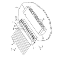
図1は、この発明の一実施形態に係る電気コネクタの使用状態を説明するための斜視図である。この実施形態の電気コネクタ1は、複数本の被覆電線2に結合された電線側コネクタである。この電線側コネクタ1は、たとえば、配線基板3上に表面実装された基板側コネクタ(ベースコネクタ)4に結合可能である。電線側コネクタ1を基板側コネクタ4に結合させることにより、被覆電線2が配線基板3に電気接続されることになる。
Hereinafter, embodiments of the present invention will be described in detail with reference to the accompanying drawings.
FIG. 1 is a perspective view for explaining a usage state of an electrical connector according to an embodiment of the present invention. The
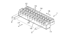
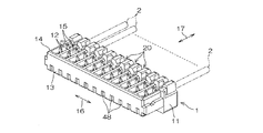
図2および図3は、前記電線側コネクタ1を使用状態とは上下反転した姿勢で示す斜視図であり、図2は被覆電線2が結合される後方側から見た状態を示し、図3は、その反対の前方側(基板側コネクタ4側)からみた状態を示す。
この電線側コネクタ1は、合成樹脂成型品からなるハウジング11と、このハウジング11に圧入されて保持された圧接型コンタクト(端子金具)12とを有している。ハウジング11は、大略的に、直方体の箱形形状に形成されている。このハウジング11の前面13側には、底面(使用状態において配線基板3に対向する側の面)14に開口した溝状のコンタクト保持部15が、ハウジング11の幅方向16に沿って複数個並設されている。各コンタクト保持部15は、幅方向16と直交する被覆電線2の軸方向17に沿って形成されていて、ハウジング11の底面14側から圧接型コンタクト12を圧入することができ、この圧入された圧接型コンタクト12を保持することができるように形成されている。
2 and 3 are perspective views showing the wire-
The electric
コンタクト保持部15よりもハウジング11の後面18寄りの位置には、複数のコンタクト保持部15にそれぞれ対応する複数の電線保持部20が幅方向16に沿って複数個並設されている。
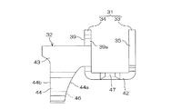
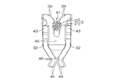
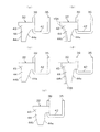
図4は、圧接型コンタクト12の斜視図である。また、図5は、圧接型コンタクト12の側面図であり、図4の矢印R11方向に見た構成が示されている。さらに、図6は、圧接型コンタクト12の正面図であり、図4の矢印R12方向に見た構成が示されている。
A plurality of
FIG. 4 is a perspective view of the pressure
圧接型コンタクト12は、単一の導電性金属薄板(たとえば、めっきした銅板)に打ち抜き加工および折り曲げ加工を施して形成された一体品である。この圧接型コンタクト12は、被覆電線2が結合される圧接部31をハウジング11の後面18側に相当する後方に有し、基板側コネクタ4のコンタクト51(図1参照)に接触する一対の弾性接触片32を前方に有している。
The pressure
圧接部31は、前後に間隔を開けて配置された第1圧接部33および第2圧接部34を有している。第1圧接部33は、一対の圧接刃35と、この一対の圧接刃35を対向状態に保持するようにそれらの基部(根元部)で連結する連結部36とを有している。一対の圧接刃35は、その内辺により、被覆電線2の芯線部が圧入されて保持されるスロット37を区画している。同様に、第2圧接部34は、スロット41を区画する一対の圧接刃39を有し、この一対の圧接刃39がその基部(根元部)で連結部40によって連結されている。そして、連結部36,40間が底板部42(連結板)によって結合されている。つまり、底板部42の両端辺に第1および第2圧接部33,34が結合されている。この底板部42の両側部には、ハウジング11のコンタクト保持部15に圧入されたときに、このコンタクト保持部15の内壁に食い込んで当該圧接型コンタクト12をコンタクト保持部15に保持する圧入突起47が、側方に突出して形成されている。
The
一対の弾性接触片32は、第2圧接部34の一対の圧接刃39の外辺39aから前方に向かって互いに平行に延びた一対の側板部(圧接刃の外辺との連設部)43と、この側板部43から、被覆電線2の軸方向に直交する方向に延びて形成された一対の弾性挟持部44とを有している。この一対の弾性挟持部44は、側板部43から、一対の圧接刃39が形成するスロット41の入口41aとは反対方向に向かって、圧接刃39とほぼ平行な方向(被覆電線2の軸方向と直交する方向)に延びて形成されている。より具体的には、一対の弾性挟持部44は、一対の側板部43から互いに徐々に近接していくようにやや内方に傾斜して延びており、最近接部を過ぎてから拡開方向に傾斜した案内傾斜部45を各先端に有している。そして、一対の弾性挟持部44の最近接部が、基板側コネクタ4のコンタクト51(図1参照)を弾性的に挟持する接点部46となっている。つまり、これらの弾性挟持部44は、一対の圧接刃39の基部である連結部40に対して、スロット41の入口41aとは反対側の位置にまで延びて形成されており、その接点部46は、連結部40に対して、スロット41の入口41aとは反対の位置にある。
The pair of
図1に示されているように、ハウジング11の上面28には、基板側コネクタ4のコンタクト51を受け入れるコンタクト受け入れ溝48が被覆電線2の軸方向17に沿って形成されている。このコンタクト受け入れ溝48内に圧接型コンタクト12の弾性挟持部44が入り込むようになっている。
図5に最もよく表されているように、弾性挟持部44は、側板部43から接点部46に至る全範囲において、接点部46に向かうに従って幅狭となる先細り形状の板状体となっていて、先細り形状部を形成している。さらに、この実施形態では、弾性挟持部44は、圧接刃39側の側辺44aが、板幅方向内側に窪む凹湾曲線状に形成されており、その反対側の側辺44bは、圧接刃39の立設方向に沿う直線状に形成されている。
As shown in FIG. 1, a
As best shown in FIG. 5, the
このような先細り形状の弾性挟持部44は、一対の接点部46間に基板側コネクタ4のコンタクト51が挿入されたときに、全体が撓るように弾性変形し、局所的に応力が集中することがない。そのため、弾性変形域が大きく、基板側コネクタ4のコンタクト51の挿入によって塑性変形が生じることを抑制または防止できる。
被覆電線2をスロット41に圧入すると、一対の圧接刃39の内辺によって、被覆電線2の被覆部21が切り裂かれ、これらの一対の圧接刃39の内辺が被覆電線2の芯線22に圧接する。このとき、一対の圧接刃39は、図6において二点鎖線で示すように、その基部である連結部40を支点として拡開するようにそれぞれ回動する。これにより、圧接刃39の弾性変形が生じ、その復元力によって、被覆電線2の芯線22がそれらの間に挟持される。
Such a tapered
When the covered
一方、一対の圧接刃39の拡開変形によって、これらの外辺39aに結合された一対の弾性接触片32では、一対の弾性挟持部44が、前記連結部40の近傍を支点として、それらの接点部46同士が近接する方向に回動することになる。これにより、接点部46間の隙間が狭くなるか、あるいは無くなる。
この状態で、電線側コネクタ1を基板側コネクタ4に装着すると、基板側コネクタ4のコンタクト51は、一対の接点部46間を押し広げて、これらの間に入り込んで挟持されることになる。このとき、一対の弾性挟持部44は、全体が撓るように弾性変形し、その復元力によってコンタクト51を挟持する。一対の弾性挟持部44は、応力の集中を防いで弾性変形域を大きくとれる形状に形成されているため、コンタクト51の挿入によって、その塑性変形が生じることがなく、これにより、コンタクト51と接点部46との電気接続を良好に保持することができる。
On the other hand, in the pair of
When the electric
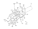
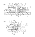
図7(a)は電線側コネクタ1および基板側コネクタ4の嵌合前の状態を示す断面図であり、図7(b)は電線側コネクタ1および基板側コネクタ4を嵌合した状態を示す断面図である。基板側コネクタ4は、樹脂成型品からなるハウジング50と、このハウジング50に圧入保持された複数本のコンタクト51とを有している。ハウジング50には、電線側コネクタ1に対向する前方に開口した嵌合孔52が形成されており、この嵌合孔52に電線側コネクタ1のハウジング11の前方部分が嵌合されることになる。
FIG. 7A is a cross-sectional view showing a state before the
複数本のコンタクト51は、ハウジング50の後方から圧入されており、電線側コネクタ1の挿入方向と平行な方向に沿って並設された状態でハウジング50に保持されている。各コンタクト51は、嵌合孔52内に突出する接点部53と、この接点部53の後端から配線基板3の実装面3aに向かって垂下し、この配線基板3の表面に半田付けされる接合部54と、この接合部54の途中部から前方に突出して、ハウジング50内の圧入孔57に圧入される圧入片55とを有している。コンタクト51は、接点部53が端子挿入孔56に圧入されるとともに、圧入片55が圧入孔57に圧入されることによって、ハウジング50に圧入固定されている。
The plurality of
電線側コネクタ1を基板側コネクタ4に挿入すると、電線側コネクタ1のハウジング11の前面13が基板側コネクタ4の嵌合孔52の内奥面58に当接するか、またはハウジング11に形成された段部27が基板側コネクタ4のハウジング50の口縁部59に当接することによって、被覆電線2の軸方向17に関して、電線側コネクタ1および基板側コネクタ4の相互の相対位置が規制される。また、電線側コネクタ1のハウジング11の前方部が基板側コネクタ4の嵌合孔52に嵌合することによって、電線側コネクタ1のコンタクト受け入れ溝48に、基板側コネクタ4のコンタクト51の接点部53が正確に位置合わせされて導入される。これにより、この接点部53は、コンタクト受け入れ溝48内で圧接型コンタクト12の一対の接点部46によって弾性的に挟持される。このようにして、コンタクト12,51間の電気接続が達成され、被覆電線2が配線基板3に電気的に接続されることになる。
When the wire-
以上のようにこの実施形態によれば、圧接型コンタクト12の弾性接触片32に備えられた弾性挟持部44は、接点部46に向かうに従って幅狭となる先細り形状の板状体からなっており、これにより、応力の集中を防いで、弾性変形域を大きくとることができる構成となっている。そのため、スロット37,40への被覆電線2の挿入によって、これらのスロット37,40を形成する圧接刃35,39が拡開変形し、それに伴って、一対の弾性挟持部44が接点部46同士の間隔を狭めるように回動したとしても、一対の接点部46間へのコンタクト51の挿入時に、弾性挟持部44の変形量が塑性変形域に達することがない。これにより、信頼性の高い電気接続が可能になる。
As described above, according to this embodiment, the
しかも、弾性挟持部44は、折り返し部などの無い単純な板状体でありながら弾性変形域を大きくとることができる構造であるので、コネクタ1が微小サイズであり、したがって、圧接型コンタクト12全体が微小サイズに構成される場合であっても、十分な弾性変形域を確保することができる。これにより、微小サイズのコネクタの電気接続信頼性を格段に向上することができる。
Moreover, since the
さらに、弾性接触片32は、圧接刃39の外辺39aに連設された連設部としての側板部43と、この側板部43に連設する弾性挟持部44とで構成されているため、圧接型コンタクト12の全高は、圧接刃39の高さと弾性接触片32の高さとの和よりも低くなる。これにより、コネクタ1の高さを低くすることができ、小型電子機器の内部での用途に適した低背型のコネクタを実現することができる。
Furthermore, since the
このように、この実施形態によれば、小型かつ低背型のコネクタにおける電気接続の信頼性の向上が実現される。
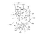
図8は、この発明の他の実施形態を説明するための図であり、前記の圧接型コンタクト12に代えて用いることができる圧接型コンタクト12Aの斜視図である。この図9において、前述の図4に示された各部に対応する部分には、図4の場合と同一の参照符号を付して示す。
Thus, according to this embodiment, the reliability of electrical connection in a small and low profile connector is improved.
FIG. 8 is a view for explaining another embodiment of the present invention, and is a perspective view of a pressure
この圧接型コンタクト12Aでは、第2圧接部34の一対の圧接刃39の外辺39aから、第1圧接部33に向かって延びるように側板部43が形成されている。この構成の場合、底板部42に圧入突起を設けることができない。そこで、この実施形態では、一対の側板部43の上端縁(スロット37,41の入口側)に、コンタクト保持部15の内壁に食い付く一対の抜け止め突起25がそれぞれ外方に傾斜した姿勢に形成されている。
In the press
このような構成によっても、前述の第1の実施形態の場合と同様の効果を奏することができる。
図9は、弾性挟持部44の形状の変形例を示す図解的な側面図である。前記の実施形態の場合の弾性挟持部44の形状が、図9(a)に示されている。図9(b)は、側辺44a,44bの両方を板幅方向内側に窪む凹湾曲線状に形成した例である。図9(c)は、側辺44aを圧接刃39の立設方向に対して傾斜した直線状に形成し、弾性挟持部44を側面視において全体として逆台形形状に形成した例である。図9(d)は、側辺44a,44bの両方を圧接刃39の立設方向に対して傾斜した直線状として略等脚の逆台形形状に形成した例である。図9(e)は、側辺44a,44bを、板幅方向外方に突出した凸湾曲線状に形成した例である。むろん、側辺44a,44bのいずれか一方のみを凸湾曲線状に形成してもよい。
Even with such a configuration, the same effects as in the case of the first embodiment described above can be obtained.
FIG. 9 is a schematic side view showing a modification of the shape of the
弾性挟持部44における応力集中を最も緩和することができる形状は、図9(b)の形状である。しかし、この形状の場合には、ハウジング11のコンタクト保持部15の内壁と弾性挟持部44の先端部との距離が大きくなり、基板側コネクタ4のコンタクト51をコンタクト受け入れ溝48(図7参照)によって接点6間の位置に確実に案内できなくなるおそれがある。この問題は、コンタクト保持部15の内壁面の形状を、参照符号15Aで示すように、弾性挟持部44の側辺44bに沿う凸湾曲面形状とすることにより解決できる。図9(a)の形状の弾性挟持部44の場合には、側辺44bが圧接刃39の立設方向に沿う直線状であるので、問題がない。
The shape that can most alleviate the stress concentration in the
同様に、図9(c)(d)の構成の比較では、図9(d)の構成の方が、応力を分散するうえで効果的である。この図9(d)の構成を採用するときには、コンタクト保持部15の内壁の形状を参照符号15Bで示すように、弾性挟持部44の側辺44bに沿う傾斜面形状として、弾性挟持部44とコンタクト保持部15の内壁面との距離を狭めることが好ましい。
以上、この発明のいくつかの実施形態について説明したが、この発明はさらに他の形態で実施することもできる。たとえば、上述の実施形態では、11極型の電線側コネクタについて例示したが、電線側コネクタの極数に特別の制限はなく、たとえば、2極型や20極型の電線側コネクタについても同様の構成を採用できる。
Similarly, in the comparison of the configurations of FIGS. 9C and 9D, the configuration of FIG. 9D is more effective in distributing the stress. 9D, when the shape of the inner wall of the
As mentioned above, although several embodiment of this invention was described, this invention can also be implemented with another form. For example, in the above-described embodiment, the eleven-pole type electric wire side connector is illustrated, but there is no particular limitation on the number of poles of the electric wire side connector, and the same applies to, for example, the two-pole type or the 20-pole type electric wire side connector. Configuration can be adopted.
また、前述の実施形態では、弾性挟持部44は、側板部43から接点部46に至る全範囲において、接点部46に向かうに従って幅狭となるように形成されているが、この範囲の一部において、接点部46に向かうに従って幅狭となる部分を設けることによっても、応力の分散を図ることができる。
また、プレス加工時の応力の集中を緩和するために、角部を極力少なくすることが好ましいから、弾性挟持部44の先端部に角部には、アールを付けて、湾曲線形状のコーナー部とする方が好ましい。
In the above-described embodiment, the
Further, since it is preferable to reduce the corners as much as possible in order to alleviate the stress concentration during the press working, the corners of the
その他、特許請求の範囲に記載された事項の範囲で種々の設計変更を施すことが可能である。 In addition, various design changes can be made within the scope of matters described in the claims.
1 電気コネクタ(圧接型コネクタ)
2 被覆電線
3 配線基板
4 基板側コネクタ
11 ハウジング
12 圧接型コンタクト
12A 圧接型コンタクト
15 コンタクト保持部
21 被覆部
22 芯線
25 抜け止め突起
31 圧接部
32 弾性接触片
33 第1圧接部
34 第2圧接部
35 圧接刃
36 連結部
37 スロット
39 圧接刃
39a 圧接刃の外辺
40 連結部
41 スロット
41a スロットの入口
42 底板部
43 側板部
44 弾性挟持部
44a 側辺
44b 側辺
46 接点部
47 圧入突起
48 コンタクト受け入れ溝
51 コンタクト
1 Electrical connector (pressure contact type connector)
DESCRIPTION OF
Claims (2)
この一対の圧接刃の外辺にそれぞれ連設され、前記スロットの入口とは反対側に向かって前記一対の圧接刃の基部を超える位置まで延び、前記一対の圧接刃の基部に対して前記スロットの入口とは反対側の位置に相手側コンタクトを挟持する一対の接点部を有するとともに、前記圧接刃の外辺との連設部と前記接点部との間に前記接点部に向かうに従って幅狭となる先細り形状部を有する板状体で構成された一対の弾性接触片とを含むことを特徴とする圧接型コンタクト。 It is coupled and opposed on the base side so as to form a slot for receiving the covered electric wire whose core wire portion is covered with the covering portion on the inner side, and the covering portion is cut when the covered electric wire is inserted into the slot. A pair of press contact blades pressed against the core wire portion;
The slot is connected to the outer sides of the pair of press contact blades, extends to a position opposite to the inlet of the slot to a position exceeding the base of the pair of press contact blades, and the slot with respect to the base of the pair of press contact blades A pair of contact portions sandwiching the mating contact at a position opposite to the inlet of the blade, and narrower toward the contact portion between the contact portion and the connection portion with the outer side of the press contact blade. And a pair of elastic contact pieces made of a plate-like body having a tapered portion.
この圧接型コンタクトをコンタクト保持部に保持した樹脂製のハウジングを含むことを特徴とする電気コネクタ。 The press contact type contact according to claim 1,
An electrical connector comprising a resin housing in which the press contact type contact is held by a contact holding portion.
Priority Applications (4)
| Application Number | Priority Date | Filing Date | Title |
|---|---|---|---|
| JP2004111466A JP2005294217A (en) | 2004-04-05 | 2004-04-05 | Pressure contact type contact and electrical connector using the same |
| KR1020050028031A KR101110148B1 (en) | 2004-04-05 | 2005-04-04 | Press-fit contacts and electrical connectors using them |
| US11/097,135 US7056146B2 (en) | 2004-04-05 | 2005-04-04 | Insulation displacement contact and electric connector using the same |
| CNA200510062675XA CN1681161A (en) | 2004-04-05 | 2005-04-05 | Crimp connection contact and electric connector using the same |
Applications Claiming Priority (1)
| Application Number | Priority Date | Filing Date | Title |
|---|---|---|---|
| JP2004111466A JP2005294217A (en) | 2004-04-05 | 2004-04-05 | Pressure contact type contact and electrical connector using the same |
Publications (1)
| Publication Number | Publication Date |
|---|---|
| JP2005294217A true JP2005294217A (en) | 2005-10-20 |
Family
ID=35054964
Family Applications (1)
| Application Number | Title | Priority Date | Filing Date |
|---|---|---|---|
| JP2004111466A Pending JP2005294217A (en) | 2004-04-05 | 2004-04-05 | Pressure contact type contact and electrical connector using the same |
Country Status (4)
| Country | Link |
|---|---|
| US (1) | US7056146B2 (en) |
| JP (1) | JP2005294217A (en) |
| KR (1) | KR101110148B1 (en) |
| CN (1) | CN1681161A (en) |
Cited By (3)
| Publication number | Priority date | Publication date | Assignee | Title |
|---|---|---|---|---|
| JP2010010034A (en) * | 2008-06-30 | 2010-01-14 | Jst Mfg Co Ltd | Electrical connector |
| CN103986002A (en) * | 2013-02-12 | 2014-08-13 | 日本压着端子制造株式会社 | Electric connector |
| US9825376B2 (en) | 2016-03-25 | 2017-11-21 | J.S.T. Mfg. Co., Ltd. | Pressure welding contact having a bellows type terminal and pressure welding connector |
Families Citing this family (13)
| Publication number | Priority date | Publication date | Assignee | Title |
|---|---|---|---|---|
| CN201252208Y (en) * | 2008-06-11 | 2009-06-03 | 富士康(昆山)电脑接插件有限公司 | Electric connector and conducting terminator thereof |
| TW201042844A (en) * | 2009-05-26 | 2010-12-01 | Compal Electronics Inc | Electrical connector and terminal connecting element thereof |
| TWM391741U (en) * | 2009-12-10 | 2010-11-01 | Hon Hai Prec Ind Co Ltd | Electrical connector |
| TWM383849U (en) * | 2009-12-11 | 2010-07-01 | Hon Hai Prec Ind Co Ltd | Electrical connector |
| TWM406833U (en) * | 2010-12-14 | 2011-07-01 | Ant Percision Industry Co Ltd | Terminal structure and electrical connector using the same |
| DE102012103599A1 (en) * | 2012-04-24 | 2013-10-24 | Wago Verwaltungsgesellschaft Mbh | Insulation displacement connector for connecting with circuit board and for attaching electric conductor, has overload protection device to suppress the movement of spring element along extending direction of cutting edge portion |
| KR101255125B1 (en) | 2012-07-31 | 2013-04-15 | (주)한신단자공업 | Electric wire connector |
| US8974245B2 (en) * | 2013-08-05 | 2015-03-10 | Hubbell Incorporated | Grounding electrical connector |
| CN106971876B (en) * | 2017-04-11 | 2019-02-26 | 潘昌雄 | One kind exempting from the self-locking connection shallow bid multiple cord switch of wire stripping |
| JP7196035B2 (en) * | 2019-08-23 | 2022-12-26 | 日本航空電子工業株式会社 | Connector and connection method |
| JP7360310B2 (en) * | 2019-11-27 | 2023-10-12 | タイコエレクトロニクスジャパン合同会社 | contacts and connectors |
| US11476623B2 (en) | 2020-11-05 | 2022-10-18 | Leviton Manufacturing Co., Inc. | Staggered contact |
| US12469989B2 (en) | 2022-08-17 | 2025-11-11 | Leviton Manufacturing Co., Inc. | Insulation displacement contact capable of securely terminating a wide range of electrical conductors |
Family Cites Families (10)
| Publication number | Priority date | Publication date | Assignee | Title |
|---|---|---|---|---|
| JPS5942785A (en) | 1982-08-31 | 1984-03-09 | 日本圧着端子製造株式会社 | Electric connector |
| JPS6068568A (en) | 1983-09-26 | 1985-04-19 | 山一電機株式会社 | Manufacturing method for connectors for coated conductor wires |
| JPS6175071U (en) | 1984-10-22 | 1986-05-21 | ||
| JPS61116773A (en) | 1984-11-12 | 1986-06-04 | 株式会社エルコ・インターナショナル | Insulator housing for comression connector |
| JPS61224277A (en) | 1985-03-29 | 1986-10-04 | 沖電気工業株式会社 | U-groove connection terminal |
| JPH0621184A (en) | 1992-07-06 | 1994-01-28 | Matsushita Electron Corp | Analyzing method for failure of semiconductor device |
| DE29504996U1 (en) * | 1995-03-24 | 1995-07-13 | Stocko Metallwarenfab Henkels | Electrical contact element |
| JPH10116658A (en) | 1996-10-14 | 1998-05-06 | Sumitomo Wiring Syst Ltd | Connector for substrate |
| JP3412740B2 (en) | 1997-01-13 | 2003-06-03 | 住友電装株式会社 | Terminal fitting |
| USD464322S1 (en) * | 2000-05-19 | 2002-10-15 | J.S.T. Mfg. Co. Ltd. | Electric contact |
-
2004
- 2004-04-05 JP JP2004111466A patent/JP2005294217A/en active Pending
-
2005
- 2005-04-04 US US11/097,135 patent/US7056146B2/en not_active Expired - Lifetime
- 2005-04-04 KR KR1020050028031A patent/KR101110148B1/en not_active Expired - Fee Related
- 2005-04-05 CN CNA200510062675XA patent/CN1681161A/en active Pending
Cited By (4)
| Publication number | Priority date | Publication date | Assignee | Title |
|---|---|---|---|---|
| JP2010010034A (en) * | 2008-06-30 | 2010-01-14 | Jst Mfg Co Ltd | Electrical connector |
| CN103986002A (en) * | 2013-02-12 | 2014-08-13 | 日本压着端子制造株式会社 | Electric connector |
| JP2014154453A (en) * | 2013-02-12 | 2014-08-25 | Jst Mfg Co Ltd | Electric connector |
| US9825376B2 (en) | 2016-03-25 | 2017-11-21 | J.S.T. Mfg. Co., Ltd. | Pressure welding contact having a bellows type terminal and pressure welding connector |
Also Published As
| Publication number | Publication date |
|---|---|
| CN1681161A (en) | 2005-10-12 |
| KR20060045488A (en) | 2006-05-17 |
| US7056146B2 (en) | 2006-06-06 |
| US20050221658A1 (en) | 2005-10-06 |
| KR101110148B1 (en) | 2012-02-06 |
Similar Documents
| Publication | Publication Date | Title |
|---|---|---|
| JP4287825B2 (en) | Board connector | |
| CN1653650B (en) | connection terminal | |
| JP3746106B2 (en) | Board electrical connector | |
| US20080076277A1 (en) | Electrical connector | |
| JP3272263B2 (en) | Connector with terminal runout prevention mechanism | |
| JP2000251965A (en) | Electric connector | |
| JP2005294217A (en) | Pressure contact type contact and electrical connector using the same | |
| JP2005129255A (en) | Connector and connector system | |
| US5716230A (en) | Surface engageable electrical connector | |
| CN101983458B (en) | Contact and electric connector | |
| JP6784580B2 (en) | Connector device with a disconnection prevention structure | |
| CN100505421C (en) | electrical connector | |
| JP2016173998A (en) | Contact and connector employing the contact | |
| CN119542792A (en) | Connector components | |
| JP4851510B2 (en) | Electrical connector | |
| JPH11339906A (en) | Substrate mount connector | |
| JP4021397B2 (en) | Connection terminal and joint connector using the connection terminal | |
| JP4314106B2 (en) | Female terminal | |
| JP2850109B2 (en) | Connection terminal | |
| JP2008171627A (en) | Female terminal fitting | |
| US20050277332A1 (en) | Surface mountable electrical connector | |
| US20060270274A1 (en) | Electrical connector with low profile | |
| JP2015220172A (en) | Terminal structure and connector | |
| US20050170674A1 (en) | Socket connector | |
| JP2004296419A (en) | Connector |
Legal Events
| Date | Code | Title | Description |
|---|---|---|---|
| A977 | Report on retrieval |
Free format text: JAPANESE INTERMEDIATE CODE: A971007 Effective date: 20071015 |
|
| A131 | Notification of reasons for refusal |
Free format text: JAPANESE INTERMEDIATE CODE: A131 Effective date: 20071113 |
|
| A521 | Request for written amendment filed |
Free format text: JAPANESE INTERMEDIATE CODE: A523 Effective date: 20080115 |
|
| A131 | Notification of reasons for refusal |
Free format text: JAPANESE INTERMEDIATE CODE: A131 Effective date: 20080212 |
|
| A02 | Decision of refusal |
Free format text: JAPANESE INTERMEDIATE CODE: A02 Effective date: 20080610 |