JP2005128200A - Heating device - Google Patents
Heating device Download PDFInfo
- Publication number
- JP2005128200A JP2005128200A JP2003362801A JP2003362801A JP2005128200A JP 2005128200 A JP2005128200 A JP 2005128200A JP 2003362801 A JP2003362801 A JP 2003362801A JP 2003362801 A JP2003362801 A JP 2003362801A JP 2005128200 A JP2005128200 A JP 2005128200A
- Authority
- JP
- Japan
- Prior art keywords
- temperature
- range
- heating
- heating roller
- detection unit
- Prior art date
- Legal status (The legal status is an assumption and is not a legal conclusion. Google has not performed a legal analysis and makes no representation as to the accuracy of the status listed.)
- Withdrawn
Links
Images

Landscapes
- Fixing For Electrophotography (AREA)
Abstract
【課題】 ヒートローラのローラ面の温度のばらつきを低減させることのできる加熱装置を提供する。
【解決手段】 シートに当接する加熱ローラと、前記加熱ローラの前記シートに当接する領域を加熱する熱源と、前記加熱ローラの前記熱源により加熱される領域の温度を検知する第1の温度検知部と、前記加熱ローラにより加熱可能な最大サイズのシートの前記加熱ローラの回転軸方向における少なくとも一方の端部が当接する位置近傍の前記加熱ローラの温度を検知する第2の温度検知部と、前記第1および第2の温度検知部により検知された温度に基づいて前記熱源を制御する制御部とを有する。
【選択図】 図2PROBLEM TO BE SOLVED: To provide a heating device capable of reducing variations in temperature of a roller surface of a heat roller.
A heating roller that contacts a sheet, a heat source that heats a region of the heating roller that contacts the sheet, and a first temperature detection unit that detects a temperature of a region heated by the heat source of the heating roller. A second temperature detection unit that detects the temperature of the heating roller in the vicinity of a position where at least one end of the maximum size sheet that can be heated by the heating roller contacts in the rotation axis direction of the heating roller; And a controller that controls the heat source based on the temperatures detected by the first and second temperature detectors.
[Selection] Figure 2
Description
本発明は、加熱装置に関するものである。 The present invention relates to a heating device.
シートへの画像形成時の定着処理に使用される加熱装置において、薄肉円筒形状のヒートローラによる加熱定着を行う場合に、ヒートローラの長手方向(ローラの回転軸方向)全域を一様に加熱してA4−Rサイズ等の幅(シートを搬送する方向と直交する方向におけるサイズ)がヒートローラの長手方向のサイズよりも狭いシートを印刷すると、ヒートローラのローラ面のうちシートに接しない部分は温度がシートに奪われることがないので、過熱状態になる場合がある。 When heating and fixing with a thin-walled cylindrical heat roller in a heating device used for fixing processing when forming an image on a sheet, the entire length of the heat roller (the rotation axis direction of the roller) is uniformly heated. When a sheet having a width such as A4-R size (size in a direction orthogonal to the sheet conveying direction) is narrower than the size in the longitudinal direction of the heat roller, the portion of the roller surface of the heat roller that does not contact the sheet is Since the temperature is not taken away by the seat, it may become overheated.
このような過熱状態となることを抑制するため、ヒートローラを加熱するための熱源をA4−Rサイズのシートの幅前後の大きさで分割し、センタ部分(シートが通過する領域)とサイド部分(シートが通過しない領域)とが同一温度になるように加熱制御することが一般的に行われている(例えば、特許文献1から5参照。)。
In order to suppress such an overheating state, the heat source for heating the heat roller is divided into sizes around the width of the A4-R size sheet, and the center portion (region through which the sheet passes) and the side portion In general, the heating control is performed so that the temperature of the sheet (the region through which the sheet does not pass) is the same (see, for example,
具体的に、ヒートローラの熱源としてはIH(Induction Heating)を使用している。この熱源は、A4−Rサイズのシートの幅と略同じサイズのセンタ部熱源と、A3サイズのシートの幅まで加熱できるようにセンタ部熱源の両サイドにそれぞれ配置されているサイド部熱源の3つから構成されている。 Specifically, IH (Induction Heating) is used as a heat source of the heat roller. This heat source includes a center part heat source having a size substantially the same as the width of the A4-R size sheet, and three side part heat sources arranged on both sides of the center part heat source so as to be heated up to the width of the A3 size sheet. It consists of two.
ヒートローラの長手方向におけるセンタ部熱源により加熱される領域の中央近傍にはセンタ温度センサが配置されている。センタ部熱源は、センタ温度センサによる検知温度に基づいて制御される。また、ヒートローラの長手方向におけるサイド部熱源により加熱される領域の中央近傍にはサイド温度センサが配置されている。サイド部熱源は、サイド温度センサによる検知温度に基づいて制御される。なお、サイド部熱源は2つに分かれているが、電気的には繋がっているため、サイド温度センサはいずれか一方のサイド部熱源による加熱領域近傍に配置されており、2つのサイド部熱源は1つのサイド温度センサによる検知温度に基づいて制御される。 A center temperature sensor is disposed in the vicinity of the center of the region heated by the center heat source in the longitudinal direction of the heat roller. The center heat source is controlled based on the temperature detected by the center temperature sensor. Further, a side temperature sensor is disposed in the vicinity of the center of the region heated by the side heat source in the longitudinal direction of the heat roller. The side part heat source is controlled based on the temperature detected by the side temperature sensor. Although the side part heat source is divided into two, since it is electrically connected, the side temperature sensor is arranged in the vicinity of the heating region by one of the side part heat sources, and the two side part heat sources are Control is performed based on the temperature detected by one side temperature sensor.
一般的には、センタ温度センサによる検知温度とサイド温度センサによる検知温度とが略同じになるように加熱制御される。 Generally, heating control is performed so that the temperature detected by the center temperature sensor and the temperature detected by the side temperature sensor are substantially the same.
また、ヒートローラの長手方向における、ヒートローラが対応可能な最大サイズ(例えば、A3サイズ)のシートの端部(幅)位置、あるいはその端部位置の外側にエッジ温度センサを配置している。このエッジ温度センサによる検知温度(ヒートローラ端部の温度)が所定の温度値を超えた場合には、加熱動作を停止させるなど、安全装置として用いられている。
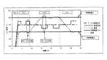
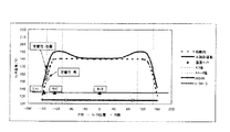
従来の温度制御においては、印刷待機中〜印刷開始直後の間、ヒートローラの長手方向における両端部の温度は低下(ヒートローラの両端部はベアリング、駆動ギヤ等によって熱を奪われ易いため温度が低下している。)しており、印刷開始直後の画像に関してはシートの幅方向における端部の定着不良が発生する場合がある(図15の破線参照)。 In the conventional temperature control, the temperature at both ends in the longitudinal direction of the heat roller is reduced during printing standby and immediately after the start of printing (because both ends of the heat roller are easily deprived of heat by bearings, drive gears, etc.) In the case of an image immediately after the start of printing, there may be a case where an improper fixing at the end in the width direction of the sheet occurs (see the broken line in FIG. 15).
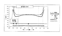
一方、複数枚のシートに連続して印刷動作を行う場合、ヒートローラの長手方向におけるシートの幅方向端部よりも外側部分は、シートに触れないため熱を奪われず、温度が上昇し易い。このような温度上昇は、高温オフセットを生ずる原因ともなる。さらに、ヒートローラ、ベアリングおよび駆動ギヤ等の耐熱温度を超えると部品に不具合が生じる場合もある(図16の破線参照)。 On the other hand, when a printing operation is continuously performed on a plurality of sheets, the outer portion of the heat roller in the longitudinal direction than the end in the width direction of the sheet does not touch the sheet, so heat is not taken away and the temperature is likely to rise. Such a temperature rise also causes a high temperature offset. Furthermore, if the heat resistance temperature of the heat roller, the bearing, the drive gear, etc. is exceeded, there may be a problem with the component (see the broken line in FIG. 16).
このような場合、ヒートローラによる加熱動作を停止して印刷を中断し、温度低下を待つ必要があり、生産性の低下を招いてしまう。 In such a case, it is necessary to stop the heating operation by the heat roller, interrupt printing, and wait for the temperature to drop, leading to a reduction in productivity.
上述のような問題が発生しないよう考慮して熱源の全長が決められるが、薄肉化されている等、熱容量が小さいヒートローラでは両者の問題を共に解消することは困難である。 The total length of the heat source is determined in consideration of the occurrence of the above-mentioned problems, but it is difficult to solve both problems with a heat roller having a small heat capacity such as being thin.
本発明は上述した問題点を解決するためになされたものであり、ヒートローラのローラ面の温度のばらつきを低減させることのできる加熱装置を提供することを目的とする。 The present invention has been made to solve the above-described problems, and an object of the present invention is to provide a heating device that can reduce the temperature variation of the roller surface of the heat roller.
上述した課題を解決するため、本発明に係る加熱装置は、シートに当接する加熱ローラと、前記加熱ローラの前記シートに当接する領域を加熱する熱源と、前記加熱ローラの前記熱源により加熱される領域の温度を検知する第1の温度検知部と、前記加熱ローラにより加熱可能な最大サイズのシートの前記加熱ローラの回転軸方向における少なくとも一方の端部が当接する位置近傍の前記加熱ローラの温度を検知する第2の温度検知部と、前記第1および第2の温度検知部により検知された温度に基づいて前記熱源を制御する制御部とを有する。 In order to solve the above-described problems, a heating device according to the present invention is heated by a heating roller that contacts a sheet, a heat source that heats a region of the heating roller that contacts the sheet, and the heat source of the heating roller. The temperature of the heating roller in the vicinity of a position where at least one end in the rotation axis direction of the heating roller of the maximum size sheet that can be heated by the heating roller is in contact with the first temperature detection unit that detects the temperature of the region And a control unit that controls the heat source based on the temperatures detected by the first and second temperature detection units.
また、上述のような加熱装置において、前記制御部は、前記第2の温度検知部により検知した温度に基づいて前記熱源を制御するための目標温度を設定するようにしてもよい。 In the heating device as described above, the control unit may set a target temperature for controlling the heat source based on the temperature detected by the second temperature detection unit.
従来の加熱装置では、ヒートローラを加熱する熱源が複数に分割されているような場合でも、全ての熱源が同じ目標温度になるように温度制御を行っていたが、上述のような構成とすることにより、一部の熱源(例えば、ヒートローラ中央部分の熱源)は常時同じ目標温度で温度制御し、他の熱源(例えば、ヒートローラ端部(サイド部)の熱源)は第2の温度検知部により検知した温度に基づいて温度制御の目標温度を変化させるといったことが可能となる。これにより、より適切且つ効果的な温度制御が可能となり、ヒートローラのローラ面の温度のばらつきを低減させることができる。 In the conventional heating apparatus, even when the heat source for heating the heat roller is divided into a plurality of parts, the temperature control is performed so that all the heat sources have the same target temperature. As a result, some heat sources (for example, the heat source at the center of the heat roller) always control the temperature at the same target temperature, and other heat sources (for example, the heat source at the end (side) of the heat roller) detect the second temperature. The target temperature for temperature control can be changed based on the temperature detected by the unit. Thereby, more appropriate and effective temperature control becomes possible, and variation in temperature of the roller surface of the heat roller can be reduced.
さらに、このような構成の加熱装置において、前記第2の温度検知部は、前記最大サイズのシートの前記少なくとも一方の端部が前記加熱ローラに当接する位置から前記回転軸方向において±5mmの範囲内に配置されており、前記制御部は、前記第2の温度検知部により検知した温度が所定の適正温度範囲における下限温度以下であるとき、前記目標温度を前記所定の適正温度範囲における上限温度と前記下限温度との平均温度から前記上限温度までの範囲に設定することもできる。 Furthermore, in the heating apparatus having such a configuration, the second temperature detection unit has a range of ± 5 mm in the rotation axis direction from a position where the at least one end of the maximum size sheet contacts the heating roller. And when the temperature detected by the second temperature detection unit is equal to or lower than a lower limit temperature in a predetermined appropriate temperature range, the control unit sets the target temperature to an upper limit temperature in the predetermined appropriate temperature range. And an average temperature between the lower limit temperature and the upper limit temperature.
また、上述のような構成の加熱装置において、前記第2の温度検知部は、前記最大サイズのシートの前記少なくとも一方の端部が前記加熱ローラに当接する位置から前記回転軸方向において±5mmの範囲内に配置されており、前記制御部は、前記第2の温度検知部により検知した温度が所定の適正温度範囲内にあるとき、前記目標温度を前記所定の適正温度範囲における上限温度と下限温度との平均温度に設定するようにしてもよい。 Further, in the heating apparatus having the above-described configuration, the second temperature detection unit is ± 5 mm in the rotation axis direction from a position where the at least one end of the maximum size sheet contacts the heating roller. When the temperature detected by the second temperature detection unit is within a predetermined appropriate temperature range, the control unit sets the target temperature to an upper limit temperature and a lower limit in the predetermined appropriate temperature range. You may make it set to the average temperature with temperature.
なお、このような構成の加熱装置において、前記第2の温度検知部は、前記最大サイズのシートの前記少なくとも一方の端部が前記加熱ローラに当接する位置から前記回転軸方向において±5mmの範囲内に配置されており、前記制御部は、前記第2の温度検知部により検知した温度が所定の適正温度範囲における上限温度以上であるとき、前記目標温度を前記所定の適正温度範囲における下限温度から前記下限温度と上限温度との平均温度までの範囲に設定することも可能である。 In the heating apparatus having such a configuration, the second temperature detection unit has a range of ± 5 mm in the rotation axis direction from a position where the at least one end of the maximum size sheet contacts the heating roller. And when the temperature detected by the second temperature detection unit is equal to or higher than an upper limit temperature in a predetermined appropriate temperature range, the control unit sets the target temperature to a lower limit temperature in the predetermined appropriate temperature range. To the average temperature of the lower limit temperature and the upper limit temperature.
この他、上述のような加熱装置において、前記第2の温度検知部は、前記最大サイズのシートの前記少なくとも一方の端部が前記加熱ローラに当接する位置から前記回転軸方向において5mm以上外側に配置されており、前記制御部は、前記第2の温度検知部により検知した温度が所定の適正温度範囲における下限温度以下であるとき、前記目標温度を前記所定の適正温度範囲における前記下限温度と上限温度との平均温度から前記上限温度までの範囲に設定する構成とすることもできる。 In addition, in the heating apparatus as described above, the second temperature detection unit may be located outside by 5 mm or more in the rotation axis direction from a position where the at least one end of the maximum size sheet contacts the heating roller. And when the temperature detected by the second temperature detector is equal to or lower than a lower limit temperature in a predetermined appropriate temperature range, the control unit sets the target temperature as the lower limit temperature in the predetermined appropriate temperature range. It can also be set as the range set to the range from the average temperature with upper limit temperature to the said upper limit temperature.
また、上述のような加熱装置において、前記第2の温度検知部は、前記最大サイズのシートの前記少なくとも一方の端部が前記加熱ローラに当接する位置から前記回転軸方向において5mm以上外側に配置されており、前記制御部は、前記第2の温度検知部により検知した温度が所定の適正温度範囲における下限温度から前記所定の適正温度範囲における上限温度と前記加熱ローラ周辺部品の耐熱温度との平均温度までの範囲内にあるとき、前記目標温度を前記所定の適正温度範囲における前記下限温度と上限温度との平均温度に設定することが好ましい。 Further, in the heating apparatus as described above, the second temperature detection unit is disposed outside by 5 mm or more in the rotation axis direction from a position where the at least one end of the maximum size sheet contacts the heating roller. The controller detects a temperature detected by the second temperature detector from a lower limit temperature in a predetermined appropriate temperature range to an upper limit temperature in the predetermined appropriate temperature range and a heat resistant temperature of the peripheral component of the heating roller. When the temperature is within the range up to the average temperature, the target temperature is preferably set to an average temperature of the lower limit temperature and the upper limit temperature in the predetermined appropriate temperature range.
もちろん、上述のような構成の加熱装置において、前記第2の温度検知部は、前記最大サイズのシートの前記少なくとも一方の端部が前記加熱ローラに当接する位置から前記回転軸方向において5mm以上外側に配置されており、前記制御部は、前記第2の温度検知部により検知した温度が所定の適正温度範囲における上限温度と前記加熱ローラ周辺部品の耐熱温度との平均温度から前記加熱ローラ周辺部品の耐熱温度までの範囲内にあるとき、前記目標温度を前記所定の適正温度範囲における下限温度から前記所定の適正温度範囲における前記下限温度と上限温度との平均温度までの範囲に設定することもできる。 Of course, in the heating apparatus having the above-described configuration, the second temperature detection unit is 5 mm or more outside in the rotation axis direction from the position where the at least one end of the maximum size sheet contacts the heating roller. The control unit is configured to determine whether the temperature detected by the second temperature detection unit is an average temperature between an upper limit temperature in a predetermined appropriate temperature range and a heat resistance temperature of the heating roller peripheral component. The target temperature may be set to a range from a lower limit temperature in the predetermined appropriate temperature range to an average temperature of the lower limit temperature and the upper limit temperature in the predetermined appropriate temperature range. it can.
この他、上述のような加熱装置において、前記第2の温度検知部は、前記最大サイズのシートの前記少なくとも一方の端部が前記加熱ローラに当接する位置から前記回転軸方向において5mm以上外側に配置されており、前記制御部は、前記第2の温度検知部により検知した温度が前記加熱ローラ周辺部品の耐熱温度以上であるとき、前記熱源による加熱動作を停止もしくは抑制させる構成とすることもできる。 In addition, in the heating apparatus as described above, the second temperature detection unit may be located outside by 5 mm or more in the rotation axis direction from a position where the at least one end of the maximum size sheet contacts the heating roller. The control unit may be configured to stop or suppress the heating operation by the heat source when the temperature detected by the second temperature detection unit is equal to or higher than the heat resistance temperature of the peripheral component of the heating roller. it can.
また、上述のような加熱装置を備え、前記加熱装置によりシートへのトナー像の定着動作を行う画像形成装置を構成することも可能である。 It is also possible to configure an image forming apparatus that includes the heating device as described above and performs a fixing operation of a toner image onto a sheet by the heating device.
以上に詳述したように本発明によれば、ヒートローラのローラ面の温度のばらつきを低減させることのできる加熱装置を提供することができる。 As described in detail above, according to the present invention, it is possible to provide a heating device that can reduce the temperature variation of the roller surface of the heat roller.
以下、本発明の実施の形態について図面を参照しつつ説明する。
(第1の実施の形態)
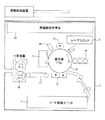
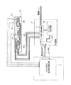
図1は本発明の第1の実施の形態による加熱装置およびこれを備えた画像形成装置を説明するための図、図2はヒートローラ(後述)による加熱動作を実現するための機能ブロック図である。
Embodiments of the present invention will be described below with reference to the drawings.
(First embodiment)
FIG. 1 is a diagram for explaining a heating device according to a first embodiment of the present invention and an image forming apparatus including the same, and FIG. 2 is a functional block diagram for realizing a heating operation by a heat roller (described later). is there.
本実施の形態による画像形成装置1は、シート供給ユニット11、感光体ドラム12、クリーナ13、除電ランプ14、帯電チャージャ15、現像器16、搬送ベルト17、プレスローラ18、ヒートローラ(加熱ローラ)19およびレーザユニットLを備えている。なお、ヒートローラ19とプレスローラ18とから定着器が構成されている。
The
また、同図に示すように原稿読取光学系20を備えることによって、さらにスキャナとしての役割および複写機としての役割を有する画像処理装置を構成することも可能である。
Further, by providing the original reading
同図に示す画像形成装置1の動作について簡単に説明する。
The operation of the
シート供給ユニット11に収納されているシートは、不図示のピックアップローラによりシート搬送路に供給される。帯電チャージャ15により感光体ドラム12の感光面が均一に帯電されると、この感光面に対してレーザユニットLから画像変調されたレーザビームによる露光が行われる。これにより感光面に静電潜像が形成される。
The sheets stored in the sheet supply unit 11 are supplied to the sheet conveyance path by a pickup roller (not shown). When the photosensitive surface of the
次に、静電潜像が形成された感光体ドラムの感光面に対して現像機16による現像処理が施される。これにより、感光面の露光部にはトナーが付着し、感光面上にトナー像が形成される。
Next, development processing by the developing
感光面上に形成されたトナー像は、転写・剥離チャージャCまで搬送されたシートのシート面に転写され、トナー像が転写されたシートは感光体ドラム12の感光面から剥離される。
The toner image formed on the photosensitive surface is transferred to the sheet surface of the sheet conveyed to the transfer / peeling charger C, and the sheet having the toner image transferred is peeled off from the photosensitive surface of the
感光面から剥離されたシートは、搬送ベルト17により定着器へと搬送される。定着器に搬送されたシートは、ヒートローラ19とプレスローラ18との間で挟持され、ヒートローラ19に加熱されることによってシート面にトナー像が定着される。
The sheet peeled from the photosensitive surface is conveyed to the fixing device by the
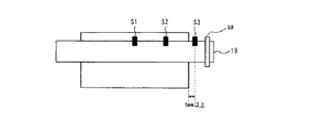
なお、本実施の形態においても、ヒートローラ19の長手方向(回転軸方向)にはサイド部熱源CSとセンタ部熱源CCとが配列されており、これらの熱源により加熱されるヒートローラ19のローラ面の温度を検知するためにサイド温度センサ(第1の温度検知部)S2、センタ温度センサS1、エッジ温度センサ(第2の温度検知部)S3が配置されている(図2参照)。これら熱源およびセンサはヒートローラ19に対して従来の構成と同様な位置関係で配列されている。なお、これらサイド温度センサS2、センタ温度センサS1およびエッジ温度センサS3はサーミスタから構成されている。
In the present embodiment also, the side heat source CS and the center heat source CC are arranged in the longitudinal direction (rotational axis direction) of the
これらサイド温度センサS2、センタ温度センサS1、エッジ温度センサS3により検知された温度情報は、CPUを含む温度制御回路4へと送られる。 The temperature information detected by the side temperature sensor S2, the center temperature sensor S1, and the edge temperature sensor S3 is sent to a temperature control circuit 4 including a CPU.
温度制御回路4は、これらの温度センサにより検知した温度情報を受け取ると、これらの温度情報に基づいて電力設定信号もしくは電力ON/OFF信号をIH回路3に送信する。
Upon receiving the temperature information detected by these temperature sensors, the temperature control circuit 4 transmits a power setting signal or a power ON / OFF signal to the
IH回路3では、温度制御回路4から受け取った各種信号をフォトカプラ33により受信する。なお、フォトカプラ33は、エラー信号を温度制御回路4に送信する役割も有している。
In the
フォトカプラ33にて受信した信号は、CPUを含む制御回路32を介してIH電源/駆動回路31へと送られる。そして、IH電源/駆動回路31によってサイド部熱源CSおよびセンタ部熱源CCによる加熱動作が制御される(すなわち、ヒートローラ19のローラ面の温度が制御される。)。これら温度制御回路4およびIH回路3から制御部が構成されている。
The signal received by the
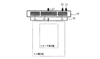
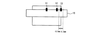
図3および図4に、当該ヒートローラで対応可能な最大サイズ(例えば、A3サイズ)のシートと各温度センサとの位置関係を示す。図4に示すように、エッジ温度センサS3は最大サイズのシートの少なくとも一方の端部が加熱ローラ19に当接する位置から加熱ローラ19の回転軸方向において±5mmの範囲内に配置されている。
FIG. 3 and FIG. 4 show the positional relationship between the maximum size (for example, A3 size) sheet that can be handled by the heat roller and each temperature sensor. As shown in FIG. 4, the edge temperature sensor S <b> 3 is arranged within a range of ± 5 mm in the direction of the rotation axis of the
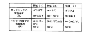
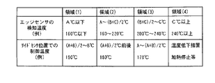
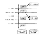
本実施の形態による加熱装置では、シートへのトナーの適正な定着温度範囲の下限温度をA℃(例えば、160℃)、上限温度をB℃(例えば、200℃)とした場合、エッジ温度センサS3により検知された温度に基づいて、サイド部熱源の目標温度を図5に示す表のように設定する。以下の目標温度の設定は、温度制御回路4およびIH回路3からなる制御部により行われる。
In the heating device according to the present embodiment, when the lower limit temperature of the proper fixing temperature range of the toner to the sheet is A ° C. (eg, 160 ° C.) and the upper limit temperature is B ° C. (eg, 200 ° C.), the edge temperature sensor Based on the temperature detected by S3, the target temperature of a side part heat source is set like the table | surface shown in FIG. The following target temperature is set by a control unit including the temperature control circuit 4 and the
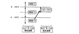
具体的には、エッジ温度センサS3により検知した温度が下限温度A℃(160℃)以下である場合(図5および図6における領域(1)に該当)は、熱源を温度制御する目標温度を上限温度B℃(200℃)と下限温度A℃(160℃)との平均温度(180℃)から上限温度B℃(200℃)までの範囲に設定する。 Specifically, when the temperature detected by the edge temperature sensor S3 is equal to or lower than the lower limit temperature A ° C. (160 ° C.) (corresponding to the region (1) in FIGS. 5 and 6), the target temperature for temperature control of the heat source is set. The temperature is set in a range from an average temperature (180 ° C.) of an upper limit temperature B ° C. (200 ° C.) and a lower limit temperature A ° C. (160 ° C.) to an upper limit temperature B ° C. (200 ° C.).
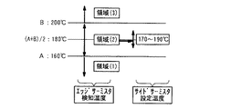
次に、エッジ温度センサS3により検知した温度が所定の適正温度範囲(160℃〜200℃)内にある場合は(図5および図7における領域(2)に該当)、目標温度を上限温度B℃(200℃)と下限温度A℃(160℃)との平均温度(180℃)に設定する。 Next, when the temperature detected by the edge temperature sensor S3 is within a predetermined appropriate temperature range (160 ° C. to 200 ° C.) (corresponding to the region (2) in FIGS. 5 and 7), the target temperature is set to the upper limit temperature B. It sets to the average temperature (180 degreeC) of (degreeC) (200 degreeC) and lower limit temperature A degreeC (160 degreeC).
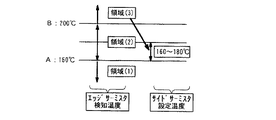
さらに、エッジ温度センサS3により検知した温度が上限温度B℃(200℃)以上である場合は(図5および図8における領域(3)に該当)、目標温度を下限温度A℃(160℃)から下限温度と上限温度との平均温度(180℃)までの範囲に設定する。 Furthermore, when the temperature detected by the edge temperature sensor S3 is equal to or higher than the upper limit temperature B ° C. (200 ° C.) (corresponding to the region (3) in FIGS. 5 and 8), the target temperature is set to the lower limit temperature A ° C. (160 ° C.). To the average temperature (180 ° C.) of the lower limit temperature and the upper limit temperature.
図9は、本装置におけるヒートローラ19の温度制御について説明するための図である。ヒートローラ19はセンタ温度センサS1とサイド温度センサS2で温度を検知し、センタ及びサイド温度センサ近傍のヒートローラ温度は、熱源の出力により図9に示す目標温度になるよう温度制御される。
FIG. 9 is a diagram for explaining the temperature control of the
センタ部熱源CCの目標温度はトナーの定着温度の最適値(180℃)に固定されており、サイド部熱源CSの目標温度はエッジ温度センサにより検知される温度に基づいて規定される。すなわち、サイド部熱源CSの温度制御は、エッジ温度センサおよびサイド温度センサによる検出温度に基づいて行われる。 The target temperature of the center heat source CC is fixed to the optimum value (180 ° C.) of the toner fixing temperature, and the target temperature of the side heat source CS is defined based on the temperature detected by the edge temperature sensor. That is, the temperature control of the side heat source CS is performed based on the temperature detected by the edge temperature sensor and the side temperature sensor.
以上のように、レディ中やプリント開始直後などのエッジ温度センサS3による検知温度が低いとき(例えば、160℃以下)は、サイド部熱源CSの目標温度を高めに設定(例えば、190℃)するので、エッジ温度センサS3により検知されるヒートローラ温度は適正な定着温度範囲内となり、プリント開始直後の対応可能な最大サイズのシートの(例えば、A3)端部の定着不良は発生しない(図15の実線参照)。 As described above, when the temperature detected by the edge temperature sensor S3 is low (for example, 160 ° C. or less) during the ready or immediately after the start of printing, the target temperature of the side heat source CS is set high (for example, 190 ° C.). Therefore, the heat roller temperature detected by the edge temperature sensor S3 is within an appropriate fixing temperature range, and fixing failure at the end of the maximum size sheet (for example, A3) that can be handled immediately after the start of printing does not occur (FIG. 15). (See the solid line).
また、A3サイズ等の連続プリント時などのエッジ温度センサS3による検知温度が高いとき(例えば、200℃以上)は、サイド部熱源CSの目標温度を低めに設定(例えば、170℃)するので、ヒートローラ端部における温度上昇は抑制される(図16の実線参照)。 Also, when the temperature detected by the edge temperature sensor S3 is high (for example, 200 ° C. or higher) during continuous printing such as A3 size, the target temperature of the side heat source CS is set lower (for example, 170 ° C.). Temperature rise at the end of the heat roller is suppressed (see the solid line in FIG. 16).
なお、エッジ温度センサS3による検知温度が中間的な温度であるとき(例えば、160〜200℃)は、サイド部熱源CSの目標温度をセンタ部熱源CCと同じ目標温度(180℃)にする。
(第2の実施の形態)
次に、本発明の第2の実施の形態について説明する。
When the temperature detected by the edge temperature sensor S3 is an intermediate temperature (for example, 160 to 200 ° C.), the target temperature of the side heat source CS is set to the same target temperature (180 ° C.) as the center heat source CC.
(Second Embodiment)
Next, a second embodiment of the present invention will be described.
本実施の形態は、上述の第1の実施の形態の変形例である。以下、上述の第1の実施の形態と構成が同様である部分については同一符号を付し、説明は割愛する。 The present embodiment is a modification of the above-described first embodiment. Hereinafter, the same reference numerals are given to the same components as those in the first embodiment, and the description thereof is omitted.
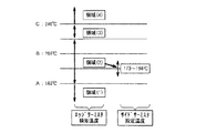
本実施の形態による加熱装置では、図10に示すように、エッジ温度センサの位置を最大紙サイズ(A3サイズ等)幅の端を0とした場合、5mm以上外側に配置されている(すなわち、最大サイズのシートの少なくとも一方の端部が加熱ローラに当接する位置から加熱ローラの回転軸方向において5mm以上外側に配置されている。)。 In the heating device according to the present embodiment, as shown in FIG. 10, when the edge of the maximum paper size (A3 size, etc.) width is set to 0, the position of the edge temperature sensor is arranged outside by 5 mm or more (that is, (At least one end of the maximum size sheet is disposed outside the heating roller by 5 mm or more in the direction of the rotation axis of the heating roller).
ここでは、シートへのトナーの適正な定着温度範囲の下限温度をA℃(例えば、160℃)、上限温度をB℃(例えば、200℃)とした場合、加熱ローラ19及び加熱ローラの端部周辺の部品(ベアリングBR、不図示の駆動ギヤ等)の耐熱温度がC℃(例えば、240℃)であるとき、エッジ温度センサS3による検知温度に基づいて、サイド部熱源CSの目標温度を図11に示す表のように設定する。
Here, when the lower limit temperature of the proper fixing temperature range of the toner on the sheet is A ° C. (eg, 160 ° C.) and the upper limit temperature is B ° C. (eg, 200 ° C.), the
具体的には、エッジ温度センサS3により検知した温度が下限温度A℃(160℃)以下である場合(図11および図12における領域(1)に該当)は、熱源を温度制御する目標温度を下限温度と上限温度との平均温度(180℃)から上限温度B℃(200℃)までの範囲に設定する。 Specifically, when the temperature detected by the edge temperature sensor S3 is equal to or lower than the lower limit temperature A ° C. (160 ° C.) (corresponding to the region (1) in FIGS. 11 and 12), the target temperature for temperature control of the heat source is set. The temperature is set in a range from an average temperature (180 ° C.) of the lower limit temperature and the upper limit temperature to an upper limit temperature B ° C. (200 ° C.).
次に、エッジ温度センサS3により検知した温度が所定の適正温度範囲(160℃〜200℃)における下限温度A℃(160℃)から上限温度B℃(200℃)と加熱ローラ周辺部品の耐熱温度C℃(240℃)との平均温度までの範囲内にある場合(図11および図13における領域(2)に該当)は、目標温度を下限温度A℃と上限温度B℃との平均温度前後(例えば、160℃〜180℃)に設定する。 Next, the temperature detected by the edge temperature sensor S3 ranges from the lower limit temperature A ° C (160 ° C) to the upper limit temperature B ° C (200 ° C) in the predetermined appropriate temperature range (160 ° C to 200 ° C) and the heat resistant temperature of the peripheral parts of the heating roller. When the temperature is within the range up to the average temperature of C ° C. (240 ° C.) (corresponding to the region (2) in FIGS. 11 and 13), the target temperature is around the average temperature of the lower limit temperature A ° C. and the upper limit temperature B ° C. (For example, 160 to 180 ° C.).
さらに、エッジ温度センサS3により検知した温度が上限温度B℃(200℃)と加熱ローラ周辺部品の耐熱温度C℃(240℃)との平均温度から加熱ローラ周辺部品の耐熱温度C℃(240℃)までの範囲(220℃〜240℃)内にある場合(図11および図14における領域(3)に該当)は、目標温度を下限温度A℃(160℃)から適正温度範囲(160℃〜200℃)における下限温度と上限温度との平均温度(180℃)までの範囲に設定する。
_そして、エッジ温度センサS3により検知した温度が加熱ローラの端部周辺の部品(ベアリングBR、不図示の駆動ギヤ等)の耐熱温度C℃(例えば、240℃)以上である場合、熱源による加熱動作を停止もしくは抑制させる。なお、耐熱温度Cは、加熱ローラ、ベアリングBR、不図示の駆動ギヤ等の耐熱温度のうち、もっとも低い温度のものとすることが好ましい。
Further, the temperature detected by the edge temperature sensor S3 is determined from the average temperature of the upper limit temperature B ° C. (200 ° C.) and the heat resistant temperature C ° C. (240 ° C.) of the heating roller peripheral component. ) (Corresponding to region (3) in FIG. 11 and FIG. 14) within the range up to 220 ° C. to 240 ° C.) 200 ° C.) up to the average temperature (180 ° C.) of the lower limit temperature and the upper limit temperature.
When the temperature detected by the edge temperature sensor S3 is equal to or higher than the heat resistant temperature C ° C. (eg, 240 ° C.) of the parts around the end of the heating roller (bearing BR, drive gear (not shown), etc.), heating by the heat source Stop or suppress operation. The heat resistant temperature C is preferably set to the lowest temperature among the heat resistant temperatures of the heating roller, the bearing BR, the drive gear (not shown), and the like.
以上のように、上述の各実施の形態によれば、シートに当接する加熱ローラと、加熱ローラのシートに当接する領域を加熱する熱源と、加熱ローラの熱源により加熱される領域の温度を検知する第1の温度検知部と、加熱ローラにより加熱可能な最大サイズのシートの加熱ローラの回転軸方向における少なくとも一方の端部が当接する位置近傍の加熱ローラの温度を検知する第2の温度検知部と、第1および第2の温度検知部により検知された温度に基づいて熱源を制御する制御部とを有する加熱装置を提供することができる。 As described above, according to each of the above-described embodiments, the heating roller that contacts the sheet, the heat source that heats the region of the heating roller that contacts the sheet, and the temperature of the region heated by the heat source of the heating roller are detected. And a second temperature detection for detecting the temperature of the heating roller in the vicinity of a position where at least one end in the rotation axis direction of the heating roller of the maximum size sheet that can be heated by the heating roller abuts. And a controller that controls the heat source based on the temperatures detected by the first and second temperature detectors can be provided.
なお制御部は、第2の温度検知部により検知した温度に基づいて熱源を制御するための目標温度を設定している。換言すれば、エッジ温度センサの検知温度により、サイド温度センサ位置での制御温度(目標温度)を切り替えることで、ヒートローラの回転軸方向における温度分布をある一定範囲内に収める構成となっている。 The control unit sets a target temperature for controlling the heat source based on the temperature detected by the second temperature detection unit. In other words, the temperature distribution in the rotation axis direction of the heat roller is within a certain range by switching the control temperature (target temperature) at the side temperature sensor position according to the detected temperature of the edge temperature sensor. .
また、上述の実施の形態では、上述のような加熱装置を備え、この加熱装置によりシートへのトナー像の定着動作を行う画像形成装置が開示されている。 Further, in the above-described embodiment, an image forming apparatus that includes the heating device as described above and performs a fixing operation of a toner image onto a sheet by the heating device is disclosed.
19 ヒートローラ、3 IH回路、4 温度制御回路、CC センタ部熱源、CS サイド部熱源、S1 センタ温度センサ、S2 サイド温度センサ、S3 エッジ温度センサ。 19 Heat roller, 3 IH circuit, 4 Temperature control circuit, CC center part heat source, CS side part heat source, S1 center temperature sensor, S2 side temperature sensor, S3 edge temperature sensor.
Claims (9)
前記加熱ローラの前記シートに当接する領域を加熱する熱源と、
前記加熱ローラの前記熱源により加熱される領域の温度を検知する第1の温度検知部と、
前記加熱ローラにより加熱可能な最大サイズのシートの前記加熱ローラの回転軸方向における少なくとも一方の端部が当接する位置近傍の前記加熱ローラの温度を検知する第2の温度検知部と、
前記第1および第2の温度検知部により検知された温度に基づいて前記熱源を制御する制御部と
を有する加熱装置。 A heating roller that contacts the sheet;
A heat source for heating a region of the heating roller that contacts the sheet;
A first temperature detection unit for detecting a temperature of a region heated by the heat source of the heating roller;
A second temperature detection unit that detects a temperature of the heating roller in a vicinity of a position where at least one end of the maximum size sheet that can be heated by the heating roller abuts in a rotation axis direction of the heating roller;
And a controller that controls the heat source based on the temperatures detected by the first and second temperature detectors.
前記制御部は、前記第2の温度検知部により検知した温度に基づいて前記熱源を制御するための目標温度を設定する加熱装置。 The heating device according to claim 1,
The said control part is a heating apparatus which sets the target temperature for controlling the said heat source based on the temperature detected by the said 2nd temperature detection part.
前記第2の温度検知部は、前記最大サイズのシートの前記少なくとも一方の端部が前記加熱ローラに当接する位置から前記回転軸方向において±5mmの範囲内に配置されており、
前記制御部は、前記第2の温度検知部により検知した温度が所定の適正温度範囲における下限温度以下であるとき、前記目標温度を前記所定の適正温度範囲における上限温度と前記下限温度との平均温度から前記上限温度までの範囲に設定する加熱装置。 The heating device according to claim 2, wherein
The second temperature detection unit is disposed within a range of ± 5 mm in the rotation axis direction from a position where the at least one end of the maximum size sheet contacts the heating roller,
The controller, when the temperature detected by the second temperature detector is equal to or lower than a lower limit temperature in a predetermined appropriate temperature range, the target temperature is an average of the upper limit temperature and the lower limit temperature in the predetermined appropriate temperature range A heating device that is set in a range from temperature to the upper limit temperature.
前記第2の温度検知部は、前記最大サイズのシートの前記少なくとも一方の端部が前記加熱ローラに当接する位置から前記回転軸方向において±5mmの範囲内に配置されており、
前記制御部は、前記第2の温度検知部により検知した温度が所定の適正温度範囲内にあるとき、前記目標温度を前記所定の適正温度範囲における上限温度と下限温度との平均温度に設定する加熱装置。 The heating device according to claim 2, wherein
The second temperature detection unit is disposed within a range of ± 5 mm in the rotation axis direction from a position where the at least one end of the maximum size sheet contacts the heating roller,
The control unit sets the target temperature to an average temperature of an upper limit temperature and a lower limit temperature in the predetermined appropriate temperature range when the temperature detected by the second temperature detection unit is within a predetermined appropriate temperature range. Heating device.
前記第2の温度検知部は、前記最大サイズのシートの前記少なくとも一方の端部が前記加熱ローラに当接する位置から前記回転軸方向において±5mmの範囲内に配置されており、
前記制御部は、前記第2の温度検知部により検知した温度が所定の適正温度範囲における上限温度以上であるとき、前記目標温度を前記所定の適正温度範囲における下限温度から前記下限温度と上限温度との平均温度までの範囲に設定する加熱装置。 The heating device according to claim 2, wherein
The second temperature detection unit is disposed within a range of ± 5 mm in the rotation axis direction from a position where the at least one end of the maximum size sheet contacts the heating roller,
When the temperature detected by the second temperature detection unit is equal to or higher than the upper limit temperature in a predetermined appropriate temperature range, the control unit changes the target temperature from the lower limit temperature in the predetermined appropriate temperature range to the lower limit temperature and the upper limit temperature. Heating device set to a range up to average temperature.
前記第2の温度検知部は、前記最大サイズのシートの前記少なくとも一方の端部が前記加熱ローラに当接する位置から前記回転軸方向において5mm以上外側に配置されており、
前記制御部は、前記第2の温度検知部により検知した温度が所定の適正温度範囲における下限温度以下であるとき、前記目標温度を前記所定の適正温度範囲における前記下限温度と上限温度との平均温度から前記上限温度までの範囲に設定する加熱装置。 The heating device according to claim 2, wherein
The second temperature detection unit is disposed 5 mm or more outside in the rotation axis direction from a position where the at least one end of the maximum size sheet contacts the heating roller,
When the temperature detected by the second temperature detection unit is equal to or lower than a lower limit temperature in a predetermined appropriate temperature range, the control unit calculates the target temperature as an average of the lower limit temperature and the upper limit temperature in the predetermined appropriate temperature range. A heating device that is set in a range from temperature to the upper limit temperature.
前記第2の温度検知部は、前記最大サイズのシートの前記少なくとも一方の端部が前記加熱ローラに当接する位置から前記回転軸方向において5mm以上外側に配置されており、
前記制御部は、前記第2の温度検知部により検知した温度が所定の適正温度範囲における下限温度から前記所定の適正温度範囲における上限温度と前記加熱ローラ周辺部品の耐熱温度との平均温度までの範囲内にあるとき、
前記目標温度を前記所定の適正温度範囲における前記下限温度と上限温度との平均温度に設定する加熱装置。 The heating device according to claim 2, wherein
The second temperature detection unit is disposed 5 mm or more outside in the rotation axis direction from a position where the at least one end of the maximum size sheet contacts the heating roller,
The controller detects the temperature detected by the second temperature detector from a lower limit temperature in a predetermined appropriate temperature range to an average temperature between an upper limit temperature in the predetermined appropriate temperature range and a heat resistant temperature of the peripheral component of the heating roller. When in range
A heating device that sets the target temperature to an average temperature of the lower limit temperature and the upper limit temperature in the predetermined appropriate temperature range.
前記第2の温度検知部は、前記最大サイズのシートの前記少なくとも一方の端部が前記加熱ローラに当接する位置から前記回転軸方向において5mm以上外側に配置されており、
前記制御部は、前記第2の温度検知部により検知した温度が所定の適正温度範囲における上限温度と前記加熱ローラ周辺部品の耐熱温度との平均温度から前記加熱ローラ周辺部品の耐熱温度までの範囲内にあるとき、
前記目標温度を前記所定の適正温度範囲における下限温度から前記所定の適正温度範囲における前記下限温度と上限温度との平均温度までの範囲に設定する加熱装置。 The heating device according to claim 2, wherein
The second temperature detection unit is disposed 5 mm or more outside in the rotation axis direction from a position where the at least one end of the maximum size sheet contacts the heating roller,
The control unit is configured such that the temperature detected by the second temperature detection unit ranges from an average temperature of an upper limit temperature in a predetermined appropriate temperature range and a heat resistant temperature of the heating roller peripheral component to a heat resistant temperature of the peripheral component of the heating roller. When inside
A heating apparatus that sets the target temperature in a range from a lower limit temperature in the predetermined appropriate temperature range to an average temperature of the lower limit temperature and the upper limit temperature in the predetermined appropriate temperature range.
前記第2の温度検知部は、前記最大サイズのシートの前記少なくとも一方の端部が前記加熱ローラに当接する位置から前記回転軸方向において5mm以上外側に配置されており、
前記制御部は、前記第2の温度検知部により検知した温度が前記加熱ローラ周辺部品の耐熱温度以上であるとき、
前記熱源による加熱動作を停止もしくは抑制させる加熱装置。 The heating device according to claim 2, wherein
The second temperature detection unit is disposed 5 mm or more outside in the rotation axis direction from a position where the at least one end of the maximum size sheet contacts the heating roller,
When the temperature detected by the second temperature detection unit is equal to or higher than the heat resistant temperature of the heating roller peripheral component,
A heating device for stopping or suppressing a heating operation by the heat source.
Priority Applications (1)
| Application Number | Priority Date | Filing Date | Title |
|---|---|---|---|
| JP2003362801A JP2005128200A (en) | 2003-10-23 | 2003-10-23 | Heating device |
Applications Claiming Priority (1)
| Application Number | Priority Date | Filing Date | Title |
|---|---|---|---|
| JP2003362801A JP2005128200A (en) | 2003-10-23 | 2003-10-23 | Heating device |
Publications (1)
| Publication Number | Publication Date |
|---|---|
| JP2005128200A true JP2005128200A (en) | 2005-05-19 |
Family
ID=34642310
Family Applications (1)
| Application Number | Title | Priority Date | Filing Date |
|---|---|---|---|
| JP2003362801A Withdrawn JP2005128200A (en) | 2003-10-23 | 2003-10-23 | Heating device |
Country Status (1)
| Country | Link |
|---|---|
| JP (1) | JP2005128200A (en) |
Cited By (3)
| Publication number | Priority date | Publication date | Assignee | Title |
|---|---|---|---|---|
| JP2007199719A (en) * | 2006-01-24 | 2007-08-09 | Samsung Electronics Co Ltd | Power control method for heating roller, power control device, and recording medium |
| JP2013092718A (en) * | 2011-10-27 | 2013-05-16 | Konica Minolta Business Technologies Inc | Fixing device |
| JP2016177267A (en) * | 2015-03-19 | 2016-10-06 | 株式会社リコー | Fixation device and image formation device |
-
2003
- 2003-10-23 JP JP2003362801A patent/JP2005128200A/en not_active Withdrawn
Cited By (7)
| Publication number | Priority date | Publication date | Assignee | Title |
|---|---|---|---|---|
| JP2007199719A (en) * | 2006-01-24 | 2007-08-09 | Samsung Electronics Co Ltd | Power control method for heating roller, power control device, and recording medium |
| US8050584B2 (en) | 2006-01-24 | 2011-11-01 | Samsung Electronics Co., Ltd. | Power control method and apparatus to heat a heating roller |
| US8180241B2 (en) | 2006-01-24 | 2012-05-15 | Samsung Electronics Co., Ltd. | Power control method and apparatus to heat a heating roller |
| JP2012181562A (en) * | 2006-01-24 | 2012-09-20 | Samsung Electronics Co Ltd | Image forming device |
| US8532517B2 (en) | 2006-01-24 | 2013-09-10 | Samsung Electronics Co., Ltd. | Power control method and apparatus to heat a heating roller |
| JP2013092718A (en) * | 2011-10-27 | 2013-05-16 | Konica Minolta Business Technologies Inc | Fixing device |
| JP2016177267A (en) * | 2015-03-19 | 2016-10-06 | 株式会社リコー | Fixation device and image formation device |
Similar Documents
| Publication | Publication Date | Title |
|---|---|---|
| EP2770378B1 (en) | Abnormality detection method and abnormality detection device for image forming apparatus, and image forming apparatus | |
| US8195057B2 (en) | Image forming apparatus and fixing device used therein | |
| US6801729B2 (en) | Imaging apparatus with image fixing throughput control based on sheet size and method of operation thereof | |
| JP4701050B2 (en) | Image forming apparatus | |
| JP2015129792A (en) | image forming apparatus | |
| JP2020126205A (en) | Fixation device and image formation apparatus | |
| US6615003B2 (en) | Image forming apparatus | |
| US8983326B2 (en) | Image forming apparatus | |
| JP2018169491A (en) | Image formation device and method for controlling the same | |
| JP4827394B2 (en) | Image forming apparatus | |
| JP2005128200A (en) | Heating device | |
| JPH11352828A (en) | Fixing device and image forming apparatus provided with the fixing device | |
| EP3550375B1 (en) | Fixing apparatus and image processing apparatus | |
| JP4393811B2 (en) | Heating device | |
| JP5545134B2 (en) | Image forming apparatus and recording medium conveyance control method | |
| JP2013050634A (en) | Image formation device | |
| JP2001255775A (en) | Fixing device and image forming device | |
| US6233412B1 (en) | Fixing device for dual-sided-printing capable image reproducing apparatus | |
| US20180210379A1 (en) | Image forming apparatus and image forming method facilitating fixing toner to sheet | |
| JP5026933B2 (en) | Image forming apparatus | |
| JP4037043B2 (en) | Image forming apparatus | |
| US20240385557A1 (en) | Fixing device | |
| JPH05333740A (en) | Image fixing device | |
| JP2006047398A (en) | Image forming apparatus | |
| JP7380167B2 (en) | Fixing device and image forming device |
Legal Events
| Date | Code | Title | Description |
|---|---|---|---|
| A300 | Withdrawal of application because of no request for examination |
Free format text: JAPANESE INTERMEDIATE CODE: A300 Effective date: 20070109 |