JP2005127810A - Three-dimensional coordinate measuring method and device - Google Patents
Three-dimensional coordinate measuring method and device Download PDFInfo
- Publication number
- JP2005127810A JP2005127810A JP2003362473A JP2003362473A JP2005127810A JP 2005127810 A JP2005127810 A JP 2005127810A JP 2003362473 A JP2003362473 A JP 2003362473A JP 2003362473 A JP2003362473 A JP 2003362473A JP 2005127810 A JP2005127810 A JP 2005127810A
- Authority
- JP
- Japan
- Prior art keywords
- measurement
- rotation
- holding member
- measuring
- probe
- Prior art date
- Legal status (The legal status is an assumption and is not a legal conclusion. Google has not performed a legal analysis and makes no representation as to the accuracy of the status listed.)
- Pending
Links
Images


Abstract
Description
本発明は3次元座標測定方法に関し、特に光学素子を構成する複数の面の相対的な位置関係を求める3次元座標測定方法に関する。また、3次元座標測定方法を備える装置に関する。 The present invention relates to a three-dimensional coordinate measurement method, and more particularly to a three-dimensional coordinate measurement method for obtaining a relative positional relationship between a plurality of surfaces constituting an optical element. Moreover, it is related with an apparatus provided with the three-dimensional coordinate measuring method.
光学素子としては、レンズやプリズム等がある。この光学素子の評価項目には、表面形状と、面の相対的な位置関係(偏心)がある。これらの評価を行うには、光学素子の面形状を測定し、各面の相対位置を算出しなくてはならない。そのため、測定手法の確立は、光学素子の製造工程における品質管理上、重要な課題となっている。特に、光学素子が自由曲面を有する場合、この自由曲面の形状、及び複数の面の相対的な位置関係を正確に求める必要がある
自由曲面を有する光学素子において、その面形状を測定する装置は、特許文献1、特許文献2、特許文献3に開示されている。
しかしながら、特許文献1及び特許文献3で開示されているのは、面形状を正確に測定する技術である。また、特許文献2に開示されているのは、光学素子同士の位置関係を求める技術である。そのため、これらの特許文献においては、各面の面の相対的な位置関係を正確に求める技術は開示されていない。
However, what is disclosed in
本技術は、従来技術のこのような状況に鑑みてなされたものであり、複数の面、特に複数の自由曲面について、各面の相対的な位置関係を正確に求める測定・解析方法を提供することである。 The present technology has been made in view of such a state of the prior art, and provides a measurement / analysis method for accurately obtaining the relative positional relationship of each surface of a plurality of surfaces, particularly a plurality of free-form surfaces. That is.
本発明の3次元座標測定方法は、2つの面を少なくとも有する被検物を、回転機構に接続された保持部材に保持し、前記被検物の測定に先立って、前記保持部材を回転させて前記保持部材の外周部を測定プローブで測定し、該測定結果から保持部材の回転軸に関する情報を算出し、前記被検物の第1面が前記測定プローブと対向するように前記保持部材を回転させ、その回転角度を第1回転角度として記憶し、前記被検物の第1面の面形状を測定して、該第1面の面形状データを取得し、前記被検物の第2面が前記測定プローブと対向するように前記保持部材を回転させ、その回転角度を第2回転角度として記憶し、前記被検物の第2面の面形状を測定して、該第2面の面形状データを取得し、前記回転軸に関する情報、前記第1面の面形状データ、前記第2の面形状データ、前記第1の回転角度、前記第2の回転角度から、前記第1面と前記第2面の相対的な位置関係を算出することを特徴とする。 In the three-dimensional coordinate measuring method of the present invention, a test object having at least two surfaces is held by a holding member connected to a rotation mechanism, and the holding member is rotated prior to measurement of the test object. Measure the outer periphery of the holding member with a measurement probe, calculate information about the rotation axis of the holding member from the measurement result, and rotate the holding member so that the first surface of the test object faces the measurement probe The rotation angle is stored as a first rotation angle, the surface shape of the first surface of the test object is measured, surface shape data of the first surface is obtained, and the second surface of the test object is obtained. The holding member is rotated so as to face the measurement probe, the rotation angle is stored as a second rotation angle, the surface shape of the second surface of the test object is measured, and the surface of the second surface is measured. Obtain shape data, information about the rotation axis, surface shape of the first surface Over data, the second surface shape data, the first rotation angle, from the second rotation angle, and calculates the relative positional relationship of the said first surface a second surface.
本発明の3次元座標測定方法は、前記回転軸に関する情報が、前記測定プローブの第1位置における測定結果と、前記保持部材の中心軸から外周面までの距離に基づくことを特徴とする。 The three-dimensional coordinate measurement method of the present invention is characterized in that the information about the rotation axis is based on a measurement result at the first position of the measurement probe and a distance from the central axis to the outer peripheral surface of the holding member.
本発明の3次元座標測定方法は、前記保持部材は円柱形状を有し、前記距離は該円柱の半径であることを特徴とする。 In the three-dimensional coordinate measurement method of the present invention, the holding member has a cylindrical shape, and the distance is a radius of the cylinder.
本発明の3次元座標測定方法は、前記回転軸に関する情報が、前記測定プローブの第1位置における測定と、前記測定プローブの第2位置における測定とに基づくことを特徴とする。 The three-dimensional coordinate measurement method of the present invention is characterized in that the information about the rotation axis is based on measurement at a first position of the measurement probe and measurement at a second position of the measurement probe.
本発明の3次元座標測定装置は、2つの面を少なくとも有する被検物の形状を測定するプローブ、前記被検物保持する保持部材該保持部材を回転させる回転機構、前記回転機構に備えられ、回転角度を検出する検出素子、前記プローブ、前記検出素子から情報に基づいて処理を行う処理装置を備え、該処理装置は、前記被検物の測定に先立って、前記保持部材を回転させて前記保持部材の外周部を測定し、該測定結果から保持部材の回転軸に関する情報を算出する過程、前記被検物の複数の面を測定する過程、第1面の面形状、及び第2面の面形状データを取得する過程、前記第1面の測定時における前記検出素子からの情報、及び前記第2面の測定時における前記検出素子からの情報を取得する過程、前記回転軸に関する情報、前記第1面及び第2の面形状データ、前記記検出素子からの情報に基づいて、前記第1面と前記第2面の相対的な位置関係を算出する過程を備えることを特徴とする。 The three-dimensional coordinate measuring apparatus of the present invention is provided with a probe for measuring the shape of a test object having at least two surfaces, a holding member for holding the test object, a rotating mechanism for rotating the holding member, and the rotating mechanism, A detection element for detecting a rotation angle, the probe, and a processing device for performing processing based on information from the detection element, the processing device rotating the holding member prior to measurement of the test object. Measuring the outer periphery of the holding member, calculating information on the rotation axis of the holding member from the measurement results, measuring a plurality of surfaces of the test object, the surface shape of the first surface, and the second surface A process of acquiring surface shape data, a process of acquiring information from the detection element at the time of measuring the first surface, a process of acquiring information from the detection element at the time of measuring the second surface, information on the rotation axis, First side Beauty second surface shape data, based on information from the Symbol detection element, characterized in that it comprises the step of calculating the relative positional relationship between the first surface and the second surface.
本発明の3次元座標測定方法によると、複数の被検面に対して、各被検面の相対位置を正確に求めることが可能となる。そのため、光学素子等の評価において、複数の被検面における相対的な偏心量と形状誤差が分かることになるので、光学性能劣化量の要因解明、製造おける修正等に反映させることが可能となる。また、このような効果を備えた3次元測定装置が実現できる。 According to the three-dimensional coordinate measurement method of the present invention, it is possible to accurately obtain the relative position of each test surface with respect to a plurality of test surfaces. For this reason, in the evaluation of optical elements and the like, the relative eccentricity and shape error on a plurality of test surfaces can be understood, so that it can be reflected in elucidation of the cause of optical performance deterioration, correction in manufacturing, etc. . In addition, a three-dimensional measuring apparatus having such effects can be realized.
以下、本発明の3次元座標測定方法及び装置について説明する。ここでは、プリズムを被検物とする。プリズムは複数の面で構成されているので、各面の相対位置関係を求めることになる。なお、面としては、例えば、自由曲面やシリンドリカル面、アナモルフィック面、非球面、球面、平面がある。 Hereinafter, the three-dimensional coordinate measuring method and apparatus of the present invention will be described. Here, the prism is the test object. Since the prism is composed of a plurality of surfaces, the relative positional relationship between the surfaces is obtained. Examples of surfaces include free-form surfaces, cylindrical surfaces, anamorphic surfaces, aspheric surfaces, spherical surfaces, and planes.
自由曲面は、表現方法としては種々の定義式があるが、その一例として、以下の式で定義したものがある。この定義式のZ軸が自由曲面の軸となる。 The free-form surface has various definition expressions as expression methods, and an example is defined by the following expression. The Z axis of this defining formula is the axis of the free-form surface.
∞
Z=cr2 /[1+√{1−(1+k)c2 r2 }]+Σ Cj Xm Yn
j=2
・・・(a)
ここで、(a)式の第1項は球面項、第2項は自由曲面項である。
∞
Z = cr 2 / [1 + √ {1− (1 + k) c 2 r 2 }] + ΣC j X m Y n
j = 2
... (a)
Here, the first term of the equation (a) is a spherical term, and the second term is a free-form surface term.
球面項中、
c:頂点の曲率
k:コーニック定数(円錐定数)
r=√(X2 +Y2 )
である。
In the spherical term,
c: curvature of vertex k: conic constant (conical constant)
r = √ (X 2 + Y 2 )
It is.
自由曲面項は、
66
Σ Cj Xm Yn
j=2
=C2 X+C3 Y
+C4 X2 +C5 XY+C6 Y2
+C7 X3 +C8 X2 Y+C9 XY2 +C10Y3
+C11X4 +C12X3 Y+C13X2 Y2 +C14XY3 +C15Y4
+C16X5 +C17X4 Y+C18X3 Y2 +C19X2 Y3 +C20XY4
+C21Y5
+C22X6 +C23X5 Y+C24X4 Y2 +C25X3 Y3 +C26X2 Y4
+C27XY5 +C28Y6
+C29X7 +C30X6Y+C31X5 Y2 +C32X4 Y3 +C33X3 Y4
+C34X2 Y5 +C35XY6 +C36Y7
・・・・・・
ただし、Cj (jは2以上の整数)は係数である。上記自由曲曲面式は、一般的にはX-Z面、Y-Z面共に対称面を持つことはないが、Xの奇数次項を全て0にすることによって、Y-Z面と平行な対称面が1つだけ存在する自由曲面となる。またYの奇数次項を全て0にすることによって、X-Z面と平行な対称面が1つだけ存在する自由曲面となる。
The free-form surface term is
66
ΣC j X m Y n
j = 2
= C 2 X + C 3 Y
+ C 4 X 2 + C 5 XY + C 6 Y 2
+ C 7 X 3 + C 8 X 2 Y + C 9 XY 2 + C 10 Y 3
+ C 11 X 4 + C 12 X 3 Y + C 13 X 2 Y 2 + C 14 XY 3 + C 15 Y 4
+ C 16 X 5 + C 17 X 4 Y + C 18 X 3 Y 2 + C 19 X 2 Y 3 + C 20 XY 4
+ C 21 Y 5
+ C 22 X 6 + C 23 X 5 Y + C 24 X 4 Y 2 + C 25 X 3 Y 3 + C 26 X 2 Y 4
+ C 27 XY 5 + C 28 Y 6
+ C 29 X 7 + C 30 X 6 Y + C 31 X 5 Y 2 + C 32 X 4 Y 3 + C 33 X 3 Y 4
+ C 34 X 2 Y 5 + C 35 XY 6 + C 36 Y 7
・ ・ ・ ・ ・ ・
However, C j (j is an integer of 2 or more) is a coefficient. In general, the free-form surface formula does not have a symmetric plane on both the XZ plane and the YZ plane, but there is only one symmetric plane parallel to the YZ plane by setting all odd-order terms of X to 0. It becomes a free-form surface. Also, by setting all odd-numbered terms of Y to 0, a free-form surface having only one symmetry plane parallel to the XZ plane is obtained.
ここで、プリズムは自由曲面で構成されているとする。このようなプリズムの各面を測定するために、プリズムを円柱状の保持部材に保持する。そして、保持部材を回転機構で回転させる。このようにすれば、保持部材を回転させることで、測定したい面を、順次、プローブに対向させることができる。各面は同じプローブで測定されているので、各面の測定座標系に違いは生じない。よって、各面の測定データと各面の測定時おける回転ステージを固定していた位置(角度)から、各面の位置関係も簡単に求めることができる。ただし、これは、保持部材の中心軸と回転機構の回転軸が一致している場合である。 Here, it is assumed that the prism is composed of a free-form surface. In order to measure each surface of such a prism, the prism is held by a cylindrical holding member. Then, the holding member is rotated by the rotation mechanism. If it does in this way, the surface to measure can be made to face a probe one by one by rotating a holding member. Since each surface is measured with the same probe, there is no difference in the measurement coordinate system of each surface. Therefore, the positional relationship of each surface can be easily obtained from the measurement data of each surface and the position (angle) at which the rotary stage was fixed at the time of measuring each surface. However, this is a case where the central axis of the holding member and the rotation axis of the rotation mechanism coincide.
ところが保持部材の中心軸と回転機構の回転軸が一致していない場合は、回転により保持部材にぶれが生じる。すなわち、回転機構の回転軸に対する保持部材の中心軸の向きが、回転角ごとに異なってしまう。そうすると、各面にぶれの情報が加わるので、このままでは、各面の位置関係を求めることができない。なお、このぶれとは、回転機構の回転軸に対する保持部材の中心軸のぶれである。 However, when the central axis of the holding member does not coincide with the rotation axis of the rotation mechanism, the holding member is shaken by the rotation. That is, the direction of the central axis of the holding member with respect to the rotation axis of the rotation mechanism differs for each rotation angle. Then, since blur information is added to each surface, the positional relationship between the surfaces cannot be obtained as it is. The shake is a shake of the central axis of the holding member with respect to the rotation axis of the rotation mechanism.
そこで、保持部材を円柱にしておき、この保持部材を回転させ、その外周面をプローブで測定する。このようにすれば、保持部材の測定結果から、保持部材の中心軸のぶれを導出できる。この時、初期位置を決めておけば、初期位置を基準として、任意の位置における回転角がわかる。そうすると、その回転角におけるぶれの情報が得られる。そして、このぶれの情報から、回転機構の回転軸に関する情報を取得することができる
また、保持部材の外周面を測定するプローブは、プリズムの各面を測定するプローブを用いる。そのため、保持部材の外周面を測定したときの座標系は、プリズムの各面を測定したときの座標系と同じである。したがって、プリズムの各面を測定した際、その面のデータに保持部材の中心軸のぶれによる影響が加わっていたとしても、その影響を補正することができる。その結果、各面の位置関係を求めることができる。
Then, the holding member is made into a cylinder, this holding member is rotated, and the outer peripheral surface is measured with a probe. In this way, the shake of the central axis of the holding member can be derived from the measurement result of the holding member. At this time, if the initial position is determined, the rotation angle at an arbitrary position can be known with the initial position as a reference. If it does so, the blur information in the rotation angle will be obtained. Information on the rotation axis of the rotation mechanism can be acquired from the information on the shake. Also, a probe for measuring each surface of the prism is used as a probe for measuring the outer peripheral surface of the holding member. Therefore, the coordinate system when measuring the outer peripheral surface of the holding member is the same as the coordinate system when measuring each surface of the prism. Therefore, when each surface of the prism is measured, even if the influence of the fluctuation of the central axis of the holding member is added to the data of the surface, the influence can be corrected. As a result, the positional relationship between the surfaces can be obtained.
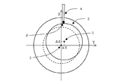
3次元座標測定方法及び装置の実施例1を説明する。図1は、3次元座標測定装置の測定部を示す図である。本実施例では、被検物はプリズムである。このプリズムは、光学面として面S1〜S3を有する。本実施例では、この3つの面の相対位置を算出する。 A first embodiment of the three-dimensional coordinate measuring method and apparatus will be described. FIG. 1 is a diagram illustrating a measuring unit of the three-dimensional coordinate measuring apparatus. In this embodiment, the test object is a prism. This prism has surfaces S1 to S3 as optical surfaces. In this embodiment, the relative positions of these three surfaces are calculated.
図1において、1は回転機構である回転ステージ、2は保持部材である基準円柱、3は回転ステージ1の回転軸、4は触針式のプローブ(以下、単にプローブ4とする。)である。また、7は固定具であり、プリズム6を基準円柱2に固定する。ここで、基準円柱2は、中心軸(回転対称軸)が、回転ステージ1の回転軸3と略一致するように設置してある。また、基準円柱2は、非常に高い真円度を有する。また、回転ステージ1は、所望の角度で停止できる構造となっている。更に、回転ステージ1には、検出素子(不図示)が内臓されている。この検出素子により、回転ステージ1が停止した時の位置(角度)を、高精度に検出できるようになっている。よって、初期位置を適当に設定しておけば、初期位置から停止位置までの、回転角を算出することが可能となっている。
In FIG. 1,
尚、本文中では、回転軸3に沿う方向をX軸方向とし、プローブ4が変位する方向をZ軸方向(本実施例では上下方向)とする。また、Y軸方向は、X軸方向とZ軸方向の両方に直交する方向である。但し、解析に用いる座標系は、これに限定するものではなく、他の座標系を用いても同様の解析が可能である。
In the text, the direction along the
面S1〜S3の形状を測定に先立って、基準円柱2の外周面を測定する。この測定には、プローブ4を用いる。このようにしておけば、基準円柱2の測定座標系と、面S1〜S3の測定座標系は同じになる。
Prior to measuring the shapes of the surfaces S 1 to S 3 , the outer peripheral surface of the
プローブ4を、基準円柱2の外周面に位置させる。この時、プローブ4をY方向に移動させて、Z方向の位置が最も高くなる位置を見つける。図1では、点Pが最も高い位置で、ここが初期位置となる。この点Pにプローブ4を接触させた状態で、回転ステージ1を回転させると、基準円柱2も回転する。ここで、回転ステージ1の回転軸3と、基準円柱の2の中心軸5が一致していると、プローブ4はZ方向に移動しない。すなわち、プローブ4からの出力信号は一定である。
The
しかしながら、実際には組み立て誤差等により、回転ステージ1の回転軸3と基準円柱2の中心軸に微妙なズレが生じる。すなわち、図2に示すように、基準円柱2の中心軸5は、回転ステージ1の回転軸3に対して、Y軸方向にΔY、Z軸方向にΔZのズレが生じる。ここで、本実施例では、回転ステージ1の回転軸3に対して、基準円柱2の中心軸5が平行にズレているとする。
However, in actuality, a slight deviation occurs between the
点Pでは、回転ステージ1の回転に伴い変位が生じる。その変位は、図2に示すように、軸ズレの量を(ΔY,ΔZ)とすると、回転ステージ1の回転角に対して、正弦波状の変位Hとなる。ここで、軸ズレの量が小さい場合、点Pにおける回転に伴う変位Hは、以下の式(1)で表記することができる。
At point P, displacement occurs as the
(1)
θ:回転ステージ回転角
R:円柱半径
図3は、回転に伴うY=0における変位Hを示したものである。ここで、基準円柱2の半径は5mmである。また、基準円柱2の中心軸5は、回転軸に対してΔY=0.02mm、ΔZ=0.03mm(θ=0°)だけ軸ズレしているとする。
(1)
θ: Rotation stage rotation angle R: Cylinder radius FIG. 3 shows a displacement H at Y = 0 accompanying rotation. Here, the radius of the
そこで、基準円柱2の外周面の測定結果からPV値及びピークとなる回転角(位相)を求めることで、軸ズレの量(ΔY,ΔZ)を求めることができる。一方、基準円柱2の半径を高精度に算出しておく。そして、軸ズレの量(ΔY,ΔZ)と基準円柱2の半径から、点PにおけるY−Z断面と回転ステージ1の回転軸3が交わる点の位置を求めることができる。
Therefore, by obtaining the PV value and the rotation angle (phase) at which the peak is obtained from the measurement result of the outer peripheral surface of the
次に、各面S1〜S3の形状測定を実施する。各面を測定する際、測定で最も高精度に測定可能なように、プローブ4 に対して各面を位置決めする。この位置決めは、回転ステージ1を回転することによって行う。本実施例の場合、プローブ4はZ軸方向(上下方向)で変位を検出する。そのため、各面がX−Y面と略水平となったところで、回転ステージ1の回転を止め、そこで固定する。
Then, a shape measurement of each surface S 1 to S 3. When measuring each surface, each surface is positioned with respect to the
図4(a)〜(c)は、各面S1〜S3の形状を測定する様子を示したものである。尚、各面上にM1〜M3で示した領域は、プローブ4で形状を測定した領域を意味する。また、この測定した領域は、各面の有効範囲を含む領域であることが望ましい。有効範囲とは、良好な像の形成に寄与する光線が通過する領域である。
4A to 4C show how the shapes of the surfaces S 1 to S 3 are measured. The area indicated by M 1 ~M 3 on each side refers to a region that was measured
図4(a)〜(c)において、面S1〜S3の測定時におけるZ軸をZ1〜Z3とし、Y軸をY1〜Y3とする。また、回転ステージ1の初期位置(例えば、回転角0度)におけるZ軸をZ0とする。そして、Z1〜Z3とZ0のな角を、それぞれθ1〜θ3とする。この、θ1〜θ3は、回転ステージ1の回転角に相当する。この回転角は、初期位置を基準としている。
4A to 4C, the Z-axis at the time of measurement of the surfaces S 1 to S 3 is Z 1 to Z 3 , and the Y-axis is Y 1 to Y 3 . Further, the Z axis at the initial position of the rotary stage 1 (for example, a rotation angle of 0 degree) is set as Z 0 . The angles between Z 1 to Z 3 and Z 0 are defined as θ 1 to θ 3 , respectively. These θ 1 to θ 3 correspond to the rotation angle of the
まず、面S1を測定するために、回転ステージ1を回転させる。図4(a)に示すように、面S1がX−Y面と略水平となったところで、回転ステージ1の回転を止める。そして、この位置における回転角θ1を高精度に検出し、記録しておく。この位置では、面S1はプローブ4に対向している。そこで、プローブ4を面S1に接触させ、測定を開始する。
First, in order to measure the surface S 1, it rotates the
面S1の測定が終了したら、プローブ4を面S1から離して、待機位置に移動させる。続いて、回転ステージ1を回転させ、図4(b)に示すように、面S2がX−Y面と略水平となったところで、回転ステージ1の回転を止める。そして、この位置における回転角θ2を高精度に検出し、記録しておく。そして、面S2に測定を行う。面S3についても同様である。
When the measurement of the surface S 1 is completed, the
測定が終了すると、測定結果として各面S1〜S3の形状データ、各面S1〜S3の測定時における回転角をθ1〜θ3が得られる。そこで、これらの測定結果から、各面S1〜S3のの相対位置を算出する。 When the measurement is completed, the shape data of each surface S 1 to S 3, the respective surfaces S 1 to S a rotational angle theta 1 through? 3 during measurement of 3 is obtained as the measurement result. Therefore, the relative positions of the surfaces S 1 to S 3 are calculated from these measurement results.
そのため、各面毎に回転ステージ1の回転軸3の位置を算出する。このとき、各面毎に基準円柱2の中心軸5の位置が異なっている。ここで、各面を測定した時の基準円柱2の中心軸5が、回転ステージ1の回転軸3に対してどのくらいずれているかは、各面S1〜S3での軸ズレの量(ΔY,ΔZ)からわかる。したがって、この軸ズレの量(ΔY,ΔZ)に基づいて、各測定における基準円柱2の中心軸5を、回転ステージ1の回転軸3に一致させる。
Therefore, the position of the
続いて、基準円柱2の中心軸5の周りに、回転の座標変換をそれぞれ実施する。上述のように、測定時、各面S1〜S3はプローブ4に対向している。そのため、測定時における面の法線の向きは、いずれもZ軸方向である。しかしながら、外径形状からわかるように、各面の法線方向は異なる。そこで、各面の法線方向が正しくなるように、回転の座標変換を行う。
Subsequently, rotation coordinate transformation is performed around the
ここでは、面S1を基準とする。面S1の測定にあたって、回転ステージ1はθ1回転している。一方、面S2の測定にあたって、回転ステージ1はθ2回転している。したがって、面1の測定から面S2の測定に移る際、ステージ1は(θ1−θ2)だけ回転していることになる。よって、面S2の測定座標に対して、X軸回りに、(θ1−θ2)量だけ、回転の座標変換を実施する。同様に、面S2の測定座標に対して、X軸回りに、(θ1−θ3)量だけ、回転の座標変換を実施する。
Here, the plane S 1 is used as a reference. In measuring the surface S 1 , the
なお、上記例では、各面の測定時に算出した基準円柱2の中心軸5を、回転ステージ1の回転軸3に、一致させるように軸を合わせた。しかしながら、例えば、回転ステージ1の回転軸3と基準円柱2の中心軸5のズレが小さい場合、どれか1つの基準円柱2の中心軸5に対して軸を合わせても良い。そのような場合も、各面S1〜S3の形状測定と共に、基準円柱2の中心軸5の算出を行う。
In the above example, the
前述のように、基準円柱2の中心軸5にはズレが存在し、各面の形状測定時毎に固定する回転ステージの位置(角度)が異なるため、このズレの量(ΔY,ΔZ)は各面S1〜S3で異なることになる。そこで、基準円柱2の中心軸5を空間的に一致させる処理を行う。ここでは、面S1を測定したときの基準円柱2の中心軸5に、残りの面S2、S3を測定したときの中心軸を合わせる処理をする。例えば、面S1を測定したときのズレを(ΔY1,ΔZ1)、面S2を測定したときのズレを(ΔY2,ΔZ2)、面S3を測定したときのズレを(ΔY3,ΔZ3)とする。
As described above, there is a deviation in the
この場合、面S1と面S2のズレは、Y軸方向で|ΔY1−ΔY2|、Z軸方向で|ΔZ1−ΔZ2|となる。よって、|ΔY1−ΔY2|及び|ΔZ1−ΔZ2|を補正量として、面S2の形状測定データに加算あるいは減算する。また、面S1と面S3のズレは、Y軸方向で|ΔY1−ΔY3|、Z軸方向で|ΔZ1−ΔZ3|となる。よって、同様に補正を行う。 In this case, the deviation between the surface S 1 and the surface S 2 is | ΔY 1 −ΔY 2 | in the Y-axis direction and | ΔZ 1 −ΔZ 2 | in the Z-axis direction. Therefore, | ΔY 1 −ΔY 2 | and | ΔZ 1 −ΔZ 2 | are added to or subtracted from the shape measurement data of the surface S 2 as correction amounts. Further, the deviation between the surface S 1 and the surface S 3 is | ΔY 1 −ΔY 3 | in the Y-axis direction and | ΔZ 1 −ΔZ 3 | in the Z-axis direction. Therefore, the correction is performed in the same manner.
以上の説明では、面S1を基準としたが、回転ステージ1の初期位置Z0を基準にしても良い。この場合、面S1にはθ1、面S2にはθ2、面S3にはθ3の量だけ、回転の座標変換を実施することになる。
In the above description, the surface S 1 is used as a reference, but the initial position Z 0 of the
図5は、回転ステージ1の基準位置におけるZ軸Z0を基準として、各被検面毎に回転の座標変換を実施した結果である。これにより、各被検面の形状測定結果を実際の形状どおりに再構成することが可能となり、面の偏心の情報を得ることが可能となる。
FIG. 5 shows a result of rotating coordinate conversion for each surface to be examined with reference to the Z axis Z 0 at the reference position of the
なお、参考までに、形状測定データを設計座標で表す方法を示す。各面の形状測定データは、面の形状に沿って走査してサンプリングした位置の点列データとなる。よって、この測定結果を基に、設計座標系の位置を求めることが可能である。 For reference, a method of expressing shape measurement data with design coordinates is shown. The shape measurement data of each surface is point sequence data of positions sampled by scanning along the shape of the surface. Therefore, it is possible to obtain the position of the design coordinate system based on this measurement result.
各面の設計座標系を算出するためには、各面毎に設計形状と測定結果を重ね合わせる。そして、そのときの残差が最小になるように、座標変換を行い、そのときのパラメータ(シフト、チルト)を最適化すればよい。この解析は、ニュートン法等の最適化手法を用いる。例えば、測定点(xi, yi)[i=1…m (測定点数m)]に対する、設計形状関数FのZ座標F(xi, yi)と、実測のZ座標zi定点数m)
F( x, y):設計形状関数
この結果、形状の測定結果と、回転軸、設計座標系の各相対位置を明確にすることが可能となる。
In order to calculate the design coordinate system of each surface, the design shape and the measurement result are overlapped for each surface. Then, coordinate conversion is performed so that the residual at that time is minimized, and the parameters (shift, tilt) at that time may be optimized. This analysis uses an optimization method such as Newton's method. For example, for the measurement point (x i , y i ) [i = 1... M (measurement point m)], the Z coordinate F (xi, yi) of the design shape function F and the actual measurement Z coordinate zi fixed point number m)
F (x, y): Design shape function As a result, it becomes possible to clarify the measurement result of the shape and the relative positions of the rotation axis and the design coordinate system.
また、設計座標系の位置を算出した際、測定結果と設計形状の差が形状誤差成分となる。従って、形状誤差成分を、例えば、多項式でフィッティングすることで、形状誤差成分を関数で近似することが可能となる。これらの解析の結果、各面の測定結果から設計座標系の位置を算出し、更に同座標系を用いて、形状を以下の関数G( x, y)で近似することが可能となる。
G( x, y):測定結果を近似した関数
F( x, y):設計形状関数
E( x, y):形状誤差成分を近似した関数
これらの解析を予め実施しておく。そして、上記解析と同様に、回転ステージ1の回転軸3の周りに、各面の測定の際に記録しておいた角度分だけ、回転の座標変換をそれぞれ実施する。このようにすることで、図6に示すように、各面の設計座標系D1〜D3と、関数で表した近似形状G1〜G3の相対位置を算出することが可能となる。
Further, when the position of the design coordinate system is calculated, the difference between the measurement result and the design shape becomes the shape error component. Therefore, the shape error component can be approximated by a function by fitting the shape error component with a polynomial, for example. As a result of these analyses, it is possible to calculate the position of the design coordinate system from the measurement results of each surface, and to approximate the shape by the following function G (x, y) using the coordinate system.
G (x, y): Function approximating measurement results
F (x, y): Design shape function
E (x, y): Function approximating shape error component These analyzes are performed in advance. Similarly to the above analysis, rotation coordinate conversion is performed around the
このように、各面の形状を関数で近似することで、定量的に、偏心量と形状誤差を求めることが可能となる。更に、偏心量と関数で近似した形状誤差を用いることで、光学性能を容易にシミュレーションすることが可能となるため、測定結果から光学性能を予想することが可能となる。 Thus, by approximating the shape of each surface with a function, the amount of eccentricity and the shape error can be obtained quantitatively. Furthermore, since the optical performance can be easily simulated by using the shape error approximated by the amount of eccentricity and the function, the optical performance can be predicted from the measurement result.
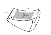
尚、設計座標系を算出する方法は、上記方法に限定されない。例えば図7にに示すように、披検物の面上に、マークm等を加工しておき、その測定結果から導出する手法をとっても良い。この場合、予め、測定に用いるマークmの位置と、設計座標系Dの相対位置を明確にしておく必要がある。 The method for calculating the design coordinate system is not limited to the above method. For example, as shown in FIG. 7, a method may be used in which the mark m or the like is processed on the surface of the specimen and is derived from the measurement result. In this case, it is necessary to clarify in advance the position of the mark m used for measurement and the relative position of the design coordinate system D.
本実施例では、回転ステージ1の回転軸に対して、基準円柱2の中心軸5が傾いている場合である。この場合は、図8に示すように、点P以外の点Q(位置)にプローブを移動させ、同様に測定を行う。よって、本実施例では、図9に示すように、点Pにおけるズレ量(ΔYP,ΔZP)と、点Qにおけるズレ量(ΔYQ,ΔZQ)が算出される。
In this embodiment, the
これより、各点におけるY-Z断面と回転軸が交わる点同士を結ぶ直線が、回転ステージ1の回転軸3となる。また、各点のであるズレ量(ΔYP,ΔZP)とズレ量(ΔYQ,ΔZQ)示すを結ぶ直線が、基準円柱2の中心軸5となる。よって、これらのズレ量から、基準円柱2の中心軸5の位置(傾きを含む)を算出することができる。
Accordingly, a straight line connecting points where the YZ cross section and the rotation axis at each point intersect becomes the
尚、測定する位置は、2点以上で実施しても構わない。このようにすれば、更に高精度に回転軸3の位置を求めることが可能となる。
In addition, you may implement the position to measure at two or more points. In this way, the position of the
基準円柱2の中心軸5の位置が求まれば、後は実施例1と同じように測定すればよい。
If the position of the
また、面の形状が平面の場合は、各面の法線ベクトルの向きを算出することが可能となる。そのため、各被検面のなす角度やピラミダル誤差を算出することが可能となる。 In addition, when the shape of the surface is a plane, the direction of the normal vector of each surface can be calculated. Therefore, it is possible to calculate an angle formed by each test surface and a pyramid error.
また、この測定はプリズムに限定するものではなく、例えばレンズであっても良い。図10は、被検物としてレンズを測定する際の様子を示したものである。この場合、回転ステージは略180度回転させて、各面毎に形状を測定する。そして、同様の解析手法をとることで、各面の形状と偏心を同時に測定することが可能となる。また、この結果、形状の相対位置が分かるため、レンズの肉厚も同様に算出することが可能となる。 Further, this measurement is not limited to the prism, and may be a lens, for example. FIG. 10 shows a state when a lens is measured as a test object. In this case, the rotary stage is rotated approximately 180 degrees and the shape is measured for each surface. And it becomes possible to measure simultaneously the shape and eccentricity of each surface by taking the same analysis method. As a result, since the relative position of the shape is known, the lens thickness can be calculated in the same manner.
尚、本測定に用いる測定機は、触針式のプローブに限定するものではなく、同測定が可能であれば、どのような手法でもよく、例えば光プローブ方式等を用いても良い。光プローブの場合、被検面に対して、非接触で測定が可能となるため、被検面に対して非破壊で測定することが可能となる。また、被検面の作用としては、測定が可能であれば、屈折面、反射面、コート面であっても良い。 Note that the measuring instrument used for this measurement is not limited to a stylus type probe, and any method may be used as long as the measurement is possible, for example, an optical probe method may be used. In the case of an optical probe, measurement can be performed in a non-contact manner on the test surface, and therefore, measurement can be performed on the test surface in a nondestructive manner. Further, the action of the test surface may be a refracting surface, a reflecting surface, or a coated surface as long as measurement is possible.
また、保持部材は基準円柱2に限られない。すなわち、保持部材の外周面をプローブで測定できれば、外形形状に制限は無い。例えば、四角柱や多角柱であっても良い。ただし、円柱であれば、外周面の測定が滑らかに行えるので、より好ましい。
Further, the holding member is not limited to the
1 回転ステージ
2 基準円柱
3 回転軸
4 触針式プローブ
5 基準円柱軸(回転対称軸)
6 被検物(プリズム)
7 固定具
8 被検物(レンズ)
S1,S2,S3 被検面
Z1,Z2,Z3 各面の形状測定時におけるZ座標軸
Z1,Z2,Z3 各面の形状測定時におけるY座標軸
Z0 回転ステージの基準位置におけるZ軸
θ1,θ2,θ3 各面の形状測定時におけるZ軸(Z1〜3)とZ0のなす角
ΔX,ΔY 回転軸に対する基準円柱の軸ズレ量
M1,M2,M3 各面の形状測定領域
D1,D2,D3,D 各面の設計座標系
G1,G2,G3 各面の測定結果を基に、関数で近似した形状
m 設計座標系算出用に加工したマーク
DESCRIPTION OF
6 Test object (prism)
7 Fixing
S1, S2, S3 Test surface
Z1, Z2, Z3 Z coordinate axes when measuring the shape of each surface
Z1, Z2, Z3 Y coordinate axis when measuring the shape of each surface
Z0 Z axis at the reference position of rotary stage θ1, θ2, θ3 Angles between Z axis (Z1-3) and Z0 when measuring the shape of each surface ΔX, ΔY Axis deviation of the reference cylinder relative to the rotary axis
M1, M2, M3 shape measurement area of each surface
D1, D2, D3, D design coordinate system of each surface
G1, G2, G3 Shape approximated by function based on measurement results on each surface
m Marks processed for design coordinate system calculation
Claims (5)
前記被検物の測定に先立って、前記保持部材を回転させて前記保持部材の外周部を測定プローブで測定し、
該測定結果から、前記回転機構の回転軸に関する情報を算出し、
前記被検物の第1面が前記測定プローブと対向するように前記保持部材を回転させ、その回転角度を第1回転角度として記憶し、
前記被検物の第1面の面形状を測定して、該第1面の面形状データを取得し、
前記被検物の第2面が前記測定プローブと対向するように前記保持部材を回転させ、その回転角度を第2回転角度として記憶し、
前記被検物の第2面の面形状を測定して、該第2面の面形状データを取得し、
前記回転機構の回転軸に関する情報、前記第1面の面形状データ、前記第2の面形状データ、前記第1の回転角度、前記第2の回転角度から、前記第1面と前記第2面の相対的な位置関係を算出することを特徴とする3次元座標測定方法。 A test object having at least two surfaces is held by a holding member connected to a rotation mechanism,
Prior to measurement of the test object, the holding member is rotated and the outer periphery of the holding member is measured with a measuring probe,
From the measurement result, information on the rotation axis of the rotation mechanism is calculated,
Rotating the holding member so that the first surface of the test object faces the measurement probe, and storing the rotation angle as a first rotation angle;
Measuring the surface shape of the first surface of the test object to obtain surface shape data of the first surface;
Rotating the holding member so that the second surface of the test object faces the measurement probe, and storing the rotation angle as a second rotation angle;
Measuring the surface shape of the second surface of the test object to obtain surface shape data of the second surface;
From the information on the rotation axis of the rotation mechanism, the surface shape data of the first surface, the second surface shape data, the first rotation angle, and the second rotation angle, the first surface and the second surface A three-dimensional coordinate measurement method characterized by calculating a relative positional relationship between
前記被検物保持する保持部材
該保持部材を回転させる回転機構、
前記回転機構に備えられ、回転角度を検出する検出素子、
前記プローブ、前記検出素子から情報に基づいて処理を行う処理装置を備え、
該処理装置は、
前記被検物の測定に先立って、前記保持部材を回転させて前記保持部材の外周部を測定し、該測定結果から前記回転機構の回転軸に関する情報を算出する過程、
前記被検物の複数の面を測定する過程、
第1面の面形状、及び第2面の面形状データを取得する過程、
前記第1面の測定時における前記検出素子からの情報、及び前記第2面の測定時における前記検出素子からの情報を取得する過程、
前記回転機構の回転軸に関する情報、前記第1面及び第2の面形状データ、前記記検出素子からの情報に基づいて、前記第1面と前記第2面の相対的な位置関係を算出する過程を備えることを特徴とする3次元座標測定装置。
A probe for measuring the shape of an object having at least two surfaces;
A holding member for holding the object to be rotated; a rotating mechanism for rotating the holding member;
A detection element provided in the rotation mechanism for detecting a rotation angle;
A processing device for performing processing based on information from the probe and the detection element;
The processor is
Prior to the measurement of the test object, the holding member is rotated to measure the outer peripheral portion of the holding member, and the information about the rotation axis of the rotation mechanism is calculated from the measurement result.
Measuring a plurality of surfaces of the specimen;
A process of acquiring surface shape data of the first surface and surface shape data of the second surface;
Obtaining information from the detection element at the time of measuring the first surface and information from the detection element at the time of measuring the second surface;
A relative positional relationship between the first surface and the second surface is calculated based on information on the rotation axis of the rotation mechanism, the first surface and second surface shape data, and information from the detection element. A three-dimensional coordinate measuring apparatus comprising a process.
Priority Applications (1)
| Application Number | Priority Date | Filing Date | Title |
|---|---|---|---|
| JP2003362473A JP2005127810A (en) | 2003-10-22 | 2003-10-22 | Three-dimensional coordinate measuring method and device |
Applications Claiming Priority (1)
| Application Number | Priority Date | Filing Date | Title |
|---|---|---|---|
| JP2003362473A JP2005127810A (en) | 2003-10-22 | 2003-10-22 | Three-dimensional coordinate measuring method and device |
Publications (2)
| Publication Number | Publication Date |
|---|---|
| JP2005127810A true JP2005127810A (en) | 2005-05-19 |
| JP2005127810A5 JP2005127810A5 (en) | 2006-11-30 |
Family
ID=34642125
Family Applications (1)
| Application Number | Title | Priority Date | Filing Date |
|---|---|---|---|
| JP2003362473A Pending JP2005127810A (en) | 2003-10-22 | 2003-10-22 | Three-dimensional coordinate measuring method and device |
Country Status (1)
| Country | Link |
|---|---|
| JP (1) | JP2005127810A (en) |
-
2003
- 2003-10-22 JP JP2003362473A patent/JP2005127810A/en active Pending
Similar Documents
| Publication | Publication Date | Title |
|---|---|---|
| WO2017107777A1 (en) | Method for measuring surface shape error of rotary symmetrical unknown aspheric surface, and measurement device thereof | |
| JP4764040B2 (en) | A method for measuring the eccentricity of the aspherical axis of a lens | |
| JP4732362B2 (en) | Method for calibrating the geometry of a multi-axis measurement system | |
| JP5399304B2 (en) | Aspherical surface measuring method and apparatus | |
| US7328125B2 (en) | Measuring method of cylindrical body | |
| JPH1183438A (en) | Position calibration method for optical measuring device | |
| KR20020092838A (en) | Profilometer and method for measuring, and method for manufacturing object of surface profiling | |
| CN110006367B (en) | Method and device for measuring yaw angle and pitch angle | |
| JP2010164388A (en) | Measuring method and measuring apparatus | |
| JPH04248409A (en) | Correcting method for error of three-dimensional measuring instrument | |
| JP2008008879A (en) | Measuring instrument, measuring reference, and precision machine tool | |
| KR20110065365A (en) | Method and apparatus for measuring aspherical body | |
| JP2000097663A (en) | Interferometer | |
| JP2008268000A (en) | Displacement measuring method and device | |
| JP2005127810A (en) | Three-dimensional coordinate measuring method and device | |
| JP4311952B2 (en) | 3D coordinate measurement method | |
| JP2005195545A (en) | Three-dimensional profile measuring method and system | |
| JP4802134B2 (en) | Posture change measuring method and apparatus | |
| JPH08233506A (en) | Method and apparatus for measuring aspherical shape and method for evaluating aspherical surface | |
| JP4922905B2 (en) | Method and apparatus for measuring position variation of rotation center line | |
| JP2892826B2 (en) | Calibration method of CMM | |
| JP2002214076A (en) | Interference measuring system, method for measuring transmission wave front and projection lens | |
| JP2001227929A (en) | Angle measuring method and apparatus | |
| KR102028699B1 (en) | Method of measuring three dimensional shape of lens and system for measuring the same | |
| JP2012002607A (en) | Conical surface measuring device |
Legal Events
| Date | Code | Title | Description |
|---|---|---|---|
| A521 | Written amendment |
Free format text: JAPANESE INTERMEDIATE CODE: A523 Effective date: 20061018 |
|
| A621 | Written request for application examination |
Free format text: JAPANESE INTERMEDIATE CODE: A621 Effective date: 20061018 |
|
| A977 | Report on retrieval |
Free format text: JAPANESE INTERMEDIATE CODE: A971007 Effective date: 20090424 |
|
| A131 | Notification of reasons for refusal |
Free format text: JAPANESE INTERMEDIATE CODE: A131 Effective date: 20090512 |
|
| A02 | Decision of refusal |
Free format text: JAPANESE INTERMEDIATE CODE: A02 Effective date: 20091027 |