JP2005123783A - Encoding apparatus and encoding method - Google Patents
Encoding apparatus and encoding method Download PDFInfo
- Publication number
- JP2005123783A JP2005123783A JP2003354886A JP2003354886A JP2005123783A JP 2005123783 A JP2005123783 A JP 2005123783A JP 2003354886 A JP2003354886 A JP 2003354886A JP 2003354886 A JP2003354886 A JP 2003354886A JP 2005123783 A JP2005123783 A JP 2005123783A
- Authority
- JP
- Japan
- Prior art keywords
- block
- dct
- prediction
- quantized
- component
- Prior art date
- Legal status (The legal status is an assumption and is not a legal conclusion. Google has not performed a legal analysis and makes no representation as to the accuracy of the status listed.)
- Pending
Links
Images


Landscapes
- Compression Or Coding Systems Of Tv Signals (AREA)
Abstract
【課題】処理サイクルの少ない高速な符号化エンコードの実現
【解決手段】量子化された量子化離散コサイン変換係数(量子化DCT係数)を記憶する第1の記憶手段(量子化係数バッファ)においては、マクロブロックを構成するn個のブロックに対して(n+1)個以上の記憶領域(DC/AC-Bank)を設け、この記憶領域が順次用いられることで第1の記憶手段がリングバッファとして使用できるようにする。また、各ブロックについてのAC成分予測誤差(AC予測値)を記憶する第2の記憶手段(AC予測値バッファ)も備えるようにし、さらにその第2の記憶手段についても(n+1)個以上の記憶領域(AC-Bank)を設け、この記憶領域が順次用いられることで第2の記憶手段もリングバッファとして使用できるようにする。その上で、或るブロックの量子化離散コサイン変換係数を上記第1の記憶手段に記憶させる期間において、該ブロックについてのAC成分予測誤差演算を行い、上記第2の記憶手段に記憶させる処理を行う。
【選択図】 図3
In a first storage means (quantization coefficient buffer) for storing quantized quantized discrete cosine transform coefficients (quantized DCT coefficients). , (N + 1) or more storage areas (DC / AC-Bank) are provided for n blocks constituting a macroblock, and the first storage means is used as a ring buffer by sequentially using these storage areas It can be so. Further, a second storage unit (AC predicted value buffer) for storing an AC component prediction error (AC predicted value) for each block is provided, and the second storage unit also stores (n + 1) or more memories. An area (AC-Bank) is provided, and this storage area is sequentially used so that the second storage means can also be used as a ring buffer. In addition, in a period in which the quantized discrete cosine transform coefficient of a certain block is stored in the first storage unit, an AC component prediction error calculation for the block is performed and stored in the second storage unit. Do.
[Selection] Figure 3
Description
本発明は、符号化装置及び符号化方法に関し、特に、動画像データを光磁気ディスクや磁気テープ等の記録媒体に記録したり、テレビ会議システム、テレビ電話システム、放送用機器、マルチメディアデータベース検索システム等のように伝送路を介して送信側から受信側に動画像データを伝送する機器などにおいて好適な符号化装置及び符号化方法に関する。 The present invention relates to an encoding device and an encoding method, and in particular, records moving image data on a recording medium such as a magneto-optical disk or a magnetic tape, or a video conference system, a video phone system, a broadcasting device, or a multimedia database search. The present invention relates to an encoding apparatus and an encoding method suitable for a device that transmits moving image data from a transmission side to a reception side via a transmission line such as a system.
例えば、テレビ会議システム、テレビ電話システム等のように動画像データを伝送するシステムでは、伝送路を効率よく利用するために、画像のライン相関やフレーム間相関を利用して画像データを圧縮符号化している。
動画像の高能率符号化方式には、代表的なものとしてMPEG(Moving Picture Experts Group)方式がある。MPEG方式は、蓄積用動画像符号化方式である。これは、ISO−IEC/JTC1/SC2/WG11において議論され、標準案として提案されたものであり、動き補償予測符号化とDCT(Discrete Cosine Transform)符号化を組み合わせたハイブリッド方式が採用されている。
MPEGでは、様々なアプリケーションや機能に対応するために、幾つかのプロファイル及びレベルが定義されている。最も基本的なものがメインプロファイルレベル(MP @ML:Main Profile at Main Level)である。
For example, in a system for transmitting moving image data such as a video conference system and a videophone system, the image data is compressed and encoded using line correlation or interframe correlation of the image in order to efficiently use the transmission path. ing.
A representative example of a high-efficiency encoding method for moving images is the Moving Picture Experts Group (MPEG) method. The MPEG system is a moving image encoding system for storage. This was discussed in ISO-IEC / JTC1 / SC2 / WG11 and proposed as a standard proposal, and a hybrid method combining motion compensation prediction coding and DCT (Discrete Cosine Transform) coding is adopted. .
In MPEG, several profiles and levels are defined to support various applications and functions. The most basic one is the main profile level (MP @ML: Main Profile at Main Level).
また現在では、画像を構成する物体(オブジェクト)毎のシーケンスであるビデオオブジェクト(VO:Video Object)単位で符号化を行うMPEG4方式がISO−IEC/JTC1/SC29/WG11において標準化されている。
MPEG4方式は、従来の映像/オーディオ信号の圧縮符号化に加え、静止画、CG(コンピュータグラフィクス)画像、分析合成系の音声符号化、MIDI(Musical Instrument Data Interface)等による合成オーディオやテキストも含めた総合マルチメディアの符号化規格を目指したものである。
At present, the MPEG4 system that performs coding in units of video objects (VO), which are sequences of objects (objects) constituting an image, is standardized in ISO-IEC / JTC1 / SC29 / WG11.
In addition to conventional video / audio signal compression coding, the MPEG4 system includes still images, CG (computer graphics) images, analysis / synthesis audio coding, MIDI (Musical Instrument Data Interface), and other synthesized audio and text. It aims to be a comprehensive multimedia coding standard.
MPEG4方式では、基本的に符号化/復号化できる画像として、4:2:0フォーマットとよばれる画像フォーマットのみが規定されている。
この4:2:0フォーマットは、輝度Yの走査2本、水平方向の2画素に対して、色差Cr、Cbがそれぞれ1画素ずつで割り当てられる画像フォーマット(すなわち、輝度Yの4画素に対して色差Cr、Cbがそれぞれ1画素ずつ割り当てられる。)であり、その色差Cr、Cbの位置は、輝度Yに対して同位置に存在する。
4:2:0フォーマットのブロックは、輝度又は色差毎の隣り合った、例えば8画素×8ラインから構成される。DCT(離散コサイン変換)は、この単位で実行される。マクロブロックは、例えば、画像フォーマットがいわゆる4:2:0コンポーネントディジタル信号である場合、上下左右に隣り合った4つの輝度Yのブロックと、画像上では同じ位置に当たる色差Cb、Crそれぞれのブロック全部で6つのブロックで構成される。すなわち、MPEG4方式では、4:2:0フォーマットのマクロブロックが符号化復号画像として定義されている。
MPEG4方式の画像符号化におけるDCT係数の差分値の算出方法は、本願出願人等によって開示されている(例えば、上記特許文献1参照)。
In the MPEG4 system, only an image format called 4: 2: 0 format is defined as an image that can be basically encoded / decoded.
This 4: 2: 0 format is an image format in which color differences Cr and Cb are assigned to one pixel each for two pixels of luminance Y and two horizontal pixels (that is, for four pixels of luminance Y). The color differences Cr and Cb are assigned to one pixel each.), And the positions of the color differences Cr and Cb are at the same position with respect to the luminance Y.
A block in 4: 2: 0 format is composed of adjacent, for example, 8 pixels × 8 lines for each luminance or color difference. DCT (Discrete Cosine Transform) is performed in this unit. For example, when the image format is a so-called 4: 2: 0 component digital signal, the four luminance Y blocks adjacent vertically and horizontally, and all blocks of the color differences Cb and Cr corresponding to the same position on the image, respectively. It consists of 6 blocks. That is, in the MPEG4 system, a macro block of 4: 2: 0 format is defined as an encoded decoded image.
A method for calculating a difference value of a DCT coefficient in MPEG4 image coding has been disclosed by the applicant of the present application and the like (see, for example,
公知の通り、MPEG2ではイントラブロックのDC成分だけを差分符号化するが、MPEG4では量子化されたDC成分とAC成分の両方に対して適応的に予測符号化することによってイントラブロックの符号化効率の改善を図っている。
DC成分の予測値は、対象となるブロックの周辺に隣接するブロック間の水平および垂直方向のDC成分の勾配によって適応的に選択される。
As is well known, only the DC component of the intra block is differentially encoded in MPEG2, but in MPEG4, the coding efficiency of the intra block is adaptively encoded by predictive encoding of both the quantized DC component and AC component. We are trying to improve.
The predicted value of the DC component is adaptively selected according to the gradient of the DC component in the horizontal and vertical directions between adjacent blocks around the target block.
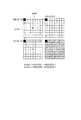
図7は対象となるブロックXと、その周辺においてそれぞれ左、左上、上の各方向に隣接するブロックA,B,Cを示している。各ブロックの格子はDCT係数を表す。
図示するようにブロックAのDCT係数FA[0][0]、ブロックBのDCT係数FB[0][0]、ブロックCのDCT係数FC[0][0]を考える。これらの値は逆量子化されたDCT係数値であり、これらの値を用いてブロックXのDC成分に対する予測値δpを式1により決定する。
[式1]
if (|FA[0][0]−FB[0][0]|<|FB[0][0]−FC[0][0]|)
δp = FC[0][0]
else
δp = FA[0][0]
FIG. 7 shows a target block X and blocks A, B, and C adjacent to each other in the left, upper left, and upper directions in the vicinity thereof. Each block grid represents a DCT coefficient.
As illustrated, the DCT coefficient FA [0] [0] of the block A, the DCT coefficient FB [0] [0] of the block B, and the DCT coefficient FC [0] [0] of the block C are considered. These values are dequantized DCT coefficient values, and the predicted value δp for the DC component of the block X is determined by
[Formula 1]
if (| FA [0] [0] −FB [0] [0] | <| FB [0] [0] −FC [0] [0] |)
δp = FC [0] [0]
else
δp = FA [0] [0]
この式は、FA[0][0]とFB[0][0]の差の絶対値(ΔVS)と、FB[0][0]とFC[0][0]の差の絶対値(ΔHS)とを比較し、FA[0][0]とFB[0][0]の差の絶対値(ΔVS)の方が小さい場合には、縦方向に相関が強いので、ブロックXに対してブロックCを予測ブロックとし、一方、FB[0][0]とFC[0][0]の差の絶対値(ΔHS)の方が小さい場合には、横方向の相関が強いのでブロックXに対してブロックAを予測ブロックとして予測値δpを決定することを表している。 This formula shows the absolute value (ΔVS) of the difference between FA [0] [0] and FB [0] [0] and the absolute value of the difference between FB [0] [0] and FC [0] [0] ( ΔHS), and if the absolute value (ΔVS) of the difference between FA [0] [0] and FB [0] [0] is smaller, the correlation is stronger in the vertical direction. Block C as a prediction block, on the other hand, if the absolute value (ΔHS) of the difference between FB [0] [0] and FC [0] [0] is smaller, the correlation in the horizontal direction is strong, so block X Represents that the prediction value δp is determined with the block A as the prediction block.
このようにして決定した予測値を用いて次の式2のように予測誤差Δxを求める。
[式2]
Δx = δx−δp /dc_scaler
ここでδxはブロックXの量子化されたDC成分、dc_scalerはブロックXの量子化ステップである。予測誤差ΔxはMPEG2と同じ方法で可変長符号化する。
Using the predicted value determined in this way, a prediction error Δx is obtained as in the following
[Formula 2]
Δx = δx−δp / dc_scaler
Here, δx is a quantized DC component of the block X, and dc_scaler is a quantization step of the block X. The prediction error Δx is variable length encoded by the same method as MPEG2.
AC成分の予測は、DC成分予測で決定したブロックを参照して行う。すなわち、ブロックAを用いてDC成分を予測する場合、図8(b)のように、ブロックAの垂直第一列のAC係数を予測値とする。また、ブロックCを用いてDC成分を予測場合、図8(a)のようにブロックCの水平第一行のAC係数を予測値とする。 The prediction of the AC component is performed with reference to the block determined by the DC component prediction. That is, when the DC component is predicted using the block A, the AC coefficient of the vertical first column of the block A is used as the predicted value as shown in FIG. Further, when the DC component is predicted using the block C, the AC coefficient of the horizontal first row of the block C is used as the predicted value as shown in FIG.
ところでAC成分の予測誤差は、予測しないAC成分より値が大きい場合がある。そのためマクロブロック毎に1ビットのフラグを使って、AC成分予測を有効または無効にすることが出来るようにされている。即ち、マクロブロックに含まれるすべてのブロック成分について予測前のAC成分(第一列または第一行)の絶対値和と、AC成分の予測誤差の絶対値和を比較し、予測誤差の絶対値和が予測前の絶対値和より小さい場合を有効とする。
ところがこのため、AC成分予測はマクロブロック内のすべてのブロックをAC予測し、絶対値和を比較するまでは次のステップである可変長符号化には移れない。また可変長符号化ブロックがバッファ内のDCT係数を読み出す前に、次のマクロブロックのDCT係数を書き込むことは出来ない。したがって、パイプライン処理を行うことが難しく、トータルでの処理サイクル数が増大してしまう。
このことを図9、図10、図11を用いて説明する。
By the way, the AC component prediction error may be larger than the unpredicted AC component. Therefore, AC component prediction can be made valid or invalid by using a 1-bit flag for each macroblock. That is, for all block components included in the macroblock, the absolute value sum of the AC component (first column or first row) before prediction and the absolute value sum of the prediction error of the AC component are compared, and the absolute value of the prediction error is compared. Valid when the sum is less than the sum of absolute values before prediction.
However, AC component prediction cannot be shifted to the next step, variable-length coding, until all blocks in the macroblock are AC-predicted and absolute value sums are compared. Also, the DCT coefficient of the next macroblock cannot be written before the variable length coding block reads the DCT coefficient in the buffer. Therefore, it is difficult to perform pipeline processing, and the total number of processing cycles increases.
This will be described with reference to FIG. 9, FIG. 10, and FIG.
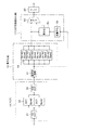
まず図9では、一般的なMPEG4の符号化装置1の構成例を説明する。これは入力した画像データをMPEG4方式、H.263等の規格に準拠した方式で符号化できるエンコーダであり、この符号化装置1で符号化して得られたビットストリームは、多重化されて、例えば、地上波や衛星回線、CATV網等の伝送路を介して伝送される。或いは、磁気ディスク、光磁気ディスク、光ディスク、磁気テープ、その他の記録媒体に記録される。
First, a configuration example of a general
符号化すべき入力画像信号(動画像データ)は、まず、前画像処理部11に入力される。前画像処理部11は、図示しないが、VO(Video Object)構成部とVOP(Video Object Plane)構成部とを有し、入力される画像を構成するオブジェクト毎に、このシーケンスであるVOを構成し、VOPを構成している。
MPEG4では、自然画像をVOと呼んでいる。VOには矩形形状のVOと任意形状のVOがある。そしてVOは所定の時刻で撮像した複数のVOPから構成される。このVOPがMPEG4で扱う映像データの基本単位である。矩形形状の場合、VOPはMPEG1やMPEG2のフレーム又はフィールドに相当する。
An input image signal (moving image data) to be encoded is first input to the previous
In MPEG4, a natural image is called VO. The VO includes a rectangular VO and an arbitrary VO. A VO is composed of a plurality of VOPs imaged at a predetermined time. This VOP is a basic unit of video data handled by MPEG4. In the case of a rectangular shape, the VOP corresponds to an MPEG1 or MPEG2 frame or field.
前画像処理部11では、具体的には、例えば、符号化すべき画像データが独立した背景のシーケンスと前景のシーケンスとから構成されている場合、VO構成部は、例えば、背景のシーケンスをVO1としてVOP構成部に出力するとともに前景のシーケンスをVO2としてVOP構成部に出力する。
VO構成部は、符号化すべき画像データが、例えば背景と前景とが既に合成されたものである場合、所定のアルゴリズムにしたがって、この画像を領域分割することにより、背景と前景とを取り出し、それぞれのシーケンスとしてのVOを対応するVOP構成部に出力する。
VOP構成部は、VO構成部で出力された各フレームからオブジェクトを抽出し、この抽出されたオブジェクト(物体)を囲む最小の長方形をVOPとする。このとき、VOP構成部では、横及び縦の画素数が16の倍数になるようにVOPを構成する。VOP構成部は、このVOPを後段の動き検出、動き補償、DCT回路等に供給する。また、VOP構成部は、VOPの大きさ(例えば、横及び縦の長さ)を表すサイズデータ(VOP_size)と、フレームにおけるVOPの位置(例えば、フレームの最も左上を原点とするときの座標)を表すオフセットデータ(VOP_offset)とを検出し、これらのデータも後段の各回路に供給する。
Specifically, in the fore
When the image data to be encoded is, for example, the background and the foreground already synthesized, the VO configuration unit extracts the background and the foreground by dividing the image into regions according to a predetermined algorithm. Is output to the corresponding VOP configuration unit.
The VOP configuration unit extracts an object from each frame output by the VO configuration unit, and sets a minimum rectangle surrounding the extracted object (object) as a VOP. At this time, the VOP configuration unit configures the VOP so that the number of horizontal and vertical pixels is a multiple of 16. The VOP configuration unit supplies this VOP to the subsequent motion detection, motion compensation, DCT circuit, and the like. In addition, the VOP configuration unit includes size data (VOP_size) representing the size (for example, horizontal and vertical lengths) of the VOP, and the position of the VOP in the frame (for example, coordinates when the uppermost left of the frame is the origin) Offset data (VOP_offset) is detected, and these data are also supplied to subsequent circuits.
入力画像信号(動画像データ)は、フレームメモリ12に供給されて、VOPとして記憶される。
動き検出及び動き補償部13では、フレームメモリ12に記憶されたVOPに対してマクロブロック単位で動きベクトルを検出する。すなわち、上述したように、VOPは時刻(フレーム)によって大きさや位置が変化するため、この動きベクトルの検出に当たっては、検出のための基準となる座標系を設定し、座標系における動きを検出する必要がある。そこで、動き検出及び動き補償部13では、上述の絶対座標系を基準座標系とし、サイズデータ(FSZ_B)及びオフセットデータ(FPOS_B)にしたがって、この絶対座標系に符号化対象のVOP及び参照画像とするVOPを配置して動きベクトルを検出する。
なお、検出された動きベクトル(MV)は、予測モードとともに後段のVLC器22、量子化器16、逆量子化器18、DCT係数差分化器17等に供給される。
The input image signal (moving image data) is supplied to the
The motion detection and
The detected motion vector (MV) is supplied to the
演算器14には、動き検出及び動き補償部13によってフレームメモリ12から読み出された画像データと同一のマクロブロックデータが供給される。演算器14では、マクロブロックと動き検出及び動き補償部13での予測画像との差分を演算する。
この差分値は、DCT器15に送られる。
動き検出及び動き補償部13は、予測モードがイントラ符号化モードである場合には予測画像を出力しない。この場合、演算器14は、特に処理を行わず、フレームメモリ12から読み出したマクロブロックデータをそのままDCT器15に出力する。
The
This difference value is sent to the
The motion detection and
DCT器15は、演算器14の出力データに対して、8画素×8ラインからなるブロック単位でDCT処理を施し、このDCT処理の結果得られるDCT係数を量子化器16に供給する。
量子化器16は、入力されたDCT係数を量子化する。即ちDCT器15で得られた係数を或る値で割算して小さい値の係数で表現することによって符号化量を減らす処理を行う。そしてこの量子化処理で得られた量子化データをDCT係数差分化器17及び逆量子化器18に送る。
The
The
逆量子化器18は、量子化器16から入力された8画素×8ラインの量子化されたDCT係数を量子化し、IDCT器19に送る。
IDCT器19は、逆量子化器18より逆量子化されたDCT係数を受け取り、IDCT処理して演算器20に出力する。
The inverse quantizer 18 quantizes the 8-pixel × 8-line quantized DCT coefficient input from the
The
演算器20には、IDCT器19の出力データのほか、動き検出及び動き補償部13から演算器14に供給されている予測画像と同一のデータが供給されている。演算器20は、IDCT器19から出力される予測残差(差分データ)と、動き検出及び動き補償部13からの予測画像データとを加算することで、もとの画像データを局所復号し、この局所復号した画像データ(以下、局所復号画像データと記す。)を出力する。ただし、予測モードがイントラ符号化である場合、IDCT器19の出力データは、演算器20をスルーして、そのまま局所復号画像データとしてフレームメモリ21に供給される。この復号画像データは、受信側で得られる復号画像データと同一である。
In addition to the output data of the
なお、この画像信号処理装置1では、MPEG4方式の場合、演算器20において得られた局所復号画像データは、テキスチャ(texture)情報としてパディング処理される。一方、形状情報(キー信号)、入力されたサイズデータ(FSZ_B)、オフセットデータ(FPOS_B)、VOPのサイズデータ(VOP_size)、OPのオフセットデータ(VOP_offset)及び動きベクトル検出器102より出力された動きベクトルと予測モードは、MPEG4方式のビジュアルコミッティドラフト(Visual Committe draft)にある記述にしたがって、この形状情報の符号化に用いられる。符号化された形状情報は、局所復号化され、局所復号化されたデータは、色差情報作成及びパディング処理に用いられるほか、DCT係数差分化器17、VLC器22へ送られる。
In the image
上述したように、入力された画像データは、フレームメモリ12に格納され、基本単位である16画素×16ラインからなるマクロブロックに分割され処理される。
MPEG4方式では4:2:0フォーマットのみが規定されているが、この4:2:0フォーマットでは、1マクロブロックは、8ライン×8画素で構成されるブロックとして、4つの輝度成分のブロックY0,Y1,Y2,Y3と、2つの色差成分のブロックCb、Crとで構成されている。
このようなマクロブロックに対し、離散コサイン変換を施して量子化する。量子化されたDCT係数にVLC(Variable Length Code)とよばれる可変長符号化を施す。これがイントラ符号化である。
一方、符号化の対象となるピクチャに対して、時間的に隣接する別のピクチャから動き検出とよばれる方法でブロックマッチングが最も小さい予測ブロックを取得し、この予測ブロックと参照マクロブロック(カレントマクロブロック)との差分を求め、この差分値に対してDCT、量子化、可変長符号化を行う。これがインター符号化である。
特に、MPEG4方式では、DCT係数差分化器17でイントラ符号化を行う際、上記図7,図8で説明したように、DCT係数のDC成分及び一部のAC成分に対して予測を行い、そのDCT係数の差分値を符号化し効率の改善を図っている。
As described above, the input image data is stored in the
In the MPEG4 system, only the 4: 2: 0 format is defined, but in this 4: 2: 0 format, one macroblock is a block composed of 8 lines × 8 pixels, and four luminance component blocks Y0. , Y1, Y2, and Y3, and two color difference component blocks Cb and Cr.
Such macroblocks are quantized by performing a discrete cosine transform. Variable length coding called VLC (Variable Length Code) is applied to the quantized DCT coefficient. This is intra coding.
On the other hand, for a picture to be encoded, a prediction block having the smallest block matching is obtained from another temporally adjacent picture by a method called motion detection, and this prediction block and a reference macroblock (current macro) are obtained. A difference from the block) is obtained, and DCT, quantization, and variable length coding are performed on the difference value. This is inter coding.
In particular, in the MPEG4 system, when the intra coding is performed by the
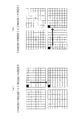
図10は、DCT器15,量子化器16、DCT係数差分化器17の構成をより詳しく示したものである。また図11には図10の構成によって行われる処理タイミングを示している。
図9に示した演算器14から図10のDCT器15には、1マクロブロックにつき、ブロックY0,Y1,Y2,Y3,Cb,Crが順次入力され2次元(水平及び垂直)DCT処理される。即ちこれらのブロックは1stDCT部31で処理された後、バッファ32(DCT Bank0、DCT Bank1)にバッファリングされ、さらに2ndDCT部33で処理される。
例えば図11に示すように、タイミングT1では、入力されたブロックY0が1stDCT処理され、DCT Bank0に書き込まれる。次にタイミングT2では、入力されたブロックY1が1stDCT処理され、DCT Bank1に書き込まれる。このときDCT Bank0からはブロックY0が読み出され、2ndDCT処理される。さらに次にタイミングT3では、入力されたブロックY2が1stDCT処理され、DCT Bank0に書き込まれる。このときDCT Bank1からはブロックY1が読み出され、2ndDCT処理される。バッファ32のDCT Bank0、DCT Bank1は、このように交互に使用される。
FIG. 10 shows the configuration of the
Blocks Y0, Y1, Y2, Y3, Cb, and Cr are sequentially input to one macroblock from the
For example, as shown in FIG. 11, at the timing T1, the input block Y0 is subjected to 1st DCT processing and written to DCT Bank0. Next, at timing T2, the input block Y1 is subjected to 1st DCT processing and written to DCT Bank1. At this time, the block Y0 is read from the DCT Bank0 and subjected to 2ndDCT processing. Next, at timing T3, the input block Y2 is subjected to 1st DCT processing and written to DCT Bank0. At this time, the block Y1 is read from the DCT Bank1 and subjected to 2ndDCT processing. The DCT Bank0 and DCT Bank1 of the
DCT器15の出力は量子化器16において、量子化回路41で量子化され、量子化係数バッファ42にバッファリングされる。量子化係数バッファ42には、1マクロブロック分のバッファリングを行うため、6つのブロックにそれぞれ対応するDC/AC-Bank0〜DC/AC-Bank5が設けられている。量子化された各ブロックのDCT係数は、それぞれDC/AC-Bank0〜DC/AC-Bank5に格納される。
即ち図11のタイミングT2では、ブロックY0が2ndDCT処理された後、ブロックを構成する64個のDCT係数が量子化されるが、量子化処理された各DCT係数がDC/AC-Bank0に書き込まれていくことになる。なお、図11において「WR」は量子化係数バッファ42への書込、「RD」は量子化係数バッファ42からの読出を示している。
またタイミングT3では、量子化回路41は2ndDCT処理された後のブロックY1のデータの量子化を行うことになり、この場合、量子化処理された各DCT係数はDC/AC-Bank1に書き込まれていく。
以降同様に、各ブロックY2、Y3、Cb、Crが、図示するように順次処理され、それらの量子化されたDCT係数が、DC/AC-Bank2、DC/AC-Bank3、DC/AC-Bank4、DC/AC-Bank5に書き込まれていくことになる。
The output of the
That is, at the timing T2 in FIG. 11, after the block Y0 is subjected to the 2nd DCT process, the 64 DCT coefficients constituting the block are quantized, but each of the quantized DCT coefficients is written to DC / AC-Bank0. It will follow. In FIG. 11, “WR” indicates writing to the
At timing T3, the quantizing
Thereafter, similarly, each block Y2, Y3, Cb, Cr is sequentially processed as shown in the figure, and the quantized DCT coefficients are obtained as DC / AC-Bank2, DC / AC-Bank3, DC / AC-Bank4. Will be written to DC / AC-Bank5.
タイミングT8においては、1マクロブロックを構成する各ブロックのDCT係数が量子化係数バッファ42のDC/AC-Bank0〜DC/AC-Bank5に確保された状態となる。
そこでタイミングT8においては、t1期間においてDC/AC-Bank0〜DC/AC-Bank5に確保された量子化DCT係数値が読み出されてDCT係数差分化器17の差分化回路51に供給される。差分化回路51では、逆量子化回路53によって得られるDCT係数値を用いて、図11のt2期間において予測演算及び予測方向の決定が行われる。
つまり上述したように予測ブロックの決定、DC成分及びAC成分の予測誤差の算出、さらにはAC成分予測の有効/無効判別を行うものとなる。
At timing T8, the DCT coefficient of each block constituting one macroblock is secured in DC / AC-
Therefore, at the timing T8, the quantized DCT coefficient values secured in the DC / AC-
That is, as described above, prediction block determination, DC component and AC component prediction error calculation, and AC component prediction validity / invalidity determination are performed.
ここで、このような処理をt2期間に行うのは、上述のように、AC成分予測の有効/無効判別が、マクロブロックに含まれるすべてのブロック成分について予測前のAC成分(第一列または第一行)の絶対値和と、AC成分の予測誤差の絶対値和を比較して行われるためである。換言すれば、AC成分予測の有効/無効判別は、1マクロブロックを構成する各ブロックのDCT係数が量子化係数バッファ42のDC/AC-Bank0〜DC/AC-Bank5に確保された状態となった時点で可能となるためである。
そして、AC成分予測の有効/無効判別結果に応じて、各ブロックのデータがVLC器22に供給され、可変長符号化される。
例えばタイミングT9においては、もしAC成分予測が有効とされれば、ブロックY0の64個のデータのうちに、差分化回路51で算出されたAC成分の予測誤差としての7個のデータが含まれることになるように、量子化係数バッファ42のDC/AC-Bank0からの出力と差分化回路51の出力がマルチプレクサ52によって順次選択されてVLC器22に供給され、可変長符号化される。もしAC成分予測が無効とされれば、差分化回路51で算出されたAC成分の予測誤差は用いられず、マルチプレクサ52によってDC/AC-Bank0から読み出されるデータ、即ち予測しないAC成分のデータが選択されて、VLC器22で可変長符号化されることになる。
Here, such a process is performed in the period t2, because, as described above, the AC component prediction validity / invalidity determination is performed for all block components included in the macroblock before the AC component (first column or This is because the absolute value sum in the first line) is compared with the absolute value sum of the AC component prediction error. In other words, the validity / invalidity determination of the AC component prediction is in a state where the DCT coefficients of each block constituting one macroblock are secured in DC / AC-
Then, the data of each block is supplied to the
For example, at the timing T9, if AC component prediction is enabled, seven pieces of data as prediction errors of the AC component calculated by the differentiating
また図示するように、タイミングT10では、ブロックY1についてDC/AC-Bank1から読み出されるデータと、差分化回路51で算出されたDC成分及びAC成分の予測誤差とが、AC成分予測の有効/無効判別結果に応じて選択され、VLC器22に供給される。同様にタイミングT11,T12・・・では、順次ブロックY2,Y3,Cb,Crについて処理される。
Further, as shown in the figure, at timing T10, the data read from the DC / AC-
ここで、この一連の処理を考えた場合、次のマクロブロックのDCT処理は、タイミングT9から開始しなければならないことになる。タイミングT9では、1stDCT処理として、次のマクロブロックの先頭ブロックY0の処理が行われることを実線で示している。タイミングT9から次のマクロブロックの処理を開始しなければならないのは、もし破線で示すようにタイミングT8から開始させると、量子化係数バッファ42にオーバーライトが発生する可能性があるためである。
タイミングT8で次のマクロブロックのブロックY0のDCT処理を開始したと仮定すると、そのブロックY0の量子化DCT係数を量子化係数バッファ42のDC/AC-Bank0に書き込むのは、これも破線で示すようにタイミングT9〜T10の間の期間となる。
ところがタイミングT9からは、先のマクロブロックのブロックY0の量子化DCT係数をDC/AC-Bank0から読み出してVLC器22に転送している。
このためDC/AC-Bank0において、先のマクロブロックのブロックY0の量子化DCT係数が読み出される前に、次のマクロブロックのブロックY0の量子化DCT係数が書き込まれてしまう危険性がある。
特にこれは、可変長符号化の量子化DCT係数の読み出しは、ジグザグスキャン、垂直スキャン、水平スキャンなどスキャン方法が変わると読み出し順序が変わり、これによってまだ読み出されていない量子化DCT係数の記憶領域に、新たな量子化DCT係数が書き込まれる可能性が生ずるためである。
従ってこれを避けるためには、タイミングT9から次のマクロブロックのDCT処理を開始しなければならない。
Here, when considering this series of processing, the DCT processing of the next macroblock must be started from timing T9. At timing T9, a solid line indicates that the first block Y0 of the next macroblock is processed as the 1st DCT process. The reason for starting processing of the next macroblock from timing T9 is that if it is started from timing T8 as indicated by a broken line, there is a possibility that the
Assuming that the DCT processing of the block Y0 of the next macroblock is started at the timing T8, writing the quantized DCT coefficient of the block Y0 to the DC / AC-Bank0 of the quantized
However, from timing T9, the quantized DCT coefficient of block Y0 of the previous macroblock is read from DC / AC-Bank0 and transferred to the
Therefore, in DC / AC-
In particular, this is because the variable DC coding coefficient DCT coefficients are read out when the scanning method such as zigzag scanning, vertical scanning, and horizontal scanning changes, thereby storing the quantized DCT coefficients that have not yet been read out. This is because a new quantized DCT coefficient may be written in the area.
Therefore, in order to avoid this, it is necessary to start DCT processing of the next macroblock from timing T9.
以上のことが、上記一連の処理についてパイプライン処理を行うことが難しい事情である。
即ち、第1の理由としては、AC成分予測の有効/無効判別が、1マクロブロックを構成する各ブロックのDCT係数が量子化係数バッファ42のDC/AC-Bank0〜DC/AC-Bank5に確保された状態となった時点で可能となるため、タイミングT8から予測ブロックの決定、DC成分及びAC成分の予測誤差の算出、さらにはAC成分予測の有効/無効判別を行うことと、第2の理由としては量子化係数バッファ42のオーバライトの危険性を回避する必要があることであり、これらの理由により上記タイミングT7〜T9として期間のロスが生ずることになる。
これによってパイプライン処理が妨げられ、またトータルでの処理サイクル数が増大してしまい、効率の良い処理ができないものとなっている。
The above is the situation in which it is difficult to perform pipeline processing for the above series of processing.
That is, the first reason is that the AC component prediction validity / invalidity determination is ensured in the DC / AC-
This hinders pipeline processing and increases the total number of processing cycles, making it impossible to perform efficient processing.
本発明は上記の点に鑑みて、DCTから可変長符号化までのパイプライン処理を実現し、処理の効率化を図ることを目的とする。 An object of the present invention is to realize pipeline processing from DCT to variable-length coding in view of the above points, and to improve processing efficiency.
このため本発明では、輝度成分及び色差成分から構成されるn個のブロックによってマクロブロックが形成される画像データに対して、離散コサイン変換、離散コサイン変換係数の量子化、及び可変長符号化を行う符号化装置において、(n+1)個以上の記憶領域が設けられ、各記憶領域へ各ブロックの量子化離散コサイン変換係数が順次格納される第1の記憶手段と、(n+1)個以上の記憶領域が設けられ、各記憶領域へ各ブロックのAC成分予測誤差が順次格納される第2の記憶手段と、或るブロックの量子化離散コサイン変換係数を上記第1の記憶手段に記憶させる期間において、該ブロックについてのAC成分予測誤差演算を行い、上記第2の記憶手段に算出された該AC成分予測誤差を記憶させるAC予測演算手段と、上記マクロブロックに含まれる全ブロックのAC成分予測誤差を用いて該AC成分予測の有効/無効を判別し、上記可変長符号化処理に供する上記量子化離散コサイン変換係数及び上記AC成分予測誤差を、該判別結果に基づいて上記第1,第2の記憶手段から読み出す読出制御手段とを備える。 For this reason, in the present invention, discrete cosine transform, discrete cosine transform coefficient quantization, and variable length coding are performed on image data in which a macroblock is formed by n blocks composed of luminance components and color difference components. In the encoding apparatus, (n + 1) or more storage areas are provided, first storage means for sequentially storing the quantized discrete cosine transform coefficients of each block in each storage area, and (n + 1) or more storages A second storage unit in which an AC component prediction error of each block is sequentially stored in each storage region, and a period in which the quantized discrete cosine transform coefficient of a certain block is stored in the first storage unit AC prediction error calculation for the block, and AC prediction calculation means for storing the AC component prediction error calculated in the second storage means; Using the AC component prediction error of all blocks included in the block, the validity / invalidity of the AC component prediction is determined, and the quantized discrete cosine transform coefficient and the AC component prediction error used for the variable-length encoding process are determined. Read control means for reading from the first and second storage means based on the determination result.
また本発明の符号化方法は、輝度成分及び色差成分から構成されるn個のブロックによってマクロブロックが形成される画像データに対して、ブロック単位で順次離散コサイン変換を行う離散コサイン変換ステップと、離散コサイン変換により得られた離散コサイン変換係数を量子化する量子化ステップと、上記量子化された量子化離散コサイン変換係数を、(n+1)個以上の記憶領域が設けられた第1の記憶手段の上記記憶領域毎に順次記憶する第1の記憶ステップと、上記第1の記憶ステップと並行して、順次各ブロックについてのAC成分予測誤差演算を行い、得られたAC成分予測誤差を、(n+1)個以上の記憶領域が設けられた第2の記憶手段の上記記憶領域毎に順次記憶する第2の記憶ステップと、上記マクロブロックに含まれる全ブロックのAC成分予測誤差を用いて該AC成分予測の有効/無効を判別し、上記可変長符号化処理に供する上記量子化離散コサイン変換係数及び上記AC成分予測誤差を、該判別結果に基づいて上記第1,第2の記憶手段から読み出す読み出しステップと、上記読み出しステップで読み出された上記量子化離散コサイン変換係数及び上記AC成分予測誤差を用いて可変長符号化処理を行う可変長符号化ステップとを有する。 The encoding method of the present invention includes a discrete cosine transform step for performing discrete cosine transform sequentially on a block basis on image data in which a macroblock is formed by n blocks composed of a luminance component and a color difference component; Quantization step for quantizing discrete cosine transform coefficient obtained by discrete cosine transform, and first storage means provided with (n + 1) or more storage areas for the quantized quantized discrete cosine transform coefficient In parallel with the first storage step for sequentially storing each storage area, and the first storage step, AC component prediction error calculation is sequentially performed for each block, and the obtained AC component prediction error is expressed as ( a second storage step of sequentially storing each of the storage areas of the second storage means provided with (n + 1) or more storage areas, and Whether the AC component prediction is valid / invalid is determined using the AC component prediction error of all blocks, and the quantized discrete cosine transform coefficient and the AC component prediction error used for the variable-length encoding process are included in the determination result. Based on the read step read from the first and second storage means, and the variable length encoding processing using the quantized discrete cosine transform coefficient and the AC component prediction error read in the read step Encoding step.
即ち本発明では、量子化された量子化離散コサイン変換係数(量子化DCT係数)を記憶する第1の記憶手段(量子化係数バッファ)においては、マクロブロックを構成するn個のブロックに対して(n+1)個以上の記憶領域(DC/AC-Bank)を設け、この記憶領域が順次用いられることで第1の記憶手段がリングバッファとして使用できるようにする。
また、各ブロックについてのAC成分予測誤差(AC予測値)を記憶する第2の記憶手段(AC予測値バッファ)も備えるようにし、さらにその第2の記憶手段についても(n+1)個以上の記憶領域(AC-Bank)を設け、この記憶領域が順次用いられることで第2の記憶手段もリングバッファとして使用できるようにする。
その上で、或るブロックの量子化離散コサイン変換係数を上記第1の記憶手段に記憶させる期間において、該ブロックについてのAC成分予測誤差演算を行い、上記第2の記憶手段に記憶させる処理を行う。
これにより、マクロブロックを構成する各ブロックの量子化離散コサイン変換係数が第1の記憶手段に蓄積された時点で、各ブロックのAC予測値も第2の記憶手段に蓄積された状態にすることができるため、その直後のタイミングでAC予測の有効/無効判断を行うのみで可変長符号化処理への出力を開始できる。またこのとき、第1,第2の記憶手段では空いている記憶領域が存在するため、さらに次のマクロブロックのブロックについて、DCT処理、量子化、及び第1,第2の記憶手段への書込を行ってもオーバーライトは発生しない。
That is, according to the present invention, in the first storage means (quantization coefficient buffer) for storing the quantized quantized discrete cosine transform coefficients (quantized DCT coefficients), n blocks constituting the macroblock are defined. (N + 1) or more storage areas (DC / AC-Bank) are provided, and the storage areas are sequentially used so that the first storage means can be used as a ring buffer.
Further, a second storage unit (AC predicted value buffer) for storing an AC component prediction error (AC predicted value) for each block is provided, and the second storage unit also stores (n + 1) or more memories. An area (AC-Bank) is provided, and this storage area is sequentially used so that the second storage means can also be used as a ring buffer.
In addition, in a period in which the quantized discrete cosine transform coefficient of a certain block is stored in the first storage unit, an AC component prediction error calculation for the block is performed and stored in the second storage unit. Do.
Thereby, when the quantized discrete cosine transform coefficients of each block constituting the macroblock are accumulated in the first storage unit, the AC predicted value of each block is also accumulated in the second storage unit. Therefore, the output to the variable-length encoding process can be started only by determining whether AC prediction is valid / invalid at the timing immediately thereafter. At this time, since there is an empty storage area in the first and second storage means, DCT processing, quantization, and writing to the first and second storage means are performed for the next macroblock block. Overwriting does not occur even if the setting is performed.
本発明によれば、量子化された量子化離散コサイン変換係数(量子化DCT係数)を記憶する第1の記憶手段(量子化係数バッファ)においては、マクロブロックを構成するn個のブロックに対してn+1個以上の記憶領域(DC/AC-Bank)を設け、この記憶領域が順次用いられるようにする。また各ブロックについてのAC成分予測誤差(AC予測値)を記憶する第2の記憶手段(AC予測値バッファ)も備えるようにし、さらにその第2の記憶手段についても、n+1個以上の記憶領域(AC-Bank)を設け、この記憶領域が順次用いられるようにしている。そしてさらに、或るブロックの量子化離散コサイン変換係数を上記第1の記憶手段に記憶させる期間において、該ブロックについてのAC成分予測誤差演算を行い、上記第2の記憶手段に記憶させる処理を行う。
これによって、DCT→量子化→可変長符号化への出力という処理過程において、各マクロブロック毎に処理を待機する期間を解消できる。これは、バッファ(第1,第2の記憶手段)へのオーバライトを解消できること、及びマクロブロックを構成する各ブロックの量子化離散コサイン変換係数が第1の記憶手段に蓄積された時点で、各ブロックのAC予測値も第2の記憶手段に蓄積された状態にすることができ、その直後のタイミングでAC予測の有効/無効判断を行うのみで可変長符号化処理への出力を開始できることによる。
これによって、AC予測演算や予測方向決定、AC予測値有効/無効の判断を伴う処理過程においても、ブロック毎の処理を待機時間のないパイプライン処理が可能となり、必要な処理サイクルを大幅に削減できるという効果があり、高速な符号化エンコードを実現できる。
According to the present invention, in the first storage means (quantization coefficient buffer) that stores quantized quantized discrete cosine transform coefficients (quantized DCT coefficients), n blocks constituting a macroblock are stored. N + 1 or more storage areas (DC / AC-Bank) are provided, and these storage areas are sequentially used. Further, a second storage unit (AC predicted value buffer) for storing an AC component prediction error (AC predicted value) for each block is also provided, and the second storage unit also includes n + 1 or more storage areas ( AC-Bank), and this storage area is used sequentially. Further, in a period in which the quantized discrete cosine transform coefficient of a certain block is stored in the first storage unit, an AC component prediction error calculation is performed for the block and stored in the second storage unit. .
As a result, in the process of output from DCT → quantization → variable length coding, it is possible to eliminate the period of waiting for processing for each macroblock. This is because the overwrite to the buffer (first and second storage means) can be eliminated, and when the quantized discrete cosine transform coefficients of each block constituting the macroblock are accumulated in the first storage means, The AC prediction value of each block can also be stored in the second storage means, and output to the variable-length encoding process can be started only by determining whether AC prediction is valid / invalid at the timing immediately after that. by.
As a result, pipeline processing without waiting time can be performed for each block even in the process involving AC prediction calculation, prediction direction determination, and AC prediction value validity / invalidity determination, greatly reducing the required processing cycle. There is an effect that it is possible to realize high-speed encoding / encoding.
以下、本発明の実施の形態の符号化装置を説明する。
本例の符号化装置は、入力した画像データをMPEG4方式、H.263等の規格に準拠した方式で符号化できるエンコーダであり、この符号化装置で符号化して得られたビットストリームは、多重化されて、例えば、地上波や衛星回線、CATV網等の伝送路を介して伝送される。或いは、磁気ディスク、光磁気ディスク、光ディスク、磁気テープ、その他の記録媒体に記録される。
符号化装置の構成を全体的に見れば、上述した図9と同様となる。即ち符号化装置1として、前画像処理部11,フレームメモリ12,動き検出及び動き補償部13,演算器14、DCT器15,量子化器16、DCT係数差分化器17、逆量子化器18、IDCT器19,演算器20,フレームメモリ21、VLC器22を備え、図9のように構成される。この構成の説明は上述したため、ここでの重複説明を避ける。
Hereinafter, an encoding apparatus according to an embodiment of the present invention will be described.
The encoding apparatus of this example converts input image data into MPEG4 format, H.264, and so on. The bit stream obtained by encoding with this encoding device is multiplexed, for example, a transmission path such as a terrestrial wave, a satellite line, or a CATV network. Is transmitted through. Alternatively, it is recorded on a magnetic disk, magneto-optical disk, optical disk, magnetic tape, or other recording medium.
The overall configuration of the encoding apparatus is the same as that in FIG. 9 described above. That is, as the
本例の場合、上述した従来例とは、特に量子化器16、DCT係数差分化器17の内部構成が異なるものとなり、以下説明する構成により、ブロック処理サイクル内でDC/AC予測処理を行い、かつ量子化ブロックと可変長符号化ブロック間の量子化係数バッファにリングバッファを用いることで、パイプライン処理を実現しMPEG4のエンコード時のサイクル数を削減するものである。
In this example, the internal configurations of the
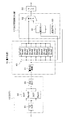
図1、図2に、図9と同様の全体構成となる本例の符号化装置1としてのDCT器15,量子化器16、DCT係数差分化器17の部分の構成を示す。また図3,図4には本例の構成によって行われる処理タイミングを示している。各図を参照しながら本例の構成及び動作を説明していく。
FIGS. 1 and 2 show the configuration of the
図1に示すDCT器15には、図9に示した演算器14から、1マクロブロックにつき、ブロックY0,Y1,Y2,Y3,Cb,Crが順次入力される。DCT器15では水平及び垂直の二次元DCT処理を行う。即ち入力される各ブロックは1stDCT部31で処理された後、バッファ32(DCT Bank0、DCT Bank1)にバッファリングされ、さらに2ndDCT部33で処理される。
例えば図3に示すように、タイミングT1では、入力されたブロックY0が1stDCT処理され、DCT Bank0に書き込まれる。次にタイミングT2では、入力されたブロックY1が1stDCT処理され、DCT Bank1に書き込まれる。このときDCT Bank0からはブロックY0が読み出され、2ndDCT処理される。さらに次にタイミングT3では、入力されたブロックY2が1stDCT処理され、DCT Bank0に書き込まれる。このときDCT Bank1からはブロックY1が読み出され、2ndDCT処理される。バッファ32のDCT Bank0、DCT Bank1は、このように交互に使用される。
The block Y0, Y1, Y2, Y3, Cb, and Cr are sequentially input to the
For example, as shown in FIG. 3, at timing T1, the input block Y0 is subjected to 1st DCT processing and written to DCT Bank0. Next, at timing T2, the input block Y1 is subjected to 1st DCT processing and written to DCT Bank1. At this time, the block Y0 is read from the DCT Bank0 and subjected to 2ndDCT processing. Next, at timing T3, the input block Y2 is subjected to 1st DCT processing and written to DCT Bank0. At this time, the block Y1 is read from the DCT Bank1 and subjected to 2ndDCT processing. The DCT Bank0 and DCT Bank1 of the
DCT器15の出力は量子化器16において、量子化回路41で量子化され、量子化係数バッファ43にバッファリングされる。
この場合、量子化係数バッファ43には、1マクロブロック分のバッファリングを行うことに最低必要な6つのブロックに対応するバンクに加え、さらに1つのバンクを追加的に設けている。即ちDC/AC-Bank0〜DC/AC-Bank6として7個のバンクが設けられている。
量子化された各ブロックのDCT係数は、それぞれ順次DC/AC-Bank0〜DC/AC-Bank6を用いて格納されることになる。7個のバンクが形成されるのは、後述するが量子化係数バッファ43をリングバッファ的に利用できるようにするためである。
The output of the
In this case, the
The quantized DCT coefficients of each block are sequentially stored using DC / AC-
また、量子化回路41で量子化されたDCT係数は、量子化係数バッファ43に取り込まれると同時に、DCT係数差分化器17の差分化回路61にも供給される。
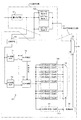
図1において差分化回路61,マルチプレクサ62,逆量子化回路63を有するものとして示すDCT係数差分化器17の構成は、特に差分化回路61の構成を詳細化して図2に示している。
図2に示すように、差分化回路61には、DC係数バッファ71,DC予測部72,AC係数バッファ73,AC予測部74、AC予測値バッファ75,マルチプレクサ76、AC成分加算/比較部77、制御回路78が設けられる。
Further, the DCT coefficient quantized by the
The configuration of the
As shown in FIG. 2, the
DC係数バッファ71には逆量子化回路63で逆量子化されたDC係数が格納される。DC予測部72は、対象となるブロックに隣接する3つのブロック(即ち図7の対象ブロックXに対するブロックA,B,C)の逆量子化されたDC成分を用いて、予測方向及び対象ブロックのDC成分に対する予測誤差を決定する。
なお或るブロックのDC成分予測誤差は、量子化係数バッファ43のDC/AC-Bank0〜DC/AC-Bank6のうちで、そのブロックに対応するバンクの先頭のデータとして格納される。
The
Note that the DC component prediction error of a certain block is stored as the head data of the bank corresponding to the block among DC / AC-
AC係数バッファ73には逆量子化回路63で逆量子化されたAC係数が格納される。
AC予測部74では、DC予測部72で決定される予測方向によって、対象となるブロックに対して参照するブロックが決定される。なお、入力されたDC成分と周辺に隣接するDC成分との勾配によって予測参照するブロックが決定するが、この決定には数サイクル必要とするので、AC予測部74は第一列のAC成分は内部のフリップフロップなどによるテンポラリレジスタに一時保存しておく。
参照するべきブロックが左隣のブロックであれば、第一列成分をAC予測に使用するので、保存した第一列のAC成分とAC係数バッファ73に保存されたAC係数を基に予測誤差を求める。また参照するべきブロックが上のブロックであれば、第一行成分をAC成分に使用するので、保存した第一列のAC成分は使用せず、入力されたAC成分の第一行成分と、それに対応してAC係数バッファ73に保存されたAC係数から予測誤差を求める。
The
In the
If the block to be referred to is a block on the left, the first column component is used for AC prediction. Therefore, the prediction error is calculated based on the stored first column AC component and the AC coefficient stored in the
求められたAC成分予測誤差は、AC予測値バッファ75に格納される。
AC予測値バッファ75には、それぞれが1つのブロックに対応して、AC予測値(AC成分の予測誤差)を保持する領域として、7単位のバンク(AC-Bank0〜AC-Bank6)が設けられている。そして各AC-Bankは、1つのブロックにおける水平第1行又は垂直第1列の7画素分のAC予測値を保持するための領域として、Coef0〜Coef6が用意されている。
AC-Bank0〜AC-Bank6として、1マクロブロックを構成する6つのブロックよりも1つ多い7ブロック分のAC予測値のバンクが形成されるが、算出された各ブロックのAC予測値は、それぞれ順次AC-Bank0〜AC-Bank6を用いて格納されることになる。7個のバンクが形成されるのは、上記量子化係数バッファ43において7個のバンク(DC/AC-Bank0〜DC/AC-Bank6)が形成されることと同じ意味であり、AC予測値バッファ75をリングバッファ的に利用できるようにするためである。
The obtained AC component prediction error is stored in the AC predicted
The AC
As AC-Bank0 to AC-Bank6, a bank of AC predicted values for 7 blocks, one more than the 6 blocks constituting one macroblock, is formed. The calculated AC predicted values of each block are respectively The data is sequentially stored using AC-Bank0 to AC-Bank6. The seven banks are formed in the same meaning as the seven banks (DC / AC-
またAC予測部74で算出された1ブロック分のAC予測値は、AC成分加算/比較部77で加算(絶対値和)され、予測しない絶対値和との比較が行われる。そしてAC成分加算/比較部77は、その比較結果に基づいて、AC予測が有効か否かを示す予測フラグFACを後段の制御回路78に送る。
制御回路78は、予測フラグFACによりAC予測の有効/無効を判別し、それに応じてマルチプレクサ76及び62を制御する。
上記量子化係数バッファ43のバンク(DC/AC-Bank)は、或る1つのブロックについて64個のDCT係数(即ちDC成分1個と63個のAC係数)を格納し、またAC予測値バッファ75のバンク(AC-Bank)は、或るブロックについて7個のAC予測値を格納する。
従って制御回路78は、AC成分予測が有効とされれば、或るブロックの64個のデータ(係数)の出力として、該当するDC/AC-BankからのDC成分1個と56個のAC係数を出力させ、また該当するAC-Bankから7個のAC予測値を出力させる。このような出力が所定の順序で行われるようにマルチプレクサ76及び62を制御する。
またAC成分予測が無効とされれば、AC予測値バッファ75に格納されたAC予測値は出力されず、即ち該当するDC/AC-BankからDC成分1個と63個のAC係数を出力させるように、マルチプレクサ76及び62を制御する。
このようにして出力された係数はVLC器22で可変長符号化されることになる。
Further, the AC prediction value for one block calculated by the
The
The bank (DC / AC-Bank) of the
Therefore, if the AC component prediction is validated, the
If the AC component prediction is invalidated, the AC predicted value stored in the AC predicted
The coefficient output in this way is variable-length encoded by the
以上の図1,図2に示したように本例では、量子化係数バッファ43及びAC予測値バッファ75において7ブロック分のバンクを備えるようにし、さらにDCT係数を量子化係数バッファ43に格納する際に、予測演算のための処理を行ってAC予測値をAC予測値バッファ75に格納するようにすることで、DC/AC予測のパイプライン処理を可能にするものである。
As shown in FIGS. 1 and 2, in this example, the
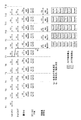
図3により処理タイミングを説明する。
図3のタイミングT1で、或るマクロブロックにおける先頭のブロックY0がDCT器15に入力され、1stDCT処理されるとする。上述したようにDCT器15では、バッファ32のDCT Bank0、DCT Bank1が交互に使用され、バッファリングされながら、1stDCT処理されたデータが次段の2ndDCT処理に供される。例えばタイミングT1からの期間では、1stDCT処理されたブロックY0のデータがDCT Bank0に書き込まれる。次のタイミングT2では、次に入力されたブロックY1が1stDCT処理され、DCT Bank1に書き込まれる。このときDCT Bank0からはブロックY0が読み出され、2ndDCT処理される。
The processing timing will be described with reference to FIG.
Assume that the head block Y0 in a certain macroblock is input to the
ここで、タイミングT2からの期間には、2ndDCT処理されたブロックY0のデータ(64個のDCT係数)が量子化回路41で量子化されるが、量子化処理された各DCT係数が量子化係数バッファ43に書き込まれる。このとき、量子化係数バッファ43においては例えばDC/AC-Bank0に書き込まれるものとなる。なお、図3において「WR」は量子化係数バッファ43及びAC予測値バッファ75への書込、「RD」は量子化係数バッファ43及びAC予測値バッファ75からの読出を示している。
このように量子化器16では、1つのブロックにつき64個のDCT係数を量子化し、量子化係数バッファ43に格納する。このとき、DCTの方法にもよるが、2次元DCTの場合、図5に示すように、DC成分を先頭に第一列から順に縦方向に送られる。
さらにこのタイミングT2からの期間では、ta(Y0)として示す期間において、ブロックY0についてのDC成分及びAC成分の予測演算が行われる。即ち上記図2において説明したように、AC予測値をAC予測値バッファ75の或るバンクに格納するまでの処理が行われる。この場合、量子化係数バッファ43においてDC/AC-Bank0が用いられることに対応して、AC予測値バッファ75ではAC-Bank0が用いられ、AC-Bank0のCoef0〜Coef6に水平又は垂直方向の7個のAC予測値が記憶されるものとなる。
なお、例えばこのta期間においてAC予測値バッファ75の或るバンク(AC-Bank)にAC予測値が記憶される場合の処理タイミングは、後に図4で述べる。
Here, in the period from the timing T2, the data (64 DCT coefficients) of the block Y0 that has been subjected to the 2nd DCT process is quantized by the
Thus, the
Further, in the period from the timing T2, the DC component and AC component prediction calculation for the block Y0 is performed in the period indicated as ta (Y0). That is, as described with reference to FIG. 2, processing until the AC predicted value is stored in a certain bank of the AC predicted
For example, the processing timing when the AC predicted value is stored in a certain bank (AC-Bank) of the AC predicted
次にタイミングT3からの期間では、2ndDCT処理されたブロックY1のデータ(64個のDCT係数)が量子化回路41で量子化され、量子化処理された各DCT係数が量子化係数バッファ43のDC/AC-Bank1に書き込まれるものとなる。
さらにこのタイミングT3からの期間では、ta(Y1)として示す期間において、ブロックY1についてのDC成分及びAC成分の予測演算が行われ、そのAC予測値がAC予測値バッファ75のAC-Bank1に記憶される。即ちAC-Bank1のCoef0〜Coef6に水平又は垂直方向の7個のAC予測値が記憶される。
Next, in the period from the timing T3, the data (64 DCT coefficients) of the block Y1 subjected to the 2nd DCT process is quantized by the
Further, in the period from the timing T3, the DC component and the AC component are predicted for the block Y1 in the period indicated by ta (Y1), and the AC predicted value is stored in the AC-Bank1 of the AC predicted
以降同様に処理されていくと、タイミングT7〜T8の間の期間において、量子化係数バッファ43のDC/AC-Bank0〜DC/AC-Bank5に、各ブロックY0,Y1,Y2,Y3,Cb,Crについての量子化DCT係数が書き込まれた状態となり、さらにAC予測値バッファ75のAC-Bank0〜AC-Bank5には、各ブロックについてのAC予測値が記憶された状態となる。
そこでタイミングT7〜T8の間の期間tbでは、図2のAC成分加算/比較部77で、1マクロブロック内の全てのブロックのAC予測値の絶対値和と、予測しない絶対値和との比較ができることになり、その結果としてAC予測が有効か否かを示す予測フラグFACを後段の制御回路78に送ることができる。
従って、タイミングT8からは、制御回路78は、予測フラグFACによりAC予測の有効/無効を判別し、それに応じてマルチプレクサ62,76を制御して、AC予測値を有効化するか否かに応じた状態で、後段のVLC器22(可変長符号化処理)に対するDCT係数の出力を行うことができる。
図示するように、タイミングT8では、ブロックY0の係数出力として、量子化係数バッファ43のDC/AC-Bank0に格納されたDCT係数と、AC予測値バッファ75のAC-Bank0に格納されたAC予測値の読出が行われ、後段のVLC器22で可変長符号化処理が行われる。もちろん、1ブロックにつき出力される64個の係数データのうちにAC-Bank0に格納された7個のAC予測値が含まれることになるのは、AC予測が有効化された場合であり、AC予測が無効とされた場合は、DC/AC-Bank0に格納された64個のDCT係数が出力される。
Thereafter, if the same processing is performed, each of the blocks Y0, Y1, Y2, Y3, Cb, and DC / AC-Bank0 to DC / AC-Bank5 of the
Therefore, in the period tb between timings T7 and T8, the AC component addition /
Therefore, from the timing T8, the
As shown in the figure, at timing T8, the DCT coefficient stored in DC / AC-Bank0 of the
またタイミングT9からは、ブロックY1の係数出力として、量子化係数バッファ43のDC/AC-Bank1に格納されたDCT係数の読出と、AC予測値バッファ75のAC-Bank1に格納されたAC予測値の読出が行われ(但しAC予測が有効とされた場合のみ)、後段のVLC器22で可変長符号化処理が行われる。
さらにタイミングT10からは、ブロックY2の係数出力として、量子化係数バッファ43のDC/AC-Bank2に格納されたDCT係数の読出と、AC予測値バッファ75のAC-Bank2に格納されたAC予測値の読出が行われ(但しAC予測が有効とされた場合のみ)、後段のVLC器22で可変長符号化処理が行われる。
以降も同様である。
From timing T9, as the coefficient output of the block Y1, the DCT coefficient stored in the DC / AC-Bank1 of the
Further, from timing T10, as the coefficient output of the block Y2, the DCT coefficient stored in the DC / AC-Bank2 of the
The same applies thereafter.
ここで、この図3においてはタイミングT7からの期間には、次のマクロブロックの先頭のブロックY0についての1stDCT処理が行われるものとなっている。
そしてタイミングT7で1stDCT処理されたブロックY0のデータは、タイミングT8からの期間において、2ndDCT及び量子化されることになり、このとき量子化されたDCT係数が量子化係数バッファ43に書き込まれる。
このとき、量子化係数バッファ43に7単位のバンクが設けられていることから、この場合、図示するようにブロックY0の64個の量子化DCT係数は、量子化係数バッファ43のDC/AC-Bank6に書き込まれるものとされる。
上記のようにタイミングT8からの期間は、直前のマクロブロックのブロックY0のDCT係数がDC/AC-Bank0から読み出されている期間であるが、異なるバンクであるDC/AC-Bank6に対して書込が行われるため、量子化係数バッファ43においてオーバーライトは発生しない。
可変長符号化のDCT量子化係数の読み出しはジグザグスキャン、垂直スキャン、水平スキャンなどスキャン方法が変わると読み出し順序が変わるが、そのような事情を考慮しても、読み出しを行っているバンクに対して書込を行うものではないため、オーバライト発生の可能性は解消されるものである。
Here, in FIG. 3, during the period from the timing T7, the 1st DCT process is performed for the first block Y0 of the next macroblock.
The data of the block Y0 subjected to the 1st DCT process at the timing T7 is quantized and 2nd DCT in the period from the timing T8. At this time, the quantized DCT coefficients are written in the
At this time, since the bank of 7 units is provided in the
As described above, the period from the timing T8 is a period in which the DCT coefficient of the block Y0 of the immediately preceding macroblock is read from the DC / AC-Bank0, but for the DC / AC-Bank6 which is a different bank. Since writing is performed, no overwriting occurs in the
The DCT quantization coefficient for variable length coding is read out when the scanning method changes, such as zigzag scanning, vertical scanning, and horizontal scanning. Thus, the possibility of overwriting is eliminated.
また、このタイミングT8のta(Y0)で示す期間には、ブロックY0についてのDC成分及びAC成分の予測演算が行われ、そのAC予測値がAC予測値バッファ75のAC-Bank6に記憶される。即ちAC-Bank6のCoef0〜Coef6に水平又は垂直方向の7個のAC予測値が記憶される。
この場合も、AC予測値バッファ75では、直前のマクロブロックのブロックY0のAC予測値がAC-Bank0から読み出されている期間であるが、異なるバンクであるAC-Bank6に対して書込が行われるため、AC予測値バッファ75においてもオーバーライトは発生しない。
In addition, during the period indicated by ta (Y0) at timing T8, the DC component and AC component prediction calculation for block Y0 is performed, and the AC prediction value is stored in AC-
Also in this case, the AC predicted
同様にタイミングT9からの期間は、直前のマクロブロックのブロックY1についてのDCT係数がDC/AC-Bank1から読み出され、AC予測値がAC-Bank1から読み出される期間とされるが、このとき今回のマクロブロックのブロックY1のDCT係数は、DC/AC-Bank0に書き込まれ、AC予測値がAC-Bank0に書き込まれることになる。
またタイミングT10からの期間は、直前のマクロブロックのブロックY2についてのDCT係数がDC/AC-Bank2から読み出され、AC予測値がAC-Bank2から読み出される期間とされるが、このとき今回のマクロブロックのブロックY2のDCT係数は、DC/AC-Bank1に書き込まれ、AC予測値がAC-Bank1に書き込まれることになる。
つまり量子化係数バッファ43及びAC予測値バッファ75においてオーバーライトは発生しない。従って、図示するように、タイミングT7から次のマクロブロックのDCT処理を開始することに問題ないものとなる。これによって図11のT7〜T8又はT7〜T9として示したような処理待機期間の無い、パイプライン処理が実現できる。
Similarly, the period from timing T9 is a period in which the DCT coefficient for the block Y1 of the immediately preceding macroblock is read from DC / AC-Bank1 and the AC predicted value is read from AC-Bank1, but this time The DCT coefficient of the block Y1 of the macroblock is written to DC / AC-Bank0, and the AC prediction value is written to AC-Bank0.
The period from the timing T10 is a period in which the DCT coefficient for the block Y2 of the immediately preceding macroblock is read from the DC / AC-Bank2 and the AC predicted value is read from the AC-Bank2. The DCT coefficient of block Y2 of the macro block is written to DC / AC-Bank1, and the AC prediction value is written to AC-Bank1.
That is, no overwrite occurs in the
ところでこのようなパイプライン処理が実現できることは、量子化係数バッファ43及びAC予測値バッファ75において7個のバンクを設けることに加え、図3に期間ta(Y0)〜ta(Cr)として示したように、DC/AC予測演算及びAC予測値バッファ75へのAC予測値の書込を、2ndDCT処理→量子化→量子化DCT係数の量子化係数バッファ43への書き込みという処理を実行する期間と同時的に実行することが必要となるものである。
即ち図11の従来例においては、期間t1、t2でDC/AC係数の読出と予測演算が行われ、その後AC予測の有効/無効判断が行われていたことも、パイプライン処理を妨げる要因となっていた。これに対して本例では、各ブロックについてのDC/AC予測演算及びAC予測値バッファ75へのAC予測値の書込を、期間ta(Y0)〜ta(Cr)において行い、タイミングT7からの期間において1マクロブロックを構成する各ブロックの量子化DCT係数及びAC予測値が蓄積された直後に、図3に示す期間tbとして、単にAC予測の有効/無効判断を行うことで、タイミングT8から次段の可変長符号化処理への出力が可能となり、これもパイプライン処理を実現する要素となる。
By the way, such pipeline processing can be realized in addition to providing seven banks in the quantized
In other words, in the conventional example shown in FIG. 11, the DC / AC coefficient reading and prediction calculation are performed in the periods t1 and t2, and the AC prediction validity / invalidity determination is subsequently performed. It was. On the other hand, in this example, the DC / AC prediction calculation for each block and the writing of the AC predicted value to the AC predicted
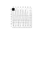
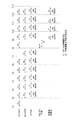
期間ta(ta(Y0)〜ta(Cr))において実行される処理を図4で説明する。
図4は例えば図3のタイミングT3〜T4の期間を例に挙げて、1ブロック分の処理のタイミングを示したものである。
例えばブロックY1としての64個のDCT係数として、2ndDCT処理されて量子化される8×8の係数を(0,0)〜(7,7)として示す。1ブロック期間は64サイクルの処理となる。
図2のDC予測部72では、係数(0,0)が入力された後のタイミングでDC予測を行い、予測方向を決定できる。なお、この処理には数サイクルの期間を必要とする。
一方、AC予測部74では、AC予測値バッファ75に格納するAC予測値は、DC予測によって予測方向が決まるまでは確定させることができないが、順次入力される係数(0,1)〜(0,7)は、もし水平方向予測とされた場合に用いる係数となるため、これらを内部のテンポラリレジスタに格納しておく。
DC予測の結果に基づいて図に示すタイミングで予測方向が決定されると、それが水平方向予測であった場合は、AC予測部74は、テンポラリレジスタに格納しておいた係数(0,1)〜(0,7)によりAC予測値を得、これをAC予測値バッファ75の所定のAC-BankのCoef0〜Coef6に格納させる。
また垂直方向予測と決定された場合は、AC予測部74は、図示するように、以降入力されてくる係数(1,0)、(2,0)・・・(6,0)、(7,0)を用いてAC予測値を得、これをAC予測値バッファ75の所定のAC-BankのCoef0〜Coef6に格納させる。
Processing executed in the period ta (ta (Y0) to ta (Cr)) will be described with reference to FIG.
FIG. 4 shows the processing timing for one block, taking the period from timing T3 to T4 in FIG. 3 as an example.
For example, as 64 DCT coefficients as the block Y1, 8 × 8 coefficients quantized by 2ndDCT processing are shown as (0, 0) to (7, 7). One block period is a process of 64 cycles.
The
On the other hand, the
When the prediction direction is determined at the timing shown in the figure based on the result of DC prediction, if it is horizontal prediction, the
If it is determined that the prediction is in the vertical direction, the
即ち図2の構成を採ることで、図4のように、或るブロックの量子化DCT係数を量子化係数バッファ43に格納する期間に、同時的にAC予測値を算出し、AC予測値バッファ75に格納していくことができる。
これによって上記図3のように、マクロブロック内の6個目のブロックCrについて、そのDCT係数を量子化係数バッファ43に格納した直後の時点では、単にAC予測の有効/無効を判断して、後段のVLC器22に対する出力処理に移ることができ、上記オーバライトの解消と合わせて、パイプライン処理を実現するものとなる。
That is, by adopting the configuration of FIG. 2, as shown in FIG. 4, an AC predicted value is calculated simultaneously during a period in which the quantized DCT coefficient of a certain block is stored in the quantized
Accordingly, as shown in FIG. 3 above, at the time immediately after the DCT coefficient is stored in the
また、このように各ブロックについて、2ndDCT処理→量子化→量子化DCT係数の量子化係数バッファ43への書き込みという処理を実行する期間と同時的に期間taでAC予測値の演算及びAC予測値バッファ75への格納を行うことは、量子化係数バッファ43及びAC予測値バッファ75に1つのバンクを追加するのみで、パイプライン処理を行った場合のオーバライトが発生しないようにするものともなる。これを図6で説明する。
図6は、仮に、量子化係数バッファ43及びAC予測値バッファ75に7単位のバンクを設けるがAC予測演算を上記ta期間では行わないようにした場合の処理タイミングを示している。
上記図3のta期間で示したタイミングでのAC予測演算を行わないものとした場合は、図6のように、タイミングT8からのt1期間でDC/AC係数の読み出しを行い、続くt2期間に予測演算及び予測方向を決定し、またAC予測の有効/無効を判断することになる。
すると、後段のVLC器22への出力は、図示するようにT8〜T9の間の後半のタイミングから可能となり、タイミングT9以降にまでわたって出力(量子化係数バッファ43のDC/AC-Bank0及びAC予測値バッファ75のAC-Bank0からの読出)が実行される。
この場合、図からわかるように、タイミングT9以降では、量子化係数バッファ43のDC/AC-Bank0及びAC予測値バッファ75のAC-Bank0に対しては、次のマクロブロックに関しての書込が行われている。従って、後段のVLC処理のサイクルによっては、ここにオーバライトの可能性が生ずる。
即ち、量子化係数バッファ43及びAC予測値バッファ75においてバンクを1つ追加したのみでは、パイプライン処理を安全に実行できない場合があるが、上記図3で説明したように本例では、各ブロックについて、量子化DCT係数を量子化係数バッファ43に格納する期間に、同時的にAC予測値を算出し、AC予測値バッファ75に格納することで、確実に安全なパイプライン処理が実現できるものである。
As described above, for each block, the calculation of the AC predicted value and the AC predicted value are performed in the period ta simultaneously with the period in which the process of 2ndDCT processing → quantization → writing of the quantized DCT coefficient to the
FIG. 6 shows the processing timing when a bank of 7 units is provided in the
When the AC prediction calculation is not performed at the timing shown in the ta period in FIG. 3, the DC / AC coefficient is read out in the t1 period from the timing T8 as shown in FIG. The prediction calculation and the prediction direction are determined, and the validity / invalidity of the AC prediction is determined.
Then, the output to the
In this case, as can be seen from the figure, after timing T9, the writing of the next macroblock is performed on DC / AC-Bank0 of the
That is, the pipeline processing may not be executed safely only by adding one bank in the
以上のように本例では、AC予測演算をブロック処理サイクル内で実現できることで、1マクロブロックで64サイクルのサイクル数削減が実現できる。また従来のようにオーバライトを考慮して処理を待機する期間も不要となり、この点でも1マクロブロックで64サイクルのサイクル数削減が実現できる。
例えばMPEGのコーデックブロックは1サイクルでも早くエンコード/デコードすることが望まれるが、本例の構成を使用するとQCIFサイズの99マクロブロックでは、少なくとも1フレームあたり99×64=6336のサイクル数削減が期待できるものとなる。
As described above, in this example, since the AC prediction calculation can be realized within the block processing cycle, the number of cycles can be reduced by 64 cycles with one macroblock. In addition, a period of waiting for processing in consideration of overwriting as in the prior art is not required, and in this respect as well, a cycle number reduction of 64 cycles can be realized with one macroblock.
For example, it is desirable to encode / decode MPEG codec blocks as early as possible even with one cycle, but with the configuration of this example, 99 macroblocks of QCIF size are expected to reduce the number of cycles by at least 99 x 64 = 6336 per frame. It will be possible.
なお、上記例では量子化係数バッファ43及びAC予測値バッファ75にはバンクを最低限必要な6単位より1つ追加して7単位としたが、さらに追加して8単位以上とする例も考えられる。
In the above example, the quantized
15 DCT器、16 量子化器、17 DCT係数差分化器、22 VLC器、41 量子化回路、43 量子化係数バッファ、61 差分化回路、62 マルチプレクサ、63 逆量子化回路、71 DC係数バッファ71、72 DC予測部、73 AC係数バッファ、74 AC予測部、75 AC予測値バッファ、76 マルチプレクサ、77 AC成分加算/比較部、78 制御回路 15 DCT units, 16 quantizers, 17 DCT coefficient differentiators, 22 VLC units, 41 quantization circuits, 43 quantization coefficient buffers, 61 difference circuits, 62 multiplexers, 63 inverse quantization circuits, 71 DC coefficient buffers 71 72 DC prediction unit, 73 AC coefficient buffer, 74 AC prediction unit, 75 AC prediction value buffer, 76 multiplexer, 77 AC component addition / comparison unit, 78 control circuit
Claims (2)
(n+1)個以上の記憶領域が設けられ、各記憶領域へ各ブロックの量子化離散コサイン変換係数が順次格納される第1の記憶手段と、
(n+1)個以上の記憶領域が設けられ、各記憶領域へ各ブロックのAC成分予測誤差が順次格納される第2の記憶手段と、
或るブロックの量子化離散コサイン変換係数を上記第1の記憶手段に記憶させる期間において、該ブロックについてのAC成分予測誤差演算を行い、上記第2の記憶手段に算出された該AC成分予測誤差を記憶させるAC予測演算手段と、
上記マクロブロックに含まれる全ブロックのAC成分予測誤差を用いて該AC成分予測の有効/無効を判別し、上記可変長符号化処理に供する上記量子化離散コサイン変換係数及び上記AC成分予測誤差を、該判別結果に基づいて上記第1,第2の記憶手段から読み出す読出制御手段と、
を備えたことを特徴とする符号化装置。 In an encoding device that performs discrete cosine transform, quantization of discrete cosine transform coefficients, and variable length coding on image data in which a macroblock is formed by n blocks composed of luminance components and color difference components.
(N + 1) or more storage areas are provided, and first storage means for sequentially storing the quantized discrete cosine transform coefficients of each block in each storage area;
(N + 1) or more storage areas are provided, and second storage means for sequentially storing the AC component prediction error of each block in each storage area;
In a period in which the quantized discrete cosine transform coefficient of a certain block is stored in the first storage unit, the AC component prediction error calculation is performed on the block and the AC component prediction error calculated in the second storage unit is performed. AC prediction calculation means for storing
Validity / invalidity of the AC component prediction is determined using AC component prediction errors of all blocks included in the macroblock, and the quantized discrete cosine transform coefficient and the AC component prediction error used for the variable-length coding process are determined. Read control means for reading from the first and second storage means based on the determination result;
An encoding device comprising:
離散コサイン変換により得られた離散コサイン変換係数を量子化する量子化ステップと、
上記量子化された量子化離散コサイン変換係数を、(n+1)個以上の記憶領域が設けられた第1の記憶手段の上記記憶領域毎に順次記憶する第1の記憶ステップと、
上記第1の記憶ステップと並行して、順次各ブロックについてのAC成分予測誤差演算を行い、得られたAC成分予測誤差を、(n+1)個以上の記憶領域が設けられた第2の記憶手段の上記記憶領域毎に順次記憶する第2の記憶ステップと、
上記マクロブロックに含まれる全ブロックのAC成分予測誤差を用いて該AC成分予測の有効/無効を判別し、上記可変長符号化処理に供する上記量子化離散コサイン変換係数及び上記AC成分予測誤差を、該判別結果に基づいて上記第1,第2の記憶手段から読み出す読み出しステップと、
上記読み出しステップで読み出された上記量子化離散コサイン変換係数及び上記AC成分予測誤差を用いて可変長符号化処理を行う可変長符号化ステップと、
を有することを特徴とする符号化方法。 A discrete cosine transform step for sequentially performing discrete cosine transform in units of blocks on image data in which a macroblock is formed by n blocks composed of a luminance component and a color difference component;
A quantization step for quantizing the discrete cosine transform coefficient obtained by the discrete cosine transform;
A first storage step of sequentially storing the quantized quantized discrete cosine transform coefficients for each of the storage areas of the first storage means provided with (n + 1) or more storage areas;
In parallel with the first storage step, AC component prediction error calculation is sequentially performed for each block, and the obtained AC component prediction error is converted into second storage means provided with (n + 1) or more storage areas. A second storage step for sequentially storing each of the storage areas;
Validity / invalidity of the AC component prediction is determined using AC component prediction errors of all blocks included in the macroblock, and the quantized discrete cosine transform coefficient and the AC component prediction error used for the variable-length coding process are determined. A reading step of reading from the first and second storage means based on the determination result;
A variable length encoding step for performing a variable length encoding process using the quantized discrete cosine transform coefficient and the AC component prediction error read in the reading step;
An encoding method characterized by comprising:
Priority Applications (1)
| Application Number | Priority Date | Filing Date | Title |
|---|---|---|---|
| JP2003354886A JP2005123783A (en) | 2003-10-15 | 2003-10-15 | Encoding apparatus and encoding method |
Applications Claiming Priority (1)
| Application Number | Priority Date | Filing Date | Title |
|---|---|---|---|
| JP2003354886A JP2005123783A (en) | 2003-10-15 | 2003-10-15 | Encoding apparatus and encoding method |
Publications (1)
| Publication Number | Publication Date |
|---|---|
| JP2005123783A true JP2005123783A (en) | 2005-05-12 |
Family
ID=34612669
Family Applications (1)
| Application Number | Title | Priority Date | Filing Date |
|---|---|---|---|
| JP2003354886A Pending JP2005123783A (en) | 2003-10-15 | 2003-10-15 | Encoding apparatus and encoding method |
Country Status (1)
| Country | Link |
|---|---|
| JP (1) | JP2005123783A (en) |
Cited By (1)
| Publication number | Priority date | Publication date | Assignee | Title |
|---|---|---|---|---|
| JP2008141276A (en) * | 2006-11-30 | 2008-06-19 | Sanyo Electric Co Ltd | TV signal processing circuit |
-
2003
- 2003-10-15 JP JP2003354886A patent/JP2005123783A/en active Pending
Cited By (2)
| Publication number | Priority date | Publication date | Assignee | Title |
|---|---|---|---|---|
| JP2008141276A (en) * | 2006-11-30 | 2008-06-19 | Sanyo Electric Co Ltd | TV signal processing circuit |
| US8311123B2 (en) | 2006-11-30 | 2012-11-13 | Semiconductor Components Industries, Llc | TV signal processing circuit |
Similar Documents
| Publication | Publication Date | Title |
|---|---|---|
| EP1853069B1 (en) | Decoding macroblock type and coded block pattern information | |
| CN101562749B (en) | Video data compression with integrated lossy and lossless compression | |
| JP2022518587A (en) | Transformation of decoded block vector for intra image block compensation | |
| US20020057739A1 (en) | Method and apparatus for encoding video | |
| WO2006008609A1 (en) | System and method for motion prediction in scalable video coding | |
| CN101208954A (en) | Video decoder with variable compression ratio and buffer for storing and retrieving reference frame data | |
| JP2009267689A (en) | Moving image coding device, and moving image coding method | |
| JP3918263B2 (en) | Compression encoding apparatus and encoding method | |
| JP4502203B2 (en) | Image encoding apparatus and image decoding apparatus | |
| CN1937773A (en) | External memory device, method of storing image data for the same, and image processor using the method | |
| JP2002199392A (en) | Video encoding method and apparatus | |
| CN100428800C (en) | Moving image decoding device and method | |
| EP1083752A1 (en) | Video decoder with reduced memory | |
| JP4165752B2 (en) | Secret data insertion method and secret data detection method for image data | |
| JP5080304B2 (en) | Display method of image data with confidential data inserted | |
| CN1968420B (en) | Image Processing Method Applied to Image Decoder and Encoder | |
| WO2006126694A2 (en) | Video coding using an alternative reference frame for motion compensated prediction | |
| JP2004521547A (en) | Video encoder and recording device | |
| JP2005123783A (en) | Encoding apparatus and encoding method | |
| JPH08242446A (en) | Image processing method and image processing apparatus | |
| KR100522595B1 (en) | MPEG video decoding methods and MPEG video decoders | |
| JP3854717B2 (en) | Decoding apparatus and method | |
| JP4361665B2 (en) | Transcoding method and transcoding apparatus for moving image encoded data | |
| US20090198757A1 (en) | Method and device for avoiding rounding errors after performing an inverse discrete cosine transformation | |
| JP2001045493A (en) | Video encoding device, video output device, and storage medium |