JP2005106902A - Projection lens and color synthesis optical system using the same - Google Patents
Projection lens and color synthesis optical system using the same Download PDFInfo
- Publication number
- JP2005106902A JP2005106902A JP2003336905A JP2003336905A JP2005106902A JP 2005106902 A JP2005106902 A JP 2005106902A JP 2003336905 A JP2003336905 A JP 2003336905A JP 2003336905 A JP2003336905 A JP 2003336905A JP 2005106902 A JP2005106902 A JP 2005106902A
- Authority
- JP
- Japan
- Prior art keywords
- lens
- projection
- optical system
- conjugate side
- color
- Prior art date
- Legal status (The legal status is an assumption and is not a legal conclusion. Google has not performed a legal analysis and makes no representation as to the accuracy of the status listed.)
- Withdrawn
Links
Images


Classifications
-
- G—PHYSICS
- G02—OPTICS
- G02B—OPTICAL ELEMENTS, SYSTEMS OR APPARATUS
- G02B15/00—Optical objectives with means for varying the magnification
- G02B15/14—Optical objectives with means for varying the magnification by axial movement of one or more lenses or groups of lenses relative to the image plane for continuously varying the equivalent focal length of the objective
- G02B15/16—Optical objectives with means for varying the magnification by axial movement of one or more lenses or groups of lenses relative to the image plane for continuously varying the equivalent focal length of the objective with interdependent non-linearly related movements between one lens or lens group, and another lens or lens group
- G02B15/177—Optical objectives with means for varying the magnification by axial movement of one or more lenses or groups of lenses relative to the image plane for continuously varying the equivalent focal length of the objective with interdependent non-linearly related movements between one lens or lens group, and another lens or lens group having a negative front lens or group of lenses
-
- G—PHYSICS
- G02—OPTICS
- G02B—OPTICAL ELEMENTS, SYSTEMS OR APPARATUS
- G02B13/00—Optical objectives specially designed for the purposes specified below
- G02B13/22—Telecentric objectives or lens systems
-
- G—PHYSICS
- G02—OPTICS
- G02B—OPTICAL ELEMENTS, SYSTEMS OR APPARATUS
- G02B15/00—Optical objectives with means for varying the magnification
- G02B15/14—Optical objectives with means for varying the magnification by axial movement of one or more lenses or groups of lenses relative to the image plane for continuously varying the equivalent focal length of the objective
- G02B15/144—Optical objectives with means for varying the magnification by axial movement of one or more lenses or groups of lenses relative to the image plane for continuously varying the equivalent focal length of the objective having four groups only
- G02B15/1445—Optical objectives with means for varying the magnification by axial movement of one or more lenses or groups of lenses relative to the image plane for continuously varying the equivalent focal length of the objective having four groups only the first group being negative
- G02B15/144515—Optical objectives with means for varying the magnification by axial movement of one or more lenses or groups of lenses relative to the image plane for continuously varying the equivalent focal length of the objective having four groups only the first group being negative arranged -+++
-
- G—PHYSICS
- G02—OPTICS
- G02B—OPTICAL ELEMENTS, SYSTEMS OR APPARATUS
- G02B15/00—Optical objectives with means for varying the magnification
- G02B15/14—Optical objectives with means for varying the magnification by axial movement of one or more lenses or groups of lenses relative to the image plane for continuously varying the equivalent focal length of the objective
- G02B15/145—Optical objectives with means for varying the magnification by axial movement of one or more lenses or groups of lenses relative to the image plane for continuously varying the equivalent focal length of the objective having five groups only
- G02B15/1455—Optical objectives with means for varying the magnification by axial movement of one or more lenses or groups of lenses relative to the image plane for continuously varying the equivalent focal length of the objective having five groups only the first group being negative
- G02B15/145527—Optical objectives with means for varying the magnification by axial movement of one or more lenses or groups of lenses relative to the image plane for continuously varying the equivalent focal length of the objective having five groups only the first group being negative arranged -+-++
-
- G—PHYSICS
- G02—OPTICS
- G02B—OPTICAL ELEMENTS, SYSTEMS OR APPARATUS
- G02B15/00—Optical objectives with means for varying the magnification
- G02B15/14—Optical objectives with means for varying the magnification by axial movement of one or more lenses or groups of lenses relative to the image plane for continuously varying the equivalent focal length of the objective
- G02B15/145—Optical objectives with means for varying the magnification by axial movement of one or more lenses or groups of lenses relative to the image plane for continuously varying the equivalent focal length of the objective having five groups only
- G02B15/1455—Optical objectives with means for varying the magnification by axial movement of one or more lenses or groups of lenses relative to the image plane for continuously varying the equivalent focal length of the objective having five groups only the first group being negative
- G02B15/145531—Optical objectives with means for varying the magnification by axial movement of one or more lenses or groups of lenses relative to the image plane for continuously varying the equivalent focal length of the objective having five groups only the first group being negative arranged -++++
-
- G—PHYSICS
- G02—OPTICS
- G02B—OPTICAL ELEMENTS, SYSTEMS OR APPARATUS
- G02B15/00—Optical objectives with means for varying the magnification
- G02B15/14—Optical objectives with means for varying the magnification by axial movement of one or more lenses or groups of lenses relative to the image plane for continuously varying the equivalent focal length of the objective
- G02B15/146—Optical objectives with means for varying the magnification by axial movement of one or more lenses or groups of lenses relative to the image plane for continuously varying the equivalent focal length of the objective having more than five groups
- G02B15/1465—Optical objectives with means for varying the magnification by axial movement of one or more lenses or groups of lenses relative to the image plane for continuously varying the equivalent focal length of the objective having more than five groups the first group being negative
Landscapes
- Physics & Mathematics (AREA)
- General Physics & Mathematics (AREA)
- Optics & Photonics (AREA)
- Nonlinear Science (AREA)
- Liquid Crystal (AREA)
- Projection Apparatus (AREA)
- Lenses (AREA)
Abstract
【課題】 色合成プリズムと液晶パネルとの間に正レンズを有する構成の液晶プロジェクタに好適な色合成投射光学系を提供すること。
【解決手段】 3つの液晶パネルと、この3つの液晶パネルからの出射光を合成する色合成系と、この色合成系から出射した光を投射する投射レンズとを有し、この色合成系と液晶パネルとの間に正レンズを有しており、さらに、投射レンズ中の正レンズ群内に回折光学素子を少なくとも1つ有する。
【選択図】 図1
PROBLEM TO BE SOLVED: To provide a color composition projection optical system suitable for a liquid crystal projector having a positive lens between a color composition prism and a liquid crystal panel.
SOLUTION: There are three liquid crystal panels, a color composition system that synthesizes light emitted from the three liquid crystal panels, and a projection lens that projects light emitted from the color composition system. A positive lens is provided between the liquid crystal panel and at least one diffractive optical element in the positive lens group in the projection lens.
[Selection] Figure 1
Description
本発明は、ライトバルブに表示された像をスクリーン上に拡大投影するプロジェクタ装置の投射用ズームレンズ及び色合成光学系に関し、特に液晶プロジェクタ装置に好適な色合成投射光学系に関するものである。 The present invention relates to a projection zoom lens and a color composition optical system of a projector device that enlarges and projects an image displayed on a light valve onto a screen, and more particularly to a color composition projection optical system suitable for a liquid crystal projector device.
液晶パネル等の表示画像をスクリーン等の表示媒体上に拡大投影する液晶プロジェクタ等の投射型の表示装置は、近年大幅にその性能が向上し、ビデオ再生画像やコンピュータのデータ等の表示用として、広く普及してきている。 Projection-type display devices such as liquid crystal projectors that enlarge and project a display image such as a liquid crystal panel onto a display medium such as a screen have been greatly improved in recent years, and for displaying video playback images, computer data, etc. It has become widespread.
中でも、赤・緑・青の各色画像を独立した液晶パネルに表示し、各色画像を合成して拡大投射する「3板式液晶プロジェクタ」がよく知られている。この「3板式液晶プロジェクタ」は、3つの液晶パネルに表示された画像をスクリーン上に重ねてカラー画像として表示するために、光路上にダイクロイックプリズム等の色合成光学系を用いている。この色合成光学系において、広く一般に使用されているのが、ダイクロイック層をプリズム内部で交差させているクロスダイクロプリズムを用いたタイプである。このクロスダイクロプリズムは小型であるが、製造する際、4つの直角プリズムの角度を正確に研磨しないとスクリーン上の投影像が二重像となり、解像感が著しく悪くなったり、また、接合時に接合面に段差が生じていたりしていると、スクリーン上へ投射した際、クロスプリズムのクロスする部分が縦筋となって表れてしまうといった問題点があった。このように、従来のクロスダイクロプリズムは、プリズムの加工及び接合が非常に難しく、製造コストを安くするのが困難だった。 Among them, a “three-plate type liquid crystal projector” that displays red, green, and blue color images on independent liquid crystal panels and synthesizes and magnifies the color images is well known. This “three-plate liquid crystal projector” uses a color synthesizing optical system such as a dichroic prism on the optical path in order to display images displayed on three liquid crystal panels on a screen as a color image. In this color synthesis optical system, a type that uses a cross dichroic prism in which dichroic layers intersect each other inside the prism is widely used. Although this cross dichroic prism is small, if the angles of the four right angle prisms are not polished accurately during manufacture, the projected image on the screen will be a double image, and the resolution will be significantly worse, If there is a difference in level on the joint surface, there is a problem in that the crossed portion of the cross prism appears as vertical stripes when projected onto the screen. As described above, in the conventional cross dichroic prism, it is very difficult to process and join the prisms, and it is difficult to reduce the manufacturing cost.
このような問題を解決するために、図301に示すような(例えば特許文献1等)構成で上記の問題を解決しようとしていた。
しかしながら、前記提案の色合成光学系に対する投射光学系は、まだまだレンズ全系が小型化されているとは言い難く、また色収差をはじめとした諸収差の補正が十分なされていなく、前記提案の色合成光学系に最適な投射光学系とは言い難かった。 However, the projection optical system for the proposed color synthesizing optical system is still difficult to say that the entire lens system has been downsized, and various aberrations including chromatic aberration have not been sufficiently corrected. It was difficult to say that it was the optimal projection optical system for the synthesis optical system.
本発明は、上記課題を解決し、色収差をはじめとした諸収差を十分に補正するとともに、投射光学系のレンズ全長の短縮を図った、前記提案の色合成光学系に最適な、液晶プロジェクタ等に使用される、液晶画像等を拡大投影するための表示装置に好適な投射光学系及び色合成光学系から成る色合成投射光学系の提供を目的とする。 The present invention solves the above-described problems, sufficiently corrects various aberrations including chromatic aberration, and shortens the total lens length of the projection optical system, and is suitable for the proposed color synthesizing optical system. An object of the present invention is to provide a color synthesis projection optical system including a projection optical system and a color synthesis optical system suitable for a display device for enlarging and projecting a liquid crystal image or the like.
上記課題を達成するために、本発明の色合成投射光学系は、以下のように構成することを特徴としている。 In order to achieve the above object, the color synthesis projection optical system according to the present invention is configured as follows.
(1)本発明の色合成投射光学系は、投射レンズと前記投射レンズよりも縮小共役側に色合成プリズムと画像変調装置を備え、前記色合成プリズムと前記画像変調装置との間に、全体として正の屈折力のレンズ群を配置した構成であり、前記投射レンズ、前記色合成プリズム、及び前記色合成プリズムと前記画像変調装置との間に配置された全体として正の屈折力のレンズ群のいずれかの部分に、回折光学素子を少なくとも1つ有していることを特徴としている。 (1) The color synthesis projection optical system of the present invention includes a projection lens and a color synthesis prism and an image modulation device closer to the reduction conjugate side than the projection lens, and the whole is disposed between the color synthesis prism and the image modulation device. And a lens group having a positive refractive power as a whole arranged between the projection lens, the color synthesis prism, and the color synthesis prism and the image modulation device. It is characterized by having at least one diffractive optical element in any part of the above.
(2)本発明の色合成投射光学系は、特に前記投射レンズ内に、前記回折光学素子を少なくとも1つ有していることを特徴としている。 (2) The color synthesis projection optical system of the present invention is characterized in that at least one diffractive optical element is provided in the projection lens.
(3)本発明の色合成投射光学系は、前記色合成光学系において、前記色合成プリズムと前記画像変調装置との間に配置されている全体として正の屈折力のレンズ群と前記投射レンズとの間に、以下の条件式が成り立っていることを特徴としている。 (3) The color synthesis projection optical system according to the present invention includes a lens group having a positive refractive power as a whole and the projection lens disposed between the color synthesis prism and the image modulation device in the color synthesis optical system. Is characterized by the following conditional expression.
0.30 < b.f./ f P-I < 0.70 ……………(1)
ここで、b.f.は拡大共役側の共役点が無限大時の縮小共役側のバックフォーカス(ここにおけるb.f.の値は、前記投射レンズと縮小共役点の間に配置されたプリズム等のガラスブロックを空気に換算した際の値)であり、f P-Iは前記色合成プリズムと前記画像変調装置との間に配置されている全体として正の屈折力のレンズ群の焦点距離を表している。
0.30 <b. f. / f PI <0.70 …………… (1)
Where b. f. Is the back focus on the reduction conjugate side when the conjugate point on the enlargement conjugate side is infinite (the value of bf here is the air flow through a glass block such as a prism disposed between the projection lens and the reduction conjugate point) F PI represents the focal length of the lens unit having a positive refractive power as a whole disposed between the color synthesizing prism and the image modulation device.
(4)本発明の色合成投射光学系は、最も拡大共役側に配置されたレンズ群が負の屈折力で始まる単焦点レンズであることを特徴としている。 (4) The color composition projection optical system of the present invention is characterized in that the lens group arranged closest to the magnification conjugate side is a single focus lens starting with a negative refractive power.
(5)本発明の色合成投射光学系は、最も拡大共役側に配置されたレンズ群が負の屈折力で始まるズームレンズであることを特徴としている。 (5) The color composition projection optical system of the present invention is characterized in that the lens group arranged closest to the magnification conjugate side is a zoom lens starting with a negative refractive power.
(6)本発明の色合成投射光学系は、縮小共役側の瞳位置が、以下の条件式を満足することを特徴としている。 (6) The color composition projection optical system of the present invention is characterized in that the pupil position on the reduction conjugate side satisfies the following conditional expression.
0.10 < |fw / tkw| < 0.20 …………(2)
ここで、fwは全系の焦点距離(前記投射レンズがズームレンズの場合、広角端における全系の焦点距離)、tkwは縮小共役側の瞳位置(縮小側共役点と縮小共役側の瞳位置との間の距離;前記投射レンズがズームレンズの場合、広角端における縮小共役側の瞳位置)を各々表している。
0.10 <| fw / tkw | <0.20 (2)
Where fw is the focal length of the entire system (when the projection lens is a zoom lens, the focal length of the entire system at the wide angle end), and tkw is the pupil position on the reduction conjugate side (the reduction conjugate point and the reduction conjugate side pupil position). The distance between and the pupil position on the reduction conjugate side at the wide-angle end) when the projection lens is a zoom lens.
(7)本発明の色合成投射光学系は、前記(4)項及び(5)項の投射レンズにおいて、少なくとも3つ以上のレンズ群より構成されていることを特徴としている。 (7) A color composition projection optical system according to the present invention is characterized in that in the projection lens described in the items (4) and (5), it is composed of at least three lens groups.
(8)本発明の色合成投射光学系は、前記(4)項から(6)項の投射レンズにおいて、前記第3レンズ群、若しくは前記第4レンズ群に、絞りを有することを特徴としている。 (8) The color synthesis projection optical system of the present invention is characterized in that, in the projection lens described in the items (4) to (6), the third lens group or the fourth lens group has a stop. .
(9)本発明の色合成投射光学系は、前記回折光学素子が回折格子を1つの層のみで形成した単層型回折光学素子、若しくは複数の層を積層して形成した積層型回折光学素子であることを特徴としている。 (9) In the color synthesis projection optical system of the present invention, the diffractive optical element is a single-layer diffractive optical element in which a diffraction grating is formed by only one layer, or a stacked diffractive optical element in which a plurality of layers are stacked. It is characterized by being.
(10)本発明の色合成投射光学系は、投影像原画をスクリーン面上に投影していることを特徴としている。 (10) The color composition projection optical system of the present invention is characterized in that a projected image original is projected on a screen surface.
本発明によれば、以上のような光学系の構成を取り、且つ所定の箇所に回折光学素子を適切に設定することにより、諸収差の補正は勿論のこと、レンズ構成が簡易で尚且つ光学系全体の小型化も図った液晶プロジェクタ等に使用される、液晶画像等を拡大投影するための投射光学系に好適な色合成投射光学系を達成している。特に本発明によれば、前述記載の構成にすることにより、変倍比1.3以上でFno1.7程度と大口径を確保しながらも、諸収差が十分補正されており、且つ色合成プリズム等の光学素子や各種フィルタの光学素子が入るバックフォーカス空間を十分に確保しつつ、色収差が良好に補正され、全物体距離に渡って良好な性能を有するテレセントリックな投射光学系を実現し、合わせてレンズ構成の簡易化及びレンズ全長の小型化も実現可能となっている。 According to the present invention, by taking the configuration of the optical system as described above and appropriately setting the diffractive optical element at a predetermined location, the lens configuration is simple as well as optical correction as well as correction of various aberrations. A color synthesis projection optical system suitable for a projection optical system for enlarging and projecting a liquid crystal image or the like, which is used in a liquid crystal projector or the like that has also been miniaturized as a whole system, has been achieved. In particular, according to the present invention, with the above-described configuration, various aberrations are sufficiently corrected while maintaining a large aperture of about Fno 1.7 with a zoom ratio of 1.3 or more, and a color synthesizing prism or the like. A telecentric projection optical system that achieves good performance over the entire object distance with a well-corrected chromatic aberration while ensuring a sufficient back focus space for optical elements and various filter optical elements. Simplification of the configuration and downsizing of the entire lens length can also be realized.
以下に、本発明の実施例について説明する。 Examples of the present invention will be described below.
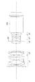
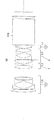
図1から図4は、本発明の数値実施例1から4のレンズ断面図である。前記図1は投射レンズが単焦点レンズの場合を表しており、残りの前記図2から4は投射レンズがズームレンズの場合を各々表している。各図において、拡大共役側がスクリーン側にあたり、縮小共役側が液晶パネル側にあたる。また、各図中のL1からL6は第1レンズ群から第6レンズ群の各レンズ群を表している。各レンズ群の内少なくとも1つのレンズ群に、回折光学素子を少なくとも1つ設けている。SPは絞りであり、各実施例とも第3レンズ群L3、若しくは第4レンズ群L4に存在する。また、GBは色合成プリズム等のガラスブロックである。前記ガラスブロックGBと前記縮小側共役面(液晶パネル面)との間には、拡大共役側に凸面を向けた平凸レンズを、赤・青・緑の各液晶パネル面との間に対して配置している。(但し、図中には1つの平凸レンズのみを表示している。) 前記図2から4において、矢印は広角端から望遠端への変倍を行う際の各レンズ群の移動軌跡を示している。 1 to 4 are lens cross-sectional views of Numerical Examples 1 to 4 of the present invention. FIG. 1 shows a case where the projection lens is a single focus lens, and the remaining FIGS. 2 to 4 show cases where the projection lens is a zoom lens. In each figure, the enlargement conjugate side corresponds to the screen side, and the reduction conjugate side corresponds to the liquid crystal panel side. Further, L1 to L6 in the drawings represent the lens groups of the first lens group to the sixth lens group. At least one diffractive optical element is provided in at least one of the lens groups. SP is a stop, which is present in the third lens unit L3 or the fourth lens unit L4 in each embodiment. GB is a glass block such as a color synthesis prism. Between the glass block GB and the reduction-side conjugate surface (liquid crystal panel surface), a plano-convex lens having a convex surface facing the magnification conjugate side is disposed between each of the red, blue, and green liquid crystal panel surfaces. doing. (However, only one plano-convex lens is shown in the figure.) In FIGS. 2 to 4, the arrows indicate the movement trajectory of each lens group when zooming from the wide-angle end to the telephoto end. Yes.
次に、本発明の各数値実施例を各図に対応させながら説明する。 Next, each numerical example of the present invention will be described with reference to each drawing.
図1の数値実施例1は、拡大共役側より順に、負の屈折力の第1レンズ群L1、正の屈折力の第2レンズ群L2、正の屈折力の第3レンズ群L3、負の屈折力の第4レンズ群L4、正の屈折力の第5レンズ群L5の5群構成の単焦点レンズであり、前記第4レンズ群L4に回折光学素子を導入した例である。レンズ群の群構成として、最も拡大共役側に負レンズ群を配置するのは、全体としてレトロフォーカスの構成をとることで、色合成プリズム等のガラスブロックを配置するのに必要な長いバックフォーカスを得るためである。一方、ガラスブロックGBと縮小側共役面(液晶パネル面)との間に、拡大共役側に凸面を向けた平凸レンズを配置するのは、縮小側共役面(液晶パネル面)に対してテレセントリックにするためであり、且つ前記第5レンズ群L5の最も縮小共役側にある正レンズのレンズ径を小さくすることができ、小型な色合成プリズムにも対応可能であるという利点がある。 In numerical example 1 of FIG. 1, in order from the magnification conjugate side, the first lens unit L1 having a negative refractive power, the second lens unit L2 having a positive refractive power, the third lens unit L3 having a positive refractive power, and a negative lens unit This is a single-focus lens having a five-group configuration including a fourth lens unit L4 having a refractive power and a fifth lens unit L5 having a positive refractive power, and a diffractive optical element is introduced into the fourth lens unit L4. As the lens group configuration, the negative lens group is arranged on the most magnifying conjugate side by adopting a retrofocus configuration as a whole, and has a long back focus necessary for arranging a glass block such as a color synthesis prism. To get. On the other hand, a plano-convex lens with a convex surface facing the magnification conjugate side between the glass block GB and the reduction side conjugate surface (liquid crystal panel surface) is telecentric with respect to the reduction side conjugate surface (liquid crystal panel surface). Therefore, there is an advantage that the lens diameter of the positive lens closest to the reduction conjugate side of the fifth lens unit L5 can be reduced, and it is possible to cope with a small color combining prism.
各レンズ群内のレンズ構成は以下の通りである。 The lens configuration in each lens group is as follows.
前記第1レンズ群L1は、拡大共役側より順に、縮小共役側に凸の正のメニスカスレンズ、拡大共役側に凸の負のメニスカスレンズ、両凹レンズ、縮小共役側に凸の正レンズにより構成されている。前記最も拡大共役側にある縮小共役側に凸の正のメニスカスレンズは、最も軸外の光束が通る位置で歪曲収差の補正を行うために、前記拡大共役側に凸の負のメニスカスレンズは長いバックフォーカスを得るために配置されている。また、前記両凹レンズは、各面の負の屈折力を分散させ、高次の歪曲収差、コマ収差及び非点収差の発生を小さくするために、前記縮小共役側に凸の正レンズは色収差の補正のため配置されている。 The first lens unit L1 includes, in order from the magnification conjugate side, a positive meniscus lens convex on the reduction conjugate side, a negative meniscus lens convex on the magnification conjugate side, a biconcave lens, and a positive lens convex on the reduction conjugate side. ing. The positive meniscus lens convex on the reduction conjugate side closest to the magnification conjugate side is long in the negative meniscus lens convex on the magnification conjugate side in order to correct distortion at the position where the most off-axis light beam passes. Arranged to get back focus. In addition, the biconcave lens disperses the negative refractive power of each surface and reduces the occurrence of high-order distortion, coma and astigmatism. Arranged for correction.
前記第2レンズ群L2は、拡大共役側から順に、強いパワーを有した両凸レンズ、縮小共役側に凸の負のメニスカスレンズにより構成されている。前記縮小共役側に凸の負のメニスカスレンズにより、前記第1レンズ群L1で発生した歪曲収差を補正し、前記第2レンズ群L2内の空気レンズにより、前記第1レンズ群L1で発生した非点収差を補正している。 The second lens unit L2 includes, in order from the magnification conjugate side, a biconvex lens having strong power and a negative meniscus lens convex to the reduction conjugate side. Distortion aberration generated in the first lens unit L1 is corrected by the negative meniscus lens convex to the reduction conjugate side, and non-existence generated in the first lens unit L1 by the air lens in the second lens unit L2. The point aberration is corrected.
前記第3レンズ群L3は、拡大共役側から順に、強いパワーを有した正レンズ、強いパワーを有した負レンズにより構成されている。前記正レンズにより、前記第1レンズ群L1で発生した像面湾曲(ペッツバール和)を打ち消しており、前記負レンズにより、前記第2レンズ群L2内で発生した球面収差を小さくしている。 The third lens unit L3 includes, in order from the magnification conjugate side, a positive lens having strong power and a negative lens having strong power. The positive lens cancels the curvature of field (Petzbar sum) generated in the first lens unit L1, and the negative lens reduces the spherical aberration generated in the second lens unit L2.
前記第4レンズ群L4は、拡大共役側から順に、強いパワーを有した両凹レンズと正レンズから成る接合レンズ、及び縮小共役側に凸の正レンズにより構成されている。前記接合レンズにより、両凹レンズに入射する光線を跳ね上げ、長いバックフォーカスを得ている。また、前記接合レンズは、前記第3レンズ群L3で発生した非点収差を打ち消している。前記縮小共役側に凸の正レンズは、軸上及び軸外の光束の屈折を分散させる働きをしている。 The fourth lens unit L4 includes, in order from the magnification conjugate side, a cemented lens including a biconcave lens having a strong power and a positive lens, and a positive lens convex to the reduction conjugate side. The cemented lens jumps up the light incident on the biconcave lens and obtains a long back focus. Further, the cemented lens cancels astigmatism generated in the third lens unit L3. The positive lens convex on the reduction conjugate side functions to disperse the refraction of the on-axis and off-axis light beams.
前記第5レンズ群L5は、強いパワーを有した1枚の両凸レンズにより構成されている。前記第1レンズ群L1から前記第4レンズ群L4の合成主平面と第5レンズ群L5の実際に光線が屈折される点の距離を、光軸から離れた位置程大きくすることができるので、周辺の光路程合成屈折力を弱めることができ、拡大共役面(スクリーン面)上での糸巻き型の歪曲を減少させることができる。 The fifth lens unit L5 is composed of one biconvex lens having strong power. Since the distance from the first principal lens unit L1 to the synthetic main plane of the fourth lens unit L4 and the point where the light beam is actually refracted in the fifth lens unit L5 can be increased as the position is away from the optical axis, The combined optical power of the surrounding optical path can be weakened, and the pincushion type distortion on the enlarged conjugate surface (screen surface) can be reduced.
ガラスブロックGBと縮小側共役面(液晶パネル面)との間に配置された、拡大共役側に凸面を向けた平凸レンズは、縮小側共役面(液晶パネル面)に対してテレセントリックにする働きがあり、且つ前記第5レンズ群L5の両凸レンズのレンズ径を小さくすることができ、小型な色合成プリズム(ガラスブロックGB)に対応可能としている。また、前記第1レンズ群L1から前記第5レンズ群L5で発生した歪曲収差を補正する役目も果たしている。 A plano-convex lens with a convex surface facing the enlargement conjugate side, placed between the glass block GB and the reduction side conjugate surface (liquid crystal panel surface), works to make it telecentric with respect to the reduction side conjugate surface (liquid crystal panel surface). In addition, the lens diameter of the biconvex lens of the fifth lens unit L5 can be reduced, and it is possible to cope with a small color synthesis prism (glass block GB). It also plays a role of correcting distortion aberration generated from the first lens unit L1 to the fifth lens unit L5.
尚、絞りは前記第3レンズ群L3にあり、前記第1レンズ群L1を移動させてフォーカスを行っている。 The stop is in the third lens unit L3, and focusing is performed by moving the first lens unit L1.
図2の数値実施例2は、拡大共役側より順に、負の屈折力の第1レンズ群L1、正の屈折力の第2レンズ群L2、正の屈折力の第3レンズ群L3、正の屈折力の第4レンズ群L4の4群構成のズームレンズであり、前記第3レンズ群L3に回折光学素子を導入した例である。 In numerical example 2 of FIG. 2, in order from the magnification conjugate side, the first lens unit L1 having a negative refractive power, the second lens unit L2 having a positive refractive power, the third lens unit L3 having a positive refractive power, and a positive lens unit This is a zoom lens having a four-group configuration of the fourth lens unit L4 having refractive power, and a diffractive optical element is introduced into the third lens unit L3.
各レンズ群内のレンズ構成は以下の通りである。 The lens configuration in each lens group is as follows.
前記第1レンズ群L1は、拡大共役側から順に、両凸レンズ、拡大共役側に凸の負のメニスカスレンズ、両凹レンズ、両凸レンズにより構成されている。前記最も拡大共役側にある両凸レンズは、最も軸外の光束が通る位置で歪曲収差の補正を行うために、前記拡大共役側に凸の負のメニスカスレンズは長いバックフォーカスを得るために配置されている。また、前記両凹レンズは、各面の負の屈折力を分散させ、高次の歪曲収差、コマ収差及び非点収差の発生を小さくするために、前記両凸レンズは色収差の補正のため配置されている。 The first lens unit L1 includes, in order from the magnification conjugate side, a biconvex lens, a negative meniscus lens convex to the magnification conjugate side, a biconcave lens, and a biconvex lens. The biconvex lens closest to the magnification conjugate side corrects distortion at the position where the most off-axis light beam passes, and the negative meniscus lens convex toward the magnification conjugate side is arranged to obtain a long back focus. ing. The biconcave lens is arranged for correcting chromatic aberration in order to disperse the negative refractive power of each surface and reduce the occurrence of higher-order distortion, coma and astigmatism. Yes.
前記第2レンズ群L2は、拡大共役側から順に、両凸レンズと縮小共役側に凸の負のメニスカスレンズを貼り合せた接合レンズにより構成されている。前記接合レンズにより、前記第1レンズ群L1で発生した歪曲収差を打ち消している。 The second lens unit L2 includes a cemented lens in which a biconvex lens and a convex negative meniscus lens are bonded to the reduction conjugate side in order from the enlargement conjugate side. The cemented lens cancels the distortion generated in the first lens unit L1.
前記第3レンズ群L3は、拡大共役側から順に、拡大共役側に強いパワーを有した正レンズ、両凹レンズ、強いパワーを有した両凹レンズと強いパワーを有した両凸レンズから成る接合レンズにより構成されている。前記最も拡大共役側にある正レンズにより、前記第2レンズ群L2で発生したコマ収差、及び非点収差を打ち消しており、前記両凹レンズにより、前記第2レンズ群L2内で発生した球面収差を打ち消してしている。前記接合レンズにより、両凹レンズに入射する光線を跳ね上げ、長いバックフォーカスを得ている。また、前記接合レンズは、前記第2レンズ群L2で発生したコマ収差を打ち消す働きをしている。 The third lens unit L3 includes, in order from the magnification conjugate side, a cemented lens including a positive lens having strong power on the magnification conjugate side, a biconcave lens, a biconcave lens having strong power, and a biconvex lens having strong power. Has been. The coma aberration and astigmatism generated in the second lens group L2 are canceled out by the positive lens closest to the magnification conjugate side, and the spherical aberration generated in the second lens group L2 is canceled out by the biconcave lens. It has been countered. The cemented lens jumps up the light incident on the biconcave lens and obtains a long back focus. Further, the cemented lens functions to cancel coma generated in the second lens unit L2.
前記第4レンズ群L4は、拡大共役側に凸の1枚の正レンズにより構成されている。前記第1レンズ群L1から前記第3レンズ群L3の合成主平面と第4レンズ群L4の実際に光線が屈折される点の距離を、光軸から離れた位置程大きくすることができるので、周辺の光路程合成屈折力を弱めることができ、拡大側共役面(スクリーン面)上での糸巻き型の歪曲を減少させることができる。 The fourth lens unit L4 includes a single positive lens convex on the magnification conjugate side. The distance between the first principal lens unit L1 and the third principal lens unit L3 and the fourth lens unit L4 can be increased as the distance from the optical axis increases. The combined optical power of the peripheral optical path can be weakened, and the pincushion type distortion on the enlargement side conjugate surface (screen surface) can be reduced.
ガラスブロックGBと縮小側共役面(液晶パネル面)との間に配置された、拡大共役側に凸面を向けた平凸レンズは、縮小側共役面(液晶パネル面)に対してテレセントリックにする働きがあり、且つ前記第4レンズ群L4の両凸レンズのレンズ径を小さくすることができ、小型な色合成プリズム(ガラスブロックGB)に対応可能としている。また、前記第1レンズ群L1から前記第4レンズ群L4で発生した歪曲収差を補正する役目も果たしている。 A plano-convex lens with a convex surface facing the enlargement conjugate side, placed between the glass block GB and the reduction side conjugate surface (liquid crystal panel surface), works to make it telecentric with respect to the reduction side conjugate surface (liquid crystal panel surface). In addition, it is possible to reduce the lens diameter of the biconvex lens of the fourth lens unit L4, and it is possible to cope with a small color synthesis prism (glass block GB). It also plays a role of correcting distortion aberration generated from the first lens unit L1 to the fourth lens unit L4.
広角端から望遠端への変倍に際しては、前記第1レンズ群L1及び第4レンズ群L4は固定であり、前記第2レンズ群L2、前記第3レンズ群L3は縮小共役側から拡大共役側へ移動している。尚、絞りは前記第3レンズ群L3にあり、前記第1レンズ群L1を移動させてフォーカスを行っている。 When zooming from the wide-angle end to the telephoto end, the first lens unit L1 and the fourth lens unit L4 are fixed, and the second lens unit L2 and the third lens unit L3 are from the reduction conjugate side to the enlargement conjugate side. Has moved to. The stop is in the third lens unit L3, and focusing is performed by moving the first lens unit L1.
図3の数値実施例3は、拡大共役側より順に、負の屈折力の第1レンズ群L1、正の屈折力の第2レンズ群L2、負の屈折力の第3レンズ群L3、正の屈折力の第4レンズ群L4、正の屈折力の第5レンズ群L5の5群構成のズームレンズであり、前記第4レンズ群L4に回折光学素子を導入した例である。 In numerical example 3 of FIG. 3, in order from the magnification conjugate side, the first lens unit L1 having a negative refractive power, the second lens unit L2 having a positive refractive power, the third lens unit L3 having a negative refractive power, and a positive lens unit In this example, the zoom lens has a five-group configuration including a fourth lens unit L4 having a refractive power and a fifth lens unit L5 having a positive refractive power, and a diffractive optical element is introduced into the fourth lens unit L4.
各レンズ群内のレンズ構成は以下の通りである。 The lens configuration in each lens group is as follows.
前記第1レンズ群L1は、拡大共役側から順に、縮小共役側に強いパワーを持った正レンズ、拡大共役側に凸の負のメニスカスレンズ、強いパワーを有した両凹レンズ、両凸レンズにより構成されている。前記最も拡大共役側にある縮小共役側に強いパワーを持った正レンズは、最も軸外の光束が通る位置で歪曲収差の補正を行うために、前記拡大共役側に凸の負のメニスカスレンズは長いバックフォーカスを得るために配置されている。また、前記両凹レンズは、各面の負の屈折力を分散させ、高次の歪曲収差、コマ収差及び非点収差の発生を小さくするために、前記両凸レンズは色収差の補正のため配置されている。 The first lens unit L1 includes, in order from the magnification conjugate side, a positive lens having strong power on the reduction conjugate side, a negative meniscus lens convex on the magnification conjugate side, a biconcave lens having strong power, and a biconvex lens. ing. The positive meniscus lens having a strong power on the reduction conjugate side closest to the magnification conjugate side corrects distortion at the position where the most off-axis light beam passes, so that the negative meniscus lens convex on the magnification conjugate side is Arranged for long back focus. The biconcave lens is arranged for correcting chromatic aberration in order to disperse the negative refractive power of each surface and reduce the occurrence of higher-order distortion, coma and astigmatism. Yes.
前記第2レンズ群L2は、拡大共役側から順に、強いパワーを有した両凸レンズ、縮小共役側に凸の負のメニスカスレンズにより構成されている。前記縮小共役側に凸の負のメニスカスレンズにより、前記第1レンズ群L1で発生した歪曲収差を補正し、前記第2レンズ群L2内の空気レンズ及び前記強いパワーを有した両凸レンズにより、前記第1レンズ群L1で発生した像面湾曲収差(ペッツバール和)を補正している。 The second lens unit L2 includes, in order from the magnification conjugate side, a biconvex lens having strong power and a negative meniscus lens convex to the reduction conjugate side. The negative meniscus lens convex on the reduction conjugate side corrects distortion aberration generated in the first lens unit L1, and the air lens in the second lens unit L2 and the biconvex lens having the strong power The field curvature aberration (Petzbar sum) generated in the first lens unit L1 is corrected.
前記第3レンズ群L3は、拡大共役側から順に、拡大共役側に凸の弱いパワーを有した正のメニスカスレンズ、拡大共役側に凸の負のメニスカスレンズにより構成されている。前記正のメニスカスレンズにより、前記第1レンズ群L1及び前記第2レンズ群L2で発生した非点収差を打ち消しており、一方、前記負のメニスカスレンズにより、前記第2レンズ群L2内で発生した球面収差を打ち消してしている。 The third lens unit L3 includes, in order from the magnification conjugate side, a positive meniscus lens having a weak convex power on the magnification conjugate side and a negative meniscus lens convex on the magnification conjugate side. The positive meniscus lens cancels the astigmatism generated in the first lens group L1 and the second lens group L2, while the negative meniscus lens generates in the second lens group L2. The spherical aberration is canceled out.
前記第4レンズ群L4は、拡大共役側から順に、強いパワーを有した両凹レンズと強いパワーを有した両凸レンズから成る接合レンズにより構成されている。前記接合レンズの両凹レンズにより、入射する光線を跳ね上げ、長いバックフォーカスを得ている。また、前記接合レンズは、前記第3レンズ群L3で発生したコマ収差、及び前記第2レンズ群L2で発生した非点収差を打ち消している。 The fourth lens unit L4 includes, in order from the magnification conjugate side, a cemented lens including a biconcave lens having strong power and a biconvex lens having strong power. The biconcave lens of the cemented lens jumps up the incident light beam and obtains a long back focus. Further, the cemented lens cancels coma aberration generated in the third lens group L3 and astigmatism generated in the second lens group L2.
前記第5レンズ群L5は、拡大共役側に凸の1枚の正レンズにより構成されている。前記第1レンズ群L1から前記第4レンズ群L4の合成主平面と前記第5レンズ群L5の実際に光線が屈折される点の距離を、光軸から離れた位置程大きくすることができるので、周辺の光路程合成屈折力を弱めることができ、拡大側共役面(スクリーン面)上での糸巻き型の歪曲を減少させることができる。 The fifth lens unit L5 includes a single positive lens convex on the magnification conjugate side. Since the distance from the first principal lens unit L1 to the synthetic main plane of the fourth lens unit L4 and the point where the light beam is actually refracted by the fifth lens unit L5 can be increased as the distance from the optical axis increases. The combined optical power of the peripheral optical path can be weakened, and the pincushion type distortion on the enlargement side conjugate surface (screen surface) can be reduced.
ガラスブロックGBと縮小側共役面(液晶パネル面)との間に配置された、拡大共役側に凸面を向けた平凸レンズは、縮小側共役面(液晶パネル面)に対してテレセントリックにする働きがあり、且つ前記第5レンズ群L5の両凸レンズのレンズ径を小さくすることができ、小型な色合成プリズム(ガラスブロックGB)に対応可能としている。また、前記第1レンズ群L1から前記第5レンズ群L5で発生した歪曲収差を補正する役目も果たしている。 A plano-convex lens with a convex surface facing the enlargement conjugate side, placed between the glass block GB and the reduction side conjugate surface (liquid crystal panel surface), works to make it telecentric with respect to the reduction side conjugate surface (liquid crystal panel surface). In addition, the lens diameter of the biconvex lens of the fifth lens unit L5 can be reduced, and it is possible to cope with a small color synthesis prism (glass block GB). It also plays a role of correcting distortion aberration generated from the first lens unit L1 to the fifth lens unit L5.
広角端から望遠端への変倍に際しては、前記第1レンズ群L1及び第5レンズ群L5は固定であり、前記第2レンズ群L2、前記第3レンズ群L3、前記第4レンズ群L4は縮小共役側から拡大共役側へ移動している。尚、絞りは前記第3レンズ群L3にあり、前記第1レンズ群L1を移動させてフォーカスを行っている。 During zooming from the wide-angle end to the telephoto end, the first lens unit L1 and the fifth lens unit L5 are fixed, and the second lens unit L2, the third lens unit L3, and the fourth lens unit L4 are It moves from the reduction conjugate side to the enlargement conjugate side. The stop is in the third lens unit L3, and focusing is performed by moving the first lens unit L1.
図4の数値実施例4は、拡大共役側より順に、負の屈折力の第1レンズ群L1、正の屈折力の第2レンズ群L2、正の屈折力の第3レンズ群L3、負の屈折力の第4レンズ群L4、正の屈折力の第5レンズ群L5、正の屈折力の第6レンズ群L6の6群構成のズームレンズであり、前記第5レンズ群L5に回折光学素子を導入した例である。 In numerical example 4 of FIG. 4, in order from the magnification conjugate side, the first lens unit L1 having a negative refractive power, the second lens unit L2 having a positive refractive power, the third lens unit L3 having a positive refractive power, and a negative The zoom lens has a six-group configuration including a fourth lens unit L4 having a refractive power, a fifth lens unit L5 having a positive refractive power, and a sixth lens unit L6 having a positive refractive power, and includes a diffractive optical element in the fifth lens unit L5. This is an example of introducing.
各レンズ群内のレンズ構成は以下の通りである。 The lens configuration in each lens group is as follows.
前記第1レンズ群L1は、拡大共役側から順に、縮小共役側に強いパワーを持った正レンズ、拡大共役側に凸の負のメニスカスレンズ、強いパワーを有した両凹レンズ、両凸レンズにより構成されている。前記最も拡大共役側にある縮小共役側に強いパワーを持った正レンズは、最も軸外の光束が通る位置で歪曲収差の補正を行うために、前記拡大共役側に凸の負のメニスカスレンズは長いバックフォーカスを得るために配置されている。また、前記両凹レンズは、各面の負の屈折力を分散させ、高次の歪曲収差、コマ収差及び非点収差の発生を小さくするために、前記両凸レンズは色収差の補正のため配置されている。 The first lens unit L1 includes, in order from the magnification conjugate side, a positive lens having strong power on the reduction conjugate side, a negative meniscus lens convex on the magnification conjugate side, a biconcave lens having strong power, and a biconvex lens. ing. The positive meniscus lens having a strong power on the reduction conjugate side closest to the magnification conjugate side corrects distortion at the position where the most off-axis light beam passes, so that the negative meniscus lens convex on the magnification conjugate side is Arranged for long back focus. The biconcave lens is arranged for correcting chromatic aberration in order to disperse the negative refractive power of each surface and reduce the occurrence of higher-order distortion, coma and astigmatism. Yes.
前記第2レンズ群L2は、拡大共役側から順に、強いパワーを有した両凸レンズ、縮小共役側に凸の負のメニスカスレンズにより構成されている。前記縮小共役側に凸の負のメニスカスレンズにより、前記第1レンズ群L1で発生した歪曲収差を補正し、前記第2レンズ群L2内の空気レンズ及び前記強いパワーを有した両凸レンズにより、前記第1レンズ群L1で発生した像面湾曲収差(ペッツバール和)を補正している。 The second lens unit L2 includes, in order from the magnification conjugate side, a biconvex lens having strong power and a negative meniscus lens convex to the reduction conjugate side. The negative meniscus lens convex on the reduction conjugate side corrects distortion aberration generated in the first lens unit L1, and the air lens in the second lens unit L2 and the biconvex lens having the strong power The field curvature aberration (Petzbar sum) generated in the first lens unit L1 is corrected.
前記第3レンズ群L3は、拡大共役側に凸の弱いパワーを有した1枚の正のメニスカスレンズにより構成されている。前記正のメニスカスレンズは、前記第3レンズ群L3内で発生する球面収差を小さくするような形状となっている。 The third lens unit L3 is composed of one positive meniscus lens having convex weak power on the magnification conjugate side. The positive meniscus lens is shaped to reduce spherical aberration that occurs in the third lens unit L3.
前記第4レンズ群L4は、1枚の両凹レンズにより構成されている。前記両凹レンズにより、前記第2レンズ群L2で発生した球面収差及び非点収差を打ち消す働きをしている。 The fourth lens unit L4 is composed of one biconcave lens. The biconcave lens serves to cancel the spherical aberration and astigmatism generated in the second lens unit L2.
前記第5レンズ群L5は、拡大共役側から順に、強いパワーを有した両凹レンズと強いパワーを有した両凸レンズから成る接合レンズにより構成されている。前記接合レンズの両凹レンズにより、入射する光線を跳ね上げ、長いバックフォーカスを得ている。また、前記接合レンズは、前記第4レンズ群L4で発生したコマ収差、前記第3レンズ群L3で発生した非点収差、及び前記第4レンズ群L4で発生した歪曲収差を打ち消している。 The fifth lens unit L5 includes, in order from the magnification conjugate side, a cemented lens including a biconcave lens having strong power and a biconvex lens having strong power. The biconcave lens of the cemented lens jumps up the incident light beam and obtains a long back focus. Further, the cemented lens cancels coma aberration generated in the fourth lens group L4, astigmatism generated in the third lens group L3, and distortion aberration generated in the fourth lens group L4.
前記第6レンズ群L6は、拡大共役側に凸の1枚の正レンズにより構成されている。前記第1レンズ群L1から前記第5レンズ群L5の合成主平面と前記第6レンズ群L6の実際に光線が屈折される点の距離を、光軸から離れた位置程大きくすることができるので、周辺の光路程合成屈折力を弱めることができ、拡大側共役面(スクリーン面)上での糸巻き型の歪曲を減少させることができる。 The sixth lens group L6 includes a single positive lens convex on the magnification conjugate side. Since the distance from the first lens unit L1 to the combined principal plane of the fifth lens unit L5 and the point where the light beam is actually refracted by the sixth lens unit L6 can be increased as the position is away from the optical axis. The combined optical power of the peripheral optical path can be weakened, and the pincushion type distortion on the enlargement side conjugate surface (screen surface) can be reduced.
ガラスブロックGBと縮小側共役面(液晶パネル面)との間に配置された、拡大共役側に凸面を向けた平凸レンズは、縮小側共役面(液晶パネル面)に対してテレセントリックにする働きがあり、且つ前記第6レンズ群L6の両凸レンズのレンズ径を小さくすることができ、小型な色合成プリズム(ガラスブロックGB)に対応可能としている。また、前記第1レンズ群L1から前記第6レンズ群L6で発生した歪曲収差を補正する役目も果たしている。 A plano-convex lens with a convex surface facing the enlargement conjugate side, placed between the glass block GB and the reduction side conjugate surface (liquid crystal panel surface), works to make it telecentric with respect to the reduction side conjugate surface (liquid crystal panel surface). In addition, the lens diameter of the biconvex lens of the sixth lens unit L6 can be reduced, and it is possible to cope with a small color synthesis prism (glass block GB). Also, it plays a role of correcting distortion aberration generated from the first lens unit L1 to the sixth lens unit L6.
広角端から望遠端への変倍に際しては、前記第1レンズ群L1及び第6レンズ群L6は固定であり、前記第2レンズ群L2、前記第3レンズ群L3、前記第4レンズ群L4、前記第5レンズ群L5は縮小共役側から拡大共役側へ移動している。尚、絞りは前記第4レンズ群L4にあり、前記第1レンズ群L1を移動させてフォーカスを行っている。 During zooming from the wide-angle end to the telephoto end, the first lens group L1 and the sixth lens group L6 are fixed, and the second lens group L2, the third lens group L3, the fourth lens group L4, The fifth lens unit L5 moves from the reduction conjugate side to the enlargement conjugate side. The stop is in the fourth lens unit L4, and focusing is performed by moving the first lens unit L1.
以上のようなレンズ構成を取ることにより、本発明に係る色合成投射光学系を達成することができる。 By adopting the lens configuration as described above, the color synthesis projection optical system according to the present invention can be achieved.
更に諸収差の補正が十分になされ、レンズ構成が簡易で且つレンズ全長が短縮された色合成投射光学系を達成するためには、以下の条件式を満足することが望ましい。 Furthermore, in order to achieve a color composition projection optical system in which various aberrations are sufficiently corrected, the lens configuration is simple, and the total lens length is shortened, it is desirable to satisfy the following conditional expression.
前記色合成投射光学系において、前記色合成プリズムと前記画像変調装置との間に配置されている全体として正の屈折力のレンズ群と前記投射レンズとの間に、以下の条件式を満足することである。 In the color synthesis projection optical system, the following conditional expression is satisfied between the projection lens and the lens group having a positive refractive power as a whole arranged between the color synthesis prism and the image modulation device. That is.
0.3 < b.f./ f P-I < 0.8 ……………(1)
ここで、b.f.は拡大共役側の共役点が無限大時の縮小共役側のバックフォーカス(ここにおけるb.f.の値は、前記投射レンズと縮小共役点の間に配置されたプリズム等のガラスブロックを空気に換算した際の値)であり、f P-Iは前記色合成プリズムと前記画像変調装置との間に配置されている全体として正の屈折力のレンズ群の焦点距離を表している。
0.3 <b. f. / f PI <0.8 …………… (1)
Where b. f. Is the back focus on the reduction conjugate side when the conjugate point on the enlargement conjugate side is infinite (the value of bf here is the air flow through a glass block such as a prism disposed between the projection lens and the reduction conjugate point) F PI represents the focal length of the lens unit having a positive refractive power as a whole disposed between the color synthesizing prism and the image modulation device.
条件式(1)は、前記色合成プリズムと前記画像変調装置との間に配置されている全体として正の屈折力のレンズ群と拡大共役側の共役点が無限大時の縮小共役側のバックフォーカスに関するものである。条件式(1)の下限値を超えると、色合成プリズムを配置する空間が十分に取れなくなるので好ましくない。条件式(1)の上限値を超えると、前記色合成プリズムと前記画像変調装置との間に配置されている全体として正の屈折力のレンズ群の焦点距離が強くなり過ぎ、光学性能を良好に保つことが困難になり好ましくない。 Conditional expression (1) indicates that the lens group having a positive refractive power as a whole disposed between the color synthesizing prism and the image modulation device and the reduction conjugate side back when the conjugate point on the enlargement conjugate side is infinite. Concerning focus. Exceeding the lower limit of conditional expression (1) is not preferable because a sufficient space for the color synthesis prism cannot be obtained. When the upper limit value of conditional expression (1) is exceeded, the focal length of the lens unit having a positive refractive power as a whole disposed between the color synthesizing prism and the image modulation device becomes too strong, and the optical performance is good. It is difficult to keep it at a low level, which is not preferable.
更に、上記条件式(1)を満足した上で、前記色合成投射光学系における縮小共役側の瞳位置が以下の条件式を満足することが望ましい。 Furthermore, it is desirable that the pupil position on the reduction conjugate side in the color synthesis projection optical system satisfies the following conditional expression while satisfying the conditional expression (1).
全系の焦点距離(前記投射レンズがズームレンズの場合、広角端における全系の焦点距離)をfw、縮小共役側の瞳位置(縮小側共役点と縮小共役側の瞳位置との間の距離;前記投射レンズがズームレンズの場合、広角端における縮小共役側の瞳位置)をtkwとした際、以下の条件式を満足していることである。 The focal length of the entire system (when the projection lens is a zoom lens, the focal length of the entire system at the wide-angle end) is fw, and the pupil position on the reduction conjugate side (the distance between the reduction conjugate point and the reduction conjugate side pupil position) When the projection lens is a zoom lens, the following conditional expression is satisfied when tkw is set as the reduction conjugate side pupil position at the wide-angle end.
0.10 < |fw / tkw| < 0.20 …………(2)
条件式(2)は、全系の焦点距離と縮小共役側の瞳位置に関するものである。条件式(2)の下限値を超えると、前記色合成プリズムと前記画像変調装置との間に配置されている全体として正の屈折力のレンズ群の焦点距離が強くなり過ぎ、光学性能を良好に保つことが困難になり好ましくない。条件式(2)の上限値を超えると、縮小側共役面(液晶パネル面)に対してテレセントリック性が良くなくなるので好ましくない。
0.10 <| fw / tkw | <0.20 (2)
Conditional expression (2) relates to the focal length of the entire system and the pupil position on the reduction conjugate side. If the lower limit value of conditional expression (2) is exceeded, the focal length of the lens unit having a positive refractive power as a whole disposed between the color synthesizing prism and the image modulation device becomes too strong, and the optical performance is good. It is difficult to keep it at a low level, which is not preferable. Exceeding the upper limit of conditional expression (2) is not preferable because the telecentricity with respect to the reduction-side conjugate surface (liquid crystal panel surface) becomes poor.
以上のような構成にすることで、本発明に関する課題を達成することかできる。 With the configuration as described above, the problems related to the present invention can be achieved.
本実施形態において、回折光学素子を設ける面に関しては、各光学系を通過する軸上光線及び軸外光線が、各光線入射位置における法線方向に対して角度に差が生じると、回折効率が劣化することが懸念される為、前記軸上光線及び軸外光線に対して、できるだけコンセントリックなレンズ面に設定することが好ましい。 In the present embodiment, with respect to the surface on which the diffractive optical element is provided, if the axial ray and off-axis ray passing through each optical system have a difference in angle with respect to the normal direction at each ray incident position, the diffraction efficiency is increased. Since there is concern about deterioration, it is preferable to set the lens surface as concentric as possible with respect to the on-axis light and the off-axis light.
また、最も外側の面には、収差補正上やむを得ない等の特別な場合を除いて配置しない方が好ましい。これは、回折光学素子はかなり狭い幅の溝(数ミクロンあるいはサブミクロンオーダーの幅の溝)で構成されており、塵等から前記光学素子表面を保護するためには、最も外側に配置しない方が好ましいためである。 Further, it is preferable that the outermost surface is not disposed except in special cases such as unavoidable in terms of aberration correction. This is because the diffractive optical element is composed of a groove having a fairly narrow width (a groove having a width of several microns or a submicron order), and is not arranged on the outermost side in order to protect the surface of the optical element from dust or the like. Is preferable.
更に本実施形態において、回折光学素子を導入する位置として、以下の条件を満足する位置に前記回折光学素子を導入すると、色収差の補正上好ましい。 Further, in the present embodiment, it is preferable to introduce the diffractive optical element at a position satisfying the following conditions as a position where the diffractive optical element is introduced from the viewpoint of correcting chromatic aberration.
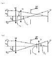
ここで、前記回折光学素子を導入する位置の検討を行うにあたって、問題を簡単に取り扱うために、図201(a)及び図201(b)のような薄肉単レンズで構成された近軸配置を考えることにする。前記図201(a)は前記回折光学素子Dが絞りSPより拡大共役側に配置された場合を、前記図201(b)は前記回折光学素子Dが絞りSPより縮小共役側に配置された場合を各々表している。また各図中のMは光学系を構成する屈折光学系の部分を、Dは回折光学素子を、Pは近軸軸上光線を、Qは瞳近軸光線を、IPは像面を各々表している。 Here, in examining the position where the diffractive optical element is introduced, in order to easily handle the problem, a paraxial arrangement configured with a thin single lens as shown in FIGS. 201 (a) and 201 (b) is used. I will think about it. FIG. 201 (a) shows the case where the diffractive optical element D is arranged on the enlargement conjugate side from the stop SP, and FIG. 201 (b) shows the case where the diffractive optical element D is arranged on the reduction conjugate side from the stop SP. Respectively. In each figure, M represents a refractive optical system part constituting the optical system, D represents a diffractive optical element, P represents a paraxial ray, Q represents a pupil paraxial ray, and IP represents an image plane. ing.
前記屈折光学系(薄肉単レンズ)と回折光学素子から成る光学配置(図201(a)、(b))において、この光学系の軸上色収差係数(L)及び倍率色収差係数(T)は以下の関係式が成り立つ。 In the optical arrangement consisting of the refractive optical system (thin single lens) and the diffractive optical element (FIGS. 201 (a) and (b)), the axial chromatic aberration coefficient (L) and lateral chromatic aberration coefficient (T) of this optical system are as follows: The following relational expression holds.
液晶プロジェクタ等に使用する投影用の屈折光学系の色収差は、一般的に軸上及び倍率色収差ともに正側に発生する傾向にあることから、この場合の屈折光学系全系の軸上色収差係数及び倍率色収差係数ともに、前記(c)式より負の値になる。すなわち、前記(a)式及び(b)式において、 In general, the chromatic aberration of the refractive optical system for projection used in a liquid crystal projector or the like tends to occur on the positive side in both axial and lateral chromatic aberrations. Both the lateral chromatic aberration coefficients are negative values from the equation (c). That is, in the formula (a) and the formula (b),
この屈折光学系で発生した軸上及び倍率色収差の補正をするには、3次収差係数のレベルで考えると、前記屈折光学系と回折光学素子より成る光学系の全系の各色収差係数L、T(前記(a)、(b)式の左辺)の値が各々0に近づけば良いことになる。前述より、屈折光学系部分の軸上色収差係数及び倍率色収差係数ともに負の値であること((d)式)と、前記(a)、(b)式を考慮し、前記全系(屈折光学系部分+回折光学素子)の各色収差係数L、Tの値を0に近づけるには、前記回折光学素子の軸上色収差係数及び倍率色収差係数とも正の値にすれば良い。すなわち、前記(a)式及び(b)式において、 In order to correct on-axis and lateral chromatic aberration generated in this refractive optical system, considering the level of the third-order aberration coefficient, each chromatic aberration coefficient L of the entire optical system consisting of the refractive optical system and the diffractive optical element, The values of T (the left sides of the above expressions (a) and (b)) should be close to 0, respectively. From the above, considering that both the axial chromatic aberration coefficient and the lateral chromatic aberration coefficient of the refractive optical system part are negative values (equation (d)) and the above-mentioned expressions (a) and (b), the entire system (refractive optics) In order to make the values of the chromatic aberration coefficients L and T of the system part + diffractive optical element close to 0, both the axial chromatic aberration coefficient and the lateral chromatic aberration coefficient of the diffractive optical element may be set to positive values. That is, in the above formula (a) and formula (b),
ここで、図201(a)のように、前記回折光学素子Dが絞りSPよりも拡大共役側に配置された場合を考える。この時、回折光学素子Dの位置において、 Here, consider the case where the diffractive optical element D is arranged on the magnification conjugate side with respect to the stop SP as shown in FIG. 201 (a). At this time, at the position of the diffractive optical element D,
一方、図201(b)のように、前記回折光学素子Dが絞りSPよりも縮小共役側に配置された場合を考えると、回折光学素子Dの位置において、 On the other hand, as shown in FIG. 201 (b), when the diffractive optical element D is arranged on the reduction conjugate side with respect to the stop SP, at the position of the diffractive optical element D,
以上のことを、本発明の各実施例について対応させると、各実施例とも、絞りよりも縮小共役側にあるレンズ群、つまり第3レンズ群、第4レンズ群、第5レンズ群、第6レンズ群のいずれかのレンズ群に回折光学素子を導入すれば、軸上色収差及び倍率色収差の両者の色収差を同時に補正する方向にあり好ましい。また、その中でも、前記回折光学素子を設ける面は、前記近軸軸上光線と瞳近軸光線の光軸からの高さができるだけ高い部分に配置した方がより色収差の補正に効果があることから(前記(a)、(e)式及び図201(b)より)、できるだけ縮小共役側に近いレンズ群に設けた方が好ましいことと、できるだけコンセントリックなレンズ面であることが好ましいことと、最も外側のレンズ面は塵や光源からの熱の影響を受けるためなるべく避けた方が良いこと等を考慮すると、実施例1では第4レンズ群内に、実施例2では第3レンズ群内に、実施例3では第4レンズ群内に、実施例4では第5レンズ群内に各々導入することが好ましい。 When the above is made to correspond to each embodiment of the present invention, in each embodiment, the lens group located on the reduction conjugate side with respect to the stop, that is, the third lens group, the fourth lens group, the fifth lens group, the sixth lens group, and the like. It is preferable to introduce a diffractive optical element into any one of the lens groups because it is in the direction of simultaneously correcting both chromatic aberration of axial chromatic aberration and lateral chromatic aberration. Among them, the surface on which the diffractive optical element is provided is more effective in correcting chromatic aberration if it is arranged at a portion where the height from the optical axis of the paraxial light beam and pupil paraxial light beam is as high as possible. (From the formulas (a) and (e) and FIG. 201 (b)), it is preferable that the lens group is as close to the reduction conjugate side as possible, and that the lens surface is as concentric as possible. In consideration of the fact that the outermost lens surface should be avoided as much as possible because it is affected by dust and heat from the light source, it is within the fourth lens group in Example 1, and in the third lens group in Example 2. In addition, it is preferable that the lens is introduced into the fourth lens group in the third embodiment and the fifth lens group in the fourth embodiment.
これらの回折光学素子は、光学面の上に施されるのであるが、そのベースは球面若しくは平面あるいは非球面あるいは2次曲面でも良い。また、それらの光学面にプラスチック等の膜を上記回折光学面として添付する方法(いわゆるレプリカ非球面)で作成しても良い。 These diffractive optical elements are provided on an optical surface, but their base may be a spherical surface, a flat surface, an aspheric surface, or a quadratic surface. Further, it may be formed by a method (so-called replica aspherical surface) in which a film such as plastic is attached to the optical surfaces as the diffractive optical surface.
本実施形態における回折光学素子の製法としては、バイナリオプティクス形状をフォトレジストにより直接レンズ表面に成形する方法の他に、この方法によって作成した型を用いるレプリカ成形やモールド成形を行う方法がある。また、鋸状形状のキノフォームにすれば、回折効率が上がり、理想値に近い回折効率が期待できる。 As a manufacturing method of the diffractive optical element in the present embodiment, there is a method of performing replica molding or mold molding using a mold created by this method, in addition to a method of directly molding a binary optics shape on a lens surface with a photoresist. In addition, if a saw-shaped kinoform is used, the diffraction efficiency increases, and a diffraction efficiency close to the ideal value can be expected.
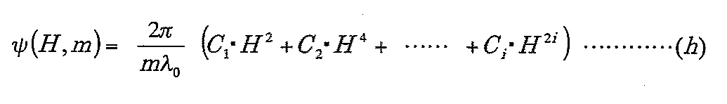
また、本実施形態における回折光学素子の形状ψは、次式によって表される。 In addition, the shape ψ of the diffractive optical element in the present embodiment is expressed by the following equation.
上述の2つ条件式((3)、(4)式)の範囲を外れると、収差補正が難しくなるだけでなく、回折光学素子が作りにくくなり好ましくない。 If the above two conditional expressions (formulas (3) and (4)) are out of the range, not only aberration correction becomes difficult, but also it becomes difficult to produce a diffractive optical element.
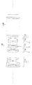
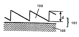
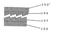
本実施例で用いる回折光学素子の構造としては、図101に示す1層のキノフォーム形状の単層構成のものや、図102に示すような格子厚の異なる(又は同一の)2つの層を積み上げた積層構成のもの等が適用可能である。 As the structure of the diffractive optical element used in this example, a single-layer kinoform-shaped structure shown in FIG. 101, or two layers having different (or the same) grating thickness as shown in FIG. A stacked structure or the like can be applied.
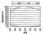
図103は図101に示す回折光学素子101の1次回折光の回折効率の波長依存性を示している。実際の回折光学素子101の構成は、図101より、基材102の表面に紫外線硬化樹脂を塗布し、樹脂部に波長530nmで1次回折光の回折効率が100%となるような格子厚dの回折格子103を形成している。
FIG. 103 shows the wavelength dependence of the diffraction efficiency of the first-order diffracted light of the diffractive
前記図103で明らかなように、設計次数の回折効率は最適化した波長530nmから離れるに従って低下し、一方設計次数近傍の次数の0次回折光と2次回折光の回折効率が増大している。その設計次数以外の回折光の増加はフレアとなり、光学系の解像度の低下につながる。 As is apparent from FIG. 103, the diffraction efficiency of the designed order decreases with increasing distance from the optimized wavelength of 530 nm, while the diffraction efficiency of the 0th order diffracted light and the second order diffracted light near the designed order increases. An increase in the diffracted light other than the design order becomes a flare, which leads to a decrease in the resolution of the optical system.
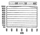
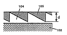
図102に示す2つの回折格子104、105を積層した積層型の回折光学素子の波長依存特性を図104に示す。前記図102では、基材102上に紫外線硬化樹脂(nd=1.499、vd=54)から成る第1の回折格子104を形成し、その上に別の紫外線硬化樹脂(nd=1.598、vd=28)から成る第2の回折格子105を形成している。この材質の組合せでは、第1の回折格子104の格子厚d1はd1=13.8μm、第2の回折格子105の格子厚d2はd2=10.5μmとしている。前記図104から判るように、積層構造の回折光学素子にすることで、設計次数の回折効率は、使用波長全域で95%以上の高い回折効率を有している。
FIG. 104 shows the wavelength dependence characteristics of the laminated diffractive optical element in which the two
このように、本発明の実施例の回折光学素子として積層構造を用いると、光学性能を更に改善することができる。 As described above, when the laminated structure is used as the diffractive optical element of the embodiment of the present invention, the optical performance can be further improved.
なお回折光学素子として、材質を紫外線硬化樹脂に限定するものではなく、他のプラスチック材なども使用できるし、基材によっては第1の回折格子部104を直接基材に形成しても良い。また各格子厚が必ずしも必要はなく、材料の組合せでは図105に示すように2つの格子厚を等しくできる。この場合、回折光学素子表面に格子形状が形成されないので、防塵性に優れ、回折光学素子の組立作業性が向上し、より安価な光学系を提供できる。
The material of the diffractive optical element is not limited to the ultraviolet curable resin, and other plastic materials can be used. Depending on the base material, the first diffraction
また、図106のように、基材102上に紫外線硬化樹脂(nd=1.6685、vd=19.7)から成る第1の回折格子107を形成し、前記回折格子107に対し、互いの鋸の山の部分の間隔を約1.5μm程度離れた場所に、別の紫外線硬化樹脂(nd=1.5240、vd=50.8)から成る第2の回折格子106を形成した積層構造の回折光学素子でも、前記図102の回折格子と同等の回折効率を得ることができる。この材質の組合せでは、第1の回折格子107の格子厚d1はd1=5.0μm、第2の回折格子106の格子厚d2はd2=7.5μmとしている。
Further, as shown in FIG. 106, a
本実施例では、以上のような構成の回折光学素子を用いることによって、色収差を低減でき、レンズ構成が簡易に、且つレンズ全長の短縮化を可能にし、尚且つ良好な光学性能を持つ色合成投射光学系を得ることができた。 In this embodiment, chromatic aberration can be reduced by using the diffractive optical element having the above-described configuration, the lens configuration can be simplified, the overall length of the lens can be shortened, and the color composition has good optical performance. A projection optical system could be obtained.
以下に、本発明の数値実施例を記載する。数値実施例において、riは拡大共役側より順に第i番目のレンズ面の曲率半径、diは拡大共役側より順に第i番目のレンズ厚及び空気間隔、niとviは各々拡大共役側より順に第i番目のレンズのガラス屈折率とアッベ数を表している。 The numerical examples of the present invention will be described below. In numerical examples, ri is the radius of curvature of the i-th lens surface in order from the magnification conjugate side, di is the i-th lens thickness and air spacing in order from the magnification conjugate side, and ni and vi are respectively in order from the magnification conjugate side. It represents the glass refractive index and Abbe number of the i-th lens.
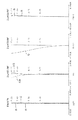
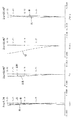
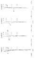
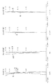
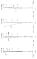
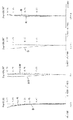
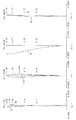
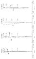
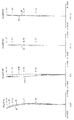
図5は実施例1に対する全系の各収差図を表し、図6〜8、図9〜11、図12〜14は各実施例2〜4に対する広角端、中間位置、望遠端の各収差図を表しており、各図中のB、G、Rは470nm、550nm、650nm、ΔM、ΔSはメリジオナル像面、サジタル像面を示している。 FIG. 5 shows aberration diagrams of the entire system with respect to Example 1. FIGS. 6 to 8, FIGS. 9 to 11, and FIGS. 12 to 14 show aberration diagrams at the wide-angle end, the intermediate position, and the telephoto end with respect to Examples 2 to 4, respectively. In the figures, B, G, and R represent 470 nm, 550 nm, 650 nm, ΔM, and ΔS represent the meridional image surface and the sagittal image surface, respectively.
また、以下に各数値実施例の条件式の値を示す。但し、表中のE-Xは10-Xを表している。 Moreover, the value of the conditional expression of each numerical example is shown below. However, EX in the table represents 10- X .
位相係数 r19面
c1=−6.0290×10⁻⁴
c2=1.0462×10⁻⁶
c3=−2.8418×10⁻⁹
Phase coefficient r19 surface c1 = −6.0290 × 10 −4
c2 = 1.0462 × 10 -6
c3 = −2.8418 × 10 -9
位相係数 r19面
c1=−5.76290×10⁻⁴
c2=3.75000×10⁻⁶
c3=−2.15520×10⁻⁸
Phase coefficient r19 surface c1 = −5.76290 × 10 −4
c2 = 3.75000 × 10 -6
c3 = −2.15520 × 10 −8
位相係数 r19面
c1=−7.43030×10⁻⁴
c2=4.11380×10⁻⁶
c3=−1.25320×10⁻⁸
Phase coefficient r19 surface c1 = −7.43030 × 10 −4
c2 = 4.11380 × 10 -6
c3 = -1.25320 × 10 -8
位相係数 r19面
c1=−6.24480×10⁻⁴
c2=3.17790×10⁻⁶
c3=−8.70150×10⁻⁹
Phase coefficient r19 surface c1 = −6.24480 × 10 −4
c2 = 3.117790 × 10 -6
c3 = −8.70150 × 10 -9
1 光源
2 放物面鏡
3 第1フライアイレンズ
4,9,21,23 反射ミラー
5 第2フライアイレンズ
6 偏光変換素子
7 第1正レンズ
8 青反射ダイクロミラー
10 緑反射ダイクロミラー
11 第2正レンズ
12 青色用画像変調手段
13,16,19 正レンズ
14 第3正レンズ
15 緑色用画像変調手段
17 第6正レンズ
18 赤色用画像変調手段
20 第4正レンズ
22 第5正レンズ
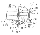
24 第4Aプリズム(第3プリズム)
25 第3Aプリズム
26 第24Aプリズム
27 第1Aプリズム(第1プリズム)
28 投写レンズ
29 第2プリズム
30 プリズム
31,32,33 正レンズ
34 入射面に正レンズが形成された第1プリズム
35 入射面に正レンズが形成された第2プリズム
36 入射面に正レンズが形成された第3プリズム
CSP,CSP1,CSP2 色合成プリズム
DESCRIPTION OF
25 3A prism 26
28
Claims (10)
0.30 < b.f./ fP-I < 0.70
ここで、b.f.は拡大共役側の共役点が無限大時の縮小共役側のバックフォーカス(ここにおけるb.f.の値は、前記投射レンズと縮小共役点の間に配置されたプリズム等のガラスブロックを空気に換算した際の値)であり、fP-Iは前記色合成プリズムと前記画像変調装置との間に配置されている全体として正の屈折力のレンズ群の焦点距離を表している。 In the color composition projection optical system, the following conditional expression is established between the projection lens and the lens group having a positive refractive power as a whole arranged between the color composition prism and the image modulation device. 3. The color synthesizing / projecting optical system according to claim 1 or 2, characterized by comprising:
0.30 <b. f. / f PI <0.70
Where b. f. Is the back focus on the reduction conjugate side when the conjugate point on the enlargement conjugate side is infinite (the value of bf here is the air flow through a glass block such as a prism disposed between the projection lens and the reduction conjugate point) F PI represents the focal length of the lens unit having a positive refractive power as a whole disposed between the color synthesizing prism and the image modulation device.
0.10 < |fw / tkw| < 0.20
ここで、fwは全系の焦点距離(前記投射レンズがズームレンズの場合、広角端における全系の焦点距離)、tkwは縮小共役側の瞳位置(縮小側共役点と縮小共役側の瞳位置との間の距離;前記投射レンズがズームレンズの場合、広角端における縮小共役側の瞳位置)を各々表している。 6. The color composition projection optical system according to claim 3, wherein the pupil position on the reduction conjugate side satisfies the following conditional expression in the color composition projection optical system.
0.10 <| fw / tkw | <0.20
Where fw is the focal length of the entire system (when the projection lens is a zoom lens, the focal length of the entire system at the wide angle end), and tkw is the pupil position on the reduction conjugate side (the reduction conjugate point and the reduction conjugate side pupil position). The distance between and the pupil position on the reduction conjugate side at the wide-angle end) when the projection lens is a zoom lens.
10. A projection apparatus, wherein the projection image original image is projected onto a screen surface using the color synthesis projection optical system according to any one of claims 1 to 9.
Priority Applications (1)
| Application Number | Priority Date | Filing Date | Title |
|---|---|---|---|
| JP2003336905A JP2005106902A (en) | 2003-09-29 | 2003-09-29 | Projection lens and color synthesis optical system using the same |
Applications Claiming Priority (1)
| Application Number | Priority Date | Filing Date | Title |
|---|---|---|---|
| JP2003336905A JP2005106902A (en) | 2003-09-29 | 2003-09-29 | Projection lens and color synthesis optical system using the same |
Publications (1)
| Publication Number | Publication Date |
|---|---|
| JP2005106902A true JP2005106902A (en) | 2005-04-21 |
Family
ID=34532879
Family Applications (1)
| Application Number | Title | Priority Date | Filing Date |
|---|---|---|---|
| JP2003336905A Withdrawn JP2005106902A (en) | 2003-09-29 | 2003-09-29 | Projection lens and color synthesis optical system using the same |
Country Status (1)
| Country | Link |
|---|---|
| JP (1) | JP2005106902A (en) |
Cited By (5)
| Publication number | Priority date | Publication date | Assignee | Title |
|---|---|---|---|---|
| KR100797479B1 (en) | 2006-08-21 | 2008-01-24 | 엘지전자 주식회사 | Projection system |
| JP2009003259A (en) * | 2007-06-22 | 2009-01-08 | Fujinon Corp | Zoom lens for projection and projection type display device |
| JP2009198960A (en) * | 2008-02-25 | 2009-09-03 | Canon Inc | Imaging optical system and imaging device having the same |
| JP2015040981A (en) * | 2013-08-22 | 2015-03-02 | キヤノン株式会社 | Zoom lens and image projection apparatus having the same |
| CN114594574A (en) * | 2022-03-31 | 2022-06-07 | 歌尔光学科技有限公司 | An optical projection system and electronic equipment |
-
2003
- 2003-09-29 JP JP2003336905A patent/JP2005106902A/en not_active Withdrawn
Cited By (6)
| Publication number | Priority date | Publication date | Assignee | Title |
|---|---|---|---|---|
| KR100797479B1 (en) | 2006-08-21 | 2008-01-24 | 엘지전자 주식회사 | Projection system |
| JP2009003259A (en) * | 2007-06-22 | 2009-01-08 | Fujinon Corp | Zoom lens for projection and projection type display device |
| JP2009198960A (en) * | 2008-02-25 | 2009-09-03 | Canon Inc | Imaging optical system and imaging device having the same |
| JP2015040981A (en) * | 2013-08-22 | 2015-03-02 | キヤノン株式会社 | Zoom lens and image projection apparatus having the same |
| CN114594574A (en) * | 2022-03-31 | 2022-06-07 | 歌尔光学科技有限公司 | An optical projection system and electronic equipment |
| CN114594574B (en) * | 2022-03-31 | 2023-11-10 | 歌尔光学科技有限公司 | An optical projection system and electronic device |
Similar Documents
| Publication | Publication Date | Title |
|---|---|---|
| JP5766798B2 (en) | Variable magnification optical system for projection and projection display device | |
| CN100501488C (en) | Projection zoom lens and projection display device | |
| JP3445404B2 (en) | Projection lens and projection device | |
| JP2002350727A (en) | Zoom lens | |
| JP2008304765A (en) | Zoom lens and image projection apparatus using the same | |
| JP2009210594A (en) | Projection zoom lens and projection type display apparatus | |
| JP4823641B2 (en) | Projection lens and projection display device using the same | |
| JP2019035873A (en) | Projection optical system and projection display device | |
| WO2013157237A1 (en) | Projection lens and projection-type display device | |
| JP2014134567A (en) | Optical system and image projection apparatus including the same | |
| JP2016050989A (en) | Projection zoom lens and projection display device | |
| JP4750319B2 (en) | Projection zoom lens | |
| JP4750318B2 (en) | Projection zoom lens | |
| JP5777182B2 (en) | Variable magnification optical system for projection and projection display device | |
| JP5530308B2 (en) | Projection zoom lens and projection-type image display device | |
| JP4340469B2 (en) | Projection lens and projection-type image display device | |
| JP2013007881A (en) | Variable magnification optical system for projection and projection display device | |
| US6741398B2 (en) | Zoom lens system, image projecting and image pick-up devices using the same | |
| JP2011154318A (en) | Lens system and optical equipment with the lens system mounted therein | |
| JP2010032566A (en) | Projection variable focusing lens and projection display | |
| JP4222408B2 (en) | Zoom lens and projector | |
| JP2010249946A (en) | Lens system and optical apparatus equipped with the same | |
| JP5642903B2 (en) | Projection zoom lens and projection display device | |
| JP2007304268A (en) | Zoom lens and image projection apparatus having the same | |
| JP4469141B2 (en) | Projection zoom lens and projection-type image display device |
Legal Events
| Date | Code | Title | Description |
|---|---|---|---|
| A300 | Withdrawal of application because of no request for examination |
Free format text: JAPANESE INTERMEDIATE CODE: A300 Effective date: 20061205 |