JP2005103669A - Recessed end surface machining method and device - Google Patents
Recessed end surface machining method and device Download PDFInfo
- Publication number
- JP2005103669A JP2005103669A JP2003336796A JP2003336796A JP2005103669A JP 2005103669 A JP2005103669 A JP 2005103669A JP 2003336796 A JP2003336796 A JP 2003336796A JP 2003336796 A JP2003336796 A JP 2003336796A JP 2005103669 A JP2005103669 A JP 2005103669A
- Authority
- JP
- Japan
- Prior art keywords
- end surface
- grinding wheel
- polishing
- workpiece
- axis
- Prior art date
- Legal status (The legal status is an assumption and is not a legal conclusion. Google has not performed a legal analysis and makes no representation as to the accuracy of the status listed.)
- Granted
Links
- 238000000034 method Methods 0.000 title claims abstract description 16
- 238000003754 machining Methods 0.000 title abstract description 9
- 238000005498 polishing Methods 0.000 claims abstract description 53
- 239000006061 abrasive grain Substances 0.000 claims abstract description 42
- 239000011553 magnetic fluid Substances 0.000 claims abstract description 21
- 239000012530 fluid Substances 0.000 claims abstract description 15
- 239000007788 liquid Substances 0.000 claims description 17
- 238000003672 processing method Methods 0.000 claims description 4
- 239000004575 stone Substances 0.000 claims description 3
- 230000003746 surface roughness Effects 0.000 description 7
- 230000001133 acceleration Effects 0.000 description 3
- 230000000694 effects Effects 0.000 description 3
- 238000005259 measurement Methods 0.000 description 3
- 230000003287 optical effect Effects 0.000 description 3
- VYPSYNLAJGMNEJ-UHFFFAOYSA-N Silicium dioxide Chemical compound O=[Si]=O VYPSYNLAJGMNEJ-UHFFFAOYSA-N 0.000 description 2
- 238000007517 polishing process Methods 0.000 description 2
- 239000013589 supplement Substances 0.000 description 2
- 239000003082 abrasive agent Substances 0.000 description 1
- 239000000919 ceramic Substances 0.000 description 1
- 238000010924 continuous production Methods 0.000 description 1
- 238000005520 cutting process Methods 0.000 description 1
- 238000009826 distribution Methods 0.000 description 1
- 230000002349 favourable effect Effects 0.000 description 1
- 230000005484 gravity Effects 0.000 description 1
- 239000000463 material Substances 0.000 description 1
- 238000000465 moulding Methods 0.000 description 1
- 239000013307 optical fiber Substances 0.000 description 1
- 238000005096 rolling process Methods 0.000 description 1
- 239000000523 sample Substances 0.000 description 1
- 238000007493 shaping process Methods 0.000 description 1
- 239000000377 silicon dioxide Substances 0.000 description 1
- 238000009987 spinning Methods 0.000 description 1
Images


Landscapes
- Grinding And Polishing Of Tertiary Curved Surfaces And Surfaces With Complex Shapes (AREA)
Abstract
Description
本発明は、光学部品用の超精密金型等の自由曲面等の凹端面を有するワークの端面を研削し、かつ研削に使用した砥石を用いて、研磨加工を行う凹端面加工方法及び装置に関する。 The present invention relates to a method and apparatus for processing a concave end surface, which grinds an end surface of a work having a concave end surface such as a free-form surface such as an ultra-precision mold for optical parts, and performs polishing using a grindstone used for grinding. .
非球面、自由曲面加工機等の超精密加工機で金型を研削で加工するが、光学部品として使用するには、加工物の面粗さが不足しているという問題点があった。従来は、金型の面粗さを向上するため、超精密加工機で研削加工した金型を研磨(ポリッシュ)機に搭載して、研磨を行ない金型の面粗さの向上を図っている。しかし、現在、非球面、自由曲面金型は、金型の形状要求精度が高くなり、深い形状や複雑な曲率分布の形状が要求されるようになった。このため、研磨加工機は、研磨ヘッドの面圧を一定に制御したり、加工面に合わせて研磨(ポリッシュ)ヘッドの向きを制御したりする機能により金型の研磨を行なっている。しかし、金型の形状が複雑に、また、深い形状になったため、加工ワーク面の傾きを考慮して面圧を一定にすること、加工面に合わせて研磨(ポリッシュ)ヘッドの向きを制御することが困難になっている。 Although a die is processed by grinding with an ultra-precision processing machine such as an aspherical surface or a free-form surface processing machine, there is a problem that the surface roughness of the workpiece is insufficient for use as an optical component. Conventionally, in order to improve the surface roughness of the mold, a mold that has been ground with an ultra-precision processing machine is mounted on a polishing machine and polished to improve the surface roughness of the mold. . At present, however, the aspherical and free-form surface molds have a higher precision in the required shape of the mold, and a deep shape and a complicated curvature distribution shape are required. For this reason, the polishing machine performs polishing of the mold by a function of controlling the surface pressure of the polishing head to be constant or controlling the direction of the polishing (polishing) head in accordance with the processing surface. However, since the mold shape is complicated and deep, the surface pressure is kept constant in consideration of the tilt of the workpiece surface, and the direction of the polishing head is controlled in accordance with the workpiece surface. It has become difficult.
一方、要求精度の高い金型は、研削加工を実施した後、研磨加工→形状測定→研磨加工を繰り返し行ない、金型の形状、面粗さの改善を行なっている。しかし、超精密研削加工機に研磨機能を付加するためには、砥石スピンドルとポリッシャヘッドを両方搭載、または、研削ヘッドとポリッシャヘッドを着脱する必要が生じる。この場合は、小径の研削加工機の場合は、工具を工具旋回軸(B軸)の上に搭載する必要があるが、両方搭載すると、機械サイズ、ストロークが大きくなる等の問題点がある。また、研削ヘッドとポリッシャヘッドを着脱する場合には、研削ヘッドの着脱による形状誤差を小さく押えるためには、0.1μm以下の着脱再現性が必要となり困難であるという問題があった。 On the other hand, a mold with high required accuracy is subjected to grinding processing, and then polishing processing → shape measurement → polishing processing is repeatedly performed to improve the shape and surface roughness of the mold. However, in order to add a polishing function to an ultra-precision grinding machine, it is necessary to mount both a grindstone spindle and a polisher head, or to attach and detach a grinding head and a polisher head. In this case, in the case of a small-diameter grinding machine, it is necessary to mount the tool on the tool rotation axis (B axis), but if both are mounted, there are problems such as an increase in machine size and stroke. Further, when the grinding head and the polisher head are attached / detached, there is a problem that it is difficult to attach / detach the grinding head and the shape error due to the attachment / detachment of the grinding head is small, and it is difficult to attach / detach.
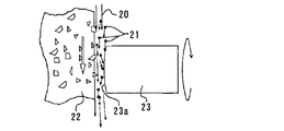
そこで、特許文献1のものは、光ファイバーコネクタ端面の加工であるが、粗加工から仕上げ加工までをカップ砥石を用いた研削手段による研削加工により所定形状に加工し、さらに、カップ砥石と端面との間に微少隙間を設け、この微少隙間に遊離砥粒をカップ砥石による連れ回り加工により研磨加工し、研削、研磨加工を連続一工程で加工処理している。この連れ回り加工は図5に示すように、加工液中20の遊離砥粒21が高速回転するカップ砥石22により加速され加工中のコネクタ23の端面23aに衝突し、カップ砥石が非接触状態で加工を行う。この非接触加工は、非常にワークに与えるダメージが少なく、適当な時間保持すれば、遊離砥粒21による非接触加工のみによって加工が行われ、面のきれいな端面加工が可能となる。また、特許文献2においては、棒状材の切断と端面研磨を円盤状の剛性体による遊離砥粒の連れ回り加工により行っている。また、特許文献3においては、タービンブレードのR部をタービンブレードより高硬度のセラミック円盤とR部との間に遊離砥粒を介在させている。但しこの場合は砥粒をタービンブレード側に押しつけているので、特許文献1,2の連れ回り加工とは異なる。
しかしながら、特許文献1のものはカップ砥石面に対し所定角のワーク面を押しつけて研削加工し、さらに一定隙間にして、遊離砥粒を供給するだけであり、単純な形状に限られる。また、特許文献2のものは、砥石の平面形状を転写するに留まり、平面しか加工できない。また、特許文献3のものは砥粒を押しつけるので、特許文献1,2のような良好な面は得られない。また、かかる遊離砥粒による連れ回り加工又は類似の加工は前述したレンズの金型のような、自由曲面加工への適用については示唆も開示もされていない。
However, the thing of patent document 1 only presses the workpiece surface of a predetermined angle with respect to a cup grindstone surface, grinds it, makes it a fixed clearance, and supplies a free abrasive grain, and is restricted to a simple shape. Moreover, the thing of
さらに、遊離砥粒は加工面と研削砥石との間に引き込む必要があるため、砥特許文献1のように、凸面形状や、また特許文献2のように平面形状のものでしか行えない。このため、かかる遊離砥粒による連れ回り加工又は類似の加工は前述したレンズの金型のような、凹面の加工には適用されていない。また、端面を上向きにして、遊離砥粒を凹面内に保持してもよいが、この場合は逆に砥粒の入れ替わりが安定せず、必ずしも均一な面を得られない。また、加工端面を上向きにすると、加工装置が大きく複雑になるという問題があった。さらに、遊離砥粒は研削砥石による加速により散逸し易く、加工部の周囲を汚すことになり、高精度の機械には好ましくない。
Furthermore, since it is necessary to draw loose abrasive grains between the processed surface and the grinding wheel, it can be performed only in a convex shape as in Patent Literature 1 or in a planar shape as in
本発明の課題は、前述した問題点に鑑みて、研削砥石による研削加工と、研削砥石と遊離砥粒との連れ回り加工による研磨を凹端面加工で行える凹端面加工方法及び装置を提供することである。さらに、遊離砥粒の補足が容易で精度も高く、また、遊離砥粒が散逸しにくい凹端面加工方法及び装置を提供することである。 In view of the above-described problems, an object of the present invention is to provide a concave end face processing method and apparatus capable of performing grinding processing by a grinding wheel and polishing by concave end face processing of the grinding wheel and loose abrasive grains by concave end face processing. It is. It is another object of the present invention to provide a method and apparatus for processing a concave end face that is easy to supplement loose abrasive grains and has high accuracy, and in which loose abrasive grains are difficult to dissipate.
本発明においては、回転軸先端にワークを固定し、砥石軸回りに回転する棒状の研削砥石を前記回転軸と同方向のZ軸方向、前記回転軸と直角方向のX軸方向、前記Z及びX軸と直角方向の回転軸B軸回りに移動させ、前記ワーク端面を所定の凹面形状に研削加工した後、前記研削砥石の前記所定の凹面形状の軌跡とは、逃げ方向に所定の間隔となるように再度移動させ、かつ、遊離砥粒含有磁性流体の研磨液を前記凹面形状に加工された前記ワーク端面と前記研削砥石の隙間に供給し前記遊離砥粒含有磁性流体の研磨液に前記研削砥石により高速加速力を付与して前記研削砥石の連れ回りによる研磨加工をし、前記ワーク端面に凹端面を形成する方法であって、前記凹端面の対角線方向に磁力を配置し、前記遊離砥粒含有磁性流体の研磨液を前記凹端面に補足しながら研磨加工する凹端面加工方法を提供することにより上記課題を解決した。 In the present invention, a workpiece is fixed to the tip of the rotating shaft, and a rod-shaped grinding wheel rotating around the grinding wheel axis is arranged in the same Z-axis direction as the rotating shaft, the X-axis direction perpendicular to the rotating shaft, the Z and After moving around the rotation axis B axis perpendicular to the X axis and grinding the workpiece end surface into a predetermined concave shape, the predetermined concave shape locus of the grinding wheel is a predetermined interval in the escape direction. And the polishing liquid of the free abrasive-containing magnetic fluid is supplied to the gap between the workpiece end surface processed into the concave shape and the grinding wheel to the polishing liquid of the free abrasive-containing magnetic fluid A method of forming a concave end surface on the workpiece end surface by applying a high-speed acceleration force by a grinding wheel to form a concave end surface on the workpiece end surface, and arranging a magnetic force in a diagonal direction of the concave end surface, Polishing fluid for magnetic fluid containing abrasive grains It has solved the above problems by providing a concave end surface processing method of polishing while trapped in the concave end face.
即ち、非球面レンズ金型、自由曲面レンズ金型の研削加工と面粗さの向上させる方法として、超精密加工機に搭載した砥石軸スピンドルで研削加工を行ない金型の端面の形状を仕上げる。次に、加工した金型の形状計測を行い、金型の形状誤差を求める。そして、研削加工面に対して砥石とワーク間の隙間が所定に値になるようなNCプログラムを作成する(形状誤差に応じて、送り速度を設定すればよい)。研削加工後、ワークの外周部、または、砥石の外周部に磁石、電磁石を配置する。これにより、遊離砥粒含有磁性流体を用いた研磨液をワーク表面に滞在させる。この状態で、砥石軸スピンドルを回転させ、遊離砥粒含有磁性流体の研磨液を砥石外周に連れ回りさせ、加工ワークと砥石間に流れる研磨液(遊離砥粒)の流れによりワーク表面の磨き加工を行なうのである。なお、研磨液は全て磁力により補足されるのではなく、後から供給される研磨液や重力、砥石回転による加速力により流れ落ちていくので遊離砥石は適宜入れ替わる。また、ノズルからの供給量、磁力の強弱により凹端面部での遊離砥粒含有磁性流体の研磨液の補足量を制御する。 That is, as a method for improving the grinding and surface roughness of an aspheric lens mold and a free-form lens mold, grinding is performed with a grindstone spindle mounted on an ultra-precision machining machine to finish the shape of the end face of the mold. Next, the shape of the machined mold is measured to determine the shape error of the mold. Then, an NC program is created such that the clearance between the grindstone and the workpiece has a predetermined value with respect to the ground surface (the feed speed may be set according to the shape error). After grinding, a magnet and an electromagnet are disposed on the outer periphery of the workpiece or the outer periphery of the grindstone. Thereby, the polishing liquid using the magnetic fluid containing free abrasive grains is allowed to stay on the workpiece surface. In this state, the grinding wheel spindle is rotated to rotate the polishing fluid of the free fluid containing the free abrasive grains around the periphery of the grinding wheel, and the workpiece surface is polished by the flow of polishing fluid (free abrasive grains) flowing between the workpiece and the grinding stone. Is done. The polishing liquid is not supplemented entirely by magnetic force, but flows away due to the polishing liquid supplied later, gravity, and acceleration force caused by the rotation of the grindstone, so that the free whetstone is appropriately replaced. Further, the amount of the polishing liquid supplemented with the loose abrasive-containing magnetic fluid at the concave end surface is controlled by the supply amount from the nozzle and the strength of the magnetic force.
かかる方法を実施する装置としては、請求項2に記載の発明において、先端にワークが固定される回転軸と、棒状の研削砥石と、棒状の研削砥石が回転自在に設けられる砥石軸と、前記砥石軸が載置され、相対的に前記回転軸と同方向のZ軸方向、前記回転軸と直角方向のX軸方向、前記Z及びX軸と直角方向の回転軸B軸回りに移動可能にされた工具取付部と、研削加工された凹端面との間が所定の隙間になるように再度研削砥石の軌跡を制御できる手段と、前記凹端面と棒状砥石との間に遊離砥粒含有磁性流体の研磨液を供給するノズルと、前記凹端面の対角線方向に磁力を発生する磁石又は電磁石と、を有する凹端面加工装置とすればよい。なお、棒状の研削砥石の加工先端部を円柱状とし、その角部で端面を加工するようにすれば、加工端面と角部との隙間を小さくして連れ回り加工ができ、その他の部分は隙間が充分大きくなるので遊離砥粒の影響が少なく。精度のよい研磨ができる。
As an apparatus for carrying out such a method, in the invention according to
本発明によれば、磁性流体の遊離砥粒を凹端面の対角線方向に設けた磁力により凹端面に保持するようにしたので、レンズ等の金型の自由曲面や非球面、球面等の凹端面加工において、研削砥石による研削加工と、研削砥石と遊離砥粒との連れ回り加工による研磨加工方法及び装置を提供するものとなった。連れ回り加工による研磨ができるので高精度の加工ができる。また、磁力により遊離砥粒の補足ができるので、遊離砥粒含有磁性流体の研磨液が散逸しにくいものとなった。さらには、金型の形状要求精度が高く、深い形状や複雑な形状になった非球面、自由曲面形状の光学部品の金型に対しても、砥石、砥石軸スピンドルをそのまま用いて研磨加工を行なうことが可能となり、加工面の面粗さの改善を図ることができる。また、研磨加工に用いた砥石は、遊離砥粒含有磁性流体の研磨液との作用により、ドレス効果がえられ、砥石の切れ味の回復を図る効果がえられるものとなった。 According to the present invention, the loose abrasive grains of the magnetic fluid are held on the concave end surface by the magnetic force provided in the diagonal direction of the concave end surface, so that the free curved surface of the mold such as a lens or the concave end surface such as an aspherical surface or a spherical surface In the processing, the present invention provides a polishing method and apparatus by grinding with a grinding wheel and accompanying processing of the grinding wheel and loose abrasive grains. High-precision processing is possible because polishing can be performed by follow-up processing. Further, since the free abrasive grains can be supplemented by the magnetic force, the polishing liquid of the free abrasive-containing magnetic fluid is difficult to dissipate. In addition, the required accuracy of the mold shape is high, and even for aspherical and free-form optical component molds with deep and complex shapes, grinding using the grindstone and grindstone spindle as it is Therefore, the surface roughness of the processed surface can be improved. In addition, the grindstone used in the polishing process has a dress effect due to the action of the free abrasive-containing magnetic fluid with the polishing liquid, and an effect of recovering the sharpness of the grindstone.
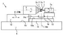
本発明の実施の形態について図面を参照して説明する。図1は本発明の実施の形態を示す凹端面加工装置の平面図、図2は同側面図、図3はワークと研削砥石との関係を示し、磁界を上下方向に配置した場合の拡大断面平面図、図4は磁界を横(加工)方向に配置した場合の側面図である。図1、2において、本凹端面加工装置1は、基台6上にZ軸4方向に移動可能なワークテーブル12とZ軸と直角(X軸5)方向に移動可能な工具テーブル13が載置され、ワークテーブル12上にZ軸と同方向の回転軸3が設けられている。回転軸3の端部3aにワーク2が取付けられるようにされ、ワークは回転軸回りに回転可能にされている。工具テーブル13の上にはテーブル面13aに垂直に旋回軸であるB軸14b回りに旋回可能にされた旋回ステージ14、さらに、旋回ステージ上14aに工具取付部15が設けられ、工具取付部には砥石軸7a回りに軸回転可能に棒状の研削砥石7が取付けられている。研削砥石7は円柱状に形成され、円柱状外面の角部7bをワーク端面2aに対して移動させてワーク端面を加工する加工先端部としている。研削砥石7の軸心7aは基台面6aに対して平行にされ、回転軸3に対して傾けて取り付けられ、また高さは回転軸3と同じにされている。回転軸3やワークテーブル12,工具テーブル13、旋回ステージ14、砥石軸7a等の送りには流体軸受や、高精度転がり軸受が使用されており、さらにX軸5、Z軸4、旋回軸14bはサーボモータを使用したNC制御により高精度に制御され、超精密非球面加工が可能にされている。なお、回転軸3、砥石軸7aもNC制御することが好ましい。また、上下方向にNC制御できるようにしてもよいが、少なくともX、Z、B軸が制御されることが必要である。なお、図1に点線で示す符号8は計測用のプローブ接触式計測器であり、加工工程中に必要に応じて都度取付けられワーク端面形状を測定する。
Embodiments of the present invention will be described with reference to the drawings. FIG. 1 is a plan view of a concave end surface processing apparatus showing an embodiment of the present invention, FIG. 2 is a side view of the same, FIG. 3 shows the relationship between a workpiece and a grinding wheel, and an enlarged cross section when a magnetic field is arranged vertically. FIG. 4 is a plan view and FIG. 4 is a side view when the magnetic field is arranged in the lateral (processing) direction. 1 and 2, the concave end surface processing apparatus 1 has a work table 12 movable in the Z-
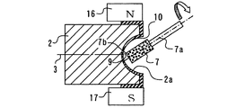
特に、本発明においては、研磨工程時には、図3に示すように、ワーク3の凹端面2aと研削砥石7の角部7bとの隙間9に遊離砥粒含有磁性流体の研磨液10が供給可能にノズル11が設けられる。さらに、凹端面の上下に対角線方向になるようにそれぞれ電磁石16,17が設けられ、上側をN極、下側をS極とし、磁界が形成される。研磨液は電磁石は図4に示すように横方向に配置してもよい。この電磁石の磁界により、遊離砥粒含有磁性流体の研磨液10が補足される。ワーク端面の下方には受皿18が設けられ下方に落下する遊離砥粒含有磁性流体の研磨液を受け、図示しない研磨液タンクへ戻すようにされている。ワーク端面2aの研削加工は、回転軸3、Z軸4、X軸5、B軸14b、砥石軸7aを相対移動させ凹端面研削を行うようにされている。また、研磨加工時においては、研削加工された凹端面2aと角部7bとの間(凹端面の逃げ方向)が所定の隙間9、例えば数nm(ナノメータ)〜数μm(ミクロンメータ)の隙間を保ちながら再度研削砥石の角部7bの軌跡を制御できるようにされている。
In particular, in the present invention, during the polishing process, as shown in FIG. 3, the polishing
かかる凹端面加工装置において、まず、回転軸3の端面3aに加工ワーク2を取付け、棒状砥石7を用いて、角部7bにより、ワーク端面の凹面の研削加工を行なう。研削加工ワーク2は、機械上に搭載された形状測定装置8を用いて形状測定を行なう。研削加工で仕上げた軌跡に対して、棒状砥石7の角部7bとワーク2の凹端面2aの隙間9が所定の値になるように、研磨加工用のNC制御させる。一方、ワークの外周に電磁石16,17を設置し、ノズル11から温度調整された遊離砥粒含有磁性流体の研磨液10を供給する。電磁石16,17に通電した状態で遊離砥粒含有磁性流体の研磨液10を供給すると、ワークの表面に充分な量の遊離砥粒含有磁性流体の研磨液が滞在する。砥石軸7aスピンドルを回転させ、砥石7の角部7bとワーク2の凹端面2aとの間が所定の隙間になるように、NCプログラムにて軸移動を行なう。これにより、棒状砥石の回転につれ回りして遊離砥粒含有磁性流体の研磨液10に回転が生じ、遊離砥粒がワーク凹端面2aに当る箇所で、研磨の効果が得られ、加工面2aの面粗さが改善する。なお、棒状砥石7の回転速度、遊離砥粒の大きさ等は、前述した研削砥石と遊離砥粒による連れ回り研磨が可能な速度(例えば、数千〜数万回転)、大きさ(0.1〜0.5μm)、砥粒材質(超微粒子シリカ)等適宜選択するのはいうまでもない。また、実施の形態では先端に円柱状外面の角部を有する棒状の砥石について説明したが、棒状砥石は円筒状、円柱状、外形が異なる円筒又は円柱状の砥石が軸方向に連接された段付状等の種々の形状が可能である。さらに、成形砥石やその他の種々の砥石による加工方法や装置に適用できることはいうまでもない。
In such a concave end surface processing apparatus, first, the
1 凹端面加工装置
2 ワーク 2a ワーク端面(凹端面)
3 回転軸 3a 回転軸先端
4 Z軸
5 X軸
7 棒状の研削砥石 7a 砥石軸
9 隙間
10 遊離砥粒含有磁性流体の研磨液
11 ノズル
14b B軸
15 工具取付部
16、17 磁石又は電磁石
DESCRIPTION OF SYMBOLS 1 Concave end
DESCRIPTION OF
Claims (2)
A rotating shaft to which a workpiece is fixed at the tip, a rod-shaped grinding wheel, a grindstone shaft on which a rod-shaped grinding wheel is rotatably provided, and the grindstone shaft are mounted and relatively Z in the same direction as the rotating shaft A predetermined distance is provided between the tool mounting portion that is movable in the axial direction, the X-axis direction perpendicular to the rotation axis, the rotation axis B-axis perpendicular to the Z and X axes, and the ground end surface that has been ground. Means capable of controlling the trajectory of the grinding wheel again so as to form a gap of the following, a nozzle for supplying a polishing liquid of magnetic fluid containing free abrasive grains between the concave end surface and the rod-shaped grinding wheel, and a magnetic force in the diagonal direction of the concave end surface A concave end surface processing apparatus comprising: a magnet or an electromagnet that generates
Priority Applications (1)
| Application Number | Priority Date | Filing Date | Title |
|---|---|---|---|
| JP2003336796A JP4458235B2 (en) | 2003-09-29 | 2003-09-29 | Concave end machining method and apparatus |
Applications Claiming Priority (1)
| Application Number | Priority Date | Filing Date | Title |
|---|---|---|---|
| JP2003336796A JP4458235B2 (en) | 2003-09-29 | 2003-09-29 | Concave end machining method and apparatus |
Publications (2)
| Publication Number | Publication Date |
|---|---|
| JP2005103669A true JP2005103669A (en) | 2005-04-21 |
| JP4458235B2 JP4458235B2 (en) | 2010-04-28 |
Family
ID=34532793
Family Applications (1)
| Application Number | Title | Priority Date | Filing Date |
|---|---|---|---|
| JP2003336796A Expired - Fee Related JP4458235B2 (en) | 2003-09-29 | 2003-09-29 | Concave end machining method and apparatus |
Country Status (1)
| Country | Link |
|---|---|
| JP (1) | JP4458235B2 (en) |
Cited By (8)
| Publication number | Priority date | Publication date | Assignee | Title |
|---|---|---|---|---|
| JP2008110435A (en) * | 2006-10-31 | 2008-05-15 | Fanuc Ltd | Machine tool having contact detection mechanism between tool and workpiece |
| WO2009119117A1 (en) | 2008-03-27 | 2009-10-01 | パナソニック株式会社 | Measurement device, measurement system, and concentration measurement method |
| CN102161168A (en) * | 2011-01-19 | 2011-08-24 | 湖南大学 | Small-caliber aspherical composite precise processing machine tool |
| CN102161169A (en) * | 2011-01-19 | 2011-08-24 | 湖南大学 | Small-caliber aspherical composite precise processing method |
| CN102320023A (en) * | 2011-10-13 | 2012-01-18 | 南京航空航天大学 | High-speed tool constraint abrasive material piece surface controllable accurate polishing processing technology |
| CN102990500A (en) * | 2012-12-26 | 2013-03-27 | 哈尔滨工业大学 | Magnetorheological polishing device with vertical shaft and tilting shaft with rotary table hung upside down |
| KR20190021886A (en) * | 2017-08-24 | 2019-03-06 | 인하대학교 산학협력단 | Apparatus for grinding |
| WO2024045493A1 (en) * | 2022-08-30 | 2024-03-07 | 大连理工大学 | Shape-controlled flexible polishing method for microarray mold |
Families Citing this family (1)
| Publication number | Priority date | Publication date | Assignee | Title |
|---|---|---|---|---|
| CN109396966B (en) * | 2018-11-26 | 2020-12-15 | 南京航空航天大学 | A method for machining a concave spherical cap or a concave spherical torus with a multi-magnet arrangement annular magnetorheological polishing tool |
Citations (7)
| Publication number | Priority date | Publication date | Assignee | Title |
|---|---|---|---|---|
| JPS61244457A (en) * | 1985-04-18 | 1986-10-30 | アマダ エンジニアリング アンド サ−ビス カンパニ− インコ−ポレ−テツド | Grinder using magnetic fluid |
| JPH05314472A (en) * | 1992-05-12 | 1993-11-26 | Furukawa Electric Co Ltd:The | Manufacture of substrate for magnetic disk |
| JPH08168960A (en) * | 1994-12-14 | 1996-07-02 | Sharp Corp | Grinding device |
| JPH09248750A (en) * | 1996-03-12 | 1997-09-22 | Nippon Telegr & Teleph Corp <Ntt> | Optical fiber connector end face processing method and device |
| JP2000210855A (en) * | 1999-01-21 | 2000-08-02 | Olympus Optical Co Ltd | Ultra precision polishing method for molding die |
| JP2001310252A (en) * | 2000-02-21 | 2001-11-06 | Olympus Optical Co Ltd | Method and device for grinding and polishing work piece |
| JP2002205253A (en) * | 2001-01-11 | 2002-07-23 | Olympus Optical Co Ltd | Polishing method for optical member |
-
2003
- 2003-09-29 JP JP2003336796A patent/JP4458235B2/en not_active Expired - Fee Related
Patent Citations (7)
| Publication number | Priority date | Publication date | Assignee | Title |
|---|---|---|---|---|
| JPS61244457A (en) * | 1985-04-18 | 1986-10-30 | アマダ エンジニアリング アンド サ−ビス カンパニ− インコ−ポレ−テツド | Grinder using magnetic fluid |
| JPH05314472A (en) * | 1992-05-12 | 1993-11-26 | Furukawa Electric Co Ltd:The | Manufacture of substrate for magnetic disk |
| JPH08168960A (en) * | 1994-12-14 | 1996-07-02 | Sharp Corp | Grinding device |
| JPH09248750A (en) * | 1996-03-12 | 1997-09-22 | Nippon Telegr & Teleph Corp <Ntt> | Optical fiber connector end face processing method and device |
| JP2000210855A (en) * | 1999-01-21 | 2000-08-02 | Olympus Optical Co Ltd | Ultra precision polishing method for molding die |
| JP2001310252A (en) * | 2000-02-21 | 2001-11-06 | Olympus Optical Co Ltd | Method and device for grinding and polishing work piece |
| JP2002205253A (en) * | 2001-01-11 | 2002-07-23 | Olympus Optical Co Ltd | Polishing method for optical member |
Cited By (11)
| Publication number | Priority date | Publication date | Assignee | Title |
|---|---|---|---|---|
| JP2008110435A (en) * | 2006-10-31 | 2008-05-15 | Fanuc Ltd | Machine tool having contact detection mechanism between tool and workpiece |
| US7905691B2 (en) | 2006-10-31 | 2011-03-15 | Fanu Ltd | Machine tool having function of detecting contact between tool and workpiece |
| WO2009119117A1 (en) | 2008-03-27 | 2009-10-01 | パナソニック株式会社 | Measurement device, measurement system, and concentration measurement method |
| CN102161168A (en) * | 2011-01-19 | 2011-08-24 | 湖南大学 | Small-caliber aspherical composite precise processing machine tool |
| CN102161169A (en) * | 2011-01-19 | 2011-08-24 | 湖南大学 | Small-caliber aspherical composite precise processing method |
| CN102161168B (en) * | 2011-01-19 | 2012-07-18 | 湖南大学 | Small-caliber aspherical composite precise processing machine tool |
| CN102320023A (en) * | 2011-10-13 | 2012-01-18 | 南京航空航天大学 | High-speed tool constraint abrasive material piece surface controllable accurate polishing processing technology |
| CN102990500A (en) * | 2012-12-26 | 2013-03-27 | 哈尔滨工业大学 | Magnetorheological polishing device with vertical shaft and tilting shaft with rotary table hung upside down |
| KR20190021886A (en) * | 2017-08-24 | 2019-03-06 | 인하대학교 산학협력단 | Apparatus for grinding |
| KR101970402B1 (en) * | 2017-08-24 | 2019-04-18 | 인하대학교 산학협력단 | Apparatus for grinding |
| WO2024045493A1 (en) * | 2022-08-30 | 2024-03-07 | 大连理工大学 | Shape-controlled flexible polishing method for microarray mold |
Also Published As
| Publication number | Publication date |
|---|---|
| JP4458235B2 (en) | 2010-04-28 |
Similar Documents
| Publication | Publication Date | Title |
|---|---|---|
| US4760672A (en) | Simultaneously grinding and polishing preforms for optical lenses | |
| JPH0516070A (en) | Diamond grinding wheel, its truing method, truing device, and ground-finished magnetic head | |
| JP3363587B2 (en) | Method and apparatus for processing brittle material | |
| AU2005271466B2 (en) | Raster cutting technology for ophthalmic lenses | |
| CN101486167A (en) | Device and method to trim a processing disk using a rotating processing tool and tool device with such a device | |
| CN108311960B (en) | Polishing device and method for optical free-form surface | |
| JP4458235B2 (en) | Concave end machining method and apparatus | |
| CN1174110A (en) | Spherical part track forming processing method and device | |
| JP4668872B2 (en) | Grinding method and grinding apparatus | |
| JP5300939B2 (en) | Machining method using finishing tools | |
| JP2002263995A (en) | Method and apparatus for grinding spherical surface | |
| Shiou et al. | Ultra precision surface finishing processes | |
| JP2005103668A (en) | Free-form surface machining method and device | |
| CN208034278U (en) | A kind of burnishing device of freeform optics surface | |
| JP2017124460A (en) | Method and apparatus for continuously processing non-spherical shape of workpiece by cup shaped grind stone | |
| JP2006320970A (en) | Machining device | |
| JP2002001657A (en) | ELID grinding machine for fine shape processing | |
| JP2003205459A (en) | Polishing apparatus and method | |
| JP4261493B2 (en) | Dressing device, grinding device, dressing method, and numerical control program | |
| CN105666327B (en) | Method, device and machine tool for dressing complex section superabrasive grinding wheel by using roller | |
| JP2006055961A (en) | Method and apparatus for machining axially symmetric aspheric surface by surface grinding machine | |
| Suzuki et al. | Precision machining and measurement of micro aspheric molds | |
| JP2006334748A (en) | Internal surface grinding wheel, grinding device and forming device | |
| JP2003260646A (en) | Grinding method of nonaxisymmetric and aspheric surface, and its device | |
| JP2009095973A (en) | Grinding wheel molding device and method |
Legal Events
| Date | Code | Title | Description |
|---|---|---|---|
| A621 | Written request for application examination |
Free format text: JAPANESE INTERMEDIATE CODE: A621 Effective date: 20060927 |
|
| A977 | Report on retrieval |
Free format text: JAPANESE INTERMEDIATE CODE: A971007 Effective date: 20080526 |
|
| A131 | Notification of reasons for refusal |
Free format text: JAPANESE INTERMEDIATE CODE: A131 Effective date: 20090908 |
|
| A521 | Written amendment |
Free format text: JAPANESE INTERMEDIATE CODE: A523 Effective date: 20091026 |
|
| TRDD | Decision of grant or rejection written | ||
| A01 | Written decision to grant a patent or to grant a registration (utility model) |
Free format text: JAPANESE INTERMEDIATE CODE: A01 Effective date: 20100119 |
|
| A01 | Written decision to grant a patent or to grant a registration (utility model) |
Free format text: JAPANESE INTERMEDIATE CODE: A01 |
|
| A61 | First payment of annual fees (during grant procedure) |
Free format text: JAPANESE INTERMEDIATE CODE: A61 Effective date: 20100202 |
|
| R150 | Certificate of patent or registration of utility model |
Free format text: JAPANESE INTERMEDIATE CODE: R150 |
|
| FPAY | Renewal fee payment (event date is renewal date of database) |
Free format text: PAYMENT UNTIL: 20130219 Year of fee payment: 3 |
|
| FPAY | Renewal fee payment (event date is renewal date of database) |
Free format text: PAYMENT UNTIL: 20130219 Year of fee payment: 3 |
|
| FPAY | Renewal fee payment (event date is renewal date of database) |
Free format text: PAYMENT UNTIL: 20140219 Year of fee payment: 4 |
|
| LAPS | Cancellation because of no payment of annual fees |