JP2005081663A - Resin tubes and fuel piping tubes - Google Patents
Resin tubes and fuel piping tubes Download PDFInfo
- Publication number
- JP2005081663A JP2005081663A JP2003315332A JP2003315332A JP2005081663A JP 2005081663 A JP2005081663 A JP 2005081663A JP 2003315332 A JP2003315332 A JP 2003315332A JP 2003315332 A JP2003315332 A JP 2003315332A JP 2005081663 A JP2005081663 A JP 2005081663A
- Authority
- JP
- Japan
- Prior art keywords
- layer
- resin
- copolymer
- fuel
- resin tube
- Prior art date
- Legal status (The legal status is an assumption and is not a legal conclusion. Google has not performed a legal analysis and makes no representation as to the accuracy of the status listed.)
- Pending
Links
Images
Classifications
-
- B—PERFORMING OPERATIONS; TRANSPORTING
- B32—LAYERED PRODUCTS
- B32B—LAYERED PRODUCTS, i.e. PRODUCTS BUILT-UP OF STRATA OF FLAT OR NON-FLAT, e.g. CELLULAR OR HONEYCOMB, FORM
- B32B1/00—Layered products having a non-planar shape
- B32B1/08—Tubular products
-
- B—PERFORMING OPERATIONS; TRANSPORTING
- B32—LAYERED PRODUCTS
- B32B—LAYERED PRODUCTS, i.e. PRODUCTS BUILT-UP OF STRATA OF FLAT OR NON-FLAT, e.g. CELLULAR OR HONEYCOMB, FORM
- B32B27/00—Layered products comprising a layer of synthetic resin
- B32B27/36—Layered products comprising a layer of synthetic resin comprising polyesters
-
- F—MECHANICAL ENGINEERING; LIGHTING; HEATING; WEAPONS; BLASTING
- F16—ENGINEERING ELEMENTS AND UNITS; GENERAL MEASURES FOR PRODUCING AND MAINTAINING EFFECTIVE FUNCTIONING OF MACHINES OR INSTALLATIONS; THERMAL INSULATION IN GENERAL
- F16L—PIPES; JOINTS OR FITTINGS FOR PIPES; SUPPORTS FOR PIPES, CABLES OR PROTECTIVE TUBING; MEANS FOR THERMAL INSULATION IN GENERAL
- F16L11/00—Hoses, i.e. flexible pipes
- F16L11/04—Hoses, i.e. flexible pipes made of rubber or flexible plastics
- F16L11/045—Hoses, i.e. flexible pipes made of rubber or flexible plastics with four or more layers without reinforcement
-
- F—MECHANICAL ENGINEERING; LIGHTING; HEATING; WEAPONS; BLASTING
- F16—ENGINEERING ELEMENTS AND UNITS; GENERAL MEASURES FOR PRODUCING AND MAINTAINING EFFECTIVE FUNCTIONING OF MACHINES OR INSTALLATIONS; THERMAL INSULATION IN GENERAL
- F16L—PIPES; JOINTS OR FITTINGS FOR PIPES; SUPPORTS FOR PIPES, CABLES OR PROTECTIVE TUBING; MEANS FOR THERMAL INSULATION IN GENERAL
- F16L11/00—Hoses, i.e. flexible pipes
- F16L11/04—Hoses, i.e. flexible pipes made of rubber or flexible plastics
- F16L11/11—Hoses, i.e. flexible pipes made of rubber or flexible plastics with corrugated wall
- F16L11/118—Hoses, i.e. flexible pipes made of rubber or flexible plastics with corrugated wall having arrangements for particular purposes, e.g. electrically conducting
- F16L11/1185—Hoses, i.e. flexible pipes made of rubber or flexible plastics with corrugated wall having arrangements for particular purposes, e.g. electrically conducting electrically conducting
-
- F—MECHANICAL ENGINEERING; LIGHTING; HEATING; WEAPONS; BLASTING
- F16—ENGINEERING ELEMENTS AND UNITS; GENERAL MEASURES FOR PRODUCING AND MAINTAINING EFFECTIVE FUNCTIONING OF MACHINES OR INSTALLATIONS; THERMAL INSULATION IN GENERAL
- F16L—PIPES; JOINTS OR FITTINGS FOR PIPES; SUPPORTS FOR PIPES, CABLES OR PROTECTIVE TUBING; MEANS FOR THERMAL INSULATION IN GENERAL
- F16L11/00—Hoses, i.e. flexible pipes
- F16L11/04—Hoses, i.e. flexible pipes made of rubber or flexible plastics
- F16L11/12—Hoses, i.e. flexible pipes made of rubber or flexible plastics with arrangements for particular purposes, e.g. specially profiled, with protecting layer, heated, electrically conducting
- F16L11/127—Hoses, i.e. flexible pipes made of rubber or flexible plastics with arrangements for particular purposes, e.g. specially profiled, with protecting layer, heated, electrically conducting electrically conducting
-
- B—PERFORMING OPERATIONS; TRANSPORTING
- B32—LAYERED PRODUCTS
- B32B—LAYERED PRODUCTS, i.e. PRODUCTS BUILT-UP OF STRATA OF FLAT OR NON-FLAT, e.g. CELLULAR OR HONEYCOMB, FORM
- B32B2250/00—Layers arrangement
- B32B2250/24—All layers being polymeric
-
- B—PERFORMING OPERATIONS; TRANSPORTING
- B32—LAYERED PRODUCTS
- B32B—LAYERED PRODUCTS, i.e. PRODUCTS BUILT-UP OF STRATA OF FLAT OR NON-FLAT, e.g. CELLULAR OR HONEYCOMB, FORM
- B32B2250/00—Layers arrangement
- B32B2250/40—Symmetrical or sandwich layers, e.g. ABA, ABCBA, ABCCBA
-
- B—PERFORMING OPERATIONS; TRANSPORTING
- B32—LAYERED PRODUCTS
- B32B—LAYERED PRODUCTS, i.e. PRODUCTS BUILT-UP OF STRATA OF FLAT OR NON-FLAT, e.g. CELLULAR OR HONEYCOMB, FORM
- B32B2262/00—Composition or structural features of fibres which form a fibrous or filamentary layer or are present as additives
- B32B2262/02—Synthetic macromolecular fibres
- B32B2262/0276—Polyester fibres
- B32B2262/0284—Polyethylene terephthalate [PET] or polybutylene terephthalate [PBT]
-
- F—MECHANICAL ENGINEERING; LIGHTING; HEATING; WEAPONS; BLASTING
- F16—ENGINEERING ELEMENTS AND UNITS; GENERAL MEASURES FOR PRODUCING AND MAINTAINING EFFECTIVE FUNCTIONING OF MACHINES OR INSTALLATIONS; THERMAL INSULATION IN GENERAL
- F16L—PIPES; JOINTS OR FITTINGS FOR PIPES; SUPPORTS FOR PIPES, CABLES OR PROTECTIVE TUBING; MEANS FOR THERMAL INSULATION IN GENERAL
- F16L11/00—Hoses, i.e. flexible pipes
- F16L11/04—Hoses, i.e. flexible pipes made of rubber or flexible plastics
- F16L2011/047—Hoses, i.e. flexible pipes made of rubber or flexible plastics with a diffusion barrier layer
-
- Y—GENERAL TAGGING OF NEW TECHNOLOGICAL DEVELOPMENTS; GENERAL TAGGING OF CROSS-SECTIONAL TECHNOLOGIES SPANNING OVER SEVERAL SECTIONS OF THE IPC; TECHNICAL SUBJECTS COVERED BY FORMER USPC CROSS-REFERENCE ART COLLECTIONS [XRACs] AND DIGESTS
- Y10—TECHNICAL SUBJECTS COVERED BY FORMER USPC
- Y10T—TECHNICAL SUBJECTS COVERED BY FORMER US CLASSIFICATION
- Y10T428/00—Stock material or miscellaneous articles
- Y10T428/13—Hollow or container type article [e.g., tube, vase, etc.]
- Y10T428/1352—Polymer or resin containing [i.e., natural or synthetic]
- Y10T428/139—Open-ended, self-supporting conduit, cylinder, or tube-type article
- Y10T428/1393—Multilayer [continuous layer]
Landscapes
- Engineering & Computer Science (AREA)
- General Engineering & Computer Science (AREA)
- Mechanical Engineering (AREA)
- Rigid Pipes And Flexible Pipes (AREA)
- Laminated Bodies (AREA)
Abstract
【課題】通常のガソリンの他に含アルコール燃料に対しても優れた耐燃料透過性を有し、燃料遮断層と保護層との接着性が十分高く、端材等の再利用が容易で、安価な材料の構成で樹脂製チューブ及び燃料系配管用チューブを提供することにある。
【解決手段】PBN含有層、PBNとPTMGとから成る共重合体含有層、PBT含有層及びPBTセグメントを含む他の共重合体含有層の一方又は双方、を有する多層構造の管状樹脂層を備え、PBN含有層の内側及び外側には、PBNとPTMGとから成る共重合体含有層が配設されて成る樹脂製チューブ。
上述の如き樹脂製チューブから成る燃料系配管用チューブ。
【選択図】なし
[PROBLEMS] To have excellent fuel permeation resistance for alcohol-containing fuel in addition to normal gasoline, sufficiently high adhesion between a fuel cutoff layer and a protective layer, and easy reuse of scraps, An object of the present invention is to provide a resin tube and a fuel system tube with an inexpensive material structure.
A multi-layered tubular resin layer having a PBN-containing layer, a copolymer-containing layer made of PBN and PTMG, one or both of a PBT-containing layer and another copolymer-containing layer containing a PBT segment is provided. A resin tube in which a copolymer-containing layer made of PBN and PTMG is disposed inside and outside the PBN-containing layer.
A fuel piping tube comprising a resin tube as described above.
[Selection figure] None
Description
本発明は、樹脂製チューブ及び燃料系配管用チューブに係り、更に詳細には、軽量性及び防錆性に優れると共に、高温雰囲気下での優れた耐層間剥離性、高い燃料バリアー性(耐燃料透過性)及び耐燃料油性を有し、且つ再利用も容易な、ポリブチレンナフタレート樹脂を燃料遮断層として具備した樹脂製チューブ及び燃料系配管用チューブ、特に自動車への適用に好適な燃料系配管用チューブに関する。 The present invention relates to a resin tube and a fuel piping tube. More specifically, the present invention is excellent in lightness and rust prevention, and has excellent delamination resistance and high fuel barrier property (fuel resistance) in a high temperature atmosphere. Permeability) and fuel oil resistance, and easy to reuse Resin tube and fuel system piping tube with polybutylene naphthalate resin as fuel barrier layer, especially fuel system suitable for automobile application It relates to a tube for piping.
従来から、フィードチューブ、リターンチューブ、エバポホース及びフィラーホース等の自動車の燃料系配管には、金属製、ゴム製、樹脂製又はこれらのうちの2種乃至3種を組み合わせた複合構造のものが使用されている。特に最近では、これまで主流であった金属製のものに替わって、錆の発生が無いことや軽量化が可能であること、更にコスト的に有利であることなどから、樹脂製のものに切り替わりつつある。
しかしながら、一般に樹脂製のものは、金属製のものに比べて、耐燃料透過性に劣るという欠点があり、今後益々厳しくなると予想される燃料蒸散規制に対しては、いっそう透過を抑えることが要求されている。
樹脂製配管等の耐燃料透過性を向上させることを目的とした開発は種々報告されてはいるものの、含アルコール燃料に対しても耐燃料透過性に優れ、しかも材料及び製造の面で現実的で安価な構成は報告されていない。
Conventionally, automobile fuel system piping such as feed tubes, return tubes, evaporation hoses and filler hoses are made of metal, rubber, resin, or a composite structure in which two to three of these are combined. Has been. Especially recently, instead of the metal mainstream so far, it is switched to the resin one because there is no rust generation, it is possible to reduce the weight, and it is more cost effective. It's getting on.
However, in general, resin-made ones have the disadvantage that they are inferior in fuel permeation resistance compared to metal-made ones, and it is required to further suppress permeation for fuel evaporation regulations that are expected to become increasingly severe in the future. Has been.
Although various developments aimed at improving the fuel permeation resistance of resin pipes have been reported, it is excellent in fuel permeation resistance even for alcohol-containing fuels, and is realistic in terms of materials and production. No inexpensive configuration has been reported.
例えば、内層(バリア層)にフッ素樹脂(エチレン・テトラフルオロエチレン共重合体)を用い、中間層に接着層を設置し、外層にポリアミド12を用いた構成が提案されている(例えば、特許文献1参照。)。
また、バリア層にポリフェニレンサルファイド(PPS)を適用した構成が提案されている(例えば、特許文献2及び3参照。)。
更に、接着層を設けずプラズマ等の表面処理によってバリア層(内層)と保護層(外層)を接着させる方法が提案されている(例えば、特許文献4及び5参照。)。
Further, a configuration in which polyphenylene sulfide (PPS) is applied to the barrier layer has been proposed (see, for example, Patent Documents 2 and 3).
Further, a method has been proposed in which a barrier layer (inner layer) and a protective layer (outer layer) are adhered by surface treatment such as plasma without providing an adhesive layer (see, for example, Patent Documents 4 and 5).
しかしながら、特許文献1に示される上述した従来技術では、(1)フッ素樹脂自体が高価である、(2)更にフッ素樹脂と外層であるポリアミド12とを接着するために用いる接着層が高価である、という問題点があった。これに対し、材料コストを抑制すべく、フッ素樹脂を含む層の薄肉化が検討されたが、十分な耐圧を確保することができないため、十分な薄肉化は困難となりコスト削減は達成され得ない。
一方、更に強い接着性を得るため、内層であるフッ素樹脂を押出し成形して、その表面にナトリウム−アンモニア錯体を含む化学処理液を適用して、活性基を導入する表面処理などをする場合には、製造工程が極めて複雑になると共に、更にコストを上昇させてしまう。
However, in the above-described prior art disclosed in
On the other hand, in order to obtain stronger adhesiveness, when extruding a fluororesin as the inner layer and applying a chemical treatment liquid containing sodium-ammonia complex to its surface, surface treatment to introduce active groups, etc. However, the manufacturing process becomes extremely complicated and the cost is further increased.
また、特許文献2又は3に示される上述した従来技術では、(1)接着層を設ける必要がある、(2)PPS層及び接着層が高価である、という問題点があり、上述のフッ素樹脂と同様に現実的なコストレベルとなる組み合わせとはなり難い。
これらの問題は、いずれの場合においてもバリア層(内層)と保護層(外層)を異種の材料にしたことが原因である。即ち、異種材料を組み合わせた場合においては、そのままでは強い接着性が得られないため、接着層が必要となり、且つ接着層自体が高価であることから配管(積層チューブ)が必然的に高価になるという欠点がある。
Moreover, in the above-described conventional technology disclosed in Patent Document 2 or 3, there is a problem that (1) it is necessary to provide an adhesive layer, and (2) the PPS layer and the adhesive layer are expensive. It is difficult to achieve a combination that achieves a realistic cost level.
These problems are caused by using different materials for the barrier layer (inner layer) and the protective layer (outer layer) in any case. That is, when different materials are combined, strong adhesiveness cannot be obtained as it is, so that an adhesive layer is necessary, and the adhesive layer itself is expensive, so piping (laminated tube) is necessarily expensive. There is a drawback.
更に、特許文献4又は5に示される上述した従来技術では、製造工程が煩雑になり、上記問題の根本的な解決策とはなり難い。また、このような異種材料による組み合わせでは、工程内で端材を再利用することが極めて困難であり、この点も大きな問題となっている。 Furthermore, in the above-described prior art disclosed in Patent Document 4 or 5, the manufacturing process becomes complicated, and it is difficult to be a fundamental solution to the above problem. In addition, in such a combination of different materials, it is extremely difficult to reuse the end material in the process, which is also a big problem.
本発明は、このような従来技術の有する課題に鑑みてなされたものであり、その目的とするところは、通常のガソリンの他に含アルコール燃料に対しても優れた耐燃料透過性を有し、バリア層(燃料遮断層)と保護層(燃料遮断層以外の層)との接着性が十分高く、端材等の再利用が容易であると共に安価な材料の構成で樹脂製チューブ及び燃料系配管用チューブを提供することにある。 The present invention has been made in view of such problems of the prior art, and the object of the present invention is to have excellent fuel permeation resistance for alcohol-containing fuels in addition to ordinary gasoline. Adhesiveness between the barrier layer (fuel barrier layer) and the protective layer (layers other than the fuel barrier layer) is sufficiently high, and it is easy to recycle offcuts, etc. It is to provide a tube for piping.
本発明者らは、上記目的を達成すべく鋭意検討を重ねた結果、所定のポリエステル樹脂を用いた多層構造とすることなどにより、上記目的が達成できることを見出し、本発明を完成するに至った。 As a result of intensive studies to achieve the above object, the present inventors have found that the above object can be achieved by making a multilayer structure using a predetermined polyester resin, and have completed the present invention. .
即ち、本発明の樹脂製チューブは、ポリブチレンナフタレート(PBN)含有層、ポリブチレンナフタレート(PBN)とポリテトラメチレングリコール(PTMG)とから成る共重合体含有層、ポリブチレンテレフタレート(PBT)含有層及び/又はポリブチレンテレフタレート(PBT)セグメントを含む他の共重合体含有層、を有する多層構造の管状樹脂層を備える樹脂製チューブである。上記ポリブチレンナフタレート(PBN)含有層の内側及び外側には、上記ポリブチレンナフタレート(PBN)とポリテトラメチレングリコール(PTMG)とから成る共重合体含有層が配設されている。
また、本発明の燃料系配管用チューブは、上述の如き樹脂製チューブから成る。
That is, the resin tube of the present invention comprises a polybutylene naphthalate (PBN) -containing layer, a copolymer-containing layer comprising polybutylene naphthalate (PBN) and polytetramethylene glycol (PTMG), and polybutylene terephthalate (PBT). It is a resin-made tube provided with the tubular resin layer of the multilayered structure which has the content layer and / or the other copolymer content layer containing a polybutylene terephthalate (PBT) segment. A copolymer-containing layer made of the polybutylene naphthalate (PBN) and polytetramethylene glycol (PTMG) is disposed inside and outside the polybutylene naphthalate (PBN) -containing layer.
The fuel system piping tube of the present invention is made of the resin tube as described above.
本発明によれば、所定のポリエステル樹脂を用いた多層構造とすることとしたため、通常のガソリンの他に含アルコール燃料に対しても優れた耐燃料透過性を有し、各層間の接着性が十分高く、端材等の再利用が容易で、安価な材料構成である樹脂製チューブ及び燃料系配管用チューブを提供することができる。 According to the present invention, since it has a multilayer structure using a predetermined polyester resin, it has excellent fuel permeation resistance not only for ordinary gasoline but also for alcohol-containing fuel, and adhesion between each layer. It is possible to provide a resin tube and a fuel system tube that are sufficiently high, easily reused, such as mill ends, and have an inexpensive material structure.
以下、本発明の樹脂製チューブについて詳細に説明する。なお、本明細書において、「%」は特記しない限り質量百分率を表すものとする。 Hereinafter, the resin tube of the present invention will be described in detail. In the present specification, “%” represents mass percentage unless otherwise specified.
上述の如く、本発明の樹脂製チューブは、PBN含有層、PBNとPTMGとから成る共重合体含有層、PBT含有層及びPBTセグメントを含む他の共重合体含有層の一方又は双方、を有する多層構造の管状樹脂層を備える樹脂製チューブ、即ち多重管構造の樹脂製チューブである。上記PBN含有層の内側及び外側には、上記PBNとPTMGとから成る共重合体含有層が配設されている。 As described above, the resin tube of the present invention has one or both of a PBN-containing layer, a copolymer-containing layer made of PBN and PTMG, a PBT-containing layer, and another copolymer-containing layer containing a PBT segment. It is a resin tube provided with a tubular resin layer having a multilayer structure, that is, a resin tube having a multiple tube structure. A copolymer-containing layer made of PBN and PTMG is disposed inside and outside the PBN-containing layer.
ここで、本発明の樹脂製チューブを具体例を挙げて説明する。
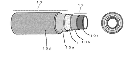
図1は、本発明の樹脂製チューブ(5層構造)の一例を示す斜視図及び断面図である。同図において、樹脂製チューブは、燃料等の流通し得る中空部分を中央に有し、燃料遮断層1と、外側層10a、内側層10b、最内層10c及び最外層10dから成る保護層10とを備える。燃料遮断層1の外側に外側層10aは配設され、燃料遮断層1の内側に内側層10bは配設される。
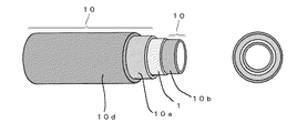
また、図2は、本発明の樹脂製チューブ(4層構造)の一例を示す斜視図及び断面図である。同図において、樹脂製チューブは、燃料等の流通し得る中空部分を中央に有し、燃料遮断層1と、外側層10a、内側層10b及び最外層10dから成る保護層10とを備える。燃料遮断層1の外側に外側層10aは配設され、燃料遮断層1の内側に内側層10bは配設される。
Here, the resin tube of the present invention will be described with specific examples.
FIG. 1 is a perspective view and a cross-sectional view showing an example of a resin tube (5-layer structure) of the present invention. In the figure, a resin tube has a hollow portion through which fuel or the like can flow in the center, and includes a
Moreover, FIG. 2 is the perspective view and sectional drawing which show an example of the resin-made tubes (4 layer structure) of this invention. In the figure, a resin tube has a hollow portion through which fuel or the like can flow, and includes a
図1を参照して説明すると、燃料遮断層1を、PBN含有層とすることにより、通常のガソリン燃料の他、エタノールやメタノールなどのアルコールを含む混合燃料をチューブ内に流通させても、優れた耐燃料透過性を有する樹脂製チューブとなる。
更に、このPBN含有層と接する層、即ち外側層10a及び内側層10bの双方を、PBNとPTMGとから成る共重合体(以下、PBNエラストマと称す。)含有層とすることにより、最内層10cや最外層10dを、安価なPBT含有層及びPBTセグメントを含む他の共重合体(以下、PBTエラストマと称す。)含有層の一方又は双方としたときに、PBN含有層から成る燃料遮断層1に強固に接着することができ、その結果、経済的に安価な樹脂製チューブを製造することが可能となる。
なお、PBN含有層、PBNエラストマ含有層、PBT含有層及びPBTエラストマ含有層と記載しているが、それぞれPBN層、PBNエラストマ層、PBT層及びPBTエラストマ層の場合も含まれることは言うまでもない。
If it demonstrates with reference to FIG. 1, even if it distribute | circulates the mixed fuel containing alcohol, such as ethanol and methanol other than normal gasoline fuel, it is excellent by making the
Furthermore, the innermost layer 10c is formed by making the layer in contact with the PBN-containing layer, that is, both the outer layer 10a and the inner layer 10b, a copolymer-containing layer composed of PBN and PTMG (hereinafter referred to as PBN elastomer). When the outermost layer 10d is one or both of an inexpensive PBT-containing layer and another copolymer (hereinafter referred to as PBT elastomer) containing PBT segment, the
In addition, although described as a PBN-containing layer, a PBN elastomer-containing layer, a PBT-containing layer, and a PBT elastomer-containing layer, it goes without saying that the case includes a PBN layer, a PBN elastomer layer, a PBT layer, and a PBT elastomer layer, respectively.
上述のように、本発明の樹脂製チューブは、燃料遮断層1及び保護層10の材料が、PBN、PBTエラストマ、PBNエラストマ及びPBTから成るポリエステル樹脂群から選択されるため、これらの混和性の高さから、例えば、製造工程中に出る端材や不要となった使用済みの樹脂製チューブは、構成する各層を分離することなく、同時に粉砕し再溶融して、所望の樹脂製部品に再利用することが可能であるなど、工程内、工程外を問わずリサイクルが容易であるという利点がある。
As described above, in the resin tube of the present invention, the material of the
また、燃料に接触する層は、最内層10c又は内側層10b(図2参照。)であり、双方の材料が、PBNエラストマ、PBTエラストマ及びPBTのうちから選択されるため、含エタノールガソリン、含メタノールガソリン、アミン系清浄材を含むガソリン又は劣化ガソリン、及びこれらの任意の混合物に対しても極めて優れた耐燃料油性を有する。 The layer in contact with the fuel is the innermost layer 10c or the inner layer 10b (see FIG. 2), and both materials are selected from PBN elastomer, PBT elastomer, and PBT. It has excellent fuel oil resistance even for methanol gasoline, gasoline containing amine-based cleaning materials or deteriorated gasoline, and any mixture thereof.
更に、燃料遮断層1、保護層10のいずれにおいても、金属等とのシール性が著しく向上するので、従来から用いているフッ素樹脂と異なり、樹脂製チューブに継手や金具の部品を挿入した場合でも、滑り難い樹脂製チューブとすることができる。
なお、上記劣化ガソリン等に対する耐燃料油性に関しては、上記列挙したポリエステル樹脂群のうちでは、PBNが最も優れ、次いでPBT、PBNエラストマ、PBTエラストマの順に優れる。したがって、最内層10cを、PBT含有層とすることが最も望ましく、PBNエラストマ含有層とすることが次に望ましい。
Furthermore, since both the
As for the fuel oil resistance against the above-described deteriorated gasoline and the like, PBN is the most excellent among the polyester resin groups listed above, and then PBT, PBN elastomer, and PBT elastomer are excellent in this order. Therefore, it is most desirable that the innermost layer 10c be a PBT-containing layer, and it is next desirable to be a PBN elastomer-containing layer.
更にまた、相溶性が逸脱しない限り、ポリアミド6やポリアミド66などのポリアミド樹脂類及びビスフェノールAポリカーボネートなどのポリカーボネート樹脂類を、燃料遮断層1及び保護層10の一方又は双方に混合することも可能である。この場合、更に安価な材料構成とすることができる。
なお、一般的には最内層10c又は内側層10bと相溶しにくいポリプロピレンやポリエチレンなどであっても、エポキシ基導入やマレイン酸変性等の処理をすることによって、上述したポリアミド樹脂類などと同様に、混合することも可能であり、この場合も同様に、更に安価な材料構成とすることができる。
Furthermore, as long as the compatibility does not deviate, polyamide resins such as polyamide 6 and polyamide 66 and polycarbonate resins such as bisphenol A polycarbonate can be mixed in one or both of the
In general, even for polypropylene, polyethylene, and the like that are hardly compatible with the innermost layer 10c or the inner layer 10b, the same treatment as that for the above-described polyamide resins and the like can be achieved by treatments such as epoxy group introduction and maleic acid modification. It is also possible to mix them, and in this case as well, a more inexpensive material structure can be obtained.
一方、このような本発明の樹脂製チューブは、柔軟なPBNエラストマ含有層を有するため、更に構成によってはPBTエラストマ含有層を有するため、例えば燃料系配管用チューブとして車両等へ取り付ける際には、屈曲させて容易に配置することができる。また、車両などにおける使用に際しても、保護層10の最も外側になる部分の材料が、PBNエラストマ、PBTエラストマ及びPBTのうちから選択されるため、燃料に接触する場合においても、十分な耐燃料油性を有する樹脂製チューブを得ることができる。
On the other hand, since the resin tube of the present invention has a flexible PBN elastomer-containing layer, and further has a PBT elastomer-containing layer depending on the configuration, for example, when attached to a vehicle or the like as a fuel system piping tube, It can be bent and placed easily. In addition, when used in a vehicle or the like, since the material of the outermost portion of the
また、材料硬度を選定する目安としては、上記エラストマ類においては、常温での曲げ弾性率が1.5GPa以下であることが好ましい。例えば、具体例として外径φ8mm、肉厚1mm程度の中空チューブでは、特に常温での曲げ弾性率が1.0GPa以下であることが好ましい。なお、材料の硬度は、樹脂製チューブとして所望する硬さに応じて適宜選択が可能である。 As a guideline for selecting the material hardness, it is preferable that the above-mentioned elastomers have a flexural modulus at room temperature of 1.5 GPa or less. For example, as a specific example, a hollow tube having an outer diameter of φ8 mm and a wall thickness of about 1 mm preferably has a flexural modulus of 1.0 GPa or less at room temperature. The hardness of the material can be appropriately selected according to the hardness desired for the resin tube.
本発明で使用するPBTエラストマとしては、PBTをハードセグメントとし、PTMGをソフトセグメントとするブロック型共重合体が、市場での入手性及び低温での柔軟性の面から望ましい。
また、これ以外の他のPBTエラストマとしては、酸成分としてテレフタル酸及びこのエステル形成性誘導体の一方又は双方と、水素添加ダイマー酸及びこのエステル形成性誘導体の一方又は双方とを含み、グリコール成分として1,4−ブタンジオールを含むランダム型共重合体が耐燃料油性の面から望ましい。
前者のブロック型共重合体は、上述の特性のうち、特に低温での柔軟性に優れているという面で、保護層10の一部又は全部へ適用することが望ましく。
後者のランダム型共重合体は、劣化ガソリンに対する耐燃料油性が優れているという点から、最内層10cへ適用することが望ましい。
As the PBT elastomer used in the present invention, a block copolymer having PBT as a hard segment and PTMG as a soft segment is desirable from the viewpoint of market availability and flexibility at low temperatures.
In addition, other PBT elastomers include terephthalic acid and one or both of this ester-forming derivative as an acid component and one or both of hydrogenated dimer acid and this ester-forming derivative as a glycol component. A random copolymer containing 1,4-butanediol is desirable from the viewpoint of fuel oil resistance.
The former block-type copolymer is desirably applied to a part or all of the
The latter random copolymer is preferably applied to the innermost layer 10c from the viewpoint of excellent fuel oil resistance against deteriorated gasoline.
上記2種類のPBTエラストマの更なる改良仕様として、PBTセグメントを含む共重合体が、酸成分としてテレフタル酸及びこのエステル形成性誘導体の一方又は双方と、水素添加ダイマー酸及びこのエステル形成性誘導体の一方又は双方とを含み、グリコール成分として1,4−ブタンジオールを含む共重合体ポリエステルにPTMGを共重合した共重合ポリエステルであってもよく、このような仕様にした場合は、保護層10のうちいずれの層にも適用可能である。また、このような改良を施したPBTエラストマの耐燃料油性は、PBTよりは劣るものの、PBNエラストマと同等以上である。 As a further improvement specification of the above two types of PBT elastomers, a copolymer containing a PBT segment may contain terephthalic acid and one or both of its ester-forming derivatives as an acid component, hydrogenated dimer acid and this ester-forming derivative. One or both of them may be a copolyester obtained by copolymerizing PTMG with a copolyester containing 1,4-butanediol as a glycol component. Applicable to any of these layers. Further, the fuel oil resistance of the PBT elastomer subjected to such an improvement is equal to or higher than that of the PBN elastomer although it is inferior to that of the PBT.
また、上記PBTエラストマがブロック型、ランダム型のいずれであっても、燃料遮断層1中のPBNと溶融温度が近いために、同一のクロスヘッドを用いて樹脂製チューブを同時押出し成形することが可能となる。
更に、上記組合せにおいては、層間に高い接着性を得ることができ、熱及び燃料など外部からの入力に対して優れた接着性を有する。
このように、同種の材料を組み合わせた構成を採用することによって、上述したようにリサイクルが容易と成るばかりでなく、従来のように接着層を別に設ける必要がなくなる。また、接着層が必要ないために、上述したように、耐燃料透過性、耐燃料油性及び柔軟性等の他の性能を向上させることが可能となる。
Even if the PBT elastomer is a block type or a random type, since the melting temperature is close to that of the PBN in the
Furthermore, in the above combination, high adhesiveness can be obtained between the layers, and excellent adhesiveness to external input such as heat and fuel.
Thus, by adopting a configuration in which the same kind of materials are combined, not only recycling becomes easy as described above, but there is no need to separately provide an adhesive layer as in the prior art. Further, since the adhesive layer is not necessary, as described above, other performances such as fuel permeation resistance, fuel oil resistance and flexibility can be improved.
なお、上述した燃料遮断層1及び保護層10の構成材料は、特別なものである必要はなく、市場で容易に入手できるものを使用できる。また、必要に応じて、耐熱性や耐加水分解性を適宜付与したり、フィラーなどを混入して導電性を付与したり、無機材料等を混入して強化することが可能である。
特に、最内層10cの樹脂にケッチェンブラック等の導電性フィラーをその体積固有抵抗が102〜106Ω・cmの範囲となるように混入すれば、流れの速い流体が流通する配管、例えば車両のフィードラインに適用しても、流動帯電を防止することが可能となり、好適である。
In addition, the constituent material of the
In particular, if a conductive filler such as ketjen black is mixed in the resin of the innermost layer 10c so that its volume resistivity is in the range of 10 2 to 10 6 Ω · cm, a pipe through which a fast-flowing fluid flows, for example, Even if it is applied to a feed line of a vehicle, it is possible to prevent flow electrification, which is preferable.
なお、本発明の樹脂製チューブは、PBN含有層、PBNエラストマ含有層、PBT含有層及びPBTエラストマ含有層の一方又は双方を有する多層構造の管状樹脂層を備え、PBN含有層がPBNエラストマ含有層により挟まれていれば、図1又は2に示すような代表的な構造に限定されず、用途や要求性能に応じて、更に複数の燃料遮断層や保護層を有していてもよく、詳しくは後述するが蛇腹構造を備えていてもよい。 The resin tube of the present invention includes a tubular resin layer having a multilayer structure including one or both of a PBN-containing layer, a PBN elastomer-containing layer, a PBT-containing layer, and a PBT elastomer-containing layer, and the PBN-containing layer is a PBN elastomer-containing layer. 1 is not limited to a typical structure as shown in FIG. 1 or 2, and may further have a plurality of fuel cutoff layers and protective layers according to the application and required performance. As will be described later, a bellows structure may be provided.
一方、上述のチューブ構成において、長さ方向にわたって、蛇腹構造の部分を設けることが望ましい。これにより、組付け時に有利な柔軟性及び使用時において十分な屈曲性の一方又は双方を与えることができ、直径10mm以上の配管、例えば車両の燃料システムにおけるベントホース等にも使用可能となり、広範な応用が可能となる。
このように、本発明の樹脂製チューブは、ガソリン燃料に限られず含アルコール燃料に対しても、優れた耐燃料透過性、即ち高い燃料遮断性を有することなどから、車両用の燃料配管として使用することが望ましい。
On the other hand, in the above-described tube configuration, it is desirable to provide a bellows structure portion over the length direction. As a result, it is possible to provide one or both of an advantageous flexibility at the time of assembly and sufficient flexibility at the time of use, and it can be used for piping having a diameter of 10 mm or more, such as a vent hose in a fuel system of a vehicle. Application becomes possible.
Thus, the resin tube of the present invention is used not only for gasoline fuel but also for alcohol-containing fuel, because it has excellent fuel permeation resistance, that is, high fuel cutoff, etc., and is therefore used as a fuel pipe for vehicles. It is desirable to do.
また、各層の層厚比率は特に限定されず、所望の厚さ比率で樹脂製チューブを製造することが可能である。特に、押出し成形で製造するときの安定性及び耐燃料透過性を確保するという面から、各層の層厚割合が全層厚(樹脂製チューブの厚さ)に対して5%以上であることが好ましく、且つ燃料遮断層の保護としての面から、燃料遮断層の層厚割合は全層厚に対して5〜20%の割合であることが好ましい。例えば、肉厚1mmの中空チューブであって、図1のような5層構造のチューブにおいては、最内層10cが0.2mm、内側層10bが0.1mm、燃料遮断層1が0.1mm、外側層10aが0.1mm、最外層10dが0.5mmのような層構成が好適形態の1つである。
Moreover, the layer thickness ratio of each layer is not specifically limited, It is possible to manufacture a resin-made tube with a desired thickness ratio. In particular, the thickness ratio of each layer is 5% or more with respect to the total layer thickness (the thickness of the resin tube) in terms of ensuring stability and resistance to fuel permeation when manufactured by extrusion molding. In terms of protection of the fuel cutoff layer, the layer thickness ratio of the fuel cutoff layer is preferably 5 to 20% of the total layer thickness. For example, a hollow tube having a thickness of 1 mm, and in a tube having a five-layer structure as shown in FIG. 1, the innermost layer 10c is 0.2 mm, the inner layer 10b is 0.1 mm, the
更に、燃料遮断層1であるPBN含有層を樹脂製チューブの全管状樹脂層の合計厚みのほぼ中央の位置に配設させることがより望ましい。なお、「PBN含有層を樹脂製チューブの全管状樹脂層の合計厚みのほぼ中央の位置に配設させる」とは、PBN含有層を全層厚のほぼ1/2の位置、例えば、全層厚1mmの場合は、0.5mmの位置を含むようにPBN含有層が配置している状態であり、完全に中央となる層構成が特に望ましい。
このような層構成の一例として、肉厚1mmの中空チューブで図1のような5層構造のチューブにおいては、最内層10cが0.3mm、内側層10bが0.15mm、燃料遮断層1が0.1mm、外側層10aが0.1mm、最外層10dが0.35mmのものを挙げることができ、このような場合、更に優れた低温衝撃性を確保することができる。
なお、樹脂製チューブの外径は、流通媒体の種類により異なるが、代表的には、3〜40mm程度であり、層厚は0.5〜3mm程度が一般的である。また、必要に応じて層厚は適宜改変することができる。
Furthermore, it is more desirable to dispose the PBN-containing layer that is the
As an example of such a layer structure, in a hollow tube having a thickness of 1 mm and a five-layer structure as shown in FIG. 1, the innermost layer 10c is 0.3 mm, the inner layer 10b is 0.15 mm, and the
The outer diameter of the resin tube varies depending on the type of the distribution medium, but is typically about 3 to 40 mm, and the layer thickness is generally about 0.5 to 3 mm. Further, the layer thickness can be appropriately modified as necessary.
以下、本発明を実施例及び比較例により更に詳細に説明する。 Hereinafter, the present invention will be described in more detail with reference to examples and comparative examples.
(実施例1)
最内層としてPBT(ポリプラスチック株式会社製;700FP)、中間層として内層側から、PBNエラストマ(帝人化成株式会社製;L4310AN)、PBN(帝人化成株式会社製;TQB−OT)、PBNエラストマ(帝人化成株式会社製;L4310AN)、最外層としてPBTエラストマ(東レデュポン株式会社製;ハイトレル 5577)を最内層側から層厚比0.2:0.1:0.1:0.1:0.5で押し出し、図1に示すような5層構造の本例の樹脂製チューブ(押出し外径:8mm、内径:6mm)を得た。
(Example 1)
PBT (made by Polyplastics Co., Ltd .; 700FP) as the innermost layer, and PBN elastomer (made by Teijin Chemicals Co., Ltd .; L4310AN), PBN (made by Teijin Chemicals Co., Ltd .; TQB-OT), PBN elastomer (Teijin) from the inner layer side as the intermediate layer Kasei Co., Ltd .; L4310AN), and PBT elastomer (manufactured by Toray DuPont Co., Ltd .; Hytrel 5577) as the outermost layer, layer thickness ratio 0.2: 0.1: 0.1: 0.1: 0.5 from the innermost layer side To obtain a resin tube (extruded outer diameter: 8 mm, inner diameter: 6 mm) of this example having a five-layer structure as shown in FIG.
(実施例2)
実施例1の最内層をPBTとPTMGのブロック共重合体であるPBTエラストマ(東レデュポン株式会社製、ハイトレル 7277)とした以外は実施例1と同一の5層構造を採用し、本例の樹脂製チューブを得た。
(Example 2)
The resin of this example adopts the same five-layer structure as Example 1 except that the innermost layer of Example 1 is PBT elastomer (Hytorel 7277 manufactured by Toray DuPont Co., Ltd.), which is a block copolymer of PBT and PTMG. A tube was obtained.
(実施例3)
実施例1の最内層をテレフタル酸/水素添加ダイマー酸/1,4−ブタンジオールから成るランダム共重合体(カネボウ合繊株式会社製、PBTS01562)とした以外は実施例1と同一の5層構造を採用し、本例の樹脂製チューブを得た。
(Example 3)
The same five-layer structure as in Example 1 except that the innermost layer of Example 1 was a random copolymer composed of terephthalic acid / hydrogenated dimer acid / 1,4-butanediol (manufactured by Kanebo Gosei Co., Ltd., PBTS01562). The resin tube of this example was obtained.
(実施例4)
実施例1の最内層をテレフタル酸/水素添加ダイマー酸/1,4−ブタンジオールから成るランダム共重合体とPTMGとの共重合体(カネボウ合繊株式会社製、PBTS01564)とした以外は実施例1と同一の5層構造を採用し、本例の樹脂製チューブを得た。
Example 4
Example 1 except that the innermost layer of Example 1 was a copolymer of a random copolymer composed of terephthalic acid / hydrogenated dimer acid / 1,4-butanediol and PTMG (manufactured by Kanebo Gosei Co., Ltd., PBTS01564). The same five-layer structure was adopted to obtain a resin tube of this example.
(実施例5)
実施例1の最内層をテレフタル酸/水素添加ダイマー酸/1,4−ブタンジオールから成るランダム共重合体とPTMGとの共重合体にケッチェンブラックを6%混練した樹脂(カネボウ合繊株式会社製、PBTS01563)とした以外は実施例1と同一の5層構造を採用し、本例の樹脂製チューブを得た。
(Example 5)
A resin obtained by kneading 6% ketjen black into a random copolymer of terephthalic acid / hydrogenated dimer acid / 1,4-butanediol and PTMG as the innermost layer of Example 1 (manufactured by Kanebo Gosei Co., Ltd.) The same five-layer structure as in Example 1 was adopted except that PBTS01563) was used, and a resin tube of this example was obtained.
(実施例6)
実施例2の層厚比を最内層側から0.35:0.1:0.1:0.1:0.35とした以外は実施例2と同一の5層構造を採用し、本例の樹脂製チューブを得た。
(Example 6)
This example employs the same five-layer structure as Example 2 except that the layer thickness ratio of Example 2 is set to 0.35: 0.1: 0.1: 0.1: 0.35 from the innermost layer side. A resin tube was obtained.
(実施例7)
蛇腹部を設けた以外は実施例2と同一の5層構造を採用し、本例の樹脂製チューブ(ストレート部の外径:16mm、内径:13mm、蛇腹部の外径:22mm)を得た。
(Example 7)
The same five-layer structure as in Example 2 was adopted except that the bellows portion was provided, and the resin tube of this example (outer diameter of straight portion: 16 mm, inner diameter: 13 mm, outer diameter of bellows portion: 22 mm) was obtained. .
(比較例1)
内層にエチレンテトラフルオロエチレン共重合体(ETFE)、中間層にETFEとポリアミド12(PA12)の混合物、外層にPA12を用いて、内層:中間層:外層=1.5:1.5:7(層厚比率)で押し出し、3層構造の本例の樹脂製チューブ(押出し外径:8mm、内径:6mm)を得た。
(Comparative Example 1)
An inner layer: intermediate layer: outer layer = 1.5: 1.5: 7 (ethylene tetrafluoroethylene copolymer (ETFE) for the inner layer, a mixture of ETFE and polyamide 12 (PA12) for the intermediate layer, and PA12 for the outer layer) The resin tube of this example having a three-layer structure (extruded outer diameter: 8 mm, inner diameter: 6 mm) was obtained by extrusion at a layer thickness ratio.
(比較例2)
ポリアミド11(PA11)のみで単層の本例の樹脂製チューブ(押出し外径:8mm、内径:6mm)を得た。
上記各例の樹脂製チューブの仕様を表1に示す。なお、表1中おいて、中間層1とは内側層10b、中間層2とは燃料遮断層1、中間層3とは外側層10aを表す。
(Comparative Example 2)
A single-layer resin tube of this example (extruded outer diameter: 8 mm, inner diameter: 6 mm) was obtained using only polyamide 11 (PA11).
Table 1 shows the specifications of the resin tube in each of the above examples. In Table 1, the

[性能評価]
(剥離強度試験)
上記各例の樹脂製チューブから1インチ幅の試験片を採取し、JIS−K6256の180°剥離試験を行った。なお、比較例1においては、内層と中間層の界面で測定を行った。
[Performance evaluation]
(Peel strength test)
A test piece having a width of 1 inch was collected from the resin tube in each of the above examples, and a 180 ° peel test of JIS-K6256 was performed. In Comparative Example 1, measurement was performed at the interface between the inner layer and the intermediate layer.
(耐燃料透過性能試験)
上記各例の樹脂製チューブと同一の構成の材料を平板状に押出し、その平板(チューブと同じ層厚比で層厚合計値が1mmである。)を用いて耐燃料透過性試験を行った。ここで、耐燃料透過性能については、φ70mmの円盤状に打ち抜いた試料を、ガソリン又は含アルコール燃料の60℃雰囲気下での規定時間(800時間)後の燃料透過量を測定した。なお、ガソリンは、市販のレギュラーガソリン(製造会社:新日本石油株式会社、商品名:シルバーN)を用い、含アルコール燃料は、このレギュラーガソリン90体積部とエタノール10体積部を混合したものを用いた。
(Fuel resistance test)
A material having the same configuration as that of the resin tube in each of the above examples was extruded into a flat plate shape, and a fuel permeation resistance test was performed using the flat plate (the same layer thickness ratio as the tube and a total layer thickness value of 1 mm). . Here, with respect to the fuel permeation resistance, a fuel permeation amount after a specified time (800 hours) in a 60 ° C. atmosphere of gasoline or alcohol-containing fuel was measured for a sample punched out into a disk shape of φ70 mm. In addition, commercially available regular gasoline (manufacturer: Shin Nippon Oil Co., Ltd., trade name: Silver N) is used for gasoline, and alcohol-containing fuel is a mixture of 90 parts by volume of regular gasoline and 10 parts by volume of ethanol. It was.
(低温衝撃性試験)
JASO M317−1986 8.9項に記載の試験方法により、即ち−40℃雰囲気において、質量:0.45kg、先端R=16mmの圧子を高さ305mmより樹脂製チューブに落下させ、低温衝撃性を測定した。
(Low temperature impact test)
In accordance with the test method described in JASO M317-1986 8.9, that is, in an atmosphere of −40 ° C., an indenter having a mass of 0.45 kg and a tip R = 16 mm is dropped from a height of 305 mm onto a resin tube, and low temperature impact resistance is obtained. It was measured.
得られた結果を表2に示す。表2中の◎、○、×は、比較例1の結果を○としたときの相対評価であり、◎はこれよりも優れていたもの、○は同等のもの、×は著しく劣るものを表す。 The obtained results are shown in Table 2. In Table 2, ◎, ○, × are relative evaluations when the result of Comparative Example 1 is ○, ◎ is better than this, ○ is equivalent, × is remarkably inferior. .
表2より、本発明の範囲に属する実施例1〜7は、本発明外の比較例1及び2と比較して同等以上の特性を示すことが分かる。
また、現時点では、低温衝撃性能(より低温領域における)の観点から、実施例4が最も良好な結果をもたらすものと思われる。
From Table 2, it can be seen that Examples 1 to 7 belonging to the scope of the present invention exhibit equivalent or better characteristics than Comparative Examples 1 and 2 outside the present invention.
At the present time, from the viewpoint of low-temperature impact performance (in a lower temperature region), Example 4 seems to give the best results.
以上、本発明を若干の実施例により詳細に説明したが、本発明はこれらに限定されるものではなく、本発明の要旨の範囲で種々の変形が可能である。
例えば、本発明に使用される各層の材料樹脂には、例えば酸化防止剤及び熱安定剤(例えば、ヒンダードフェノール、ヒドロキノン、チオエーテル又はホスファイト類及びこれらの置換体等、更にはこれらの任意の組合せを含む。)、紫外線吸収材(例えば、レゾルシノール、サリシレート、ベンゾトリアゾール及びベンゾフェノン等。)、滑剤及び離型剤(例えば、シリコン樹脂、モンタン酸及びその塩、ステアリン酸及びその塩、ステアリルアルコール及びステアリルアミド等。)、染料(例えば、ニトロシン等。)及び顔料(例えば、硫化カドミウム、フタロシアニン等。)を含む着色剤、添加剤添着液(例えば、シリコンオイル等。)、結晶核剤(例えば、タルク、カリオン等。)などを単独又は適宜組み合わせて添加することができる。
また、樹脂製チューブの断面形状は、代表的には円形又は楕円形であるが、これら以外の断面形状であってもよい。
更に、各層の材料を用いた多重管構造のチューブ以外の形状、例えば雨どいのような形状や、シート状で使用しても、耐燃料透過性が得られることは言うまでもない。
As mentioned above, although this invention was demonstrated in detail by some Examples, this invention is not limited to these, A various deformation | transformation is possible in the range of the summary of this invention.
For example, the material resin of each layer used in the present invention includes, for example, antioxidants and heat stabilizers (for example, hindered phenols, hydroquinones, thioethers or phosphites and substituted products thereof, and any of these optional materials. Combinations), ultraviolet absorbers (eg resorcinol, salicylate, benzotriazole and benzophenone), lubricants and mold release agents (eg silicone resin, montanic acid and salts thereof, stearic acid and salts thereof, stearyl alcohol and Stearylamide, etc.), dyes (for example, nitrosine, etc.) and pigments (for example, cadmium sulfide, phthalocyanine, etc.), additive additives (for example, silicon oil, etc.), crystal nucleating agents (for example, Talc, carion, etc.) can be added alone or in appropriate combination. That.
The cross-sectional shape of the resin tube is typically circular or elliptical, but may be other cross-sectional shapes.
Furthermore, it goes without saying that fuel permeation resistance can be obtained even when used in a shape other than a tube having a multi-tube structure using materials of each layer, such as a rain gutter or a sheet.
1 燃料遮断層
10 保護層
10a 外側層
10b 内側層
10c 最内層
10d 最外層
DESCRIPTION OF
Claims (8)
上記ポリブチレンナフタレート含有層の内側及び外側には、上記ポリブチレンナフタレートとポリテトラメチレングリコールとから成る共重合体含有層が配設されていることを特徴とする樹脂製チューブ。 Multilayer having a polybutylene naphthalate-containing layer, a copolymer-containing layer made of polybutylene naphthalate and polytetramethylene glycol, a polybutylene terephthalate-containing layer and / or another copolymer-containing layer containing a polybutylene terephthalate segment A resin tube having a tubular resin layer having a structure,
A resin tube characterized in that a copolymer-containing layer composed of the polybutylene naphthalate and polytetramethylene glycol is disposed inside and outside the polybutylene naphthalate-containing layer.
酸成分としてテレフタル酸及び/又はこのエステル形成性誘導体並びに水素添加ダイマー酸及び/又はこのエステル形成性誘導体を含み、グリコール成分として1,4−ブタンジオールを含む共重合ポリエステルと、
ポリテトラメチレングリコールと、を共重合した他の共重合ポリエステルを含むことを特徴とする請求項1〜3のいずれか1つの項に記載の樹脂製チューブ。 At least one of the other copolymer-containing layers containing the polybutylene terephthalate segment is
A copolyester comprising terephthalic acid and / or its ester-forming derivative and hydrogenated dimer acid and / or its ester-forming derivative as the acid component, and 1,4-butanediol as the glycol component;
The resinous tube according to any one of claims 1 to 3, further comprising another copolyester obtained by copolymerization with polytetramethylene glycol.
A tube for fuel system piping of a vehicle, comprising the resin tube according to any one of claims 1 to 7.
Priority Applications (3)
| Application Number | Priority Date | Filing Date | Title |
|---|---|---|---|
| JP2003315332A JP2005081663A (en) | 2003-09-08 | 2003-09-08 | Resin tubes and fuel piping tubes |
| EP04020862A EP1522780A1 (en) | 2003-09-08 | 2004-09-02 | Resin tube |
| US10/934,393 US20050053742A1 (en) | 2003-09-08 | 2004-09-07 | Resin tube |
Applications Claiming Priority (1)
| Application Number | Priority Date | Filing Date | Title |
|---|---|---|---|
| JP2003315332A JP2005081663A (en) | 2003-09-08 | 2003-09-08 | Resin tubes and fuel piping tubes |
Publications (1)
| Publication Number | Publication Date |
|---|---|
| JP2005081663A true JP2005081663A (en) | 2005-03-31 |
Family
ID=34225201
Family Applications (1)
| Application Number | Title | Priority Date | Filing Date |
|---|---|---|---|
| JP2003315332A Pending JP2005081663A (en) | 2003-09-08 | 2003-09-08 | Resin tubes and fuel piping tubes |
Country Status (3)
| Country | Link |
|---|---|
| US (1) | US20050053742A1 (en) |
| EP (1) | EP1522780A1 (en) |
| JP (1) | JP2005081663A (en) |
Families Citing this family (6)
| Publication number | Priority date | Publication date | Assignee | Title |
|---|---|---|---|---|
| JP5405862B2 (en) * | 2008-03-31 | 2014-02-05 | ウィンテックポリマー株式会社 | Multilayer tube |
| IT1394221B1 (en) * | 2009-05-15 | 2012-06-01 | Colbachini Spa | FLEXIBLE TUBE OF A PERFECT TYPE FOR THE TRANSPORT OF FLUID MATERIALS AND ELECTRIC CURRENT. |
| ES2544518B2 (en) * | 2014-01-30 | 2016-02-18 | Óscar Javier MUÑOZ RODRÍGUEZ | Versatile application procedure for protection in structures and infrastructures |
| JOP20190100A1 (en) | 2016-11-19 | 2019-05-01 | Potenza Therapeutics Inc | Anti-gitr antigen-binding proteins and methods of use thereof |
| JP7382149B2 (en) * | 2019-03-19 | 2023-11-16 | 住友理工株式会社 | multilayer tube |
| DE102023136201A1 (en) * | 2023-12-21 | 2025-06-26 | REHAU Industries SE & Co. KG | Thermally insulated pipe arrangement |
Family Cites Families (17)
| Publication number | Priority date | Publication date | Assignee | Title |
|---|---|---|---|---|
| US18328A (en) * | 1857-10-06 | Machine foe | ||
| US121560A (en) * | 1871-12-05 | Improvement in churns | ||
| US144744A (en) * | 1873-11-18 | Improvement in polishing tools | ||
| JPH05164273A (en) | 1991-12-07 | 1993-06-29 | Daikin Ind Ltd | Composite tube |
| DE4214383C2 (en) * | 1992-04-30 | 1996-08-14 | Inventa Ag | Coextruded multilayer polymer tube |
| EP0637509B1 (en) * | 1993-08-03 | 2002-10-23 | Nitta Moore Company | A tube for fuel transportation |
| JPH1030764A (en) | 1996-07-16 | 1998-02-03 | Tokai Rubber Ind Ltd | Fuel hose |
| JP3915213B2 (en) | 1996-12-16 | 2007-05-16 | 東レ株式会社 | Conductive resin composition |
| JPH11156970A (en) | 1997-11-26 | 1999-06-15 | Toray Ind Inc | Multi-layer hollow molded body |
| DE19831898B4 (en) * | 1998-07-16 | 2004-01-22 | Rasmussen Gmbh | Fluid line for fuels and fuel vapors |
| JP2000055248A (en) | 1998-08-10 | 2000-02-22 | Tokai Rubber Ind Ltd | Fuel hose and its manufacturing method |
| JP2000154890A (en) * | 1998-11-18 | 2000-06-06 | Tokai Rubber Ind Ltd | Tubing for fuel piping |
| JP3606204B2 (en) * | 2001-01-19 | 2005-01-05 | 日産自動車株式会社 | Resin tube |
| ES2220839T3 (en) * | 2001-04-10 | 2004-12-16 | Rasmussen Gmbh | MULTI-PIPE TUBE FOR HYDROCARBON FLUIDS. |
| JP4184697B2 (en) | 2001-04-12 | 2008-11-19 | 武田薬品工業株式会社 | Screening method |
| JP2003287165A (en) * | 2002-01-24 | 2003-10-10 | Tokai Rubber Ind Ltd | Hose for fuel |
| JP3606280B2 (en) * | 2002-07-16 | 2005-01-05 | 日産自動車株式会社 | Resin tubes and fuel piping tubes |
-
2003
- 2003-09-08 JP JP2003315332A patent/JP2005081663A/en active Pending
-
2004
- 2004-09-02 EP EP04020862A patent/EP1522780A1/en not_active Withdrawn
- 2004-09-07 US US10/934,393 patent/US20050053742A1/en not_active Abandoned
Also Published As
| Publication number | Publication date |
|---|---|
| US20050053742A1 (en) | 2005-03-10 |
| EP1522780A1 (en) | 2005-04-13 |
Similar Documents
| Publication | Publication Date | Title |
|---|---|---|
| JP3606204B2 (en) | Resin tube | |
| US5469892A (en) | Corrugated polymeric tubing having at least three layers with at least two respective layers composed of polymeric materials dissimilar to one another | |
| US5284184A (en) | Corrugated multi-layer tubing having at least one fluoroplastic layer | |
| CN103038058B (en) | Fuel inlet pipe made of resin, and method for producing same | |
| JP3126275B2 (en) | Fuel transfer tube | |
| JP4783028B2 (en) | Multilayer plastic pipe | |
| JP5092724B2 (en) | Laminated resin tubular body for hose inner pipe and refrigerant transport hose | |
| JP3606280B2 (en) | Resin tubes and fuel piping tubes | |
| JP3606213B2 (en) | Resin tube | |
| JP5474623B2 (en) | Fuel hose | |
| JP2005081663A (en) | Resin tubes and fuel piping tubes | |
| US10724659B2 (en) | Multilayer tube for guiding fuel fluid and method of manufacturing same | |
| US20040013835A1 (en) | Multilayer plastic tube for fluids used in motor vehicles | |
| CN100394094C (en) | Multi-layer resinous tube and multi-layer resinous container | |
| JP2009119682A (en) | Resin tube | |
| JP5212733B2 (en) | Multilayer hose | |
| JP2004052870A (en) | Bellows tube | |
| CN103890473B (en) | Resin-made fuel pipe | |
| WO2002029298A2 (en) | Convoluted tubing having a non-convoluted inner layer for handling hydrocarbon materials |
Legal Events
| Date | Code | Title | Description |
|---|---|---|---|
| A621 | Written request for application examination |
Free format text: JAPANESE INTERMEDIATE CODE: A621 Effective date: 20060628 |
|
| A977 | Report on retrieval |
Free format text: JAPANESE INTERMEDIATE CODE: A971007 Effective date: 20081203 |
|
| A131 | Notification of reasons for refusal |
Free format text: JAPANESE INTERMEDIATE CODE: A131 Effective date: 20090106 |
|
| A02 | Decision of refusal |
Free format text: JAPANESE INTERMEDIATE CODE: A02 Effective date: 20091027 |