JP2005076868A - Fluid control valve and droplet discharge device - Google Patents
Fluid control valve and droplet discharge device Download PDFInfo
- Publication number
- JP2005076868A JP2005076868A JP2003311851A JP2003311851A JP2005076868A JP 2005076868 A JP2005076868 A JP 2005076868A JP 2003311851 A JP2003311851 A JP 2003311851A JP 2003311851 A JP2003311851 A JP 2003311851A JP 2005076868 A JP2005076868 A JP 2005076868A
- Authority
- JP
- Japan
- Prior art keywords
- tank
- control valve
- fluid control
- cleaning liquid
- fluid
- Prior art date
- Legal status (The legal status is an assumption and is not a legal conclusion. Google has not performed a legal analysis and makes no representation as to the accuracy of the status listed.)
- Withdrawn
Links
- 239000012530 fluid Substances 0.000 title claims abstract description 73
- 239000007788 liquid Substances 0.000 claims description 109
- 238000004140 cleaning Methods 0.000 claims description 83
- 239000011344 liquid material Substances 0.000 claims description 11
- 238000007599 discharging Methods 0.000 claims description 6
- 230000007547 defect Effects 0.000 abstract description 3
- 238000001514 detection method Methods 0.000 description 34
- 239000011261 inert gas Substances 0.000 description 21
- 210000003128 head Anatomy 0.000 description 13
- 238000010586 diagram Methods 0.000 description 12
- 238000000034 method Methods 0.000 description 11
- 230000002265 prevention Effects 0.000 description 11
- 230000008030 elimination Effects 0.000 description 7
- 238000003379 elimination reaction Methods 0.000 description 7
- 230000002093 peripheral effect Effects 0.000 description 6
- 230000002950 deficient Effects 0.000 description 5
- 239000000463 material Substances 0.000 description 5
- 239000003595 mist Substances 0.000 description 5
- 238000003860 storage Methods 0.000 description 5
- 239000000126 substance Substances 0.000 description 5
- 230000001105 regulatory effect Effects 0.000 description 4
- 230000005611 electricity Effects 0.000 description 3
- 238000005498 polishing Methods 0.000 description 3
- 238000012545 processing Methods 0.000 description 3
- 238000005086 pumping Methods 0.000 description 3
- 230000003068 static effect Effects 0.000 description 3
- IJGRMHOSHXDMSA-UHFFFAOYSA-N Atomic nitrogen Chemical compound N#N IJGRMHOSHXDMSA-UHFFFAOYSA-N 0.000 description 2
- 238000005452 bending Methods 0.000 description 2
- 229910001873 dinitrogen Inorganic materials 0.000 description 2
- 238000012423 maintenance Methods 0.000 description 2
- 238000005192 partition Methods 0.000 description 2
- 238000003825 pressing Methods 0.000 description 2
- 229910001220 stainless steel Inorganic materials 0.000 description 2
- 239000010935 stainless steel Substances 0.000 description 2
- 239000000758 substrate Substances 0.000 description 2
- 238000004804 winding Methods 0.000 description 2
- 238000004891 communication Methods 0.000 description 1
- 238000011437 continuous method Methods 0.000 description 1
- 230000001276 controlling effect Effects 0.000 description 1
- 239000000428 dust Substances 0.000 description 1
- 230000000694 effects Effects 0.000 description 1
- 238000011010 flushing procedure Methods 0.000 description 1
- 239000011521 glass Substances 0.000 description 1
- 230000020169 heat generation Effects 0.000 description 1
- 238000004519 manufacturing process Methods 0.000 description 1
- 238000012986 modification Methods 0.000 description 1
- 230000004048 modification Effects 0.000 description 1
- 230000003020 moisturizing effect Effects 0.000 description 1
- 229920000728 polyester Polymers 0.000 description 1
- 239000007921 spray Substances 0.000 description 1
- 238000011144 upstream manufacturing Methods 0.000 description 1
- 239000002699 waste material Substances 0.000 description 1
- XLYOFNOQVPJJNP-UHFFFAOYSA-N water Substances O XLYOFNOQVPJJNP-UHFFFAOYSA-N 0.000 description 1
- 239000002759 woven fabric Substances 0.000 description 1
Images
Classifications
-
- B—PERFORMING OPERATIONS; TRANSPORTING
- B41—PRINTING; LINING MACHINES; TYPEWRITERS; STAMPS
- B41J—TYPEWRITERS; SELECTIVE PRINTING MECHANISMS, i.e. MECHANISMS PRINTING OTHERWISE THAN FROM A FORME; CORRECTION OF TYPOGRAPHICAL ERRORS
- B41J2/00—Typewriters or selective printing mechanisms characterised by the printing or marking process for which they are designed
- B41J2/005—Typewriters or selective printing mechanisms characterised by the printing or marking process for which they are designed characterised by bringing liquid or particles selectively into contact with a printing material
- B41J2/01—Ink jet
- B41J2/17—Ink jet characterised by ink handling
- B41J2/19—Ink jet characterised by ink handling for removing air bubbles
-
- B—PERFORMING OPERATIONS; TRANSPORTING
- B41—PRINTING; LINING MACHINES; TYPEWRITERS; STAMPS
- B41J—TYPEWRITERS; SELECTIVE PRINTING MECHANISMS, i.e. MECHANISMS PRINTING OTHERWISE THAN FROM A FORME; CORRECTION OF TYPOGRAPHICAL ERRORS
- B41J2/00—Typewriters or selective printing mechanisms characterised by the printing or marking process for which they are designed
- B41J2/005—Typewriters or selective printing mechanisms characterised by the printing or marking process for which they are designed characterised by bringing liquid or particles selectively into contact with a printing material
- B41J2/01—Ink jet
- B41J2/135—Nozzles
- B41J2/165—Prevention or detection of nozzle clogging, e.g. cleaning, capping or moistening for nozzles
- B41J2/16517—Cleaning of print head nozzles
- B41J2/16552—Cleaning of print head nozzles using cleaning fluids
-
- B—PERFORMING OPERATIONS; TRANSPORTING
- B41—PRINTING; LINING MACHINES; TYPEWRITERS; STAMPS
- B41J—TYPEWRITERS; SELECTIVE PRINTING MECHANISMS, i.e. MECHANISMS PRINTING OTHERWISE THAN FROM A FORME; CORRECTION OF TYPOGRAPHICAL ERRORS
- B41J2/00—Typewriters or selective printing mechanisms characterised by the printing or marking process for which they are designed
- B41J2/005—Typewriters or selective printing mechanisms characterised by the printing or marking process for which they are designed characterised by bringing liquid or particles selectively into contact with a printing material
- B41J2/01—Ink jet
- B41J2/17—Ink jet characterised by ink handling
- B41J2/175—Ink supply systems ; Circuit parts therefor
- B41J2/17596—Ink pumps, ink valves
Landscapes
- Coating Apparatus (AREA)
- Ink Jet (AREA)
- Valve Housings (AREA)
Abstract
Description
本発明は、流体制御弁および液滴吐出装置に関する。 The present invention relates to a fluid control valve and a droplet discharge device.
従来、流体の流れをオンオフ制御する流体制御弁としてさまざまな形式の流体制御弁が提案されている。
例えば、上述した流体制御弁として、流路に形成された弁座と、その弁座と当接または離間する弁体と、によりその内部を流過する流体の流れをオンオフ制御する流体制御弁が知られている(例えば、特許文献1参照。)。
For example, as the above-described fluid control valve, there is a fluid control valve that performs on / off control of the flow of fluid flowing through the inside by a valve seat formed in a flow path and a valve body that contacts or separates from the valve seat. It is known (for example, refer to Patent Document 1).
上述したように、従来の流体制御弁においては、流体制御弁に流体を初期充填すると、流体制御弁内に流体が完全に満たされず、内部に気泡が残る恐れがあった。また、流体制御弁内に複数の気泡が滞留すると、気泡同士が合体して大きな気泡となる恐れがあった。
このような気泡が流体と共に下流に流れ出すと、流体制御弁の下流に配置された他の流体機器における不具合の原因になる恐れがあるという問題があった。
As described above, in the conventional fluid control valve, when the fluid control valve is initially filled with fluid, the fluid control valve is not completely filled with fluid, and bubbles may remain inside. Further, when a plurality of bubbles stay in the fluid control valve, the bubbles may be combined to form a large bubble.
When such air bubbles flow downstream together with the fluid, there is a problem that it may cause a problem in another fluid device disposed downstream of the fluid control valve.
また、上述した流体制御弁を、各種基材へ溶液を吐出する液滴吐出装置におけるインクおよび洗浄液供給系に適用した場合、例えば、インク供給系に備えられた流体制御弁内に気泡が存在すると、その気泡が下流にインクと共に流れ出して、液滴を吐出する液滴吐出ヘッド内部に流入する。気泡が液滴吐出ヘッド内に侵入すると、気泡により液滴の吐出が不安定になる。
また、洗浄液供給系の流体制御弁内に滞留して大きくなった気泡が流路を塞ぐと、ヘッドクリーニング時の洗浄液の吐出量が不均一になり、十分に洗浄されず液滴吐出ヘッドのノズル部に汚れが残る恐れがある。
そのため、インク液滴の吐出時にインクが吐出されず描画抜けが発生したり、インクの飛行曲がりが発生したりして、液滴吐出ヘッドの初期吐出品質を確保できなくなってしまう問題があった。
Further, when the above-described fluid control valve is applied to an ink and cleaning liquid supply system in a droplet discharge device that discharges a solution to various base materials, for example, if bubbles exist in the fluid control valve provided in the ink supply system The bubbles flow out downstream with the ink and flow into the droplet discharge head that discharges the droplets. When bubbles enter the droplet discharge head, the droplet discharge becomes unstable due to the bubbles.
Also, if bubbles that stay in the fluid control valve of the cleaning liquid supply system become large and block the flow path, the amount of cleaning liquid discharged during head cleaning becomes uneven and the nozzle of the droplet discharge head is not cleaned sufficiently. Dirt may remain on the parts.
For this reason, when ink droplets are ejected, there is a problem that ink is not ejected, drawing omission occurs, or ink flight bending occurs, so that the initial ejection quality of the droplet ejection head cannot be ensured.
本発明は、上記の課題を解決するためになされたものであって、気泡が内部に滞留することを防止するとともに、下流に配置された他の流体機器が気泡に起因する不具合を発生することを防止することができる流体制御弁およびその流体制御弁を用いた液滴吐出装置を提供することを目的とする。 The present invention has been made to solve the above-described problem, and prevents bubbles from staying inside, and causes other fluid devices disposed downstream to generate defects due to the bubbles. It is an object of the present invention to provide a fluid control valve that can prevent liquid droplets and a droplet discharge device using the fluid control valve.
上記目的を達成するために、本発明の流体制御弁は、流体がその内部を流過するタンクと、タンクに流体が流入する流入口と、タンクから流体が流出する流出口と、流入口または流出口を開閉する弁体と、を備えた流体制御弁であって、流入口が流出口よりも下方に設けられていることを特徴とする。 In order to achieve the above object, a fluid control valve of the present invention includes a tank through which fluid flows, an inlet through which fluid flows into the tank, an outlet through which fluid flows out of the tank, an inlet or A fluid control valve including a valve body that opens and closes an outflow port, wherein the inflow port is provided below the outflow port.
すなわち、本発明の流体制御弁は、流入口が流出口よりも下方に設けられているため、流体制御弁に流体を初期充填すると、流出口より下方に設けられた流入口から流体が流入し、流入口より上方に設けられた流出口から空気が流出する。そのため、タンク内の空気は全て流出口から流出し、タンク内に気泡が滞留することがない。タンク内に気泡が滞留しないので、下流に気泡が流れ出ることがなく、下流に配置された他の流体機器が気泡に起因する不具合を発生することを防止することができる。 That is, since the inlet of the fluid control valve of the present invention is provided below the outlet, when the fluid is initially filled in the fluid control valve, the fluid flows from the inlet provided below the outlet. The air flows out from the outlet provided above the inlet. Therefore, all the air in the tank flows out from the outflow port, and bubbles do not stay in the tank. Since the bubbles do not stay in the tank, the bubbles do not flow downstream, and other fluid devices arranged downstream can be prevented from generating problems due to the bubbles.
上記の構成を実現するために、流入口がタンクの最下部に設けられていることが望ましい。
この構成によれば、流入口がタンクの最下部に設けられているため、流体はタンクの最下部から流入するため、流入口よりも下方に向かう流体の流れがなくなる。そのため、
気泡が下方に向かう流れに乗ってタンク内を循環することがなくなるため、気泡はより流出口に向かって流れやすくなり、タンク内に気泡が滞留しにくくなる。
In order to realize the above-described configuration, it is desirable that the inlet is provided at the lowest part of the tank.
According to this configuration, since the inflow port is provided at the lowermost part of the tank, the fluid flows in from the lowermost part of the tank, so that the fluid does not flow downward from the inflow port. for that reason,
Since the bubbles do not circulate in the tank along the downward flow, the bubbles are more likely to flow toward the outlet and the bubbles are less likely to stay in the tank.
上記の構成を実現するために、より具体的には、タンクには外部から流体を流入口に導く流入流路が備えられ、流入流路がタンクに向かって水平方向から上向きになるように配置されていることが望ましい。
この構成によれば、流入流路がタンクに向かって水平方向から上向きになるように配置されているため、流入流路内に気泡が滞留することがなくなり、タンク内に気泡が滞留しにくくなる。
In order to realize the above-described configuration, more specifically, the tank is provided with an inflow channel that guides fluid from the outside to the inflow port, and the inflow channel is arranged so as to face upward from the horizontal direction toward the tank. It is desirable that
According to this configuration, since the inflow channel is arranged so as to face upward from the horizontal direction toward the tank, bubbles do not stay in the inflow channel, and bubbles do not easily stay in the tank. .
上記の構成を実現するために、より具体的には、流出口がタンク上面の略中央部に設けられていることが望ましい。
この構成によれば、流出口がタンク上面の略中央部に設けられているため、タンク上面に集まった気泡が流体の流れによって流出口に集まりやすくなる。そのため、気泡がタンクから流出しやすくなり、タンク内に気泡が滞留しにくくなる。
More specifically, in order to realize the above configuration, it is desirable that the outflow port is provided at a substantially central portion of the upper surface of the tank.
According to this configuration, since the outflow port is provided at the substantially central portion of the upper surface of the tank, the bubbles gathered on the upper surface of the tank are easily collected at the outflow port due to the flow of fluid. For this reason, the bubbles easily flow out of the tank, and the bubbles are less likely to stay in the tank.
上記の構成を実現するために、より具体的には、タンク上面の形状が流出口に向けて上方に傾斜するテーパ形状に形成されていることが望ましい。
この構成によれば、タンク上面の形状が流出口に向けて上方に傾斜するテーパ形状に形成されているため、タンク内の気泡がタンク上面の傾斜に沿って上昇し流出口近傍に集まりやすくなる。そのため、気泡がタンクから流出しやすくなり、タンク内に気泡が滞留しにくくなる。
More specifically, in order to realize the above configuration, it is desirable that the shape of the upper surface of the tank be formed in a tapered shape that is inclined upward toward the outlet.
According to this configuration, the shape of the upper surface of the tank is formed in a tapered shape that is inclined upward toward the outflow port, so that bubbles in the tank rise along the inclination of the upper surface of the tank and easily collect in the vicinity of the outflow port. . For this reason, the bubbles easily flow out of the tank, and the bubbles are less likely to stay in the tank.
上記の構成を実現するために、より具体的には、タンク内部の面は親液処理が施されていることが望ましい。
この構成によれば、タンク内部の面は親液性が高くなっているため、液体が容易に付着できる。そのため、気泡は逆にタンク内部の面に付着しにくくなり、タンク内に気泡が滞留しにくくなる。
In order to realize the above configuration, more specifically, it is desirable that the surface inside the tank is subjected to lyophilic treatment.
According to this configuration, the surface inside the tank is highly lyophilic, so that the liquid can easily adhere. Therefore, the bubbles are less likely to adhere to the surface inside the tank, and the bubbles are less likely to stay in the tank.
上記の構成を実現するために、より具体的には、タンク内部の面には、化学研磨が施されていることが望ましい。
この構成によれば、タンク内部の面には化学研磨が施されているため、タンク内部の面に加工による損傷や加工目等の凹凸がなくなる。そのため、気泡がタンク内部の面に引っかかって付着しにくくなり、タンク内に気泡が滞留しにくくなる。
In order to realize the above-described configuration, more specifically, it is desirable that the surface inside the tank is subjected to chemical polishing.
According to this configuration, since the surface inside the tank is chemically polished, the surface inside the tank is free from damage due to processing and irregularities such as processing eyes. For this reason, the bubbles are difficult to adhere to the surface inside the tank, and the bubbles are less likely to stay in the tank.
上記目的を達成するために、本発明の液滴吐出装置は、流動性を有した液状体を吐出する複数のノズルが設けられた液滴吐出ヘッドと、ノズル周辺部をクリーニングする洗浄手段と、洗浄手段に洗浄液を吐出する洗浄液供給部と、液状体を液滴吐出装置に供給する第1供給流路と、洗浄液を前記洗浄液供給部に供給する第2供給流路と、第1供給流路を流れる液状体および第2供給流路を流れる洗浄液の流れを制御する流体制御弁と、を備えた液滴吐出装置であって、流体制御弁は上記本発明の流体制御弁を用いることを特徴とする。 In order to achieve the above object, a droplet discharge device of the present invention includes a droplet discharge head provided with a plurality of nozzles that discharge a fluid material having fluidity, a cleaning unit that cleans the peripheral portion of the nozzle, A cleaning liquid supply unit that discharges the cleaning liquid to the cleaning means, a first supply channel that supplies the liquid to the droplet discharge device, a second supply channel that supplies the cleaning liquid to the cleaning liquid supply unit, and a first supply channel And a fluid control valve for controlling the flow of the cleaning liquid flowing through the second supply flow path, wherein the fluid control valve uses the fluid control valve of the present invention. And
すなわち、本発明の液滴吐出装置は、上記本発明の流体制御弁を用いることにより、液滴吐出ヘッドおよび洗浄液供給部に流体制御弁内に滞留した気泡が流入することを防止することができる。そのため、液滴吐出ヘッドからの液状体吐出不良や、洗浄液供給部からの洗浄液吐出不良によるノズル周辺部のクリーニング不足を防止することができる。その結果、液状体の吐出不良による描画抜けや、ノズル周辺部のクリーニング不足による液状体の飛行曲がりを防止することができ、液滴吐出ヘッドの初期吐出品質を確保することができる。
また、流体制御弁内の気泡の滞留を防止することができるため、気泡を取り除く工程が不要となり、メンテナンス時間が削減でき生産性が向上する。
That is, the droplet discharge device of the present invention can prevent the bubbles remaining in the fluid control valve from flowing into the droplet discharge head and the cleaning liquid supply unit by using the fluid control valve of the present invention. . For this reason, it is possible to prevent insufficient cleaning of the peripheral portion of the nozzle due to defective discharge of the liquid material from the droplet discharge head and defective discharge of the cleaning liquid from the cleaning liquid supply unit. As a result, it is possible to prevent drawing omission due to poor discharge of the liquid material and flight bending of the liquid material due to insufficient cleaning of the peripheral portion of the nozzle, and it is possible to ensure the initial discharge quality of the droplet discharge head.
Further, since bubbles can be prevented from staying in the fluid control valve, a process for removing the bubbles is not required, maintenance time can be reduced, and productivity is improved.
以下、本発明における実施の形態について図1から図6を参照して説明する。
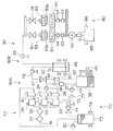
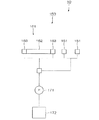
図1は本実施の形態における液滴吐出装置の概略構成図である。図2は、本実施の形態における液滴吐出装置のドット抜け検出・防止ユニットの概略構成図である。
液滴吐出装置10は、図1および図2に示すように、液滴吐出ユニット30と、キャップユニット60と、ワイピングユニット(洗浄手段)70と、ドット抜け検出・防止ユニット150とから概略構成されている。
液滴吐出ユニット30は、液滴吐出ヘッド53からインク液滴Rを基板(ガラス基板。以下、ウェハWfと称する)上の所定の位置に吐出、着弾させるユニットである。
液滴吐出ユニット30は、図1に示すように、所定圧力の不活性ガスを供給する加圧系30Aと、インク液滴を液滴吐出ヘッドに導くインク液滴供給系(第1供給流路)30Bと、インク液滴を吐出する液滴吐出ヘッド53とから概略構成されている。
Hereinafter, embodiments of the present invention will be described with reference to FIGS.
FIG. 1 is a schematic configuration diagram of a droplet discharge device according to the present embodiment. FIG. 2 is a schematic configuration diagram of a dot dropout detection / prevention unit of the droplet discharge device according to the present embodiment.
As shown in FIGS. 1 and 2, the
The
As shown in FIG. 1, the
この液滴吐出ユニット30では、加圧系30Aで不活性ガスg(例えば、窒素ガスなど)を所定圧力に調圧し、調圧された不活性ガスgをインク液滴供給系30Bに供給している。
まず、加圧系30Aについて説明する。
加圧系30Aには、不活性ガスg中に含まれる塵埃などの異物を除去するエアフィルタ31、36と、ミストを除去するミストセパレータ32と、圧力を適切に調圧するインク液滴圧送圧力調整弁33、33および洗浄液圧送圧力調整弁39と、インク液滴側残圧排気弁34、34および洗浄液側残圧排気弁40と、不活性ガスgの圧力を測定する不活性ガス圧力検出センサ37と、が備えられている。
加圧系30Aにおいては、まず、窒素ガス等の不活性ガスgがエアフィルタ31に供給され、不活性ガスg中に含まれる異物が除去される。その後、不活性ガスgはミストセパレータ32において、その中に含まれるミストが除去される。
異物およびミストが除去された不活性ガスgは、液滴吐出装置10の作業内容に応じて、インク液滴供給系30Bと、後述する洗浄液供給系(第2供給流路)70Aとのどちらか一方に送られる。このインク液滴供給系30Bと、洗浄液供給系70Aとの切替には、後述するインク液圧送ON/OFF切替弁(流体制御弁)47と、洗浄液ON/OFF切替弁(流体制御弁)71とを交互にON/OFF切り替えることによって行われる。これらインク液圧送ON/OFF切替弁47、洗浄液ON/OFF切替弁71の2つのON/OFF切替弁およびヘッド気泡排除弁54には、本発明のON/OFF切替弁(流体制御弁)が用いられている。
In the
First, the
The
In
The inert gas g from which foreign matter and mist have been removed is either an ink
すなわち、インク液圧送ON/OFF切替弁47をON、洗浄液ON/OFF切替弁71をOFFにして、インク液滴供給系30Bに不活性ガスgを圧送する場合、不活性ガスgは液滴圧送圧力調整弁33に供給され、所定の圧力に調圧される。調圧された不活性ガスgは、インク液滴側残圧排気弁34、エアフィルタ36を流過し、不活性ガス圧力検出センサ37において供給圧チェックされてから、インク液滴加圧タンク38へと供給される。
That is, when the ink liquid pressure feed ON /
一方、インク液圧送ON/OFF切替弁47をOFF、洗浄液ON/OFF切替弁71をONにして、洗浄液供給系70Aに不活性ガスgを圧送する場合、不活性ガスgは洗浄液圧送圧力調整弁39に供給され、所定の圧力に調圧される。調圧された不活性ガスgは、洗浄液側残圧排気弁40、エアフィルタ71を流過し、不活性ガス圧力検出センサ72において供給圧チェックされ、洗浄液圧送タンク73へと供給される。
On the other hand, when the ink liquid pressure feed ON /
次に、インク供給系30Bについて説明する。
インク液滴供給系30Bは、図1に示すように、インク液滴を貯溜するインク液滴加圧タンク38およびメインタンク48と、インク液滴の圧力を測定するインク液圧送圧力検出センサ46と、インク液滴の圧送を制御するインク液圧送ON/OFF切替弁47と、液滴吐出ヘッド53内の気泡を排除する際に使用するヘッド部気泡排除弁54とから概略構成されている。
インク液滴加圧タンク38には、タンク内の過剰な圧力を逃がすタンク排圧弁44と、インク液滴の液面位置を検出することにより、インク液滴が所定量あるかないかを確認するインク液滴有無検出センサ45と、が備えられている。これにより、例えば、インク液滴加圧タンク38内のインク液滴残量が所定レベルを下回った場合には、インク液滴有無検出センサ45がこれを検知し、この検知信号に基づいて、インク液滴加圧タンク38にインク液滴が補給される。
メインタンク48には、エアフィルタ50と、メインタンク部上限検出センサ51と、インク液滴液面制御用検出センサ52と、が備えられている。これにより、例えば、メインタンク48内のインク液滴液面が所定レベルを超えた場合には、メインタンク部上限検出センサ51がこれを検出し、この検知信号に基づいて、メインタンク48へのインク液滴の供給が止められる。また、インク液滴液面制御用検出センサ52は、複数の液滴吐出ヘッド53の各ノズル面53aに対するメインタンク48内のインク液滴液面の水頭値headを所定の範囲(例えば25mm±0.5mm)内に調整するための検出センサである。
また、インク液圧送ON/OFF切替弁47とメインタンク48との間には静電気を逃がすための流路部アース継手49が配置され、メインタンク48とヘッド部気泡排除弁54との間には同じく静電気を逃がすための流路部アース継手55が配置されている。
Next, the
As shown in FIG. 1, the ink
In the ink
The
A flow path ground joint 49 for discharging static electricity is arranged between the ink liquid pressure ON /
インク液滴供給系30Bのインク液滴加圧タンク38に不活性ガスgが供給されると、不活性ガスgによりインク液滴液面が下方に押圧され、インク液滴加圧タンク38から圧送される。圧送されたインク液滴はインク液圧送圧力検出センサ46において測圧され、インク液圧送ON/OFF切替弁47を流過し、メインタンク48に供給される。
When the inert gas g is supplied to the ink
メインタンク48に供給されたインク液滴は、メインタンク48からさらにヘッド部気泡排除弁54を経て、液滴吐出ヘッド53に供給される。
ヘッド部気泡排除弁54は、液滴吐出ヘッド53の上流側流路を閉じることにより、該液滴吐出ヘッド53内の液滴を後述のキャップユニット60で吸引する際の吸引流速を高め、液滴吐出ヘッド53内の気泡を速く排気することができるようになっている。
The ink droplets supplied to the
The head
次に、液滴吐出ヘッド53について説明する。
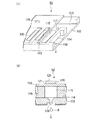
図3(a)、(b)は液滴吐出ヘッドの概略構成図である。
本実施形態では、液滴吐出法としてインクジェット法を用いることにする。このインクジェット法は、液滴吐出ヘッド53として、例えば図3(a)に示すようにステンレス製のノズルプレート112と振動板113とを備え、両者を仕切部材(リザーバプレート)114を介して接合したものを用いる。ノズルプレート112と振動板113との間には、仕切部材114によって複数のキャビティ115…とリザーバ116とが形成されており、これらキャビティ115…とリザーバ116とは流路117を介して連通している。
Next, the
3A and 3B are schematic configuration diagrams of the droplet discharge head.
In the present embodiment, an inkjet method is used as a droplet discharge method. As shown in FIG. 3A, for example, the ink jet method includes a stainless
各キャビティ115とリザーバ116の内部とは吐出するための液状体(レンズ材料)で満たされるようになっており、これらの間の流路117はリザーバ116からキャビティ115に液状体を供給する供給口として機能するようになっている。また、ノズルプレート112には、キャビティ115から液状体を噴射するための孔状のノズル118が縦横に整列した状態で複数形成されている。一方、振動板113には、リザーバ116内に開口する孔119が形成されており、この孔119には液状体タンク(図示せず)がチューブ(図示せず)を介して接続されるようになっている。
Each
また、振動板113のキャビティ115に向く面と反対の側の面上には、図3(b)に示すように圧電素子(ピエゾ素子)120が接合されている。この圧電素子120は、一対の電極121、121間に挟持され、通電により外側に突出するようにして撓曲するよう構成されたもので、本発明における吐出手段として機能するものである。
Also, a piezoelectric element (piezo element) 120 is bonded to the surface of the
このような構成のもとに圧電素子120が接合された振動板113は、圧電素子120と一体になって同時に外側へ撓曲し、これによりキャビティ115の容積を増大させる。すると、キャビティ115内とリザーバ116内とが連通しており、リザーバ116内に液状体が充填されている場合には、キャビティ15内に増大した容積分に相当する液状体が、リザーバ116から流路117を介して流入する。
そして、このような状態から圧電素子120への通電を解除すると、圧電素子120と振動板113はともに元の形状に戻る。よって、キャビティ115も元の容積に戻ることから、キャビティ115内部の液状体の圧力が上昇し、ノズル118から液状体の液滴122が吐出される。
The
When the energization to the
なお、液滴吐出ヘッドの吐出手段としては、前記の圧電素子(ピエゾ素子)120を用いた電気機械変換体以外でもよく、例えば、エネルギー発生素子として電気熱変換体を用いた方式や、帯電制御型、加圧振動型といった連続方式、静電吸引方式、さらにはレーザなどの電磁波を照射して発熱させ、この発熱による作用で液状体を吐出させる方式を採用することもできる。 The discharge means of the droplet discharge head may be other than the electromechanical converter using the piezoelectric element (piezo element) 120, for example, a method using an electrothermal converter as an energy generating element, or charging control. It is also possible to adopt a continuous method such as a mold or a pressure vibration type, an electrostatic suction method, or a method in which an electromagnetic wave such as a laser is irradiated to generate heat and a liquid material is discharged by the action of this heat generation.
以上説明の液滴吐出ユニット30に続き、キャップユニット60について説明する。
キャップユニット60は、図1に示すように、液滴吐出ヘッド53に押し当てられるキャップ61と、液滴を吸引する液滴吸引ポンプ62と、吸引された液滴を貯溜する液滴再利用タンク65と、吸引圧力を調節するために使用されるニードルバルブ63および液滴吸引圧検出センサ64と、から概略構成されている。
液滴再利用タンク65には再利用タンク上限検出センサ66が備えられている。例えば、液滴再利用タンク65内の液面高さが所定レベルを超えると再利用タンク上限検出センサ66に検出され、この検出信号に基づき、液滴再利用タンク65内のインク液滴は再利用工程に移される。
Following the
As shown in FIG. 1, the cap unit 60 includes a
The
上述したキャップユニット60によれば、まず、各液滴吐出ヘッド53からの液滴Rの吐出開始前に、各液滴吐出ヘッド53のノズル面53aに対して真下よりキャップ61を押し当てる。そして、液滴吸引ポンプ62の吸引力を利用して、液滴吐出ヘッド53の各ノズルに負圧を加えてノズル面53aまで液滴を充填させたり、各ノズルの目詰まりを取るために各液滴吐出ヘッド53の各ノズルに負圧を加えて吸引したり、または製造を行わない待機時に、各ノズル内の液滴が乾燥することのないようにキャップ61でノズル面53を覆って保湿したりする。
According to the cap unit 60 described above, first, before starting the discharge of the droplet R from each
以上説明のキャップユニット60に続き、ワイピングユニット70について説明する。
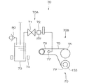
図4は、ワイピングユニットの概略構成を示す図である。
図1および図4に示すワイピングユニット70は、定期的あるいは随時に、前記各液滴吐出ヘッド53の各ノズル面53aを一括清掃するものである。
また、ワイピングユニット70は、図1および図4に示すように、洗浄液を供給する洗浄液供給系70Aと、ノズル面53aを洗浄するノズル面洗浄系70Bとから概略構成されている。
Following the cap unit 60 described above, the wiping
FIG. 4 is a diagram illustrating a schematic configuration of the wiping unit.
The wiping
Further, as shown in FIGS. 1 and 4, the wiping
洗浄液供給系70Aは、洗浄液を蓄える洗浄液タンク73と、洗浄液の流れを制御する洗浄液ON/OFF切替弁71と、後述するワイピングシート75に洗浄液を吹き付ける洗浄液供給部77と、から構成されている。洗浄液ON/OFF切替弁71と洗浄液供給部77との間には、流路から静電気を逃がすための流路部アース継手72が備えられている。
また、洗浄液タンク73には、洗浄液の液面位置を検出することにより、洗浄液が所定量あるかないかを確認する洗浄液有無検出センサ74と、タンク内の過剰な圧力を逃がすタンク排圧弁80が備えられている。例えば、洗浄液タンク73内の洗浄液残量が所定レベルを下回ると、洗浄液有無検出センサ74がこれを検知し、この検知信号に基づいて、洗浄液タンク73に洗浄液が補給される。
The cleaning
Further, the cleaning
ノズル面洗浄系70Bは、図4に示すように、各ノズル面53aを拭うワイピングシート75と、ワイピングシート75を各ノズル面53aに向けて押し付けるローラ76と、ワイピングシート75を供給する巻き出しローラ78と、各ノズル面53aを拭った後のワイピングシート75を巻き取る巻取りローラ79と、巻取りローラ79を回転駆動する電動モータ153とを備えて構成されている。
なお、ワイピングシート75としては、例えばポリエステル100%の織布が好適に用いられる。また、ローラ76はゴムローラであり、その周面に対する押圧力に対して反発する弾性を備えている。
As shown in FIG. 4, the nozzle
As the wiping
このワイピングユニット70の洗浄液供給系70Aによれば、上述したように、洗浄液圧送タンク73に調圧された不活性ガスgが供給される。そのため、洗浄液圧送タンク73内が加圧され、内部に貯留されている洗浄液が洗浄液ON/OFF切替弁71を流過して洗浄液供給部77へと圧送され、ワイピングシート75に吹き付けられる。
また、上述したノズル面洗浄系70Bによれば、巻き出しローラ78から巻き出されるワイピングシート75を各ノズル面53aに向かって供給しながらローラ76で押し付けることができ、ワイピングシート75の新しい清掃面を絶えず各ノズル面53aに対して供給することができる。しかも、ローラ76の押し付け力によりワイピングシート75を各ノズル面53aに押し付ける構成であるため、各ノズル面53aに対して清掃面を確実に当てることもできる。
According to the cleaning
Further, according to the nozzle
以上説明のワイピングユニット70に続き、ドット抜け検出・防止ユニット150について説明する。
図2に示すこのドット抜け検出・防止ユニット150は、各ノズルユニット53の各ノズルの目詰まりを調べ、防止するためのものである。
ドット抜け検出・防止ユニット150は、図2に示すように、ドット抜け検出部151と、ドット抜け防止部161と、ドット抜け検出部151およびドット抜け防止部161に接続された吸引ポンプ171と、吸引ポンプ171に吸引されたインク液滴を貯める廃液タンク172と、から概略構成されている。
ドット抜け検出部151には、その内部にレーザ光を出射するレーザ装置(図示せず)と、出射されたレーザ光を検知するレーザ検出部(図示せず)と、が備えられている。
ドット抜け防止部161は、ウェハWfをその上に載置するテーブル162と、テーブル162の端部に設けられた予備吐出部163とから概略構成されている。
Following the
This dot missing detection /
As shown in FIG. 2, the missing dot detection /
The
The dot
このドット抜け検出・防止ユニット150のドット抜け検出部151によれば、ドット抜け検出部151上方に各液滴吐出ヘッド53を移動させ、レーザ装置(図示せず)から出射されるレーザ光を遮るようにして各液滴吐出ヘッド53からインク液滴を捨て撃ちさせて検査を行うことができる。
例えば、捨て撃ちの指示をしたにもかかわらずレーザ検出部(図示せず)がレーザ光を検出し続ければ、ノズルが目詰まりを起こして液滴が出ておらず、製造品にドット抜けが生じる恐れがあると判断される。そして、前記キャップユニット60により問題となっている液滴吐出ヘッド53のノズルが吸引・目詰まり除去されるようになっている。
According to the dot
For example, if a laser detection unit (not shown) continues to detect laser light even though a throwing instruction has been given, the nozzle will be clogged and no liquid droplets will be produced, resulting in missing dots in the manufactured product. It is judged that it may occur. The nozzle of the
また、ドット抜け防止部161によれば、ウェハWfにインク液滴を吐出させる前に、予備吐出部163上方に各液滴吐出ヘッド53を移動させ、各液滴吐出ヘッド53からインク液滴を予備吐出(フラッシング)させることができる。つまり、インク液滴の飛行が不安定な吐出初期には、予備吐出部163にインク液滴を予備吐出させ、インク液滴の飛行が安定してから、ウェハWf上にインク液滴を吐出させることができ、その結果、ドット抜けを防止することができる。
Further, according to the dot
次に本実施の形態の特徴部分であるインク液圧送ON/OFF切替弁、洗浄液ON/OFF切替弁およびヘッド気泡排除弁54について説明する。
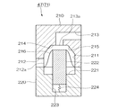
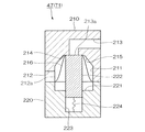
図5は、インク液圧送ON/OFF切替弁のON時の概略構成図である。図6は、インク液圧送ON/OFF切替弁のOFF時の概略構成図である。
なお、インク液圧送ON/OFF切替弁47、洗浄液ON/OFF切替弁71および
ヘッド気泡排除弁54の構成および作用、効果は略同一であるため、ここではインク液圧送ON/OFF切替弁47について説明し、洗浄液ON/OFF切替弁71およびヘッド気泡排除弁54の説明は省略する。
Next, the ink liquid pressure feed ON / OFF switching valve, the cleaning liquid ON / OFF switching valve, and the head
FIG. 5 is a schematic configuration diagram when the ink liquid pressure feed ON / OFF switching valve is ON. FIG. 6 is a schematic configuration diagram when the ink liquid pressure feed ON / OFF switching valve is OFF.
The configuration, operation, and effect of the ink liquid pressure ON /
インク液圧送ON/OFF切替弁47は、図5および図6に示すように、例えばステンレス材からなる上部筐体210と、下部筐体220とを組み合わせることにより概略構成されている。上部筐体210には、下部筐体220に向けて開口しているタンク211と、タンク211の側面最下部に接続する流入流路212と、タンク211の上面略中央部に接続する流出流路213とが形成されている。
下部筐体220には、上部筐体210に向けて開口している凹部221と、ダイヤフラム216を押し上げ弁座214と当接、離間する弁体222と、弁体222がその内部をスライド移動する弁体収納部223と、弁体収納部223の下面に設けられ弁体222を下方に向けて付勢するバネ224と、弁体収納部223に弁体222駆動用のエアを供給するエア供給部(図示せず)が設けられている。
As shown in FIGS. 5 and 6, the ink hydraulic pressure ON /
In the
タンク211の上面には、流出流路213の流出口213a周辺に後述する弁体222と当接する弁座214が形成され、弁座214に向かって上方に傾斜するテーパ面215が形成されている。タンク211の側面最下部には流入流路212の流入口212aが形成されている。タンク211の下部筐体220側の開口部には、この開口部を塞ぐように可撓性を持つダイヤフラム216が設けられている。また、タンク211の内面には、上部筐体210の材質(本実施例においてはステンレス)を溶かす化学薬品による化学研磨が施され、タンク211内面の加工目のような凹凸が除去されている。
なお、流入通路212は、本実施の形態においては略水平方向に設けられているが、タンク211に向かって上方に傾斜して設けられてもよい。このように流入流路212を上方に傾斜して設けることで、流入流路212内に気泡が滞留することを防止することができる。また、タンク211内面に親水性の被膜を形成したり、タンク211内面自体に親水性を持たせる処理を行ったりしてもよい。このような処理を行うことにより、タンク211内部の面の親液性が高くなり液体が容易に付着することができる。そのため、気泡は逆にタンク内部の面に付着しにくくなり、タンク内に気泡が滞留しにくくなる。
流出流路213は、まずタンク211から略垂直上方に設けられ、その後略水平方向に設けられているが、略水平方向に限られることなく、タンク211から外側に向かって上方に傾斜して設けられてもよい。このように流出流路213を上方に傾斜して設けることで、流出流路213内に気泡が滞留することを防止することができる。
On the upper surface of the
The
The
上述したインク液圧送ON/OFF切替弁47がON状態になると、図5に示すように、弁体収納部223へのエア供給が停止され、バネ224により弁体222が下方に引き寄せられる。すると、弁座214と弁体222とが離間し、インク液滴は弁座214と弁体222との間隙を流過して流出流路213に流入する。
また、インク液圧送ON/OFF切替弁47がOFF状態になると、図6に示すように、弁体収納部223へのエアが供給され、エアの圧力により弁体222が上方へ押し上げられる。すると、弁座214と弁体222とがダイヤフラム216を介して当接し、タンク211内のインク液滴の流出流路213への流入が止められる。
When the ink liquid pressure feed ON /
Further, when the ink liquid pressure ON /
上記の構成のインク液圧送ON/OFF切替弁47によれば、流入口212aが流出口213aよりも下方に設けられているため、インク液圧送ON/OFF切替弁47にインク液滴を初期充填する際には、流入口212aからインク液滴が流入し、流出口213aから空気が流出する。そのため、タンク211内の空気は全て流出口213aから流出し、タンク内に気泡が滞留することがない。タンク211内に気泡が滞留しないので、下流に気泡が流れ出ることがなく、下流に配置された液滴吐出ヘッド53が気泡に起因する不具合を発生することを防止することができる。
According to the ink liquid pressure feed ON /
また、流入口212aがタンク211の最下部に設けられているため、インク液滴はタンク211の最下部から流入し、流入口212aよりも下方に向かうインク液滴の流れがなくなる。そのため、気泡が下方に向かう流れに乗ってタンク211内を循環することがなくなり、気泡はより流出口に向かって流れやすくなるため、タンク211内に気泡が滞留しにくくなる。
In addition, since the
流出口213aがタンク211上面の略中央部に設けられ、かつタンク211上面の形状が流出口213aに向けて上方に傾斜するテーパ形状に形成されているため、タンク211内の気泡が流出口近傍に集まりやすくなっている。そのため、気泡がタンク211から流出しやすくなり、タンク211内に気泡が滞留しにくくなる。
The
タンク211内部の面が化学研磨により滑らかに仕上げ加工されているため、気泡がタンク211内部の面における加工目のような凹凸がなくなる。上記凹凸がなくなっているため、気泡がタンク211内部の面に付着しにくくなり、タンク211内に気泡が滞留しにくくなる。
Since the surface inside the
また、インク液圧送ON/OFF切替弁47、洗浄液ON/OFF切替弁71およびヘッド気泡排除弁54を用いた滴吐出装置10によれば、液滴吐出ヘッド53および洗浄液供給部77にインク液圧送ON/OFF切替弁47、洗浄液ON/OFF切替弁71およびヘッド気泡排除弁54内に滞留した気泡が流入することを防止することができる。そのため、液滴吐出ヘッド53からのインク液滴吐出不良や、洗浄液供給部77からの洗浄液吐出不良によるノズル118周辺部のクリーニング不足を防止することができる。
その結果、インク液滴の吐出不良による描画抜けや、ノズル118周辺部のクリーニング不足によるインク液滴の飛行曲がりを防止することができ、液滴吐出ヘッド53の初期吐出品質を確保することができる。
また、インク液圧送ON/OFF切替弁47、洗浄液ON/OFF切替弁71およびヘッド気泡排除弁54内の気泡の滞留を防止することができるため、気泡を取り除く工程が不要となり、メンテナンス時間が削減でき生産性が向上する。
Further, according to the
As a result, it is possible to prevent drawing omission due to defective ejection of ink droplets and flying deflection of ink droplets due to insufficient cleaning of the peripheral portion of the
In addition, it is possible to prevent air bubbles from staying in the ink liquid pressure ON /
なお、本発明の技術範囲は上記実施形態に限定されるものではなく、本発明の趣旨を逸脱しない範囲において種々の変更を加えることが可能である。
例えば、上記の実施の形態においては、この発明を液滴吐出装置に適応して説明したが、この発明は液滴吐出装置に限られることなく、その他各種の流体制御装置に適応できるものである。
The technical scope of the present invention is not limited to the above embodiment, and various modifications can be made without departing from the spirit of the present invention.
For example, in the above-described embodiment, the present invention has been described as being applied to a droplet discharge device. However, the present invention is not limited to a droplet discharge device, and can be applied to other various fluid control devices. .
10・・・液滴吐出装置、 30B・・・インク液滴供給系(第1供給流路)、 47・・・インク液圧送ON/OFF切替弁(流体制御弁)、 53・・・液滴吐出ヘッド、 70・・・ワイピングユニット(洗浄手段)、 70A・・・洗浄液供給系(第2供給流路)、 71・・・洗浄液ON/OFF切替弁(流体制御弁)、 77・・・洗浄液供給部、 118・・・ノズル、 211・・・タンク、 212a・・・流入口、 213a・・・流出口、 222・・・弁体
DESCRIPTION OF
Claims (8)
前記流入口が前記流出口よりも下方に設けられていることを特徴とする流体制御弁。 A tank through which the fluid flows, an inlet through which the fluid flows into the tank, an outlet through which the fluid flows out of the tank, and a valve body that opens and closes the inlet or the outlet. A fluid control valve,
The fluid control valve, wherein the inlet is provided below the outlet.
該流入流路が、前記タンクに向かって水平方向から上向きになるように配置されていることを特徴とする請求項1または2に記載の流体制御弁。 The tank is provided with an inflow channel for guiding fluid from the outside to the inlet,
The fluid control valve according to claim 1, wherein the inflow channel is disposed so as to face upward from a horizontal direction toward the tank.
前記ノズル周辺部をクリーニングする洗浄手段と、
該洗浄手段に洗浄液を吐出する洗浄液供給部と、
前記液状体を前記液滴吐出装置に供給する第1供給流路と、
前記洗浄液を前記洗浄液供給部に供給する第2供給流路と、
前記第1供給流路を流れる液状体および前記第2供給流路を流れる洗浄液の流れを制御する流体制御弁と、
を備えた液滴吐出装置であって、
前記流体制御弁は請求項1から7のいずれかに記載の流体制御弁を用いることを特徴とする液滴吐出装置。 A droplet discharge head provided with a plurality of nozzles for discharging a fluid having fluidity;
Cleaning means for cleaning the periphery of the nozzle;
A cleaning liquid supply section for discharging the cleaning liquid to the cleaning means;
A first supply channel for supplying the liquid material to the droplet discharge device;
A second supply channel for supplying the cleaning liquid to the cleaning liquid supply unit;
A fluid control valve for controlling the flow of the liquid flowing through the first supply flow path and the cleaning liquid flowing through the second supply flow path;
A droplet discharge device comprising:
A liquid droplet ejection apparatus using the fluid control valve according to claim 1 as the fluid control valve.
Priority Applications (6)
| Application Number | Priority Date | Filing Date | Title |
|---|---|---|---|
| JP2003311851A JP2005076868A (en) | 2003-09-03 | 2003-09-03 | Fluid control valve and droplet discharge device |
| TW093125842A TW200510667A (en) | 2003-09-03 | 2004-08-27 | Fluid control valve and droplet discharge device |
| US10/930,757 US7029094B2 (en) | 2003-09-03 | 2004-09-01 | Fluid control valve and droplet discharging device |
| CNA2004100749401A CN1590821A (en) | 2003-09-03 | 2004-09-01 | Flow controlling valve and drop spraying device |
| KR1020040069947A KR100655872B1 (en) | 2003-09-03 | 2004-09-02 | Fluid control valve and droplet discharging device |
| US11/367,585 US20060146103A1 (en) | 2003-09-03 | 2006-03-06 | Fluid control valve and droplet discharging device |
Applications Claiming Priority (1)
| Application Number | Priority Date | Filing Date | Title |
|---|---|---|---|
| JP2003311851A JP2005076868A (en) | 2003-09-03 | 2003-09-03 | Fluid control valve and droplet discharge device |
Publications (1)
| Publication Number | Publication Date |
|---|---|
| JP2005076868A true JP2005076868A (en) | 2005-03-24 |
Family
ID=34413306
Family Applications (1)
| Application Number | Title | Priority Date | Filing Date |
|---|---|---|---|
| JP2003311851A Withdrawn JP2005076868A (en) | 2003-09-03 | 2003-09-03 | Fluid control valve and droplet discharge device |
Country Status (5)
| Country | Link |
|---|---|
| US (2) | US7029094B2 (en) |
| JP (1) | JP2005076868A (en) |
| KR (1) | KR100655872B1 (en) |
| CN (1) | CN1590821A (en) |
| TW (1) | TW200510667A (en) |
Cited By (8)
| Publication number | Priority date | Publication date | Assignee | Title |
|---|---|---|---|---|
| JP2005140257A (en) * | 2003-11-07 | 2005-06-02 | Seiko Epson Corp | Fluid control valve and droplet discharge device |
| JP2011051241A (en) * | 2009-09-02 | 2011-03-17 | Seiko Epson Corp | Liquid supply method |
| JP2015189203A (en) * | 2014-03-28 | 2015-11-02 | セイコーエプソン株式会社 | Flow path member, liquid discharge head and liquid discharge device |
| JP2015189202A (en) * | 2014-03-28 | 2015-11-02 | セイコーエプソン株式会社 | Liquid discharge head and liquid discharge apparatus |
| JP2015189201A (en) * | 2014-03-28 | 2015-11-02 | セイコーエプソン株式会社 | Channel member, liquid discharge head, and liquid discharge apparatus |
| JP2016150495A (en) * | 2015-02-17 | 2016-08-22 | セーレン株式会社 | Ink jet print unit and ink jet printer |
| JP2018202729A (en) * | 2017-06-02 | 2018-12-27 | 京セラドキュメントソリューションズ株式会社 | Supply liquid tank unit and ink jet recording apparatus including the same |
| JP2023149934A (en) * | 2022-03-31 | 2023-10-16 | ブラザー工業株式会社 | liquid discharge device |
Families Citing this family (22)
| Publication number | Priority date | Publication date | Assignee | Title |
|---|---|---|---|---|
| US7258407B1 (en) * | 2003-03-28 | 2007-08-21 | Eastman Kodak Company | Custom color printing apparatus and process |
| US20070097175A1 (en) * | 2004-03-24 | 2007-05-03 | Stelter Eric C | Custom color printing apparatus and process |
| JP2006075687A (en) * | 2004-09-08 | 2006-03-23 | Seiko Epson Corp | Droplet discharge device, head cleaning method, electro-optical device manufacturing method, electro-optical device, and electronic apparatus |
| WO2007146892A2 (en) | 2006-06-13 | 2007-12-21 | Advanced Technology Materials, Inc. | Liquid dispensing systems encompassing gas removal |
| US20080043076A1 (en) * | 2006-06-28 | 2008-02-21 | Johnnie Coffey | Vacuum Pump and Low Pressure Valve Inkjet Ink Supply |
| KR100955494B1 (en) * | 2008-01-08 | 2010-04-30 | 주식회사 케이디파워 | Grounding structure |
| WO2009096965A1 (en) * | 2008-01-31 | 2009-08-06 | Hewlett-Packard Development Company, L.P. | Apparatus and methods for purging air from a fluid conveying tube |
| US20090241998A1 (en) * | 2008-03-26 | 2009-10-01 | Multimetrixs, Llc | Apparatus for foam-assisted wafer cleaning with use of universal fluid supply unit |
| WO2010137625A1 (en) * | 2009-05-27 | 2010-12-02 | ギガフォトン株式会社 | Target output device and extreme ultraviolet light source device |
| CN102548868B (en) | 2009-07-09 | 2014-12-10 | 先进技术材料股份有限公司 | Liner-based storage system and method of delivering fluid materials to semiconductor processes |
| WO2011085012A2 (en) | 2010-01-06 | 2011-07-14 | Advanced Technology Materials, Inc. | Liquid dispensing systems with gas removal and sensing capabilities |
| JP5776148B2 (en) * | 2010-08-18 | 2015-09-09 | 株式会社リコー | Image forming apparatus |
| JP5717381B2 (en) * | 2010-08-31 | 2015-05-13 | キヤノン株式会社 | Inkjet recording head |
| EP2643094A4 (en) | 2010-11-23 | 2017-05-24 | Advanced Technology Materials, Inc. | Liner-based dispenser |
| EP2681124A4 (en) | 2011-03-01 | 2015-05-27 | Advanced Tech Materials | EXTERNAL ENVELOPE AND INTERNAL BLOW MOLDED INTERNAL TRIM AND METHODS OF MANUFACTURING SAME |
| JP5998602B2 (en) * | 2012-04-17 | 2016-09-28 | セイコーエプソン株式会社 | Liquid circulation device and liquid discharge device |
| JP5941770B2 (en) * | 2012-06-28 | 2016-06-29 | 株式会社ミマキエンジニアリング | Ink jet recording apparatus, liquid supply apparatus, and recording head cleaning method |
| CN105328995A (en) * | 2015-12-15 | 2016-02-17 | 李星 | Spraying head cleaning and moisturizing device |
| CN107806525A (en) * | 2017-11-29 | 2018-03-16 | 嘉孚朗机器人设备(苏州)有限公司 | AB glue circulates valve body |
| WO2021070602A1 (en) * | 2019-10-07 | 2021-04-15 | 株式会社スリーボンド | Ejection device, transfer member, and circulation control method |
| US11117386B2 (en) | 2019-12-06 | 2021-09-14 | Xerox Corporation | Ink reservoir with pneumatically driven integrated piston and shut-off valves |
| CN113042308B (en) * | 2020-12-11 | 2022-07-12 | 苏州卓兆点胶股份有限公司 | Two-component glue dispensing device |
Family Cites Families (9)
| Publication number | Priority date | Publication date | Assignee | Title |
|---|---|---|---|---|
| JPS5176026A (en) * | 1974-12-09 | 1976-07-01 | Ricoh Kk | Inkufunshashikipurintano mezumarijokyosochi |
| JPS55158974A (en) * | 1979-05-26 | 1980-12-10 | Ricoh Co Ltd | Choking detector in ink jet printer and remover thereof |
| US4573742A (en) * | 1983-11-07 | 1986-03-04 | Tegtmeier & Sons, Inc. | Hydraulic stabilizing mechanism for use with hydraulic elevating system |
| US4836236A (en) * | 1987-07-29 | 1989-06-06 | Ladisch Thomas P | Flush sealing tank valve with diaphgram |
| GB9719705D0 (en) * | 1997-09-16 | 1997-11-19 | Domino Printing Sciences Plc | Ink jet printer |
| US6145810A (en) * | 1998-04-14 | 2000-11-14 | Asepco, Inc. | Aseptic valve construction with diaphragm having straight neck |
| WO2001032424A2 (en) * | 1999-11-05 | 2001-05-10 | Seiko Epson Corporation | Inkjet type recording device and method of supplying ink to sub-tank by the same device, and method of checking amount of ink supplied to sub-tank by the same device |
| JP4633292B2 (en) | 2001-04-09 | 2011-02-16 | シーケーディ株式会社 | Fluid control valve |
| US6824256B2 (en) * | 2003-01-24 | 2004-11-30 | Hewlett-Packard Development Company, L.P. | Low air transmission rate ink valve |
-
2003
- 2003-09-03 JP JP2003311851A patent/JP2005076868A/en not_active Withdrawn
-
2004
- 2004-08-27 TW TW093125842A patent/TW200510667A/en not_active IP Right Cessation
- 2004-09-01 CN CNA2004100749401A patent/CN1590821A/en active Pending
- 2004-09-01 US US10/930,757 patent/US7029094B2/en not_active Expired - Fee Related
- 2004-09-02 KR KR1020040069947A patent/KR100655872B1/en not_active Expired - Fee Related
-
2006
- 2006-03-06 US US11/367,585 patent/US20060146103A1/en not_active Abandoned
Cited By (12)
| Publication number | Priority date | Publication date | Assignee | Title |
|---|---|---|---|---|
| JP2005140257A (en) * | 2003-11-07 | 2005-06-02 | Seiko Epson Corp | Fluid control valve and droplet discharge device |
| JP2011051241A (en) * | 2009-09-02 | 2011-03-17 | Seiko Epson Corp | Liquid supply method |
| US8585191B2 (en) | 2009-09-02 | 2013-11-19 | Seiko Epson Corporation | Liquid supply method |
| US8764140B2 (en) | 2009-09-02 | 2014-07-01 | Seiko Epson Corporation | Liquid supply method |
| US9067428B2 (en) | 2009-09-02 | 2015-06-30 | Seiko Epson Corporation | Liquid supply method |
| JP2015189203A (en) * | 2014-03-28 | 2015-11-02 | セイコーエプソン株式会社 | Flow path member, liquid discharge head and liquid discharge device |
| JP2015189202A (en) * | 2014-03-28 | 2015-11-02 | セイコーエプソン株式会社 | Liquid discharge head and liquid discharge apparatus |
| JP2015189201A (en) * | 2014-03-28 | 2015-11-02 | セイコーエプソン株式会社 | Channel member, liquid discharge head, and liquid discharge apparatus |
| JP2016150495A (en) * | 2015-02-17 | 2016-08-22 | セーレン株式会社 | Ink jet print unit and ink jet printer |
| JP2018202729A (en) * | 2017-06-02 | 2018-12-27 | 京セラドキュメントソリューションズ株式会社 | Supply liquid tank unit and ink jet recording apparatus including the same |
| JP2023149934A (en) * | 2022-03-31 | 2023-10-16 | ブラザー工業株式会社 | liquid discharge device |
| JP7815936B2 (en) | 2022-03-31 | 2026-02-18 | ブラザー工業株式会社 | liquid discharge device |
Also Published As
| Publication number | Publication date |
|---|---|
| TW200510667A (en) | 2005-03-16 |
| KR20050024265A (en) | 2005-03-10 |
| US7029094B2 (en) | 2006-04-18 |
| KR100655872B1 (en) | 2006-12-11 |
| US20050083367A1 (en) | 2005-04-21 |
| TWI292020B (en) | 2008-01-01 |
| CN1590821A (en) | 2005-03-09 |
| US20060146103A1 (en) | 2006-07-06 |
Similar Documents
| Publication | Publication Date | Title |
|---|---|---|
| JP2005076868A (en) | Fluid control valve and droplet discharge device | |
| JP4744243B2 (en) | Ink tank, ink jet recording apparatus, and ink filling method and apparatus | |
| KR102222708B1 (en) | Printing apparatus and printing method | |
| US8132898B2 (en) | Recording head and recording apparatus | |
| JP5383341B2 (en) | Ink jet recording apparatus stop processing method | |
| JP2004508985A (en) | Self-cleaning print head for inkjet printer | |
| JP2017222086A (en) | Ink jet recording device | |
| US20200254778A1 (en) | Liquid ejecting apparatus | |
| JP2005131969A (en) | Head cleaning device for inkjet printer and printer having the same | |
| JP2020006598A (en) | Droplet discharge device and maintenance method of droplet discharge device | |
| CN102083629B (en) | Liquid ejection head, liquid ejection recording device, and liquid filling method for liquid ejection head | |
| JP4064739B2 (en) | Inkjet head maintenance method and maintenance apparatus | |
| JP4049084B2 (en) | Fluid control valve and droplet discharge device | |
| JP5179409B2 (en) | Inkjet device | |
| US9242469B2 (en) | Liquid ejecting apparatus and maintenance method | |
| JP7196664B2 (en) | LIQUID EJECTING APPARATUS AND CONTROL METHOD FOR LIQUID EJECTING APPARATUS | |
| US6715855B2 (en) | Ink jet recording device and bubble removing method | |
| JP2011245733A (en) | Liquid droplet discharging device and cleaning method | |
| JP2020082370A (en) | Liquid ejecting apparatus and liquid ejecting apparatus control method | |
| EP3527383B1 (en) | Liquid discharge device and liquid discharge apparatus | |
| JP4042348B2 (en) | Ink jet recording apparatus and bubble removal method | |
| JP2008221620A (en) | Fluid ejecting apparatus and fluid ejecting apparatus cleaning method | |
| JP4802835B2 (en) | Droplet discharge head cleaning device and droplet discharge device including the same | |
| JP2008221749A (en) | Fluid ejecting apparatus and fluid ejecting apparatus cleaning method | |
| JP2009178691A (en) | Unit for cleaning liquid droplet ejection head and liquid droplet ejection apparatus equipped with the unit |
Legal Events
| Date | Code | Title | Description |
|---|---|---|---|
| A300 | Application deemed to be withdrawn because no request for examination was validly filed |
Free format text: JAPANESE INTERMEDIATE CODE: A300 Effective date: 20061107 |