JP2005076216A - End plate for door assembled from stiles and rails and its manufacturing method - Google Patents
End plate for door assembled from stiles and rails and its manufacturing method Download PDFInfo
- Publication number
- JP2005076216A JP2005076216A JP2003305193A JP2003305193A JP2005076216A JP 2005076216 A JP2005076216 A JP 2005076216A JP 2003305193 A JP2003305193 A JP 2003305193A JP 2003305193 A JP2003305193 A JP 2003305193A JP 2005076216 A JP2005076216 A JP 2005076216A
- Authority
- JP
- Japan
- Prior art keywords
- unit frame
- panel plate
- panel
- plate
- frame
- Prior art date
- Legal status (The legal status is an assumption and is not a legal conclusion. Google has not performed a legal analysis and makes no representation as to the accuracy of the status listed.)
- Pending
Links
- 238000004519 manufacturing process Methods 0.000 title claims abstract description 16
- 230000002093 peripheral effect Effects 0.000 claims abstract description 28
- 238000007688 edging Methods 0.000 claims abstract description 5
- 239000011162 core material Substances 0.000 claims description 31
- 238000000034 method Methods 0.000 claims description 21
- 239000002537 cosmetic Substances 0.000 claims description 5
- 238000005304 joining Methods 0.000 claims description 3
- 239000003973 paint Substances 0.000 claims 1
- 238000009434 installation Methods 0.000 abstract 2
- 239000000463 material Substances 0.000 description 22
- 239000002023 wood Substances 0.000 description 12
- 239000011094 fiberboard Substances 0.000 description 10
- 238000005520 cutting process Methods 0.000 description 6
- 239000002245 particle Substances 0.000 description 6
- 239000011120 plywood Substances 0.000 description 6
- 230000000694 effects Effects 0.000 description 5
- 238000003780 insertion Methods 0.000 description 4
- 230000037431 insertion Effects 0.000 description 4
- 239000000853 adhesive Substances 0.000 description 3
- 230000001070 adhesive effect Effects 0.000 description 3
- BZHJMEDXRYGGRV-UHFFFAOYSA-N Vinyl chloride Chemical compound ClC=C BZHJMEDXRYGGRV-UHFFFAOYSA-N 0.000 description 2
- 150000001336 alkenes Chemical class 0.000 description 2
- JRZJOMJEPLMPRA-UHFFFAOYSA-N olefin Natural products CCCCCCCC=C JRZJOMJEPLMPRA-UHFFFAOYSA-N 0.000 description 2
- 239000000123 paper Substances 0.000 description 2
- 239000002994 raw material Substances 0.000 description 2
- 239000011343 solid material Substances 0.000 description 2
- 235000014676 Phragmites communis Nutrition 0.000 description 1
- 239000011248 coating agent Substances 0.000 description 1
- 238000000576 coating method Methods 0.000 description 1
- 239000000835 fiber Substances 0.000 description 1
- 230000006266 hibernation Effects 0.000 description 1
- 238000010422 painting Methods 0.000 description 1
- 239000007787 solid Substances 0.000 description 1
Images


Landscapes
- Securing Of Glass Panes Or The Like (AREA)
Abstract
Description
本発明は、框組み扉に用いる鏡板及び該鏡板の製造方法に関する。 The present invention relates to an end plate used for a braided door and a method for manufacturing the end plate.
一般に、住宅等の室内で用いられる扉には、高級感を有するとの理由から框組み扉が多用されている。この框組み扉は、少なくとも左右一対の縦框と上下一対の横框とが枠状に組み付けられた框枠体と、該框枠体で囲繞された開口部に外周縁が嵌合されて該開口部を遮蔽する鏡板とによって構成されている。 In general, a door used in a room such as a house is frequently used for a reason that it has a high-class feeling. The frame door includes a frame frame in which at least a pair of left and right vertical rods and a pair of upper and lower horizontal beams are assembled in a frame shape, and an outer peripheral edge fitted into an opening surrounded by the frame frame. It is comprised by the end plate which shields an opening part.
前記鏡板は、表裏面の全体が平坦な平板からなる矩形状のもの(例えば、特許文献1参照)や、矩形状の平板の四周縁部に外端を薄肉とする凹面状の面取り部を形成したもの(例えば、特許文献2参照)が知られている。 The end plate is formed in a rectangular shape having flat front and back surfaces (see, for example, Patent Document 1) or a concave chamfered portion having a thin outer end on the four peripheral edges of the rectangular flat plate. (For example, refer to Patent Document 2).
ところで、框組み扉を構成する框枠体と鏡板の材料には、豪華さの点から杢目模様に優れた無垢材を用いることが理想的であるが、このような無垢材は殆どが輸入によるものであるため、高価な上、品質の揃ったものを大量に入手することが極めて困難な状況にある。そこで現在では、主にMDF(中質繊維板),パーティクルボード,合板,集成材等の安価で量産性のよい木質系基材を素材として、その外表面に杢目模様を有する化粧シートを貼着したものが用いられている。
しかしながら、木質系基材を素材に用いた鏡板にあって、上記のような表裏面の全体が平坦な平板からなる矩形状のものや、矩形状の平板の四周縁部に外端を薄肉とする凹面状の面取り部を形成したもののように、木質系基材からなる板状素材の形状が比較的単純な場合には、その外表面に化粧シートを貼着することが容易であるが、このような単純形状の鏡板は、立体感に乏しく、意匠性に劣るという問題点があった。 However, in the end plate using a wood-based base material as a raw material, the front and back surfaces as described above are made of a flat plate that is a flat plate, and the outer edge is thin on the four peripheral portions of the rectangular plate. If the shape of the plate-like material made of a wooden base material is relatively simple, such as a concave chamfered part, it is easy to stick a decorative sheet on its outer surface, Such a simple-shaped end plate has a problem that it has poor three-dimensional effect and is inferior in design.
ここで、木質系基材であるMDF(中質繊維板),パーティクルボード等は、木材を繊維状或いはチップ状に分解し、接着剤を混入して圧縮成形するものであり、板状に成形した後、比較的複雑な表面形状の切削加工が容易である。そこで、より立体感があり、かつ意匠性に優れたものとするために、図10に示すように、木質系基材からなる板状素材aの形状を、四周縁近傍に主面部bと略直交状に連続する外向きの段差面c,d,e,fを周設した複雑な形状に一体形成すると、化粧シートが貼着されることとなる外表面が、主面部b(厚み方向に向く面)と、該主面部bに連続する左右の段差面c,d(横方向に向く面)及び上下の段差面e,f(縦方向に向く面)とからなる三方向の面を持つものとなるが、このような連続する三方向の面に対して化粧シートを一度に貼着することは技術的に極めて難しく、その貼着を容易に効率よく低コストで行うことができないため、現在までのところ、このような複雑な形状、即ち、四周縁近傍に外向きの段差面c,d,e,fが周設された框組み扉用の鏡板は余り製造されていない。 Here, wood base materials such as MDF (medium fiber board), particle board, etc. are those that decompose wood into fibers or chips, mix with an adhesive, and compress and mold it into a plate. After that, it is easy to cut a relatively complicated surface shape. Therefore, in order to provide a more three-dimensional effect and excellent design, as shown in FIG. 10, the shape of the plate-like material a made of a wooden base material is substantially the same as the main surface portion b in the vicinity of the four peripheral edges. When integrally formed in a complicated shape with circumferentially extending outwardly stepped surfaces c, d, e, and f that are orthogonal to each other, the outer surface to which the decorative sheet is attached is the main surface portion b (in the thickness direction). And three step surfaces including left and right step surfaces c and d (surfaces facing in the horizontal direction) and upper and lower step surfaces e and f (surfaces facing in the vertical direction). However, it is extremely difficult to technically attach a decorative sheet to such a continuous three-directional surface at once, because it cannot be performed easily and efficiently at low cost. Up to now, such complicated shapes, that is, stepped surfaces c, d, e facing outward in the vicinity of the four peripheral edges. f is the end plate for circumferentially provided has been Kamachikumi door has not been produced too much.
本発明は、上記のような従来の実状に鑑みてなされたものであって、立体感があり、意匠性に優れ、しかも簡単かつ安価に製造し得る框組み扉用鏡板及びその製造方法を提供することを目的とするものである。 SUMMARY OF THE INVENTION The present invention has been made in view of the above-described conventional situation, and provides a framed door mirror plate that has a three-dimensional effect, is excellent in design, and can be manufactured easily and inexpensively, and a method for manufacturing the same. It is intended to do.
本発明は、縦框と横框とで構成される框枠体の開口部に外周縁が嵌合されて該開口部を遮蔽する框組み扉用鏡板において、矩形状のパネル板と、該パネル板の四辺に組み付けられる縁取り枠の単位枠杆とからなり、組み付け状態で露出する前記パネル板の露出面と、各単位枠杆の露出面とに、組み付け前に化粧加工を施したことを特徴とする框組み扉用鏡板である。 The present invention relates to a framed door mirror plate in which an outer peripheral edge is fitted to an opening portion of a frame body composed of a vertical frame and a horizontal frame to shield the opening, a rectangular panel plate, and the panel It consists of a unit frame の of the rim frame that is assembled to the four sides of the board, and the exposed surface of the panel plate exposed in the assembled state and the exposed surface of each unit frame 杆 are subjected to a cosmetic process before assembly. It is the end plate for the braided door.
ここで、パネル板と単位枠杆の材料には、安価で量産性のよいMDF(中質繊維板),パーティクルボード,合板,集成材等の木質系基材が主体材として用いられる。また、化粧加工として化粧シートを貼着する場合には、少なくとも化粧シートを貼着する面の木質系基材として、表面平滑性及び切削加工性に優れたMDF(中質繊維板)が好適に用いられる。 Here, as a material of the panel board and the unit frame ridge, a woody base material such as inexpensive MDF (medium density fiber board), particle board, plywood, and laminated wood is used as a main material. In addition, when a decorative sheet is attached as a decorative process, MDF (medium fiberboard) excellent in surface smoothness and cutting workability is suitably used as the wooden base material on which at least the decorative sheet is attached. Used.
また、本発明は、縦框と横框とで構成される框枠体の開口部に外周縁が嵌合されて該開口部を遮蔽する框組み扉用鏡板において、表裏両面を主面部とする矩形状のパネル板と、該パネル板の四辺に組み付けられる縁取り枠の単位枠杆とからなり、組み付け状態で露出する前記パネル板の露出面と、各単位枠杆の露出面とに、組み付け前に化粧加工を施すとともに、各単位枠杆とパネル板とを、該パネル板の主面部に連続する外向きの段差面が四周縁近傍に生じるように組み付けたことを特徴とする框組み扉用鏡板である。 Further, the present invention provides a framed door end plate in which an outer peripheral edge is fitted to an opening portion of a frame body composed of a vertical rod and a horizontal rod and shields the opening portion, with both front and back surfaces as main surface portions. It consists of a rectangular panel plate and a unit frame 杆 of the rim frame that is assembled to the four sides of the panel plate, and is attached to the exposed surface of the panel plate exposed in the assembled state and the exposed surface of each unit frame 前For the glazed door, wherein each unit frame 杆 and the panel plate are assembled so that an outward stepped surface continuous to the main surface portion of the panel plate is generated in the vicinity of the four peripheral edges. It is an end plate.
ここで、パネル板と単位枠杆の材料には、上記と同様に、安価で量産性のよいMDF(中質繊維板),パーティクルボード,合板,集成材等の木質系基材が主体材として用いられる。また、化粧加工として化粧シートを貼着する場合には、少なくとも化粧シートを貼着する面の木質系基材として、表面平滑性及び切削加工性に優れたMDF(中質繊維板)が好適に用いられる。 Here, as the material for the panel board and the unit frame, the main material is a woody base material such as MDF (medium density fiberboard), particle board, plywood, and laminated wood that is inexpensive and has good mass productivity. Used. In addition, when a decorative sheet is attached as a decorative process, MDF (medium fiberboard) excellent in surface smoothness and cutting workability is suitably used as the wooden base material on which at least the decorative sheet is attached. Used.
上記両発明の框組み扉用鏡板において、パネル板の露出面が該パネル板の表裏両面と、該表裏両面に連続する外周の木口面であり、各単位枠杆の露出面が各単位枠杆の表裏両面であって、化粧加工が、パネル板の表裏両面及び木口面と、単位枠杆の表裏両面とに夫々化粧シートを貼着してなるものとする構成が提案される。 In the framed door mirror of both the above inventions, the exposed surface of the panel plate is both the front and back surfaces of the panel plate, and the outer cuff surface of the outer periphery continuous to the front and back surfaces, and the exposed surface of each unit frame is each unit frame A configuration is proposed in which the decorative processing is performed by attaching a decorative sheet to each of the front and back surfaces of the panel board and the front and back surfaces of the panel board, and the front and back surfaces of the unit frame wall.
また、パネル板の露出面が該パネル板の表裏両面と、該表裏両面に連続する外周の木口面であり、各単位枠杆の露出面が各単位枠杆の表裏両面であって、化粧加工が、パネル板の表裏両面と単位枠杆の表裏両面とに夫々化粧シートを貼着してなり、かつパネル板の木口面に塗装を施してなるものとする構成が提案される。 Further, the exposed surface of the panel plate is both the front and back surfaces of the panel plate, and the outer cuff surface of the outer periphery continuous to the front and back surfaces, and the exposed surface of each unit frame wall is both the front and back surfaces of each unit frame wall. However, a configuration is proposed in which a decorative sheet is attached to both the front and back surfaces of the panel board and the front and back surfaces of the unit frame ridge, and the top surface of the panel board is painted.
また、パネル板は芯材の表裏両面に表面板が夫々貼着され、かつ該表面板の周縁に前記芯材から外方に若干突出する重ね代縁を備え、さらに前記芯材の外端に外周方向に沿って嵌合溝が周設されてなる一方、単位枠杆はパネル板側の内端が前記芯材の重ね代縁の内側面の相互間隔と略同じ厚みを備え、かつ該内端に前記芯材の嵌合溝に嵌合可能な嵌合突条が突成されてなり、前記重ね代縁を単位枠杆の内端側表裏面に重ね合わせた状態で、単位枠杆の嵌合突条をパネル板の嵌合溝に嵌合して接合することにより、パネル板の四辺に各単位枠杆を組み付けて縁取り枠とした構成が提案される。 Further, the panel plate is provided with a surface plate attached to both the front and back surfaces of the core material, and a peripheral edge of the surface plate is provided with an overlapping margin that slightly protrudes outward from the core material, and further to the outer end of the core material. On the other hand, the fitting groove is provided along the outer circumferential direction, and the unit frame rod has an inner end on the panel plate side having substantially the same thickness as the interval between the inner side surfaces of the overlapping edge of the core material, A fitting ridge that can be fitted into the fitting groove of the core material is formed at an end, and the overlapping margin is overlapped on the inner end side front and back surfaces of the unit frame A configuration is proposed in which each unit frame ridge is assembled to four sides of the panel plate to form an edge frame by fitting and joining the fitting protrusions to the fitting grooves of the panel plate.
さらに、単位枠杆の内端面と、該単位枠杆の内端面に対向するパネル板の芯材の外端面との間に、組み付け時に生じるゆがみを調整する調整間隙を設ける構成が提案される。 Furthermore, a configuration is proposed in which an adjustment gap is provided between the inner end face of the unit frame ridge and the outer end face of the core member of the panel plate facing the inner end face of the unit frame ridge to adjust the distortion generated during assembly.
また、本発明は、縦框と横框とで構成される框枠体の開口部に外周縁が嵌合されて該開口部を遮蔽する框組み扉用鏡板の製造方法であって、矩形状のパネル板と、該パネル板の四辺に組み付けられる縁取り枠の単位枠杆からなり、組み付け状態で露出する前記パネル板の露出面と、各単位枠杆の露出面とに、化粧加工を施した後、パネル板の四辺に縁取り枠となる各単位枠杆を組み付けることを特徴とする框組み扉用鏡板の製造方法である。 The present invention also relates to a method for manufacturing an end plate for a framed door, in which an outer peripheral edge is fitted to an opening portion of a frame body composed of a vertical rod and a horizontal rod and shields the opening portion. The panel plate and the unit frame の of the edging frame assembled on the four sides of the panel plate, and the exposed surface of the panel plate exposed in the assembled state and the exposed surface of each unit frame 杆 were subjected to a decorative process. Then, it is the manufacturing method of the end plate for the framed door characterized by assembling each unit frame frame which becomes an edge frame on the four sides of the panel plate.
この製造方法にあって、各単位枠杆とパネル板は、該パネル板の主面部と連続する外向きの段差面が四周縁近傍に生じるように組み付けられる。また、組み付け状態で露出するパネル板の露出面は、該パネル板の表裏両面と、該表裏両面に連続する外周の木口面であり、各単位枠杆の露出面は、各単位枠杆の表裏両面であって、これらの各露出面に施される化粧加工は、パネル板の表裏両面及び木口面と、単位枠杆の表裏両面とに夫々貼着する化粧シートによって構成したり、或いは、パネル板の表裏両面と単位枠杆の表裏両面とに夫々貼着する化粧シートと、パネル板の木口面に施す塗装とにより構成することができる。 In this manufacturing method, each unit frame ridge and the panel plate are assembled so that outward stepped surfaces that are continuous with the main surface portion of the panel plate are generated in the vicinity of the four peripheral edges. Further, the exposed surface of the panel plate exposed in the assembled state is the front and back surfaces of the panel plate and the end surface of the outer periphery continuous to the front and back surfaces, and the exposed surface of each unit frame 杆 is the front and back surfaces of each unit frame 杆The decorative process applied to each exposed surface of both sides is constituted by a decorative sheet that is attached to both the front and back surfaces of the panel board and the front and back surfaces, and both the front and back surfaces of the unit frame wall, or the panel. It can be constituted by a decorative sheet that is adhered to both the front and back surfaces of the board and the front and back surfaces of the unit frame ridge, and a coating that is applied to the top of the panel board.
本発明は、上述したように、矩形状のパネル板と、該パネル板の四辺に組み付けられる縁取り枠の単位枠杆とからなり、組み付け状態で露出する前記パネル板の露出面と、各単位枠杆の露出面とに、組み付け前に化粧加工を施したことを特徴とする框組み扉用鏡板であるから、組み付け状態で露出するパネル板の露出面と各単位枠杆の露出面とに施す化粧加工を、夫々組み付け前に一面毎に行うことができる。これにより、化粧加工として化粧シートを貼着する場合には、一面毎に化粧シートを貼着することができるので、その貼着を容易に効率よく低コストで行うことが可能となる。また、組み付け後の鏡板は、矩形状のパネル板の四辺に縁取り枠を備えた複雑な形状となるため、意匠性に優れたものとなる。 As described above, the present invention comprises a rectangular panel plate and a unit frame ridge of an edge frame assembled to four sides of the panel plate, and the exposed surface of the panel plate exposed in the assembled state, and each unit frame Since it is a mirror panel for the door assembly, it is applied to the exposed surface of the panel plate and the exposed surface of each unit frame か ら. Cosmetic processing can be performed on each side before assembly. As a result, when a decorative sheet is applied as a decorative process, the decorative sheet can be applied to each side, and therefore, the application can be performed easily and efficiently at low cost. Moreover, since the end plate after the assembly has a complicated shape with an edge frame on the four sides of the rectangular panel plate, the design is excellent.
また、本発明は、表裏両面を主面部とする矩形状のパネル板と、該パネル板の四辺に組み付けられる縁取り枠の単位枠杆とからなり、組み付け状態で露出する前記パネル板の露出面と、各単位枠杆の露出面とに、組み付け前に化粧加工を施すとともに、各単位枠杆とパネル板とを、該パネル板の主面部に連続する外向きの段差面が四周縁近傍に生じるように組み付けたことを特徴とする框組み扉用鏡板であるから、上記と同様に、組み付け状態で露出するパネル板の露出面と各単位枠杆の露出面とに施す化粧加工を、夫々組み付け前に一面毎に行うことができる。これにより、化粧加工として化粧シートを貼着する場合には、一面毎に化粧シートを貼着することができるので、その貼着を容易に効率よく低コストで行うことが可能となる。また、従来困難であったパネル板の主面部(厚み方向に向く面)と、左右の段差面(横方向に向く面)と、上下の段差面(縦方向に向く面)からなる三方向の面に対する化粧シートの貼着も一面毎に容易に行うことができ、組み付け後の鏡板は、矩形状のパネル板の四辺に縁取り枠を備え、かつ、その四周縁近傍に主面部と連続する外向きの段差面が周設された複雑な形状となるため、立体感があり、意匠性に優れたものとなる。 In addition, the present invention comprises a rectangular panel plate having both front and back sides as main surface portions, and a unit frame frame of a border frame that is assembled to four sides of the panel plate, and the exposed surface of the panel plate that is exposed in the assembled state. The exposed surface of each unit frame 杆 is subjected to a decorative process before assembling, and each unit frame 杆 and the panel plate have an outward stepped surface continuous with the main surface portion of the panel plate in the vicinity of the four peripheral edges. As described above, the end panel for the panel board and the exposed surface of each unit frame are assembled in the same manner as above. This can be done on a front-to-face basis. As a result, when a decorative sheet is applied as a decorative process, the decorative sheet can be applied to each side, and therefore, the application can be performed easily and efficiently at low cost. In addition, it has been difficult in the past. The panel board has a main surface (surface facing the thickness direction), left and right step surfaces (surface facing the horizontal direction), and upper and lower step surfaces (surface facing the vertical direction). The decorative sheet can be easily attached to the surface for each surface, and the assembled end plate is provided with an edge frame on the four sides of the rectangular panel plate, and is connected to the main surface portion in the vicinity of the four peripheral edges. Since it becomes the complicated shape where the step surface of direction is arranged in circumference, there is a three-dimensional feeling and it will be excellent in design nature.
上記両発明の框組み扉用鏡板において、パネル板の露出面が該パネル板の表裏両面と、該表裏両面に連続する外周の木口面であり、各単位枠杆の露出面が各単位枠杆の表裏両面であって、化粧加工を、パネル板の表裏両面及び木口面と、単位枠杆の表裏両面とに夫々化粧シートを貼着してなるものとする構成あっては、組み付け状態で露出するパネル板と各単位枠杆の全ての露出面に化粧シートが貼着されることとなるため、該化粧シートに美しい杢目模様を有するものを使用することにより、恰も銘木の無垢材を用いたかのような豪華な美観性を生じさせることができる。 In the framed door mirror of both the above inventions, the exposed surface of the panel plate is both the front and back surfaces of the panel plate, and the outer cuff surface of the outer periphery continuous to the front and back surfaces, and the exposed surface of each unit frame is each unit frame The front and back surfaces of the panel board, and the makeup process is made by adhering a decorative sheet to both the front and back surfaces of the panel board and the front and back surfaces of the unit frame wall, and exposed in the assembled state. Since the decorative sheet is attached to all exposed surfaces of the panel board and each unit frame 杆, by using the decorative sheet with a beautiful lattice pattern, the cocoon also uses solid wood Gorgeous aesthetics like Taka can be generated.
また、パネル板の露出面が該パネル板の表裏両面と、該表裏両面に連続する外周の木口面であり、各単位枠杆の露出面が各単位枠杆の表裏両面であって、化粧加工を、パネル板の表裏両面と単位枠杆の表裏両面とに夫々化粧シートを貼着し、かつパネル板の木口面に塗装を施してなるものとする構成にあっては、パネル板の木口面の幅が極めて狭い場合に適用することにより、木口面に化粧シートを貼着する場合に比して、美観性を殆ど損なうことなく、コスト低減が可能となる。 Further, the exposed surface of the panel plate is both the front and back surfaces of the panel plate, and the outer cuff surface of the outer periphery continuous to the front and back surfaces, and the exposed surface of each unit frame wall is both the front and back surfaces of each unit frame wall. In the configuration in which a decorative sheet is applied to both the front and back sides of the panel board and the front and back sides of the unit frame 、, and the front side of the panel board is painted, By applying to a case where the width is extremely narrow, the cost can be reduced without substantially impairing the aesthetics as compared with the case where a decorative sheet is stuck on the end of the wood.
また、パネル板は芯材の表裏両面に表面板が夫々貼着され、かつ該表面板の周縁に前記芯材から外方に若干突出する重ね代縁を備え、さらに前記芯材の外端に外周方向に沿って嵌合溝が周設されてなる一方、単位枠杆はパネル板側の内端が前記芯材の重ね代縁の内側面の相互間隔と略同じ厚みを備え、かつ該内端に前記芯材の嵌合溝に嵌合可能な嵌合突条が突成されてなり、前記重ね代縁を単位枠杆の内端側表裏面に重ね合わせた状態で、単位枠杆の嵌合突条をパネル板の嵌合溝に嵌合して接合することにより、パネル板の四辺に各単位枠杆を組み付けて縁取り枠とした構成にあっては、パネル板の重ね代縁の端面が、パネル板の主面部と連続する外向きの段差面となり、別体形成したパネル板と、縁取り枠の各単位枠杆とを上記のように組み付けることにより、矩形状のパネル板の四辺に縁取り枠を備え、かつ、その四周縁近傍に外向きの段差面が周設された複雑な形状の鏡板を簡単に製作することができる。また、接合状態で対向する単位枠杆の内端面とパネル板の芯材の外端面間の目地を、パネル板の重ね代縁によって遮蔽することができるので、その外的美観を向上させることができる。 Further, the panel plate is provided with a surface plate attached to both the front and back surfaces of the core material, and a peripheral edge of the surface plate is provided with an overlapping margin that slightly protrudes outward from the core material, and further to the outer end of the core material. On the other hand, the fitting groove is provided along the outer circumferential direction, and the unit frame rod has an inner end on the panel plate side having substantially the same thickness as the interval between the inner side surfaces of the overlapping edge of the core material, A fitting ridge that can be fitted into the fitting groove of the core material is formed at an end, and the overlapping margin is overlapped on the inner end side front and back surfaces of the unit frame By fitting the fitting ridges into the fitting grooves of the panel plate and joining them, the unit frame 杆 is assembled on the four sides of the panel plate to form an edge frame. The end surface is an outward stepped surface that is continuous with the main surface of the panel plate, and the separately formed panel plate and each unit frame の of the border frame are assembled as described above. By attaching includes a border frame the four sides of the rectangular panel board, and can be fabricated end plate of complex shape stepped surface outward are circumferentially provided on the four peripheral vicinity easily. In addition, the joint between the inner end face of the unit frame ridge and the outer end face of the core member of the panel plate facing each other in the joined state can be shielded by the overlapping margin of the panel plate, so that the external appearance can be improved. it can.
さらに、単位枠杆の内端面と、該単位枠杆の内端面に対向するパネル板の芯材の外端面との間に、組み付け時に生じるゆがみを調整する調整間隙を設けるようにした構成にあっては、該調整間隙によって、単位枠杆及びパネル板の製作時に発生する寸法誤差に起因して組み付け時に生じる鏡板のゆがみを調整することができ、ゆがみのない適正形状の鏡板を得ることができる。 Furthermore, an adjustment gap for adjusting the distortion generated during assembly is provided between the inner end surface of the unit frame rod and the outer end surface of the core of the panel plate facing the inner end surface of the unit frame rod. Thus, the adjustment gap can adjust the distortion of the mirror plate that occurs at the time of assembly due to the dimensional error that occurs during the production of the unit frame rod and the panel plate, and a mirror plate with an appropriate shape that is free of distortion can be obtained. .
また、本発明は、矩形状のパネル板と、該パネル板の四辺に組み付けられる縁取り枠の単位枠杆からなり、組み付け状態で露出する前記パネル板の露出面と、各単位枠杆の露出面とに、化粧加工を施した後、パネル板の四辺に縁取り枠となる各単位枠杆を組み付けることを特徴とする框組み扉用鏡板の製造方法であるから、組み付け状態で露出するパネル板の露出面と各単位枠杆の露出面とに施す化粧加工を、夫々組み付け前に一面毎に行うことができる。これにより、化粧加工として化粧シートを貼着する場合には、一面毎に化粧シートを夫々貼着することができるので、その貼着を容易に効率よく低コストで行うことが可能となる。また、組み付け後の鏡板は、矩形状のパネル板の四辺に縁取り枠を備えた複雑な形状となるため、意匠性に優れた鏡板を簡単かつ安価に製造することができる。 Further, the present invention comprises a rectangular panel plate and a unit frame の of an edging frame assembled to four sides of the panel plate, and the exposed surface of the panel plate exposed in the assembled state, and the exposed surface of each unit frame 杆In addition, since it is a manufacturing method of a mirror panel for a framed door, which is characterized by assembling each unit frame な る which becomes a border frame on the four sides of the panel plate after applying the decorative processing, the panel plate exposed in the assembled state The decorative process applied to the exposed surface and the exposed surface of each unit frame can be performed for each surface before assembly. As a result, when a decorative sheet is applied as a decorative process, the decorative sheet can be attached to each side, so that the application can be easily and efficiently performed at low cost. Moreover, since the end plate after the assembly has a complicated shape with an edge frame on the four sides of the rectangular panel plate, the end plate having excellent design can be easily and inexpensively manufactured.
以下に、本発明の一実施例を添付図面に基づいて説明する。
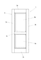
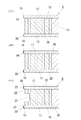
図1は、本発明にかかる框組み扉用鏡板(以下、これを単に「鏡板」と略称する)を備えた框組み扉1を示す。該框組み扉1は、左右一対の縦框2a,2bと、上下の横框3a,3bと、下方寄りの中段高さ位置に配設された中間横框3cとによって框枠体5が構成されており、該框枠体5で区画された大小二つの矩形状開口部に、該矩形状開口部を遮蔽する本発明にかかる鏡板6a,6bが装着されている。ここで、縦框2a,2bと、中間横框3cと、横框3aまたは横框3bとによって夫々囲繞される両矩形状開口部の内周縁7には、図2に示すように、凹溝8が周設されており、該凹溝8に鏡板6a,6bの外周縁に設けられた薄肉状嵌入縁部25を嵌合することにより、鏡板6a,6bが両矩形状開口部に夫々保持されている。
An embodiment of the present invention will be described below with reference to the accompanying drawings.
FIG. 1 shows a braided door 1 provided with an end plate for a braided door according to the present invention (hereinafter simply referred to as “end plate”). In the frame door 1, a
尚、この実施例では、二つの矩形状開口部を備えた框枠体5を示したが、該框枠体5は、上記中間横框3cを除去して矩形状開口部を一つにしたり、単一若しくは複数の中間縦框及び中間横框を適宜組み合わせて複数の矩形状開口部を区画形成したものとし、各矩形状開口部に鏡板を夫々装着するようにしてもよい。また、該框枠体5の露出面には後述するパネル板9及び単位枠杆11に貼着する化粧シート20と同じ化粧シートが貼着される。
In this embodiment, the
本発明にかかる上記鏡板6a,6bは、その高さ寸法が異なる以外は同一構造であり、以下に鏡板6aの構造及びその製造方法について説明する。
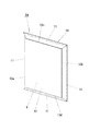
鏡板6aは、図3,図4に示すように、中央に配設された矩形状のパネル板9と、該パネル板9の四辺に組み付けられて縁取り枠10を構成する四本の単位枠杆11とからなり、組み付け状態で露出するパネル板9の露出面と、各単位枠杆11の露出面とに、組み付け前に化粧加工が施されている。また、各単位枠杆11とパネル板9は、該パネル板9の主面部12に連続する外向きの段差面13a,13b,13c,13dが鏡板6aの四周縁近傍に生じるように組み付けられている。
The above-described
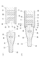
As shown in FIGS. 3 and 4, the
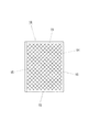
前記パネル板9は、図5に示すように、ハニカム構造の内装材14の外周に平行合板(LVL)からなる四本の枠杆15を矩形状に配設して芯材16としており、該芯材16の表裏両面に表面板17,17(図6参照)が貼着されている。ここで、パネル板9の主体材である表面板17,17には、MDF(中質繊維板),パーティクルボード,合板,集成材等の木質系基材が用いられ得るが、なかでも表面平滑性及び切削加工性に優れたMDF(中質繊維板)が最も好ましい。
As shown in FIG. 5, the
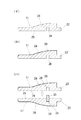
このパネル板9の製作方法は、芯材16に対する表面板17,17の貼着に際して、図6(イ)に示すように、表面板17,17の周縁を芯材16から外方に若干突出させることにより表裏一対の重ね代縁18,18を形成する。次に、後述する単位枠杆11との組み付け状態で露出することとなる露出面としての表面板17,17の表面と、該表面に略直交状に連続する上下左右の各木口面19,19とに、図6(ロ)に示すように、化粧シート20を夫々貼着して化粧加工が施される。この化粧シート20としては、突板或いは杢目模様を印刷した紙,オレフィンシート,塩ビシート等が用いられる。ここで、化粧シート20の貼着は、パネル板9の主面部12である表面板17の表面(厚み方向に向く面)と、左右の木口面19,19(横方向に向く面)と、上下の木口面19,19(縦方向に向く面)の三方向の面に対して一面毎に行われる。これにより、従来困難であった三方向の面に対する化粧シート20の貼着を、容易に効率よく低コストで行うことができる。そして、上記のように露出面に化粧シート20を貼着した後、図6(ハ)に示すように、前記芯材16の外端に外周方向に沿って嵌合溝21が周設される。尚、この時、重ね代縁18,18の内側面22,22を僅かに切削して、両内側面相互の間隔を後述する単位枠杆11の内端側厚みに一致させる間隔調整加工が施される。これにより、単位枠杆11との組み付け精度を向上させることができる。
The
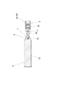
一方、各単位枠杆11は、図7(イ)に示すように、パネル板9側の内端が、前記芯材16に形成した重ね代縁18,18の内側面22,22の相互間隔と略同じ厚みに形成されており、該内端には前記芯材16の嵌合溝21に嵌合可能な嵌合突条23がその長手方向の全長に亘って突成されている。また、単位枠杆11の表裏両面には外端側に向けて先細り状に傾斜する湾曲した凸面状の面取り部24,24が形成されており、該面取り部24,24を介して薄肉となる外端に薄肉状嵌入縁部25が設けられている。ここで、各単位枠杆11の主体材には、MDF(中質繊維板),パーティクルボード,合板,集成材等の木質系基材が用いられ得るが、なかでも表面平滑性及び切削加工性に優れたMDF(中質繊維板)が最も好ましい。
On the other hand, as shown in FIG. 7 (a), each
この各単位枠杆11の製作方法としては、長尺な帯板状のMDF(中質繊維板)等からなる主体材をモルダーで切削加工することにより、図8(イ)に示すように、その上面に外端側に向けて先細り状に傾斜する湾曲した凸面状の面取り部24と、内端に表裏一対で前記嵌合突条23を構成する半割状突条部23’と、下面に長手方向に沿う雇い実矧ぎ(やといざねはぎ)用の凹溝28とを備えた半割状単位枠杆11’を形成する。この時、主体材を、下面側の平面部29を基準面として支持台上を移送させることにより、その切削加工を精度よく容易に行うことができる。次に、図8(ロ)に示すように、該半割状単位枠杆11’の上面と、その外端面及び半割状突条部23’を除く内端面とに亘って、パネル板9に貼着したものと同一の化粧シート20を一連に貼着して化粧加工を施す。この化粧シート20としては、突板或いは杢目模様を印刷した紙,オレフィンシート,塩ビシート等が用いられる。然る後、かかる半割状単位枠杆11’を表裏一対に用いて、図8(ハ)に示すように、両半割状単位枠杆11’,11’の平面部29,29相互を接着剤で張り合わせる。この時、両半割状単位枠杆11’,11’に形成された凹溝28,28内に、その溝幅に一致する木質片からなる雇い30を嵌装させることにより位置合わせ作用が得られ、両半割状単位枠杆11’,11’を精度よく表裏対称形状で接合することができる。
As a manufacturing method of each
そして、このように接合した両半割状単位枠杆11’,11’を所定長さに切断する。これにより、パネル板9との組み付け状態で露出することとなる露出面に化粧シート20を貼着してなる化粧加工と、表裏両面に湾曲した凸面状の面取り部24,24とを備えてなる各単位枠杆11が製作される。尚、各単位枠杆11の両端部は、留接ぎ構造により相互接合できるように45度の角度で切断されることとなる(図3参照)。
Then, the halved unit frame 11 ', 11' joined in this way is cut into a predetermined length. Thereby, the decorative process formed by sticking the
そして、このようにパネル板9の露出面と、各単位枠杆11の露出面とに、化粧加工を施した後、図7(ロ)に示すように、パネル板9の重ね代縁18,18を各単位枠杆11の内端側表裏面に重ね合わせた状態で、各単位枠杆11の嵌合突条23をパネル板9の嵌合溝21に嵌合して接着剤27によって接合する。これにより、パネル板9の四辺に各単位枠杆11が組み付けられて縁取り枠10(図3参照)となり、鏡板6aが完成する。ここで、パネル板9の重ね代縁18,18の端面が、パネル板9の主面部12と連続する外向きの段差面13a,13b,13c,13d(図4参照)となる。また、該重ね代縁18,18によって、各単位枠杆11の内端面と、該単位枠杆11の内端面に対向するパネル板9の芯材16の外端面との間の目地が遮蔽される。
And after giving a decorative process to the exposed surface of the
かかる構成にあって、組み付け後の鏡板6aは、図4に示すように、矩形状のパネル板9の四辺に縁取り枠10を備え、かつ、その四周縁近傍に主面部12と連続する外向きの段差面13a,13b,13c,13dが周設された複雑な形状となるため、立体感があり、意匠性に優れたものとなる。
In this configuration, the assembled
尚、図7(ロ)に示すように、各単位枠杆11の内端面と、該単位枠杆11の内端面に対向するパネル板9の芯材16の外端面との間に、組み付け時に生じるゆがみを調整する調整間隙26,26を予め設けておくことにより、該調整間隙26,26によって、単位枠杆11及びパネル板9の製作時に発生する寸法誤差に起因して組み付け時に生じる鏡板1のゆがみを調整することができ、ゆがみのない適正形状の鏡板1を得ることができる。
In addition, as shown in FIG. 7B, between the inner end surface of each
また、上記実施例では、パネル板9を構成する表面板17,17の各木口面19,19(図6(イ)参照)に化粧シート20を貼着するようにしているが、該木口面19,19の幅が極めて狭い場合には、化粧シート20の貼着に代えて塗装による化粧加工を施してもよい。これにより、木口面19,19に化粧シート20を貼着する場合に比して、美観性を殆ど損なうことなく、コストを低減することができる。
Moreover, in the said Example, although the
さらに、上記実施例では、パネル板9を構成する表面板17,17の各木口面19,19を、表面板17,17の表面に略直交させて設けているが、該木口面19,19を斜めに形成することも可能である。この場合には、パネル板9の主面部12に斜めに連続する外向きの段差面13a,13b,13c,13dを鏡板6aの四周縁近傍に生じさせることができ、略直交状に連続する段差面とは異なる意匠性を生じさせることができる。
Furthermore, in the said Example, although each
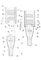
図9は、変形実施例を示し、この変形実施例は、上述した図6(ロ)に続くパネル板9の製作工程において、芯材16の外端に、重ね代縁18,18の内側面22,22に連続する所定深さの凹溝31,31を外周方向に沿って周設することにより、該重ね代縁18,18に弾性作用を付与するようにしたものである。ここで、図9(イ)に示すように、重ね代縁18,18の内側面22,22相互の間隔L1 は、単位枠杆11の内端側厚みL2 より僅かに狭く形成されている。
FIG. 9 shows a modified embodiment, which is the inner surface of the
かかる構成にあっては、単位枠杆11とパネル板9の組み付け時において、パネル板9の重ね代縁18,18間に単位枠杆11の内端を嵌入する際に、該重ね代縁18,18の内側面22,22が単位枠杆11の内端側表裏面に押圧されると、弾性作用により重ね代縁18,18が外方に開くことにより、その嵌入を容易に行うことができる。また、嵌入後においては、図9(ロ)に示すように、重ね代縁18,18の内側面22,22が単位枠杆11の内端側表裏面に、その弾性作用を介して圧接するので、隙間が生じることがない。これにより、単位枠杆11との組み付け精度をさらに向上させることができる。
In such a configuration, when the
2a,2b 縦框
3a,3b 横框
5 框枠体
6a,6b 鏡板(框組み扉用鏡板)
9 パネル板
10 縁取り枠
11 単位枠杆
12 主面部
13a,13b,13c,13d 段差面
16 芯材
17 表面板
18 重ね代縁
19 木口面
20 化粧シート(化粧加工)
21 嵌合溝
23 嵌合突条
26 調整間隙
2a,
DESCRIPTION OF
21
Claims (7)
矩形状のパネル板と、該パネル板の四辺に組み付けられる縁取り枠の単位枠杆とからなり、組み付け状態で露出する前記パネル板の露出面と、各単位枠杆の露出面とに、組み付け前に化粧加工を施したことを特徴とする框組み扉用鏡板。 In the end plate for the braided door in which the outer peripheral edge is fitted to the opening of the frame body composed of the vertical rod and the horizontal rod and shields the opening,
It consists of a rectangular panel plate and a unit frame 杆 of the rim frame that is assembled to the four sides of the panel plate, and is attached to the exposed surface of the panel plate exposed in the assembled state and the exposed surface of each unit frame 前An end panel for a framed door, characterized in that it has undergone a decorative process.
表裏両面を主面部とする矩形状のパネル板と、該パネル板の四辺に組み付けられる縁取り枠の単位枠杆とからなり、組み付け状態で露出する前記パネル板の露出面と、各単位枠杆の露出面とに、組み付け前に化粧加工を施すとともに、各単位枠杆とパネル板とを、該パネル板の主面部に連続する外向きの段差面が四周縁近傍に生じるように組み付けたことを特徴とする框組み扉用鏡板。 In the end plate for the braided door in which the outer peripheral edge is fitted to the opening of the frame body composed of the vertical rod and the horizontal rod and shields the opening,
It consists of a rectangular panel plate with the front and back both sides as the main surface part, and a unit frame 縁 of the edging frame assembled to the four sides of the panel plate, and the exposed surface of the panel plate exposed in the assembled state, Applying cosmetic treatment to the exposed surface before assembling, and assembling each unit frame ridge and panel plate so that an outward stepped surface continuous to the main surface portion of the panel plate occurs in the vicinity of the four peripheral edges. Characteristic of the end panel for the braided door.
矩形状のパネル板と、該パネル板の四辺に組み付けられる縁取り枠の単位枠杆からなり、組み付け状態で露出する前記パネル板の露出面と、各単位枠杆の露出面とに、化粧加工を施した後、パネル板の四辺に縁取り枠となる各単位枠杆を組み付けることを特徴とする框組み扉用鏡板の製造方法。
A method for manufacturing a mirror panel for a framed door in which an outer peripheral edge is fitted to an opening of a frame body composed of a vertical fence and a horizontal fence and shields the opening,
It consists of a rectangular panel plate and a unit frame の of the rim frame that is assembled to the four sides of the panel plate, and the exposed surface of the panel plate exposed in the assembled state and the exposed surface of each unit frame をA method for producing a frame plate for a framed door, wherein after the application, each unit frame frame to be an edge frame is assembled on four sides of the panel plate.
Priority Applications (1)
| Application Number | Priority Date | Filing Date | Title |
|---|---|---|---|
| JP2003305193A JP2005076216A (en) | 2003-08-28 | 2003-08-28 | End plate for door assembled from stiles and rails and its manufacturing method |
Applications Claiming Priority (1)
| Application Number | Priority Date | Filing Date | Title |
|---|---|---|---|
| JP2003305193A JP2005076216A (en) | 2003-08-28 | 2003-08-28 | End plate for door assembled from stiles and rails and its manufacturing method |
Publications (1)
| Publication Number | Publication Date |
|---|---|
| JP2005076216A true JP2005076216A (en) | 2005-03-24 |
Family
ID=34408676
Family Applications (1)
| Application Number | Title | Priority Date | Filing Date |
|---|---|---|---|
| JP2003305193A Pending JP2005076216A (en) | 2003-08-28 | 2003-08-28 | End plate for door assembled from stiles and rails and its manufacturing method |
Country Status (1)
| Country | Link |
|---|---|
| JP (1) | JP2005076216A (en) |
Cited By (1)
| Publication number | Priority date | Publication date | Assignee | Title |
|---|---|---|---|---|
| JP2016011527A (en) * | 2014-06-30 | 2016-01-21 | パナソニックIpマネジメント株式会社 | Panel material and sticking method of surface finish sheet using the same |
-
2003
- 2003-08-28 JP JP2003305193A patent/JP2005076216A/en active Pending
Cited By (1)
| Publication number | Priority date | Publication date | Assignee | Title |
|---|---|---|---|---|
| JP2016011527A (en) * | 2014-06-30 | 2016-01-21 | パナソニックIpマネジメント株式会社 | Panel material and sticking method of surface finish sheet using the same |
Similar Documents
| Publication | Publication Date | Title |
|---|---|---|
| US8539729B2 (en) | Door, method of making door, and stack of doors | |
| JP2005076216A (en) | End plate for door assembled from stiles and rails and its manufacturing method | |
| KR200439860Y1 (en) | Furniture door plate | |
| JP2013245510A (en) | Fixture and manufacturing method for the same | |
| JPH10249816A (en) | Woody furnishing material and its molding method | |
| US8561368B2 (en) | Carved solid face door and method of fabrication | |
| JPH038793Y2 (en) | ||
| JP2011246932A (en) | Framing panel | |
| JP4837511B2 (en) | Shishido and its manufacturing method | |
| JP2014095224A (en) | Framing type panel for fitting | |
| JP2010084496A (en) | Method for manufacturing lighting door | |
| JP3120063U (en) | End panel for wooden door | |
| KR200430550Y1 (en) | Furniture door plate | |
| KR200236285Y1 (en) | Door | |
| JP4020629B2 (en) | Door lattice structure | |
| JPH07233674A (en) | Frame | |
| JP4881675B2 (en) | Frame and frame mounting structure | |
| JPH0248608Y2 (en) | ||
| JPH08177330A (en) | Door having stile and rail with decorating part and having glass | |
| JPH10238095A (en) | Mounting structure for indoor fixture material | |
| JPH10238237A (en) | Door | |
| JP3041272U (en) | Structure of door frame and window frame material | |
| JPH0243990Y2 (en) | ||
| JPH0643429Y2 (en) | Opening members such as doors | |
| JP2007138621A (en) | Lighting door |