JP2005073799A - Switch controlling device - Google Patents
Switch controlling device Download PDFInfo
- Publication number
- JP2005073799A JP2005073799A JP2003305574A JP2003305574A JP2005073799A JP 2005073799 A JP2005073799 A JP 2005073799A JP 2003305574 A JP2003305574 A JP 2003305574A JP 2003305574 A JP2003305574 A JP 2003305574A JP 2005073799 A JP2005073799 A JP 2005073799A
- Authority
- JP
- Japan
- Prior art keywords
- switch
- foot switch
- image
- signal
- unit
- Prior art date
- Legal status (The legal status is an assumption and is not a legal conclusion. Google has not performed a legal analysis and makes no representation as to the accuracy of the status listed.)
- Granted
Links
- 238000003384 imaging method Methods 0.000 claims description 3
- 230000002194 synthesizing effect Effects 0.000 claims description 3
- 238000000034 method Methods 0.000 abstract description 5
- 230000008569 process Effects 0.000 abstract description 4
- 238000001356 surgical procedure Methods 0.000 abstract description 3
- 238000012790 confirmation Methods 0.000 abstract 1
- 230000006870 function Effects 0.000 description 76
- 238000010586 diagram Methods 0.000 description 19
- 230000008859 change Effects 0.000 description 4
- 230000000694 effects Effects 0.000 description 4
- 230000009471 action Effects 0.000 description 2
- 230000015271 coagulation Effects 0.000 description 1
- 238000005345 coagulation Methods 0.000 description 1
- 230000000881 depressing effect Effects 0.000 description 1
- 230000000994 depressogenic effect Effects 0.000 description 1
- 238000005286 illumination Methods 0.000 description 1
- 230000002452 interceptive effect Effects 0.000 description 1
- 238000012986 modification Methods 0.000 description 1
- 230000004048 modification Effects 0.000 description 1
- 239000007787 solid Substances 0.000 description 1
Images


Classifications
-
- A—HUMAN NECESSITIES
- A61—MEDICAL OR VETERINARY SCIENCE; HYGIENE
- A61B—DIAGNOSIS; SURGERY; IDENTIFICATION
- A61B1/00—Instruments for performing medical examinations of the interior of cavities or tubes of the body by visual or photographical inspection, e.g. endoscopes; Illuminating arrangements therefor
- A61B1/00002—Operational features of endoscopes
- A61B1/00039—Operational features of endoscopes provided with input arrangements for the user
- A61B1/00042—Operational features of endoscopes provided with input arrangements for the user for mechanical operation
-
- A—HUMAN NECESSITIES
- A61—MEDICAL OR VETERINARY SCIENCE; HYGIENE
- A61B—DIAGNOSIS; SURGERY; IDENTIFICATION
- A61B1/00—Instruments for performing medical examinations of the interior of cavities or tubes of the body by visual or photographical inspection, e.g. endoscopes; Illuminating arrangements therefor
- A61B1/00002—Operational features of endoscopes
- A61B1/00043—Operational features of endoscopes provided with output arrangements
- A61B1/00045—Display arrangement
- A61B1/0005—Display arrangement combining images e.g. side-by-side, superimposed or tiled
-
- A—HUMAN NECESSITIES
- A61—MEDICAL OR VETERINARY SCIENCE; HYGIENE
- A61B—DIAGNOSIS; SURGERY; IDENTIFICATION
- A61B17/00—Surgical instruments, devices or methods
- A61B2017/00973—Surgical instruments, devices or methods pedal-operated
-
- A—HUMAN NECESSITIES
- A61—MEDICAL OR VETERINARY SCIENCE; HYGIENE
- A61B—DIAGNOSIS; SURGERY; IDENTIFICATION
- A61B90/00—Instruments, implements or accessories specially adapted for surgery or diagnosis and not covered by any of the groups A61B1/00 - A61B50/00, e.g. for luxation treatment or for protecting wound edges
- A61B90/36—Image-producing devices or illumination devices not otherwise provided for
- A61B90/37—Surgical systems with images on a monitor during operation
Landscapes
- Life Sciences & Earth Sciences (AREA)
- Health & Medical Sciences (AREA)
- Surgery (AREA)
- Engineering & Computer Science (AREA)
- Biophysics (AREA)
- Medical Informatics (AREA)
- Nuclear Medicine, Radiotherapy & Molecular Imaging (AREA)
- Optics & Photonics (AREA)
- Pathology (AREA)
- Radiology & Medical Imaging (AREA)
- Veterinary Medicine (AREA)
- Biomedical Technology (AREA)
- Heart & Thoracic Surgery (AREA)
- Physics & Mathematics (AREA)
- Molecular Biology (AREA)
- Animal Behavior & Ethology (AREA)
- General Health & Medical Sciences (AREA)
- Public Health (AREA)
- Mechanical Engineering (AREA)
- Surgical Instruments (AREA)
- Endoscopes (AREA)
Abstract
Description
本発明は、複数の医療装置を制御するスイッチの機能を制御するスイッチ制御装置に関する。 The present invention relates to a switch control device that controls the function of a switch that controls a plurality of medical devices.
従来、例えば特開2002−306504号公報に開示されているように、1つのフットスイッチを用いて複数の外科手術装置が操作出来る外科手術システムが知られている。また、前記外科手術システムにおいて、例えば特開平11−318916号公報に開示されているようにフットスイッチの各機能ペダルに割り付けたスイッチ機能を内視鏡画像に重畳して表示する表示手段を備えた外科手術システムも知られている。 2. Description of the Related Art Conventionally, as disclosed in, for example, Japanese Patent Application Laid-Open No. 2002-306504, a surgical operation system that can operate a plurality of surgical apparatuses using a single foot switch is known. Further, the surgical operation system includes display means for displaying the switch functions assigned to the respective function pedals of the foot switch so as to be superimposed on the endoscopic image as disclosed in, for example, Japanese Patent Application Laid-Open No. 11-318916. Surgical systems are also known.
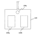
前記外科手術システムの一例を図20に示す。外科手術システム101は、ディスプレイ102、画像プロセッサ103、カメラヘッド104、光源105、超音波手術装置106、電気メス107、フットスイッチ制御装置108、フットスイッチ109で構成される。また、フットスイッチ109は、図21に示すように第1機能スイッチ109a,第2機能スイッチ109b及び選択スイッチ109cを備えて構成される。
An example of the surgical system is shown in FIG. The
超音波手術装置106及び電気メス107を制御するフットスイッチ109のフットスイッチ信号は、フットスイッチ信号制御部108bを経由して送信される。前記フットスイッチ信号制御部108bは、図21に示すフットスイッチ109の選択スイッチ109cまたは図示しない他の選択スイッチによって設定された出力機器設定に応じて切替えられ、フットスイッチ109の各ペダルの押し下げ信号を超音波手術装置106の最大出力/設定出力、電気メス107のモノポーラ/バイポーラ、切開/凝固のいずれかを示す信号を該当する機器に出力する。
The foot switch signal of the
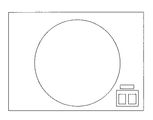
画像プロセッサ103の出力する画像信号は、フットスイッチ制御装置108の表示制御部108aを経由してディスプレイ102に入力され、内視鏡画像が表示される。前記表示制御部108aは、入力された内視鏡画像にフットスイッチ109の状態を示すフットスイッチ状態表示画像を重畳する。フットスイッチ状態表示画像は、例えば、画面の右隅に位置し、図22及び図23に示すように、フットスイッチの配列、各ペダルに対応する機能、各ペダルのオン/オフ状態を表す。フットスイッチオフの時には、図22に示すようにフットスイッチペダルは塗り潰されていない矩形で表示され、フットスイッチオンの時には、図23に示すようにペダルを示す矩形が所定の色で塗り潰し表示される。また、フットスイッチ状態の表示は、所定の色で表示されたスイッチ画像の反転・非反転によって表示することもある。
The image signal output from the
手術中にフットスイッチ状態表示画像を表示していると内視鏡画像を観察する邪魔になる場合があるため、フットスイッチ状態表示画像を表示しないことも可能である。この時、フットスイッチ109の各ペダルに割り当てられた機能は、フットスイッチ制御装置108に設けられたパネルの表示によって確認することができる。
If the foot switch state display image is displayed during surgery, it may be an obstacle to observe the endoscopic image, and therefore it is possible not to display the foot switch state display image. At this time, the function assigned to each pedal of the
さらに、例えば特開2001−314411号公報に開示されているように、単一乃至複数の外科手術装置に対して2つ以上のフットスイッチを接続し、いずれのフットスイッチによっても操作可能にした外科手術装置も知られている。
従来の医療システム制御装置においては、フットスイッチ機能表示画像は、常に内視鏡画像に重畳して表示するか、常に重畳表示しないかのどちらかであった。手術を実施するにあたって、フットスイッチ機能表示画像を表示して手術の邪魔になることを避けるため、フットスイッチ機能表示をオフにした場合は、手術中に現在選択されているフットスイッチ機能がどれか分からなくなってしまい、意図しないハンドピースから出力してしまう危険があった。この場合、フットスイッチの機能割付けを医療システム制御装置のパネルに表示するようにすれば、現在のフットスイッチ機能割付け状態の確認を随時行えるが、術者が術野から目を離して医療システム制御装置のパネルを見る必要があり、使い勝手が悪くなる。 In the conventional medical system control apparatus, the foot switch function display image is always displayed superimposed on the endoscope image or not always displayed superimposed. When performing the operation, if the foot switch function display is turned off to display the foot switch function display image and prevent it from interfering with the operation, which foot switch function is currently selected during the operation There was a danger that it would be lost and output from an unintended handpiece. In this case, if the function assignment of the foot switch is displayed on the panel of the medical system control device, the current foot switch function assignment status can be checked at any time. It is necessary to look at the panel of the device, and it becomes unusable.
また、複数のフットスイッチを接続した場合、従来は一方のフットスイッチだけを無効にすることができなかった。従って、複数のフットスイッチを接続しているものの実際には使用しないフットスイッチがある場合に、手術装置を操作していない人が誤ってフットスイッチを押して動作させてしまう可能性があった。 Further, when a plurality of foot switches are connected, conventionally only one of the foot switches cannot be disabled. Therefore, when there is a foot switch that is not actually used although a plurality of foot switches are connected, there is a possibility that a person who does not operate the surgical device will accidentally press the foot switch to operate it.
本発明は、上記事情に鑑みてなされたものであり、手術時に内視鏡画像を観察するのに邪魔にならず、且つ必要な時にフットスイッチやハンドスイッチ等のスイッチ手段に割り当てられた機能を確認することのできるスイッチ制御装置を提供することを目的としている。 The present invention has been made in view of the above circumstances, and does not interfere with observation of an endoscopic image during surgery, and has functions assigned to switch means such as a foot switch and a hand switch when necessary. An object of the present invention is to provide a switch control device that can be confirmed.
本発明のスイッチ制御装置は、被写体像を撮像する撮像装置からの画像信号を受信する画像受信部と、医療器具と前記医療器具を操作するスイッチとの割り付け状態を切り替える切替スイッチからの切替信号を受信する切替信号受信部と、前記切替信号受信部にて前記切替信号を受信した際に、前記被写体像と前記操作スイッチの情報とを重ね合わせて表示する画像信号を合成する画像合成部とを備えて構成される。 The switch control device of the present invention receives a switching signal from a switching switch that switches an allocation state between an image receiving unit that receives an image signal from an imaging device that captures a subject image and a medical device and a switch that operates the medical device. A switching signal receiving unit for receiving, and an image synthesizing unit for synthesizing an image signal to be displayed by superimposing the subject image and the information of the operation switch when the switching signal is received by the switching signal receiving unit. It is prepared for.
本発明によれば、手術時に内視鏡画像を観察するのに邪魔にならず、且つ必要な時にフットスイッチやハンドスイッチ等のスイッチ手段に割り当てられた機能を確認することができるという効果がある。 According to the present invention, there is an effect that the function assigned to the switch means such as the foot switch and the hand switch can be confirmed when necessary, without disturbing the observation of the endoscopic image during the operation. .
以下、図面を参照しながら本発明の実施例について述べる。 Embodiments of the present invention will be described below with reference to the drawings.
図1ないし図10は本発明の実施例1に係わり、図1は医療システムの構成を示す構成図、図2は図1のフットスイッチの構成を示す構成図、図3は図1のディスプレイに表示される画像を示す第1の図、図4は図1のディスプレイに表示される画像を示す第2の図、図5は図1のフットスイッチ制御装置の作用を説明する第1のフローチャート、図6は図5の処理を説明する図、図7は図1のフットスイッチ制御装置の作用を説明する第2のフローチャート、図8は図1のディスプレイに表示される画像を示す第3の図、図9は図1のフットスイッチ制御装置の作用を説明する第3のフローチャート、図10は図1のフットスイッチ制御装置の作用を説明する第4のフローチャートである。 1 to 10 relate to the first embodiment of the present invention, FIG. 1 is a configuration diagram showing the configuration of the medical system, FIG. 2 is a configuration diagram showing the configuration of the foot switch of FIG. 1, and FIG. FIG. 4 is a first diagram illustrating an image to be displayed, FIG. 4 is a second diagram illustrating an image displayed on the display of FIG. 1, and FIG. 5 is a first flowchart for explaining the operation of the foot switch control device of FIG. 6 is a diagram for explaining the processing of FIG. 5, FIG. 7 is a second flowchart for explaining the operation of the foot switch control device of FIG. 1, and FIG. 8 is a third diagram showing an image displayed on the display of FIG. 9 is a third flowchart for explaining the operation of the foot switch control device of FIG. 1, and FIG. 10 is a fourth flowchart for explaining the operation of the foot switch control device of FIG.
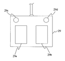
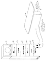
図1に示すように、本実施例の医療システム20は、ディスプレイ21、画像プロセッサ22、カメラヘッド23、光源装置24、超音波手術装置25、電気メス26、熱メス27、フットスイッチ制御装置28、フットスイッチ29を備えて構成され、光源装置24は内視鏡23aに照明光を供給しカメラヘッド23は内視鏡23aの接眼部23bに着脱自在に接続されて、内視鏡像を撮像して撮像信号を画像プロセッサ22に出力する。
As shown in FIG. 1, the
カメラヘッド23から取り込まれ画像プロセッサ22から出力された画像信号は、フットスイッチ制御装置28に入力される。更に前記画像信号はフットスイッチ制御装置28の表示制御部28aにおいて処理され、ディスプレイ21へ入力されて表示される。前記表示制御部28aでは、入力された内視鏡画像に現在割り付けられているフットスイッチ機能に対応したフットスイッチ状態を示す画像を記憶部28cから読み出して、内視鏡画像に重畳する処理を行う。
An image signal captured from the
フットスイッチ29は、図2に示すように第1機能スイッチ29a,第2機能スイッチ29b,選択スイッチ29c及びフットスイッチ状態表示トグルスイッチ29dを備えて構成される。
As shown in FIG. 2, the
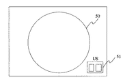
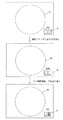
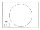
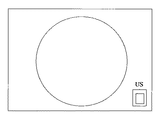
図3及び図4は内視鏡画像50の右下隅にフットスイッチ29の状態を示すフットスイッチ状態表示画像51を重畳したものである。フットスイッチ状態表示画像51の上部またはペダル上には、現在割り当てられている機能を示す表示がされている(例えば、電気メスを示す「ESU」、超音波手術装置を示す「US」等)。
3 and 4 are obtained by superimposing a foot switch
またフットスイッチ29の機能スイッチがオンされている場合、例えば第2機能スイッチ29bがオンされている場合、図4のように前記第2機能スイッチ29bに対応するフットスイッチ状態表示画像51をフットスイッチ信号オンを示す表示に変更する(矩形の塗りつぶしや、色反転等)。
When the function switch of the
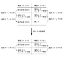
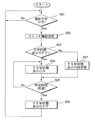
また図5のフローに従って、フットスイッチ制御装置28のフットスイッチ信号制御部28bが、術者がフットスイッチ29の選択スイッチ29cを押したことを検出する(ステップS1)と、フットスイッチ29の各ペダルに割り当てた機能を、選択スイッチ29cが押される度に図6に示すように記憶部28eに記憶された組み合わせに変更する(ステップS2)。
Further, according to the flow of FIG. 5, when the foot switch
この時、前記フットスイッチ信号制御部28bはフットスイッチの各機能スイッチ29a,29bのオン/オフ信号が超音波手術装置25、電気メス26、熱メス27のいずれに出力されるか決定するために信号接続を切替えるとともに、表示制御部28aに新しく選択された状態を通知する。前記表示制御部28aは、記憶部28dに記憶されたフットスイッチ状態表示に従って重畳するフットスイッチ状態表示画像51を生成し、新たなフットスイッチ機能に対応する表示に切替える。
At this time, the foot switch
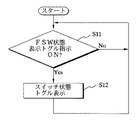
さらに、本実施例の医療システム制御装置1においては、図7に示すフローに従ってユーザが前記フットスイッチ状態表示画像の表示の有無を容易に切替えられる。例えばフットスイッチ状態表示画像51が重畳された状態で、フットスイッチ状態表示トグルスイッチ29dが押される(ステップS11)と、フットスイッチ伏態表示をオフになり(ステップS12)、図8に示すように内視鏡画像50にはフットスイッチ状態表示画像51は重畳されない状態となる。
Furthermore, in the medical
すなわち、フットスイッチ状態表示がオンの時に、フットスイッチ制御装置28のフロントパネルまたは図6に示すフットスイッチ29のフットスイッチ状態表示トグルスイッチ29dを押したことをフットスイッチ制御部28bが検出し、フットスイッチ状態表示切替信号を表示制御部28aに通知すると、表示制御部28aは図8に示すようにスイッチ状態表示をオフにする。
That is, when the foot switch state display is on, the foot
再度フットスイッチ状態表示トグルスイッチ29dを押したことが通知されると、図3に示したようにフットスイッチ状態表示をオンにする。また、フットスイッチ状態表示がオンの時にフットスイッチの第1機能スイッチ29aあるいは第2機能スイッチ29bが踏まれると、図4に示したようにフットスイッチ状態表示の該当する機能スイッチアイコンの表示を、機能スイッチオンを示す表示(反転、塗りつぶし等)に変更する。
When it is notified that the foot switch state
この場合、フットスイッチ状態表示がオフの時にフットスイッチ機能が切替えられると、ユーザは新しく割り付けられた機能を確認することができない。そのため、フットスイッチ29の第1機能スイッチ29a,第2機能スイッチ29bのいずれかが踏まれた時は、図9に示すフローに従って一時的にフットスイッチ状態表示をオンにする。
In this case, if the foot switch function is switched when the foot switch state display is off, the user cannot confirm the newly assigned function. Therefore, when either the first function switch 29a or the
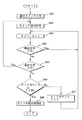
すなわち、フットスイッチ制御部28bによって選択スイッチ29cが押されたことを検知する(ステップS21)と、フットスイッチ機能を切替える(ステップS22)。現在のフットスイッチ状態表示がオフの場合(ステップS23)は表示制御部28aに通知し、フットスイッチ状態表示をオンにする(ステップS24)。更に所定の時間経過後(ステップS25)、フットスイッチ制御部28bは表示制御部28aにフットスイッチ状態表示をオフにする指示を送信する(ステップS26)。現在のフットスイッチ状態表示がオンの場合(ステップS23)は、FSW状態表示内容を更新し表示し(ステップS27)、その後ステップS25に進む。
That is, when the foot
選択スイッチ29cにより機能スイッチが切り替えられた際に、スイッチ状態を表示する(表示機能がOFFの場合は、ONに変更して表示する)。次に、一定時間経過後、スイッチ表示状態をオフにする。選択スイッチ29cにより機能が切り替えられた後に一定時間が経過した後、最初に第1機能スイッチ29a,第2機能スイッチ29bのいずれかが踏まれた場合には、機能スイッチに割りついている機能を実行せずに、スイッチ状態を表示し、次の機能スイッチが踏まれた段階で、機能スイッチに割りついている機能を実行する。
When the function switch is switched by the
また、図21に示した従来用いていたフットスイッチ109を使用する場合にも同じようにフットスイッチ状態表示を切替えることも可能である。そのフローを図10に示す。
In addition, when using the conventionally used
すなわち、フットスイッチ109の選択スイッチ109cが押されたことを検知する(ステップS31)と、フットスイッチ制御部28bはタイマを用いてカウントを開始する(ステップS32)。所定の時間t1が経過するまで選択スイッチ109cが押されていた場合(ステップS33)、所定の時間t2の間フットスイッチ状態表示を切り替える(ステップS34〜S37)。所定の時間t1が経過する前に選択スイッチ109cが離されていた場合はフットスイッチ109の各ペダルに割り当てた機能を図6に従って変更する(ステップS38)。
That is, when it is detected that the
なお、フットスイッチ29の各機能スイッチに割り付ける機能及びその切り替え順序は図6に示した組み合わせに限られない。また、前記フットスイッチ制御装置28が接続された装置を検知して対応する機器が接続されていない場合は該当するフットスイッチ機能の組み合わせ割り付けないようにすることも可能である。それ以外にも、ユーザが予めフットスイッチの各機能ペダルに割り付けるフットスイッチ機能の組み合わせを少なくとも1つ以上定義して、前記フットスイッチ制御装置28に登録して使用することも可能である。
The functions assigned to the function switches of the
本実施例によれば、医療システム制御装置を使用中にフットスイッチ状態表示を適宜オン/オフして使用することが出来る。また、フットスイッチに割り当てた機能を'随時確認出来るため、フットスイッチに状態表示をオフにしている場合もフットスイッチ機能の割り付けがわからなくなって困ることがない。 According to the present embodiment, the foot switch state display can be appropriately turned on / off during use of the medical system control device. In addition, since the function assigned to the foot switch can be confirmed at any time, even if the status display is turned off for the foot switch, the assignment of the foot switch function is not lost and there is no problem.
図11ないし図13は本発明の実施例2に係わり、図11は医療システムの構成を示す構成図、図12は図11のフットスイッチ制御装置の作用を説明するフローチャート、図13は図11のディスプレイに表示される画像を示す図である。 11 to 13 relate to the second embodiment of the present invention, FIG. 11 is a block diagram showing the configuration of the medical system, FIG. 12 is a flowchart for explaining the operation of the foot switch control device of FIG. 11, and FIG. It is a figure which shows the image displayed on a display.
実施例2は、実施例1とほとんど同じであるので、異なる点のみ説明し、同一の構成には同じ符号をつけ説明は省略する。 Since the second embodiment is almost the same as the first embodiment, only different points will be described.
本実施例のフットスイッチ制御装置28は、図11に示すように、表示制御部28a、フットスイッチ信号制御部28bの他にタイマ31c及び音声出力部31dを有する。
As shown in FIG. 11, the foot
図12に示すように、フットスイッチ29の選択スイッチ29cが踏まれる(ステップS41)と、フットスイッチ制御部28がフットスイッチ機能の割り当てを切替え(ステップS42)、表示制御部28aの出力するフットスイッチ状態表示画像51が切替わるとともに、前記タイマ31cに信号が入力され、カウントを開始する。
As shown in FIG. 12, when the
そして、所定の時間、例えば10秒が経過する前にフットスイッチ29の第1機能スイッチ29a乃至29bの入力があればタイマ31cはリセットされる(ステップS43〜S47)。タイマ31cがリセットされないまま所定の時間、例えば10秒が経過すると、図13に示すように、タイマ31cからフットスイッチ信号制御部28bに時間超過信号が出力され、フットスイッチ機能の割り当て、及びフットスイッチ状態表示が初期伏態に切替えられる(ステップS48)。
If there is an input from the
所定の時間、例えば10秒が経過してフットスイッチ機能の割付を変更した時に、フットスイッチ状態表示がオフになっている場合に実施例1と同様に所定の時間フットスイッチ状態表示をオンにした後再度オフとすることで、フットスイッチ機能の割付が変更されたことをユーザに通知してもよい。また同じ場合においてフットスイッチ機能の割付が変更されたことを音声出力部31dから音声を出力してユーザに通知してもよい。
When the foot switch function display is changed after a predetermined time, for example, 10 seconds elapses, when the foot switch state display is turned off, the foot switch state display is turned on for the predetermined time as in the first embodiment. It may be notified to the user that the assignment of the foot switch function has been changed by turning it off again later. In the same case, the
本実施例によれば、一定の時間使用しない場合はフットスイッチ機能の割付が初期状態に戻っているため、ユーザがどの状態に切替えたか思い出す必要がなくなり、操作が分かりやすくなる。 According to the present embodiment, when the switch is not used for a certain period of time, the assignment of the foot switch function returns to the initial state, so that it is not necessary for the user to remember which state is switched, and the operation becomes easy to understand.
図14は本発明の実施例3に係るフットスイッチ制御装置の構成を示す構成図である。 FIG. 14 is a configuration diagram showing the configuration of the foot switch control device according to the third embodiment of the present invention.
実施例3は、実施例2とほとんど同じであるので、異なる点のみ説明し、同一の構成には同じ符号をつけ説明は省略する。 Since the third embodiment is almost the same as the second embodiment, only different points will be described, and the same components are denoted by the same reference numerals and description thereof will be omitted.
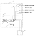
図14に示すように、本実施例のフットスイッチ制御装置28は、表示制御部61、CCPU62、記憶部63、切替部64、音声出力部65を有する。
As illustrated in FIG. 14, the foot
フットスイッチ29の機能スイッチ29a,29bが踏まれると、機能スイッチ信号がCPU62 及び切替部64に入力され、その時点のフットスイッチ機能割付に従ってフットスイッチ制御装置28に接続された超音波手術装置25もしくは電気メス26に出力される。
When the function switches 29a and 29b of the
また、フットスイッチ29の選択スイッチ29a,29bが踏まれると、CPU62 は選択スイッチ信号を検知して記憶部63に記憶されたフットスイッチ機能割付けテーブルに従って切替部64を制御し、フットスイッチ29の各機能スイッチ29a,29bに対する機能の割付を変更する。また、フットスイッチ機能の割付が変更されたことを示すフットスイッチ機能信号を表示制御部61に出力してフットスイッチ状態表示を変更する。併せて音声出力部65に音声出力指示信号を出力して、音声によりユーザにフットスイッチ機能割付が変更されたことを通知してもよい。
When the selection switches 29a and 29b of the
また、選択スイッチ信号を検知するとCPU62 はタイマ変数を初期化し、一定時間毎にカウントを行う。前記カウントが所定のカウント数に達する前に選択スイッチ信号または機能スイッチ信号が入力された場合は前記タイマ変数を初期化して再度カウントを開始する。選択スイッチ信号または機能スイッチ信号が入力されないまま所定のカウント数に遁しだ時、前記CPU62 は記憶手段53に設定された初期状態にフットスイッチ機能割付を設定するために切替部64を制御し、表示制御部61にフットスイッチ機能信号を出力する。この時、音声出力部65に音声出力指示信号を出力して、音声によりユーザにフットスイッチ機能割付が初期状態に変更されたことを通知してもよい。
When the selection switch signal is detected, the CPU 62 initializes a timer variable and counts every predetermined time. If a selection switch signal or a function switch signal is input before the count reaches a predetermined count number, the timer variable is initialized and counting is started again. When the selection count signal or function switch signal is not input and the predetermined count is reached, the CPU 62 controls the switching
本実施例によれば、実施例2と同等の効果をソフトウェアにて実現することが可能である。 According to the present embodiment, the same effect as that of the second embodiment can be realized by software.
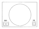
図15ないし図19は本発明の実施例4に係わり、図15は医療システムの構成を示す構成図、図16は図15のフットスイッチ制御装置の作用を説明するフローチャート、図17は図15のディスプレイに表示される画像を示す第1の図、図18は図15のディスプレイに表示される画像を示す第2の図、図19は図15のディスプレイに表示される画像を示す第3の図である。 15 to 19 relate to the fourth embodiment of the present invention, FIG. 15 is a configuration diagram showing the configuration of the medical system, FIG. 16 is a flowchart for explaining the operation of the foot switch control device of FIG. 15, and FIG. 18 is a first diagram showing an image displayed on the display, FIG. 18 is a second diagram showing an image displayed on the display of FIG. 15, and FIG. 19 is a third diagram showing an image displayed on the display of FIG. It is.
実施例4は、実施例1及び2とほとんど同じであるので、異なる点のみ説明し、同一の構成には同じ符号をつけ説明は省略する。 Since the fourth embodiment is almost the same as the first and second embodiments, only different points will be described, and the same components are denoted by the same reference numerals and description thereof will be omitted.
図15に示すように、本実施例のフットスイッチ制御装置28には、フットスイッチ71及びフットスイッチ72が接続される。
As shown in FIG. 15, a foot switch 71 and a
フットスイッチ71及びフットスイッチ72は1つ以上の機能スイッチと選択スイッチで構成され、例えば、手術台73の左右で異なる術者がそれぞれ使用できる。フットスイッチ71及びフットスイッチ72の区別はフットスイッチがIDを有してもよいし、フットスイッチ制御装置28のどのコネクタに接続されているかによって区別してもよい。
The foot switch 71 and the
図16に示すフローに従って所定の時間t3以上選択スイッチ29cを押した場合(ステップS51〜S52)、そのスイッチの有効、無効を切替える(ステップS53〜S55)。フットスイッチの有効/無効を切り替えた時は、ユーザ通知イベントとして、図17ないし図19に示すように、フットスイッチ制御装置28の表示制御部28aが内視鏡画像に重畳して出力する現在有効なフットスイッチのフットスイッチ状態表示の変更、または音声出力による通知、フットスイッチ制御装置28のパネル上の表示による通知または前記いずれかの通知方法の組み合わせによりフットスイッチの有効/無効が切り替わったことをユーザに通知する(ステップS56)。
When the
また、選択スイッチ29cを所定時間t3以下でしか押さなかった場合、フットスイッチに割り当てられてスイッチの機能の割り当て直す処理を行う(ステップS57)。
If the
無効にされているフットスイッチが踏まれた場合、フットスイッチ制御装置28はフットスイッチ信号を医療装置に出力しない。また、音声などの手段でユーザに無効なフットスイッチが踏まれたことを通知してもよい。
When a disabled foot switch is stepped on, the foot
本実施例によれば、複数のフットスイッチを用いて1人以上の術者が同時に手術を行えるだけでなく、使用していないフットスイッチは無効とすることが出来るため、誤って出力する可能性が小さくなり、装置の使い勝手が向上する。 According to the present embodiment, not only can one or more surgeons simultaneously perform operations using a plurality of foot switches, but also foot switches that are not in use can be invalidated, so there is a possibility of erroneous output. And the usability of the device is improved.
本発明は、上述した実施例に限定されるものではなく、本発明の要旨を変えない範囲において、種々の変更、改変等が可能である。 The present invention is not limited to the above-described embodiments, and various changes and modifications can be made without departing from the scope of the present invention.
20…医療システム
21…ディスプレイ
22…画像プロセッサ22
23…カメラヘッド
24…光源装置
25…超音波手術装置
26…電気メス
27…熱メス
28…フットスイッチ制御装置
28a…表示制御部
28b…フットスイッチ信号制御部
28c、28d、28e…記憶部
29…フットスイッチ
29a…第1機能スイッチ
29b…第2機能スイッチ
29c…選択スイッチ
29d…フットスイッチ状態表示トグルスイッチ
代理人 弁理士 伊藤 進
20 ...
23 ...
Claims (5)
医療器具と前記医療器具を操作するスイッチとの割り付け状態を切り替える切替スイッチからの切替信号を受信する切替信号受信部と、
前記切替信号受信部にて前記切替信号を受信した際に、前記被写体像と前記操作スイッチの情報とを重ね合わせて表示する画像信号を合成する画像合成部と
を備えたことを特徴とするスイッチ制御装置。 An image receiving unit that receives an image signal from an imaging device that captures a subject image;
A switching signal receiving unit that receives a switching signal from a switching switch that switches an allocation state between a medical instrument and a switch that operates the medical instrument;
An image composition unit configured to compose an image signal for superimposing and displaying the subject image and the information of the operation switch when the switching signal is received by the switching signal reception unit; Control device.
前記切替信号を受信した後に、経過時間の計測を開始する経過時間計測部と、
前記経過時間が所定の時間内に、前記操作スイッチからの操作信号を受信したかどうかを判定する経過時間判定部と、
前記経過時間判定部において所定の時間が経過した場合に、前記操作スイッチの割り付けを所定の状態に戻す操作割付解除部と
を有することを特徴とする請求項1に記載のスイッチ制御装置。 An operation assigning unit that assigns a medical instrument to be operated to the operation switch by the switching signal;
An elapsed time measuring unit that starts measuring elapsed time after receiving the switching signal;
An elapsed time determination unit that determines whether or not an operation signal from the operation switch has been received within a predetermined time; and
The switch control device according to claim 1, further comprising: an operation allocation canceling unit that returns the operation switch allocation to a predetermined state when a predetermined time elapses in the elapsed time determination unit.
を有することを特徴とする請求項1または2に記載のスイッチ制御装置。 The switch control device according to claim 1, further comprising: a composition canceling unit that receives the switching signal and cancels the composition processing of the image composition unit after a predetermined time has elapsed.
前記切替信号を受信した後に、経過時間の計測を開始する経過時間計測部と、
前記経過時間が所定の時間内に、前記操作スイッチからの操作信号を受信したかどうかを判定する経過時間判定部と、
前記経過時間判定部において所定の時間が経過し、且つ前記操作スイッチより操作信号を受信した際に、前記被写体像と前記操作スイッチの情報とを重ね合わせて表示する画像信号を再合成する再合成部と
を有することを特徴とする請求項1に記載のスイッチ制御装置。 An operation assigning unit that assigns a medical instrument to be operated to the operation switch by the switching signal;
An elapsed time measuring unit that starts measuring elapsed time after receiving the switching signal;
An elapsed time determination unit that determines whether or not an operation signal from the operation switch has been received within a predetermined time; and
Resynthesizing to re-synthesize an image signal to be displayed by superimposing the subject image and the information of the operation switch when a predetermined time has elapsed in the elapsed time determination unit and an operation signal is received from the operation switch The switch control device according to claim 1, further comprising:
前記合成手段もしくは再合成手段は、無効が設定された操作スイッチより操作信号を受信した際に、前記被写体像と前記操作スイッチが無効であることを示す情報を重ね合わせて表示する画像信号を合成する
ことを特徴とする請求項1または4に記載のスイッチ制御装置。 The switching signal includes information for switching between valid and invalid operation switches,
The synthesizing unit or the re-synthesizing unit synthesizes an image signal to be displayed by superimposing the subject image and information indicating that the operation switch is invalid when an operation signal is received from the operation switch set to invalid. The switch control device according to claim 1 or 4, wherein:
Priority Applications (2)
| Application Number | Priority Date | Filing Date | Title |
|---|---|---|---|
| JP2003305574A JP4217134B2 (en) | 2003-08-28 | 2003-08-28 | Switch control device |
| US10/925,109 US7488285B2 (en) | 2003-08-28 | 2004-08-24 | Switch control apparatus for controlling functions of a switch by displaying information relating to the switch controlling a plurality of medical devices |
Applications Claiming Priority (1)
| Application Number | Priority Date | Filing Date | Title |
|---|---|---|---|
| JP2003305574A JP4217134B2 (en) | 2003-08-28 | 2003-08-28 | Switch control device |
Publications (2)
| Publication Number | Publication Date |
|---|---|
| JP2005073799A true JP2005073799A (en) | 2005-03-24 |
| JP4217134B2 JP4217134B2 (en) | 2009-01-28 |
Family
ID=34214061
Family Applications (1)
| Application Number | Title | Priority Date | Filing Date |
|---|---|---|---|
| JP2003305574A Expired - Fee Related JP4217134B2 (en) | 2003-08-28 | 2003-08-28 | Switch control device |
Country Status (2)
| Country | Link |
|---|---|
| US (1) | US7488285B2 (en) |
| JP (1) | JP4217134B2 (en) |
Cited By (5)
| Publication number | Priority date | Publication date | Assignee | Title |
|---|---|---|---|---|
| JP2007068559A (en) * | 2005-09-02 | 2007-03-22 | Olympus Medical Systems Corp | System operating device and operating room control system |
| JP2012183346A (en) * | 2005-03-31 | 2012-09-27 | Alcon Inc | Irradiation method of surgical laser using surgical footswitch |
| JP2014200547A (en) * | 2013-04-08 | 2014-10-27 | 学校法人同志社 | Endoscope system |
| US12082769B2 (en) | 2018-08-17 | 2024-09-10 | Fujifilm Corporation | Endoscope system |
| US12232690B2 (en) | 2018-08-17 | 2025-02-25 | Fujifilm Corporation | Endoscope system |
Families Citing this family (152)
| Publication number | Priority date | Publication date | Assignee | Title |
|---|---|---|---|---|
| US11229472B2 (en) | 2001-06-12 | 2022-01-25 | Cilag Gmbh International | Modular battery powered handheld surgical instrument with multiple magnetic position sensors |
| US7883458B2 (en) * | 2003-06-27 | 2011-02-08 | Stryker Corporation | System for remotely controlling two or more medical devices |
| US9035741B2 (en) | 2003-06-27 | 2015-05-19 | Stryker Corporation | Foot-operated control console for wirelessly controlling medical devices |
| JP2005058616A (en) * | 2003-08-19 | 2005-03-10 | Olympus Corp | Control device for medical system and method of control for medical system |
| US8182501B2 (en) | 2004-02-27 | 2012-05-22 | Ethicon Endo-Surgery, Inc. | Ultrasonic surgical shears and method for sealing a blood vessel using same |
| EP3162309B1 (en) | 2004-10-08 | 2022-10-26 | Ethicon LLC | Ultrasonic surgical instrument |
| WO2006050410A1 (en) * | 2004-11-01 | 2006-05-11 | Stryker Corporation | Secure transmission of wireless control to central unit |
| JP2006271697A (en) * | 2005-03-29 | 2006-10-12 | Fujinon Corp | Electronic endoscope |
| US20070191713A1 (en) | 2005-10-14 | 2007-08-16 | Eichmann Stephen E | Ultrasonic device for cutting and coagulating |
| US20070166662A1 (en) * | 2006-01-17 | 2007-07-19 | Kevin Lint | Hard-wired and wireless system with footswitch for operating a dental or medical treatment apparatus |
| US7621930B2 (en) | 2006-01-20 | 2009-11-24 | Ethicon Endo-Surgery, Inc. | Ultrasound medical instrument having a medical ultrasonic blade |
| US20080234709A1 (en) | 2007-03-22 | 2008-09-25 | Houser Kevin L | Ultrasonic surgical instrument and cartilage and bone shaping blades therefor |
| US8057498B2 (en) | 2007-11-30 | 2011-11-15 | Ethicon Endo-Surgery, Inc. | Ultrasonic surgical instrument blades |
| US8911460B2 (en) | 2007-03-22 | 2014-12-16 | Ethicon Endo-Surgery, Inc. | Ultrasonic surgical instruments |
| US8226675B2 (en) | 2007-03-22 | 2012-07-24 | Ethicon Endo-Surgery, Inc. | Surgical instruments |
| US8142461B2 (en) | 2007-03-22 | 2012-03-27 | Ethicon Endo-Surgery, Inc. | Surgical instruments |
| US8808319B2 (en) | 2007-07-27 | 2014-08-19 | Ethicon Endo-Surgery, Inc. | Surgical instruments |
| US8882791B2 (en) | 2007-07-27 | 2014-11-11 | Ethicon Endo-Surgery, Inc. | Ultrasonic surgical instruments |
| US8523889B2 (en) | 2007-07-27 | 2013-09-03 | Ethicon Endo-Surgery, Inc. | Ultrasonic end effectors with increased active length |
| US8430898B2 (en) | 2007-07-31 | 2013-04-30 | Ethicon Endo-Surgery, Inc. | Ultrasonic surgical instruments |
| US8512365B2 (en) | 2007-07-31 | 2013-08-20 | Ethicon Endo-Surgery, Inc. | Surgical instruments |
| US9044261B2 (en) | 2007-07-31 | 2015-06-02 | Ethicon Endo-Surgery, Inc. | Temperature controlled ultrasonic surgical instruments |
| AU2008308606B2 (en) * | 2007-10-05 | 2014-12-18 | Ethicon Endo-Surgery, Inc. | Ergonomic surgical instruments |
| US8149108B2 (en) * | 2007-11-14 | 2012-04-03 | Stryker Corporation | System and method for automatically powering on and synchronizing a wireless remote console to a central control unit so as to allow remote control of a medical device |
| US10010339B2 (en) | 2007-11-30 | 2018-07-03 | Ethicon Llc | Ultrasonic surgical blades |
| JP5426834B2 (en) * | 2008-03-27 | 2014-02-26 | オリンパスメディカルシステムズ株式会社 | Endoscopic imaging device |
| US9089360B2 (en) | 2008-08-06 | 2015-07-28 | Ethicon Endo-Surgery, Inc. | Devices and techniques for cutting and coagulating tissue |
| US8058771B2 (en) | 2008-08-06 | 2011-11-15 | Ethicon Endo-Surgery, Inc. | Ultrasonic device for cutting and coagulating with stepped output |
| US9700339B2 (en) | 2009-05-20 | 2017-07-11 | Ethicon Endo-Surgery, Inc. | Coupling arrangements and methods for attaching tools to ultrasonic surgical instruments |
| US8334635B2 (en) | 2009-06-24 | 2012-12-18 | Ethicon Endo-Surgery, Inc. | Transducer arrangements for ultrasonic surgical instruments |
| US9017326B2 (en) * | 2009-07-15 | 2015-04-28 | Ethicon Endo-Surgery, Inc. | Impedance monitoring apparatus, system, and method for ultrasonic surgical instruments |
| US8461744B2 (en) | 2009-07-15 | 2013-06-11 | Ethicon Endo-Surgery, Inc. | Rotating transducer mount for ultrasonic surgical instruments |
| US8663220B2 (en) | 2009-07-15 | 2014-03-04 | Ethicon Endo-Surgery, Inc. | Ultrasonic surgical instruments |
| USRE47996E1 (en) | 2009-10-09 | 2020-05-19 | Ethicon Llc | Surgical generator for ultrasonic and electrosurgical devices |
| US11090104B2 (en) | 2009-10-09 | 2021-08-17 | Cilag Gmbh International | Surgical generator for ultrasonic and electrosurgical devices |
| US10441345B2 (en) * | 2009-10-09 | 2019-10-15 | Ethicon Llc | Surgical generator for ultrasonic and electrosurgical devices |
| US9039695B2 (en) | 2009-10-09 | 2015-05-26 | Ethicon Endo-Surgery, Inc. | Surgical generator for ultrasonic and electrosurgical devices |
| US9168054B2 (en) | 2009-10-09 | 2015-10-27 | Ethicon Endo-Surgery, Inc. | Surgical generator for ultrasonic and electrosurgical devices |
| US8531064B2 (en) * | 2010-02-11 | 2013-09-10 | Ethicon Endo-Surgery, Inc. | Ultrasonically powered surgical instruments with rotating cutting implement |
| US8469981B2 (en) | 2010-02-11 | 2013-06-25 | Ethicon Endo-Surgery, Inc. | Rotatable cutting implement arrangements for ultrasonic surgical instruments |
| US8579928B2 (en) | 2010-02-11 | 2013-11-12 | Ethicon Endo-Surgery, Inc. | Outer sheath and blade arrangements for ultrasonic surgical instruments |
| US8961547B2 (en) | 2010-02-11 | 2015-02-24 | Ethicon Endo-Surgery, Inc. | Ultrasonic surgical instruments with moving cutting implement |
| US8951272B2 (en) * | 2010-02-11 | 2015-02-10 | Ethicon Endo-Surgery, Inc. | Seal arrangements for ultrasonically powered surgical instruments |
| US8486096B2 (en) | 2010-02-11 | 2013-07-16 | Ethicon Endo-Surgery, Inc. | Dual purpose surgical instrument for cutting and coagulating tissue |
| GB2480498A (en) | 2010-05-21 | 2011-11-23 | Ethicon Endo Surgery Inc | Medical device comprising RF circuitry |
| US8795327B2 (en) | 2010-07-22 | 2014-08-05 | Ethicon Endo-Surgery, Inc. | Electrosurgical instrument with separate closure and cutting members |
| US9192431B2 (en) | 2010-07-23 | 2015-11-24 | Ethicon Endo-Surgery, Inc. | Electrosurgical cutting and sealing instrument |
| US9259265B2 (en) | 2011-07-22 | 2016-02-16 | Ethicon Endo-Surgery, Llc | Surgical instruments for tensioning tissue |
| JP6165780B2 (en) | 2012-02-10 | 2017-07-19 | エシコン・エンド−サージェリィ・インコーポレイテッドEthicon Endo−Surgery,Inc. | Robot-controlled surgical instrument |
| US9241731B2 (en) | 2012-04-09 | 2016-01-26 | Ethicon Endo-Surgery, Inc. | Rotatable electrical connection for ultrasonic surgical instruments |
| US9439668B2 (en) | 2012-04-09 | 2016-09-13 | Ethicon Endo-Surgery, Llc | Switch arrangements for ultrasonic surgical instruments |
| US9226766B2 (en) | 2012-04-09 | 2016-01-05 | Ethicon Endo-Surgery, Inc. | Serial communication protocol for medical device |
| US9724118B2 (en) | 2012-04-09 | 2017-08-08 | Ethicon Endo-Surgery, Llc | Techniques for cutting and coagulating tissue for ultrasonic surgical instruments |
| US9237921B2 (en) | 2012-04-09 | 2016-01-19 | Ethicon Endo-Surgery, Inc. | Devices and techniques for cutting and coagulating tissue |
| US20140005705A1 (en) | 2012-06-29 | 2014-01-02 | Ethicon Endo-Surgery, Inc. | Surgical instruments with articulating shafts |
| US9326788B2 (en) | 2012-06-29 | 2016-05-03 | Ethicon Endo-Surgery, Llc | Lockout mechanism for use with robotic electrosurgical device |
| US9408622B2 (en) | 2012-06-29 | 2016-08-09 | Ethicon Endo-Surgery, Llc | Surgical instruments with articulating shafts |
| US9351754B2 (en) | 2012-06-29 | 2016-05-31 | Ethicon Endo-Surgery, Llc | Ultrasonic surgical instruments with distally positioned jaw assemblies |
| US9820768B2 (en) | 2012-06-29 | 2017-11-21 | Ethicon Llc | Ultrasonic surgical instruments with control mechanisms |
| US9393037B2 (en) | 2012-06-29 | 2016-07-19 | Ethicon Endo-Surgery, Llc | Surgical instruments with articulating shafts |
| US9283045B2 (en) | 2012-06-29 | 2016-03-15 | Ethicon Endo-Surgery, Llc | Surgical instruments with fluid management system |
| US9226767B2 (en) | 2012-06-29 | 2016-01-05 | Ethicon Endo-Surgery, Inc. | Closed feedback control for electrosurgical device |
| US20140005702A1 (en) | 2012-06-29 | 2014-01-02 | Ethicon Endo-Surgery, Inc. | Ultrasonic surgical instruments with distally positioned transducers |
| US9198714B2 (en) | 2012-06-29 | 2015-12-01 | Ethicon Endo-Surgery, Inc. | Haptic feedback devices for surgical robot |
| WO2014052181A1 (en) | 2012-09-28 | 2014-04-03 | Ethicon Endo-Surgery, Inc. | Multi-function bi-polar forceps |
| US10201365B2 (en) | 2012-10-22 | 2019-02-12 | Ethicon Llc | Surgeon feedback sensing and display methods |
| US9095367B2 (en) | 2012-10-22 | 2015-08-04 | Ethicon Endo-Surgery, Inc. | Flexible harmonic waveguides/blades for surgical instruments |
| US20140135804A1 (en) | 2012-11-15 | 2014-05-15 | Ethicon Endo-Surgery, Inc. | Ultrasonic and electrosurgical devices |
| US10226273B2 (en) | 2013-03-14 | 2019-03-12 | Ethicon Llc | Mechanical fasteners for use with surgical energy devices |
| US9241728B2 (en) | 2013-03-15 | 2016-01-26 | Ethicon Endo-Surgery, Inc. | Surgical instrument with multiple clamping mechanisms |
| US9498194B2 (en) * | 2013-04-17 | 2016-11-22 | University Of Washington | Surgical instrument input device organization systems and associated methods |
| US9814514B2 (en) | 2013-09-13 | 2017-11-14 | Ethicon Llc | Electrosurgical (RF) medical instruments for cutting and coagulating tissue |
| US9265926B2 (en) | 2013-11-08 | 2016-02-23 | Ethicon Endo-Surgery, Llc | Electrosurgical devices |
| GB2521228A (en) | 2013-12-16 | 2015-06-17 | Ethicon Endo Surgery Inc | Medical device |
| GB2521229A (en) | 2013-12-16 | 2015-06-17 | Ethicon Endo Surgery Inc | Medical device |
| US9795436B2 (en) | 2014-01-07 | 2017-10-24 | Ethicon Llc | Harvesting energy from a surgical generator |
| US9554854B2 (en) | 2014-03-18 | 2017-01-31 | Ethicon Endo-Surgery, Llc | Detecting short circuits in electrosurgical medical devices |
| US10092310B2 (en) | 2014-03-27 | 2018-10-09 | Ethicon Llc | Electrosurgical devices |
| US10463421B2 (en) | 2014-03-27 | 2019-11-05 | Ethicon Llc | Two stage trigger, clamp and cut bipolar vessel sealer |
| US9737355B2 (en) | 2014-03-31 | 2017-08-22 | Ethicon Llc | Controlling impedance rise in electrosurgical medical devices |
| US9913680B2 (en) | 2014-04-15 | 2018-03-13 | Ethicon Llc | Software algorithms for electrosurgical instruments |
| US10285724B2 (en) | 2014-07-31 | 2019-05-14 | Ethicon Llc | Actuation mechanisms and load adjustment assemblies for surgical instruments |
| US10639092B2 (en) | 2014-12-08 | 2020-05-05 | Ethicon Llc | Electrode configurations for surgical instruments |
| US10245095B2 (en) | 2015-02-06 | 2019-04-02 | Ethicon Llc | Electrosurgical instrument with rotation and articulation mechanisms |
| US10321950B2 (en) | 2015-03-17 | 2019-06-18 | Ethicon Llc | Managing tissue treatment |
| US10342602B2 (en) | 2015-03-17 | 2019-07-09 | Ethicon Llc | Managing tissue treatment |
| US10595929B2 (en) | 2015-03-24 | 2020-03-24 | Ethicon Llc | Surgical instruments with firing system overload protection mechanisms |
| US10034684B2 (en) | 2015-06-15 | 2018-07-31 | Ethicon Llc | Apparatus and method for dissecting and coagulating tissue |
| US11020140B2 (en) | 2015-06-17 | 2021-06-01 | Cilag Gmbh International | Ultrasonic surgical blade for use with ultrasonic surgical instruments |
| US10898256B2 (en) | 2015-06-30 | 2021-01-26 | Ethicon Llc | Surgical system with user adaptable techniques based on tissue impedance |
| US10357303B2 (en) | 2015-06-30 | 2019-07-23 | Ethicon Llc | Translatable outer tube for sealing using shielded lap chole dissector |
| US10765470B2 (en) | 2015-06-30 | 2020-09-08 | Ethicon Llc | Surgical system with user adaptable techniques employing simultaneous energy modalities based on tissue parameters |
| US11129669B2 (en) | 2015-06-30 | 2021-09-28 | Cilag Gmbh International | Surgical system with user adaptable techniques based on tissue type |
| US10034704B2 (en) | 2015-06-30 | 2018-07-31 | Ethicon Llc | Surgical instrument with user adaptable algorithms |
| US11051873B2 (en) | 2015-06-30 | 2021-07-06 | Cilag Gmbh International | Surgical system with user adaptable techniques employing multiple energy modalities based on tissue parameters |
| US10154852B2 (en) | 2015-07-01 | 2018-12-18 | Ethicon Llc | Ultrasonic surgical blade with improved cutting and coagulation features |
| US10687884B2 (en) | 2015-09-30 | 2020-06-23 | Ethicon Llc | Circuits for supplying isolated direct current (DC) voltage to surgical instruments |
| US10595930B2 (en) | 2015-10-16 | 2020-03-24 | Ethicon Llc | Electrode wiping surgical device |
| US10179022B2 (en) | 2015-12-30 | 2019-01-15 | Ethicon Llc | Jaw position impedance limiter for electrosurgical instrument |
| US10575892B2 (en) | 2015-12-31 | 2020-03-03 | Ethicon Llc | Adapter for electrical surgical instruments |
| US11229471B2 (en) | 2016-01-15 | 2022-01-25 | Cilag Gmbh International | Modular battery powered handheld surgical instrument with selective application of energy based on tissue characterization |
| US11129670B2 (en) | 2016-01-15 | 2021-09-28 | Cilag Gmbh International | Modular battery powered handheld surgical instrument with selective application of energy based on button displacement, intensity, or local tissue characterization |
| US10716615B2 (en) | 2016-01-15 | 2020-07-21 | Ethicon Llc | Modular battery powered handheld surgical instrument with curved end effectors having asymmetric engagement between jaw and blade |
| US12193698B2 (en) | 2016-01-15 | 2025-01-14 | Cilag Gmbh International | Method for self-diagnosing operation of a control switch in a surgical instrument system |
| US11058448B2 (en) | 2016-01-15 | 2021-07-13 | Cilag Gmbh International | Modular battery powered handheld surgical instrument with multistage generator circuits |
| US10555769B2 (en) | 2016-02-22 | 2020-02-11 | Ethicon Llc | Flexible circuits for electrosurgical instrument |
| US10646269B2 (en) | 2016-04-29 | 2020-05-12 | Ethicon Llc | Non-linear jaw gap for electrosurgical instruments |
| US10485607B2 (en) | 2016-04-29 | 2019-11-26 | Ethicon Llc | Jaw structure with distal closure for electrosurgical instruments |
| US10702329B2 (en) | 2016-04-29 | 2020-07-07 | Ethicon Llc | Jaw structure with distal post for electrosurgical instruments |
| US10456193B2 (en) | 2016-05-03 | 2019-10-29 | Ethicon Llc | Medical device with a bilateral jaw configuration for nerve stimulation |
| CN105877836A (en) * | 2016-05-27 | 2016-08-24 | 厚凯(北京)医疗科技有限公司 | Surgery energy platform system |
| US10245064B2 (en) | 2016-07-12 | 2019-04-02 | Ethicon Llc | Ultrasonic surgical instrument with piezoelectric central lumen transducer |
| US10893883B2 (en) | 2016-07-13 | 2021-01-19 | Ethicon Llc | Ultrasonic assembly for use with ultrasonic surgical instruments |
| US10842522B2 (en) | 2016-07-15 | 2020-11-24 | Ethicon Llc | Ultrasonic surgical instruments having offset blades |
| US10376305B2 (en) | 2016-08-05 | 2019-08-13 | Ethicon Llc | Methods and systems for advanced harmonic energy |
| US10285723B2 (en) | 2016-08-09 | 2019-05-14 | Ethicon Llc | Ultrasonic surgical blade with improved heel portion |
| USD847990S1 (en) | 2016-08-16 | 2019-05-07 | Ethicon Llc | Surgical instrument |
| US10952759B2 (en) | 2016-08-25 | 2021-03-23 | Ethicon Llc | Tissue loading of a surgical instrument |
| US10736649B2 (en) | 2016-08-25 | 2020-08-11 | Ethicon Llc | Electrical and thermal connections for ultrasonic transducer |
| US10603064B2 (en) | 2016-11-28 | 2020-03-31 | Ethicon Llc | Ultrasonic transducer |
| US11266430B2 (en) | 2016-11-29 | 2022-03-08 | Cilag Gmbh International | End effector control and calibration |
| DE102017113393A1 (en) * | 2017-06-19 | 2018-12-20 | Fresenius Medical Care Deutschland Gmbh | Control device for blood treatment device and blood treatment device |
| US10820920B2 (en) | 2017-07-05 | 2020-11-03 | Ethicon Llc | Reusable ultrasonic medical devices and methods of their use |
| CN107374568B (en) * | 2017-09-12 | 2019-06-14 | 青岛市妇女儿童医院 | An intelligent integrated obstetrics and gynecology medical examination device |
| EP3873351B1 (en) | 2018-10-29 | 2023-09-20 | Stryker Corporation | System of performing spine surgery and maintaining a volume of fluid at a surgical site |
| JP7080861B2 (en) * | 2019-07-29 | 2022-06-06 | 株式会社メディカロイド | Surgical system |
| US11986234B2 (en) | 2019-12-30 | 2024-05-21 | Cilag Gmbh International | Surgical system communication pathways |
| US12064109B2 (en) | 2019-12-30 | 2024-08-20 | Cilag Gmbh International | Surgical instrument comprising a feedback control circuit |
| US12336747B2 (en) | 2019-12-30 | 2025-06-24 | Cilag Gmbh International | Method of operating a combination ultrasonic / bipolar RF surgical device with a combination energy modality end-effector |
| US11937863B2 (en) | 2019-12-30 | 2024-03-26 | Cilag Gmbh International | Deflectable electrode with variable compression bias along the length of the deflectable electrode |
| US11812957B2 (en) | 2019-12-30 | 2023-11-14 | Cilag Gmbh International | Surgical instrument comprising a signal interference resolution system |
| US11723716B2 (en) | 2019-12-30 | 2023-08-15 | Cilag Gmbh International | Electrosurgical instrument with variable control mechanisms |
| US12343063B2 (en) | 2019-12-30 | 2025-07-01 | Cilag Gmbh International | Multi-layer clamp arm pad for enhanced versatility and performance of a surgical device |
| US11944366B2 (en) | 2019-12-30 | 2024-04-02 | Cilag Gmbh International | Asymmetric segmented ultrasonic support pad for cooperative engagement with a movable RF electrode |
| US12082808B2 (en) | 2019-12-30 | 2024-09-10 | Cilag Gmbh International | Surgical instrument comprising a control system responsive to software configurations |
| US12053224B2 (en) | 2019-12-30 | 2024-08-06 | Cilag Gmbh International | Variation in electrode parameters and deflectable electrode to modify energy density and tissue interaction |
| US12023086B2 (en) | 2019-12-30 | 2024-07-02 | Cilag Gmbh International | Electrosurgical instrument for delivering blended energy modalities to tissue |
| US11779387B2 (en) | 2019-12-30 | 2023-10-10 | Cilag Gmbh International | Clamp arm jaw to minimize tissue sticking and improve tissue control |
| US11950797B2 (en) | 2019-12-30 | 2024-04-09 | Cilag Gmbh International | Deflectable electrode with higher distal bias relative to proximal bias |
| US12114912B2 (en) | 2019-12-30 | 2024-10-15 | Cilag Gmbh International | Non-biased deflectable electrode to minimize contact between ultrasonic blade and electrode |
| US11696776B2 (en) | 2019-12-30 | 2023-07-11 | Cilag Gmbh International | Articulatable surgical instrument |
| US11786291B2 (en) | 2019-12-30 | 2023-10-17 | Cilag Gmbh International | Deflectable support of RF energy electrode with respect to opposing ultrasonic blade |
| US11986201B2 (en) | 2019-12-30 | 2024-05-21 | Cilag Gmbh International | Method for operating a surgical instrument |
| US12349961B2 (en) | 2019-12-30 | 2025-07-08 | Cilag Gmbh International | Electrosurgical instrument with electrodes operable in bipolar and monopolar modes |
| US11452525B2 (en) | 2019-12-30 | 2022-09-27 | Cilag Gmbh International | Surgical instrument comprising an adjustment system |
| US11660089B2 (en) | 2019-12-30 | 2023-05-30 | Cilag Gmbh International | Surgical instrument comprising a sensing system |
| US12076006B2 (en) | 2019-12-30 | 2024-09-03 | Cilag Gmbh International | Surgical instrument comprising an orientation detection system |
| US11911063B2 (en) | 2019-12-30 | 2024-02-27 | Cilag Gmbh International | Techniques for detecting ultrasonic blade to electrode contact and reducing power to ultrasonic blade |
| US20210196361A1 (en) | 2019-12-30 | 2021-07-01 | Ethicon Llc | Electrosurgical instrument with monopolar and bipolar energy capabilities |
| US11779329B2 (en) | 2019-12-30 | 2023-10-10 | Cilag Gmbh International | Surgical instrument comprising a flex circuit including a sensor system |
| US11707318B2 (en) | 2019-12-30 | 2023-07-25 | Cilag Gmbh International | Surgical instrument with jaw alignment features |
| US12262937B2 (en) | 2019-12-30 | 2025-04-01 | Cilag Gmbh International | User interface for surgical instrument with combination energy modality end-effector |
Family Cites Families (17)
| Publication number | Priority date | Publication date | Assignee | Title |
|---|---|---|---|---|
| JPS62266024A (en) * | 1986-05-14 | 1987-11-18 | オリンパス光学工業株式会社 | Endoscope video system |
| US4854301A (en) * | 1986-11-13 | 1989-08-08 | Olympus Optical Co., Ltd. | Endoscope apparatus having a chair with a switch |
| JPH0698120B2 (en) * | 1987-03-23 | 1994-12-07 | オリンパス光学工業株式会社 | Video scope system |
| US5259365A (en) * | 1989-07-26 | 1993-11-09 | Olympus Optical Co., Ltd. | Endoscope examination apparatus |
| US5627584A (en) * | 1991-01-17 | 1997-05-06 | Olympus Optical Co., Ltd. | Endoscope system with centralized control of associated peripheral equipment |
| US6646541B1 (en) * | 1996-06-24 | 2003-11-11 | Computer Motion, Inc. | General purpose distributed operating room control system |
| US5877802A (en) * | 1996-05-21 | 1999-03-02 | Asahi Kogaku Kogyo Kabushiki Kaisha | Video-signal processing device connectable to an electronic endoscope |
| JP3245348B2 (en) | 1996-06-05 | 2002-01-15 | 富士重工業株式会社 | Vehicle failure diagnosis device |
| US5847759A (en) * | 1997-01-03 | 1998-12-08 | Williams; Ronald R. | Combination electronic iris and connector for use with a light source |
| JP4297525B2 (en) | 1998-05-18 | 2009-07-15 | オリンパス株式会社 | Medical system controller |
| JP3514979B2 (en) * | 1998-08-06 | 2004-04-05 | オリンパス株式会社 | Endoscope device |
| US6348035B1 (en) * | 1998-09-09 | 2002-02-19 | Asahi Kogaku Kogyo Kabushiki Kaisha | Connection system for electronic endoscope |
| JP2001095747A (en) * | 1999-09-30 | 2001-04-10 | Olympus Optical Co Ltd | Electronic endoscope |
| JP4391706B2 (en) | 2000-02-29 | 2009-12-24 | オリンパス株式会社 | Surgical system |
| JP4827284B2 (en) | 2000-08-18 | 2011-11-30 | Hoya株式会社 | Endoscope device |
| JP2002238919A (en) | 2001-02-20 | 2002-08-27 | Olympus Optical Co Ltd | Control apparatus for medical care system and medical care system |
| JP2002306504A (en) | 2001-04-18 | 2002-10-22 | Olympus Optical Co Ltd | Surgical system |
-
2003
- 2003-08-28 JP JP2003305574A patent/JP4217134B2/en not_active Expired - Fee Related
-
2004
- 2004-08-24 US US10/925,109 patent/US7488285B2/en not_active Expired - Lifetime
Cited By (5)
| Publication number | Priority date | Publication date | Assignee | Title |
|---|---|---|---|---|
| JP2012183346A (en) * | 2005-03-31 | 2012-09-27 | Alcon Inc | Irradiation method of surgical laser using surgical footswitch |
| JP2007068559A (en) * | 2005-09-02 | 2007-03-22 | Olympus Medical Systems Corp | System operating device and operating room control system |
| JP2014200547A (en) * | 2013-04-08 | 2014-10-27 | 学校法人同志社 | Endoscope system |
| US12082769B2 (en) | 2018-08-17 | 2024-09-10 | Fujifilm Corporation | Endoscope system |
| US12232690B2 (en) | 2018-08-17 | 2025-02-25 | Fujifilm Corporation | Endoscope system |
Also Published As
| Publication number | Publication date |
|---|---|
| US7488285B2 (en) | 2009-02-10 |
| JP4217134B2 (en) | 2009-01-28 |
| US20050049458A1 (en) | 2005-03-03 |
Similar Documents
| Publication | Publication Date | Title |
|---|---|---|
| JP4217134B2 (en) | Switch control device | |
| JP2006068396A (en) | Medical system and control method for the same | |
| CN111050681B (en) | Medical systems, devices, and related methods | |
| JP4129313B2 (en) | Medical system control device | |
| JP2006271697A (en) | Electronic endoscope | |
| JP2004181229A (en) | System and method for supporting remote operation | |
| US20090167849A1 (en) | Endoscope apparatus | |
| JPWO2021145265A5 (en) | ||
| US20180042454A1 (en) | Signal processing apparatus and endoscope system | |
| US9478018B2 (en) | Multifunctional interface for medical imaging | |
| JP2006034815A (en) | Endoscope apparatus | |
| JP5132250B2 (en) | Endoscope control device | |
| JPH10323325A (en) | Image processing device | |
| KR20160037184A (en) | Aid for providing imaging support to an operator during a surgical intervention | |
| JP2011104004A (en) | Endoscope and endoscope apparatus | |
| JPH06142036A (en) | Endoscope system | |
| JP2005245961A (en) | Image processing apparatus | |
| JP7123164B2 (en) | Medical image recording control device, medical image recording control system and medical image recording control method | |
| JP2005334090A (en) | Endoscopy system | |
| JP2004313341A (en) | Medical device system | |
| US12251076B2 (en) | Central control apparatus, central control system, and control method for controlled devices | |
| JP7266967B2 (en) | Endoscope video processor, medical system, and control method | |
| JP2006061454A (en) | Electronic endoscope device and control system | |
| CN115670685A (en) | Device operating system and operation method | |
| JP2005323887A (en) | Medical examination system |
Legal Events
| Date | Code | Title | Description |
|---|---|---|---|
| A621 | Written request for application examination |
Free format text: JAPANESE INTERMEDIATE CODE: A621 Effective date: 20050524 |
|
| A131 | Notification of reasons for refusal |
Free format text: JAPANESE INTERMEDIATE CODE: A131 Effective date: 20080708 |
|
| A521 | Request for written amendment filed |
Free format text: JAPANESE INTERMEDIATE CODE: A523 Effective date: 20080829 |
|
| TRDD | Decision of grant or rejection written | ||
| A01 | Written decision to grant a patent or to grant a registration (utility model) |
Free format text: JAPANESE INTERMEDIATE CODE: A01 Effective date: 20081014 |
|
| A01 | Written decision to grant a patent or to grant a registration (utility model) |
Free format text: JAPANESE INTERMEDIATE CODE: A01 |
|
| A61 | First payment of annual fees (during grant procedure) |
Free format text: JAPANESE INTERMEDIATE CODE: A61 Effective date: 20081107 |
|
| R151 | Written notification of patent or utility model registration |
Ref document number: 4217134 Country of ref document: JP Free format text: JAPANESE INTERMEDIATE CODE: R151 |
|
| FPAY | Renewal fee payment (event date is renewal date of database) |
Free format text: PAYMENT UNTIL: 20111114 Year of fee payment: 3 |
|
| FPAY | Renewal fee payment (event date is renewal date of database) |
Free format text: PAYMENT UNTIL: 20111114 Year of fee payment: 3 |
|
| FPAY | Renewal fee payment (event date is renewal date of database) |
Free format text: PAYMENT UNTIL: 20121114 Year of fee payment: 4 |
|
| FPAY | Renewal fee payment (event date is renewal date of database) |
Free format text: PAYMENT UNTIL: 20131114 Year of fee payment: 5 |
|
| S531 | Written request for registration of change of domicile |
Free format text: JAPANESE INTERMEDIATE CODE: R313531 |
|
| R350 | Written notification of registration of transfer |
Free format text: JAPANESE INTERMEDIATE CODE: R350 |
|
| R250 | Receipt of annual fees |
Free format text: JAPANESE INTERMEDIATE CODE: R250 |
|
| R250 | Receipt of annual fees |
Free format text: JAPANESE INTERMEDIATE CODE: R250 |
|
| LAPS | Cancellation because of no payment of annual fees |