JP2005073791A - Attachment structure of rack receiving member - Google Patents

Attachment structure of rack receiving member Download PDF

Info

Publication number
JP2005073791A
JP2005073791A JP2003305495A JP2003305495A JP2005073791A JP 2005073791 A JP2005073791 A JP 2005073791A JP 2003305495 A JP2003305495 A JP 2003305495A JP 2003305495 A JP2003305495 A JP 2003305495A JP 2005073791 A JP2005073791 A JP 2005073791A
Authority
JP
Japan
Prior art keywords
shelf
receiving member
shelf receiving
surface portion
slit
Prior art date
Legal status (The legal status is an assumption and is not a legal conclusion. Google has not performed a legal analysis and makes no representation as to the accuracy of the status listed.)
Pending
Application number
JP2003305495A
Other languages
Japanese (ja)
Inventor
Yasushi Nakanishi
靖 中西
Current Assignee (The listed assignees may be inaccurate. Google has not performed a legal analysis and makes no representation or warranty as to the accuracy of the list.)
Kokuyo Co Ltd
Original Assignee
Kokuyo Co Ltd
Priority date (The priority date is an assumption and is not a legal conclusion. Google has not performed a legal analysis and makes no representation as to the accuracy of the date listed.)
Filing date
Publication date
Application filed by Kokuyo Co Ltd filed Critical Kokuyo Co Ltd
Priority to JP2003305495A priority Critical patent/JP2005073791A/en
Publication of JP2005073791A publication Critical patent/JP2005073791A/en
Pending legal-status Critical Current

Links

Images

Landscapes

  • Assembled Shelves (AREA)
  • Display Racks (AREA)

Abstract

<P>PROBLEM TO BE SOLVED: To provide an attachment structure of a rack receiving member attaching the rack receiving member to a longitudinal material such as a support by an extremely simple operation. <P>SOLUTION: The attachment structure of the rack receiving member is provided with a guide means which is composed of slits 51S provided in opposite face parts 51 of both rack receiving supports 5, which are mutually opposed to each other, obliquely to the erecting direction of the rack receiving supports 5; and engagement claws 62 provided in the rack receiving member 6 and guided to the slits 51S. The rack receiving member 6 is slidingly moved obliquely downward relative to the erecting direction of the rack receiving support 5 using the guide means so that the engagement depth of the rack receiving member 6 relative to the rack receiving support 5 is gradually getting deeper. <P>COPYRIGHT: (C)2005,JPO&NCIPI

Description

本発明は、対向位置に起立姿勢で配置された一対の縦材間に、棚板支持用の棚受部材を係わり合わせて取り付ける際に適用される棚受部材の取付構造に関するものである。   The present invention relates to a mounting structure for a shelf receiving member that is applied when a shelf receiving member for supporting a shelf plate is attached between a pair of vertical members arranged in an upright position at opposing positions.

対向位置に起立姿勢で配置された一対の縦材(例えば支柱)間に、棚板支持用の棚体部材を取り付ける態様としては、両支柱の相互に対向する対向面部に、支柱の起立方向に沿って縦長のスリットを複数形成し、このスリットを利用して棚受部材を支柱間に取付可能に構成したものが知られている。具体的には、棚受部材の長手方向両端部に下向きの鍵状をなすフックをそれぞれ設け、各フックをそれぞれ前記スリットに係合させている(例えば特許文献1参照)。また、棚受部材と棚受支柱との取付強度を高めるために、ビスや係合ピン等を用いる態様も採用されている。
特開2001−178567号公報(第3〜4頁、第1図、第7図)
As a mode of attaching a shelf member for supporting a shelf board between a pair of vertical members (for example, struts) arranged in an upright position at opposite positions, the struts in the standing direction of the struts are opposed to the mutually opposing surface portions of both struts. A configuration is known in which a plurality of vertically long slits are formed along the shelf, and the shelf receiving member can be attached between the columns using the slits. Specifically, hooks each having a downward key shape are provided at both ends in the longitudinal direction of the shelf receiving member, and each hook is engaged with the slit (see, for example, Patent Document 1). Moreover, in order to raise the attachment strength of a shelf receiving member and a shelf receiving support | pillar, the aspect using a screw | thread, an engagement pin, etc. is also employ | adopted.
Japanese Patent Laid-Open No. 2001-178567 (pages 3 to 4, FIGS. 1 and 7)

ところが、従来のものは、支柱間に棚受部材を取り付けるために、先ず、支柱の起立方向に略直行する方向からフックをスリットに挿入し、次いで、フックをスリットに係合させるように棚受部材を下方に落とし込むという作業が必要であった。すなわち、支柱間に棚受部材を取り付けるために少なくともツーアクション必要であり、取付作業をスムーズに行うことができない恐れがあり、今ひとつ実用性に欠けるものである。また、支柱間に取り付けている棚受部材を取り外す場合にも、先ずフックとスリットとの係合が解除される高さ位置まで棚受部材を持ち上げ、次いで、支柱の起立方向に略直行する方向に棚受部材を移動させてフックをスリットから引き出すという作業が必要であり、上記同様、取外し作業をスムーズに行うことができないという不具合が生じる。さらに、ビスや係合ピン等を用いたものであれあれば、作業効率をより低下させることはいうまでもない。   However, in the prior art, in order to attach the shelf receiving member between the support columns, first, the hook is inserted into the slit from the direction substantially perpendicular to the upright direction of the support column, and then the shelf support is performed so that the hook is engaged with the slit. The operation | work of dropping a member below was required. That is, at least two actions are required to attach the shelf receiving member between the support columns, and there is a possibility that the attaching operation cannot be performed smoothly. Also, when removing the shelf support member attached between the support columns, the shelf support member is first lifted to a height position at which the engagement between the hook and the slit is released, and then substantially perpendicular to the upright direction of the support column. Therefore, it is necessary to move the shelf receiving member to pull out the hook from the slit, and there is a problem that the removal work cannot be performed smoothly as described above. Furthermore, it goes without saying that working efficiency is further reduced if screws, engagement pins, or the like are used.

本発明は、このような課題に着目してなされたものであって、主たる目的は、極めて簡単な操作によって棚受部材を支柱等の縦材間に取り付けることができる棚受部材の取付構造を提供することにある。   The present invention has been made paying attention to such a problem, and the main purpose is to provide a mounting structure for a shelf receiving member that can attach the shelf receiving member between vertical members such as support columns by an extremely simple operation. It is to provide.

すなわち、本発明の棚受部材の取付構造は、対向位置に起立姿勢で配置された一対の縦材間に、棚板支持用の棚受部材を係わり合わせて取り付ける際に適用されるものであって、前記両縦材の相互に対向する対向面部に縦材の起立方向に対して斜めに設けた案内部と、前記棚受部材に設けられ前記案内部に案内され得る被案内部とからなる案内手段を備え、当該案内手段を利用して前記棚受部材を前記縦材の起立方向に対して斜め下方にスライド移動させることにより棚受部材の縦材に対する係合深さが漸次深くなるように構成したことを特徴とする。   That is, the mounting structure of the shelf receiving member according to the present invention is applied when the shelf supporting member for supporting the shelf board is attached to be attached between a pair of vertical members arranged in a standing posture at the opposite positions. And a guide portion provided obliquely with respect to the standing direction of the vertical member on the opposing surface portions of the two vertical members facing each other, and a guided portion provided on the shelf receiving member and capable of being guided by the guide portion. Guiding means is provided, and by using the guiding means, the shelf receiving member is slid and moved obliquely downward with respect to the upright direction of the longitudinal member so that the engagement depth of the shelf receiving member with respect to the longitudinal member gradually increases. It is characterized by comprising.

このようなものであれば、棚受部材を斜め下方にスライド移動させる(落とし込む)というワンアクションのみで案内手段を介して棚受部材を縦材に係合させることが可能となり、ビスや係合ピン等を用いることなく、棚受部材を縦材間に簡単に取り付けることができる。また、棚受部材を縦材間に取り付けた状態において両部材の係合深さが最も深くなるように設定していれば、両部材の取付状態もより良好なものとなる。加えて、縦材間に取り付けた棚受部材を斜め上方にスライドさせることによって、棚受部材を容易に取り外すことができ、棚板の高さ位置を変更する場合等も極めて簡単な操作で行うことができる。このように、ワンアクションで棚受部材を取り付けたり、又は取り外すことができ、作業効率を飛躍的に高め、使い勝手に優れたものである。   If this is the case, the shelf support member can be engaged with the vertical member via the guide means with only one action of sliding the shelf support member obliquely downward (dropping), and screws or engagement. The shelf support member can be easily attached between the vertical members without using pins or the like. Moreover, if the engagement depth of both members is set to be the deepest in the state where the shelf receiving member is attached between the vertical members, the attachment state of both members will be better. In addition, by sliding the shelf receiving member attached between the vertical members obliquely upward, the shelf receiving member can be easily removed, and when changing the height position of the shelf board, etc., it is performed with an extremely simple operation. be able to. In this way, the shelf receiving member can be attached or detached with one action, and the working efficiency is dramatically improved and the usability is excellent.

具体的な実施態様としては、前記案内部が前記対向面部に形成したスリットであり、前記棚受部材に設けた被案内部が前記スリットに係合可能な係合爪であるものが挙げられる。   As a specific embodiment, the guide portion is a slit formed in the facing surface portion, and the guided portion provided in the shelf receiving member is an engaging claw that can be engaged with the slit.

前記縦材が、前記対向面部と、当該対向面部に略直交する直交面部とを備え、前記対向面部の長手方向に沿った縁部に連続して前記直交面部を設けたものであり、前記各スリットの一端を前記直交面部に開口させるとともに、当該直交面部に、前記各スリットに連続する第2のスリットを設けているものが好ましい。   The vertical member includes the facing surface portion and an orthogonal surface portion substantially orthogonal to the facing surface portion, and the orthogonal surface portion is provided continuously to an edge along the longitudinal direction of the facing surface portion. It is preferable that one end of the slit is opened in the orthogonal surface portion, and a second slit is provided in the orthogonal surface portion so as to be continuous with the slits.

また、良好な取付状態を維持するためには、前記第2のスリットが、前記各スリットに連続して所定方向に延ばしたものであり、前記縦材間に前記棚受部材を取り付けた状態において、前記係合爪の一部と、前記第2のスリットの延出方向の開口縁部とが当接又は近接し、各縦材が互いに相寄る方向に移動することを規制するように構成していることが望ましい。   Further, in order to maintain a good mounting state, the second slit extends in a predetermined direction continuously to each slit, and the shelf receiving member is mounted between the vertical members. The part of the engaging claw and the opening edge in the extending direction of the second slit are in contact with or close to each other, and the longitudinal members are restricted from moving in the direction of mutual contact. It is desirable that

特に、前記案内部を、前記対向面部の長手方向に沿って間欠的に複数設けていれば、棚受部材の取付高さ位置を選択することができる。   In particular, if a plurality of the guide portions are provided intermittently along the longitudinal direction of the facing surface portion, the mounting height position of the shelf support member can be selected.

前記案内部を前記縦材の起立方向に沿って2列に設け、一方の案内部又は両方の案内部を利用して、前記棚受部材を前記縦材間に取付可能に構成していれば、棚受部材を2方向から縦材に取り付けることができる。   If the guide portions are provided in two rows along the vertical direction of the vertical member, and the shelf receiving member is configured to be attachable between the vertical members by using one guide portion or both guide portions. The shelf receiving member can be attached to the vertical member from two directions.

特に、前記2列の案内部を、前記対向面部の起立方向に沿った所定の仮想直線に関して対称となるように設けていることが好ましい。   In particular, the two rows of guide portions are preferably provided so as to be symmetric with respect to a predetermined virtual straight line along the rising direction of the facing surface portion.

前記棚受部材の好適な実施態様としては、前記縦材間に略水平姿勢で取り付けられる長尺のものであり、棚板を支持する棚受部材本体と、前記案内部の傾斜角度に対応する角度をなして前記棚受部材本体から突出する被案内部とを備えたものが挙げられる。   As a preferred embodiment of the shelf receiving member, it is a long one attached between the vertical members in a substantially horizontal posture, and corresponds to the shelf receiving member main body that supports the shelf board and the inclination angle of the guide portion. There may be mentioned one provided with a guided portion that protrudes from the shelf receiving member main body at an angle.

前記棚受部材本体に、棚受部材を縦材間に取り付けた状態において前記直交面部に当接または近接する当たり部を設けていれば、棚受部材と縦材との取付状態をより良好なものとすることができる。   If the shelf receiving member main body is provided with a contact portion that comes into contact with or close to the orthogonal surface portion in a state where the shelf receiving member is attached between the vertical members, the mounting state of the shelf receiving member and the vertical member is better. Can be.

前記縦材は、支柱として使用されるものであってもよく、また、対向位置に起立姿勢で配置された支柱に取付可能に構成したものであってもよい。後者の場合、スリットを形成してない既存の支柱をそのまま利用することができ、汎用的利用が可能となる。   The longitudinal member may be used as a support, or may be configured to be attachable to a support disposed in a standing posture at an opposing position. In the latter case, existing struts in which no slit is formed can be used as they are, and general-purpose use is possible.

特に、前記縦材及び前記棚受部材が金属製素材からなるものであることが望ましい。   In particular, it is desirable that the vertical member and the shelf receiving member are made of a metal material.

以上説明したように本発明によれば、棚受部材を斜め下方にスライド移動させる、つまり落とし込むというワンアクションで案内手段を介して棚受部材を縦材に係合させることが可能となり、ビスや係合ピン等を用いることなく、棚受部材を縦材間に簡単に取り付けることができる。また、棚受部材を縦材間に取り付けた状態において両部材の係合深さが最も深くなるように設定しているので、両部材の取付状態もより良好なものとなる。また、縦材間に取り付けた棚受部材を斜め上方にスライドさせることによって、棚受部材を取り外すことができる。このように、ワンアクションで棚受部材を取り付けたり、又は取り外すことができ、作業効率を飛躍的に高めることができる。   As described above, according to the present invention, it is possible to engage the shelf support member with the vertical member via the guide means by one action of sliding the shelf support member obliquely downward, that is, dropping it. The shelf support member can be easily attached between the vertical members without using an engagement pin or the like. Moreover, since the engagement depth of both members is set to be the deepest in the state in which the shelf receiving member is attached between the vertical members, the attachment state of both members is also improved. Further, the shelf support member can be removed by sliding the shelf support member attached between the vertical members obliquely upward. In this way, the shelf support member can be attached or detached with one action, and the working efficiency can be greatly improved.

以下、本発明の一実施形態を、図面を参照して説明する。   Hereinafter, an embodiment of the present invention will be described with reference to the drawings.

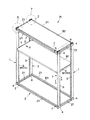
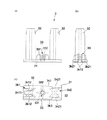
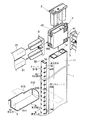
本発明に係る棚受部材の取付構造は、対向位置に起立姿勢で配置された一対の本発明の縦材たる棚受支柱5間に、棚板支持用の棚受部材6を係わり合わせて取り付ける際に適用されるものである。本実施形態においては、図1に図示するラックRに適用している。   In the mounting structure of the shelf receiving member according to the present invention, the shelf receiving member 6 for supporting the shelf plate is attached between the pair of shelf receiving columns 5 of the present invention which are arranged in a standing posture at the opposing positions. It is what is applied. In this embodiment, the present invention is applied to the rack R shown in FIG.

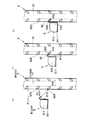
このラックRは、図1及び図2等に示すように、主として起立姿勢で配置される支柱1と、この支柱1間に架け渡される横架材2とをコーナー部材4を介して取り付けてなる略直方体状のものである。   As shown in FIG. 1 and FIG. 2, the rack R is configured by attaching a column 1 mainly arranged in a standing posture and a horizontal member 2 spanned between the columns 1 via a corner member 4. It has a substantially rectangular parallelepiped shape.

先ず、支柱1及び横架材2について説明する。   First, the support | pillar 1 and the horizontal member 2 are demonstrated.

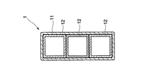
支柱1は図1及び図2等に示すように、長尺のものであり、角パイプ状の第1支柱要素11と、この第1支柱要素11の内周面に少なくとも一部が添接するように配設される複数の角パイプ状の第2支柱要素12とを備えたものである。両支柱要素11、12は、所定の長手寸法に切断することによって長手方向に沿って等断面形状をなすようにしたものであり、主として紙素材からなる。第1支柱要素11の内周面側に3本の第2支柱要素12を並列的に配設している(図3参照)。3本の第2支柱要素12のうち、両端に位置する第2支柱要素12は前記第1支柱要素11と略同一の高さ寸法を長手寸法を有するものであり、中央に位置する第2支柱要素12は、両端に位置する第2支柱要素12の長手寸法より小さい長手寸法を有するものである。   As shown in FIGS. 1 and 2, etc., the support column 1 is long, and at least a part of the first support element 11 having a square pipe shape and the inner peripheral surface of the first support element 11 are attached. And a plurality of square pipe-shaped second strut elements 12 disposed in the. Both strut elements 11 and 12 are cut into a predetermined longitudinal dimension so as to have an equal cross-sectional shape along the longitudinal direction, and are mainly made of a paper material. Three second column elements 12 are arranged in parallel on the inner peripheral surface side of the first column element 11 (see FIG. 3). Of the three second column elements 12, the second column elements 12 located at both ends have substantially the same height as the first column element 11 and have a longitudinal dimension, and the second column elements 12 located in the center. The element 12 has a longitudinal dimension smaller than the longitudinal dimension of the second strut element 12 located at both ends.

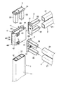
横架材2は、図1及び図2等に示すように、長尺のものであり、本実施形態においては、角パイプ状の横架材要素21を2本用いて構成している。各横架材要素21は、所定の長手寸法に切断することによって長手方向に沿って等断面形状をなすようにしたものであり、主として紙素材からなる。横架材要素21の縦断面形状と、前記第2支柱要素12の縦断面形状とを略同一形状に設定している。各横架材要素21は略同一の長手寸法を有し、長手方向両端部にエンド部材3を取り付けている。   The horizontal member 2 is long as shown in FIGS. 1 and 2 and the like, and in the present embodiment, the horizontal member 2 is configured by using two square pipe-shaped horizontal member elements 21. Each horizontal member 21 has an equal cross-sectional shape along the longitudinal direction by cutting into a predetermined longitudinal dimension, and is mainly made of a paper material. The vertical cross-sectional shape of the horizontal member 21 and the vertical cross-sectional shape of the second support column element 12 are set to substantially the same shape. Each horizontal member 21 has substantially the same longitudinal dimension, and end members 3 are attached to both ends in the longitudinal direction.

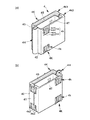
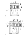
エンド部材3は、図4及び図5に示すように、例えば合成樹脂素材からなり、略矩形をなす板状の基体部31と、この基体部31から突出し前記横架材要素21の端部に嵌合可能な一対の嵌合突出部32とを備えたものである。なお、以下、基体部31の説明において、嵌合突出部32の基端部が位置する面を基体部31の表面とし、表面の反対側の面を基体部31の裏面とする。基体部31の裏面には、後述するコーナー部材4の第1係合部4Kに係合可能な第2係合部3Kを形成している。この第2係合部3Kは、主として、基体部31の長手方向一端部側に設けた略コ字形のコ字形係合片3k1と、他端部に設けた略ハ字形のハ字形係合片3k2とからなる。コ字形係合片3k1は、基体部31の長手方向一端部側において基体部31の短手方向に沿って延びる基片3k11と、基片3k11の両端から基体部31の長手方向に沿って延びる一対の対向片3k12とからなる。ハ字形係合片3k2は、基体部31の長手方向他端部側において、基体部31の短手方向両端部を長手方向に沿って且つ先端部を基体部31の中心に向かうように延ばしてなる一対の対向片3k21からなる。また、基体部31の短手方向両端部を長手方向に沿って直線状に延ばしてなる一対のレール部3k3を備えている。レール部3k3の一端部は、前記ハ字形係合片3k2の対向片3k21に連続している。   As shown in FIGS. 4 and 5, the end member 3 is made of, for example, a synthetic resin material and has a substantially rectangular plate-like base portion 31, and projects from the base portion 31 to the end of the horizontal member 21. It is provided with a pair of fitting protrusions 32 that can be fitted. Hereinafter, in the description of the base portion 31, the surface on which the base end portion of the fitting protrusion 32 is located is the surface of the base portion 31, and the surface opposite to the front surface is the back surface of the base portion 31. A second engagement portion 3K that can be engaged with a first engagement portion 4K of a corner member 4 to be described later is formed on the back surface of the base portion 31. The second engaging portion 3K is mainly composed of a substantially U-shaped engagement piece 3k1 provided on one end side in the longitudinal direction of the base portion 31, and a substantially C-shaped engagement portion 3k1 provided on the other end portion. 3k2. The U-shaped engagement piece 3k1 extends along the longitudinal direction of the base portion 31 from both ends of the base piece 3k11, and the base piece 3k11 extending along the short side direction of the base portion 31 on one longitudinal end side of the base portion 31. It consists of a pair of opposing pieces 3k12. The C-shaped engagement piece 3k2 extends on the other end in the longitudinal direction of the base portion 31 such that both ends in the short direction of the base portion 31 are along the longitudinal direction and the tip is directed toward the center of the base portion 31. It consists of a pair of opposing pieces 3k21. In addition, a pair of rail portions 3k3 is provided that is formed by extending both ends in the short direction of the base portion 31 along the longitudinal direction. One end of the rail portion 3k3 is continuous with the opposing piece 3k21 of the C-shaped engagement piece 3k2.

一対の嵌合突出部32は、基体部31の表面における長手方向略中央領域を挟んだ位置からそれぞれ突出した長尺のものである。各嵌合突出部32は、等角度で放射状に延出する4枚の羽根片を用いて形成された縦断面視略十字形のものであり、この十字形の縦断面形状が先端部に向かって漸次小さくなるように設定している。各嵌合突出部32の基端部における各羽根板を結んでなる仮想四角形が、前記横架材要素21及び第2支柱要素12の縦断面内周形状に略対応する。また、前記基体部31に、アジャスタJ等のオプション部材が取付可能な取付部33を設けている。この取付部33は、両嵌合突出部32の間に設けられた略円筒形状の筒部331に内設したナット332を用いて構成している。   The pair of fitting protrusions 32 are long ones protruding from positions sandwiching a substantially central region in the longitudinal direction on the surface of the base portion 31. Each fitting protrusion 32 has a substantially cross shape in a longitudinal cross section formed by using four blade pieces extending radially at an equal angle, and the cross section of the cross shape extends toward the tip. Is set to gradually decrease. An imaginary quadrilateral formed by connecting the blades at the base end portion of each fitting protrusion 32 substantially corresponds to the inner circumferential shape of the vertical section of the horizontal member 21 and the second support column element 12. Further, the base portion 31 is provided with an attachment portion 33 to which an optional member such as an adjuster J can be attached. The attachment portion 33 is configured by using a nut 332 provided in a substantially cylindrical tube portion 331 provided between the fitting protrusions 32.

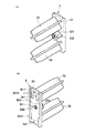
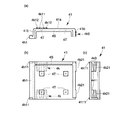
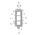
コーナー部材4は、図6乃至図9等に示すように、第1半割部材41と、この第1半割部材41と対をなす第2半割部材42とを具備するものである。各半割部材41、42は、例えば合成樹脂素材からなる平面視略コ字形状の押出成形品であり、これら半割部材41、42を概略筒状となるように組付可能に構成している。具体的に説明すると、各半割部材41、42は、組み付けた状態において相対向する対向面部41a、42aと、各対向面部41a、42aの両端部から対向面部41a、42aに直交する方向に延出する延出面部41b、42bとを有する。   As shown in FIGS. 6 to 9 and the like, the corner member 4 includes a first half member 41 and a second half member 42 that forms a pair with the first half member 41. Each of the halved members 41 and 42 is an extruded product having a substantially U shape in a plan view made of, for example, a synthetic resin material. The halved members 41 and 42 are configured to be assembled so as to be substantially cylindrical. Yes. Specifically, each half member 41, 42 extends in the direction orthogonal to the opposing surface portions 41a, 42a from the opposing surface portions 41a, 42a facing each other in the assembled state, and both ends of each opposing surface portion 41a, 42a. It has the extended surface parts 41b and 42b to protrude.

各対向面部41a、42aの外周面に第1係合部4Kを設けている。この第1係合部4Kは、対向面部41a、42aの上端部近傍領域、及び下端部近傍領域に設けた一対の単位係合部4kからなる。各単位係合部4kは、前記第2係合部3Kのコ字形係合片3k1が係合し得る第1単位係合片4k1と、第2係合部3Kのハ字形係合片3k2が係合し得る第2単位係合片4k2とを有するものである(図6(a)参照)。第2単位係合片4k2は、一対の対向片4k21から構成され、正面視略ハ字形をなすものである。第1単位係合片4k1は、第2単位係合片4k2の対向片4k21間に設けた一対の対向片4k11から構成されている。この第1単位係合片4k1は、第2単位係合片4k2とは逆向きの正面視略ハ字形をなす。これら第1単位係合片4k1と第2単位係合片4k2とを備えた単位係合部4kを、対向面部41a、42aの上端部近傍領域及び下端部近傍領域に対称となるように設けている。対向面部41a、42aの内周面には、所定部位を内方に突出させてなる突出部4Tを一体に設けている。   The first engaging portions 4K are provided on the outer peripheral surfaces of the facing surface portions 41a and 42a. The first engaging portion 4K includes a pair of unit engaging portions 4k provided in the vicinity of the upper end portion and the vicinity of the lower end portion of the facing surface portions 41a and 42a. Each unit engaging portion 4k includes a first unit engaging piece 4k1 that can be engaged with the U-shaped engaging piece 3k1 of the second engaging portion 3K, and a C-shaped engaging piece 3k2 of the second engaging portion 3K. It has the 2nd unit engagement piece 4k2 which can be engaged (refer Fig.6 (a)). The 2nd unit engagement piece 4k2 is comprised from a pair of opposing piece 4k21, and makes a front view substantially C shape. The first unit engaging piece 4k1 is composed of a pair of opposing pieces 4k11 provided between the opposing pieces 4k21 of the second unit engaging piece 4k2. The first unit engagement piece 4k1 has a substantially C shape in front view opposite to the second unit engagement piece 4k2. The unit engaging portion 4k including the first unit engaging piece 4k1 and the second unit engaging piece 4k2 is provided so as to be symmetrical with respect to the upper end portion vicinity region and the lower end portion vicinity region of the opposed surface portions 41a and 42a. Yes. On the inner peripheral surfaces of the opposed surface portions 41a and 42a, a projecting portion 4T is integrally provided by projecting a predetermined portion inward.

各半割部材41、42の一方の延出面部41b、42bには、前記第1係合部4Kを構成する係合要素4k3を設けている。係合要素4k3は、対向面部41a、42aに設けた第1係合部4Kを対向面部41a、42aの高さ方向に沿って略2等分したものである。そして、各半割部材41、42を組み付けた状態において、第1半割部材41に設けた係合要素4k3と、第2半割部材42に設けた係合要素4k3とが隣接することにより第1係合部4Kを形成するように設定している(図9(a)参照)。   Engagement elements 4k3 constituting the first engagement portion 4K are provided on one of the extending surface portions 41b and 42b of the half members 41 and 42, respectively. The engagement element 4k3 is obtained by dividing the first engagement portion 4K provided on the opposed surface portions 41a and 42a into approximately two equal parts along the height direction of the opposed surface portions 41a and 42a. And in the state which assembled | attached each half member 41,42, the engagement element 4k3 provided in the 1st half member 41 and the engagement element 4k3 provided in the 2nd half member 42 adjoin, and become 1st. One engagement portion 4K is set to be formed (see FIG. 9A).

各半割部材41、42の他方の延出面部41b、42bには、ヒンジ部4Hを構成する第1ヒンジ要素4h1、第2ヒンジ要素4h2をそれぞれ設けている。 以上の構成を有する各半割部材41、42を、各ヒンジ要素4h1、4h2を相互に嵌合させることにより、上方及び下方を開放させてなる平面視略矩形筒状のコーナー部材4が形成される。このコーナー部材4は、各ヒンジ要素4h1、4h2によって形成されるヒンジ部4Hを利用して、図9(a)に示す開成状態と、同図(b)に示す閉止状態との間で開閉動作可能に構成している。しかして、このコーナー部材4は、各半割部材41、42の外周面にそれぞれ設けた第1係合部4K、及びヒンジ部4Hに対向する位置に各係合要素4k3からなる第1係合部4Kを有する。すなわち、コーナー部材4の外周面にそれぞれ異なる方向を向くように設けた3つの第1係合部4Kを有するものとなる。また、このコーナー部材4の上方から前記エンド部材3を挿入できるようにコーナー部材4の内周寸法を設定している。さらに、エンド部材3をコーナー部材4の上方から挿入した場合に、エンド部材3のそれ以上の挿入を規制する規制部4Sを設けている。   A first hinge element 4h1 and a second hinge element 4h2 constituting the hinge part 4H are provided on the other extending surface parts 41b and 42b of the half members 41 and 42, respectively. The half members 41, 42 having the above-described configuration are fitted into the hinge elements 4h1, 4h2, thereby forming the corner member 4 having a substantially rectangular cylindrical shape in plan view in which the upper and lower sides are opened. The The corner member 4 is opened and closed between the open state shown in FIG. 9A and the closed state shown in FIG. 9B by using the hinge portion 4H formed by the hinge elements 4h1 and 4h2. It is configured as possible. Thus, the corner member 4 includes a first engagement portion 4K provided on the outer peripheral surface of each of the half members 41 and 42, and a first engagement composed of each engagement element 4k3 at a position facing the hinge portion 4H. Part 4K. In other words, the first engaging portion 4K is provided on the outer peripheral surface of the corner member 4 so as to face different directions. Further, the inner peripheral dimension of the corner member 4 is set so that the end member 3 can be inserted from above the corner member 4. Further, when the end member 3 is inserted from above the corner member 4, a restricting portion 4 </ b> S is provided that restricts further insertion of the end member 3.

このコーナー部材4に設けた第1係合部4Kと、エンド部材3に設けた第2係合部3Kとから構成される係合手段を介して、コーナー部材4に一又は複数のエンド部材3を取付可能に構成している。   One or a plurality of end members 3 are connected to the corner member 4 via engaging means constituted by a first engaging portion 4K provided on the corner member 4 and a second engaging portion 3K provided on the end member 3. Can be attached.

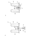
係合手段を用いたコーナー部材4とエンド部材3との取り付けるには、先ず、一の第1係合部4Kを構成する一対の単位係合部4k間に、第2係合部3Kのハ字形係合片3k2を位置させる(図10(a)、なお、同図においては、エンド部材3のコ字形係合片3k1、ハ字形係合片3k2、及びレール部3k3をパターンで示している)。次いで、エンド部材3とコーナー部材4との高さ位置を一致させ得る方向にエンド部材3をコーナー部材4の外周面に沿ってスライド移動させる。エンド部材3のスライド移動時には、エンド部材3の裏面に設けたレール部3k3が第1係合部4Kの一部に当接または近接し、コーナー部材4に対するエンド部材3の相対位置を位置決めする。このエンド部材3のスライド移動に伴って、ハ字形係合片3k2が一方の単位係合部4kの第2単位係合片4k2に係合するとともに、コ字形係合片3k1が他方の単位係合部4kの第1単位係合片4k1に係合する(同図(b))。以上の手順によりコーナー部材4とエンド部材3とを取り付ける。また、上記と逆の手順を経ることによりコーナー部材4に取り付けたエンド部材3を取り外すことができる。   In order to attach the corner member 4 and the end member 3 using the engaging means, first, the second engaging portion 3K is interposed between the pair of unit engaging portions 4k constituting the first engaging portion 4K. The U-shaped engaging piece 3k2 is positioned (FIG. 10A). In FIG. 10, the U-shaped engaging piece 3k1, the C-shaped engaging piece 3k2, and the rail portion 3k3 of the end member 3 are shown in a pattern. ). Next, the end member 3 is slid along the outer peripheral surface of the corner member 4 in a direction in which the height positions of the end member 3 and the corner member 4 can be matched. When the end member 3 slides, the rail portion 3k3 provided on the back surface of the end member 3 abuts or approaches a part of the first engaging portion 4K, and positions the end member 3 relative to the corner member 4. As the end member 3 slides, the C-shaped engagement piece 3k2 engages with the second unit engagement piece 4k2 of one unit engagement portion 4k, and the U-shaped engagement piece 3k1 engages with the other unit engagement. It engages with the first unit engagement piece 4k1 of the joint 4k (FIG. 5B). The corner member 4 and the end member 3 are attached by the above procedure. Moreover, the end member 3 attached to the corner member 4 can be removed by going through the reverse procedure to the above.

次に、複数の支柱1及び横架材2をコーナー部材4を用いて連結し、略直方体状のラックRを組み立てる一手順を説明する。   Next, a procedure for assembling a substantially rectangular parallelepiped rack R by connecting the plurality of support columns 1 and the horizontal members 2 using the corner members 4 will be described.

先ず、支柱1の上端部に、ヒンジ部4Hを利用して支柱1を抱くようにコーナー部材4を取り付ける。その際、図11に示すように、コーナー部材4を構成する各半割部材41、42の内周面に設けた各突出部4Tが第1支柱要素11の外周面に当接し、第1支柱要素11の長手方向と略直交する方向に押圧力が作用しする。次いで、コーナー部材4の上方からエンド部材3を挿入する。この挿入動作に伴い、エンド部材3の嵌合突出部32が、支柱1を構成する3本の第2支柱要素12のうち、両端に位置する各第2支柱要素12に嵌合する。エンド部材3を所定位置まで挿入すると、エンド部材3の基体部31が、コーナー部材4に設けた規制部4Sに当接し、エンド部材3のそれ以上の挿入が規制される。支柱1の下端部にもほぼ同様の手順によりコーナー部材4を取り付ける。上記手順と異なる点は、コーナー部材4を上下反転させた状態で支柱1の下端部に取り付ける点である。また、支柱1の下端部に取り付けたコーナー部材4の下方から挿入したエンド部材3に、図12に示すように、前記取付部33を利用してアジャスタJを取り付ける。このアジャスタJは、接地体J1と、取付部33のナット332に螺合可能なねじ部J2とからなるものであり、取付部33のナット332に対するねじ部J2の螺合深さ(挿入深さ)を調節することにより支柱1の高さ寸法を所定範囲内で適宜調節できるように設定している。引き続き、支柱1の上端部及び下端部に取り付けたコーナー部材4と、横架材要素21の両端部に取り付けたエンド部材3とを、前記係合手段を介して係合させる。これにより、支柱1間に横架材2が取り付けられ、略直方体状のラックRが形成される。   First, the corner member 4 is attached to the upper end of the column 1 so as to hold the column 1 using the hinge portion 4H. At this time, as shown in FIG. 11, the protrusions 4 </ b> T provided on the inner peripheral surfaces of the half members 41, 42 constituting the corner member 4 abut on the outer peripheral surface of the first column element 11, and the first column A pressing force acts in a direction substantially orthogonal to the longitudinal direction of the element 11. Next, the end member 3 is inserted from above the corner member 4. With this insertion operation, the fitting protrusion 32 of the end member 3 is fitted to each of the second column elements 12 positioned at both ends of the three second column elements 12 constituting the column 1. When the end member 3 is inserted to a predetermined position, the base portion 31 of the end member 3 comes into contact with the restricting portion 4S provided on the corner member 4, and further insertion of the end member 3 is restricted. The corner member 4 is attached to the lower end portion of the support column 1 by a substantially similar procedure. The difference from the above procedure is that the corner member 4 is attached to the lower end portion of the support column 1 while being inverted upside down. Further, as shown in FIG. 12, the adjuster J is attached to the end member 3 inserted from below the corner member 4 attached to the lower end portion of the column 1 using the attachment portion 33. The adjuster J includes a grounding body J1 and a screw portion J2 that can be screwed into the nut 332 of the mounting portion 33. The screwing depth (insertion depth) of the screw portion J2 with respect to the nut 332 of the mounting portion 33. ) Is adjusted so that the height dimension of the support column 1 can be appropriately adjusted within a predetermined range. Subsequently, the corner members 4 attached to the upper end portion and the lower end portion of the support column 1 are engaged with the end members 3 attached to both end portions of the horizontal member 21 via the engaging means. Thereby, the horizontal member 2 is attached between the support | pillars 1, and the substantially rectangular parallelepiped rack R is formed.

しかして、本実施形態においては、図1に示すように、ラックRの所定の高さ位置に棚板B1を配設している。棚板B1を配設するために、ラックRの短手方向に対向する支柱1に棚受支柱5を添接し、この棚受支柱5間に、棚板支持用の棚受部材6を係わり合わせて取り付けている。   Therefore, in the present embodiment, as shown in FIG. 1, the shelf board B1 is disposed at a predetermined height position of the rack R. In order to arrange the shelf board B 1, the shelf support column 5 is attached to the column 1 facing the short side of the rack R, and the shelf support member 6 for supporting the shelf plate is engaged between the shelf support columns 5. Attached.

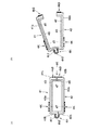
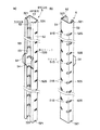
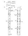
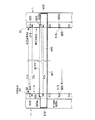
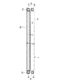
各棚受支柱5は、例えばスチール等の金属製素材からなり、図13乃至15等に図示するように、主として、他方の棚受支柱5に対向する対向面部51と、前記対向面部51の長手方向に沿った両縁部から対向面部51に略直交する方向に延びる直交面部52とを設けた平面視略コ字形をなす長尺のものである。対向面部51に、棚受支柱5の起立方向に沿って間欠的に本発明の案内部たるスリット51Sを複数設けている。各スリット51Sは、対向面部51の長手方向に沿った両縁部から棚受支柱5の起立方向に対して斜め下方に延びるものである。各スリット51Sの一端は直交面部52に開口している。これらスリット51Sを棚受支柱5の起立方向に沿って2列に設け、2列のスリット51Sを、対向面部51の起立方向に沿った所定の仮想直線(対向面部51の短手方向中心線)mに関して対称となるように設けている(図15(c)参照)。直交面部52には、各スリット51Sに連続する第2のスリット52Sを設けている。第2のスリット52Sは、棚受支柱5の起立方向に対して略直交する方向に延びるものである。すなわち第2のスリット52は略水平に延びるものである。各直交面部52の高さ方向に沿った一端部に、所定部位を除いて対向面部51に対して略平行となるように屈曲させてなる折曲面部53を設けている。各直交面部52の高さ方向に沿った一端部において折曲面部53を形成していない部位には、前記支柱1を挟持し得る挟持片54を設けている。本実施形態においては、挟持片54を棚受支柱5の長手方向略中央部にのみ設けたものを採用しているが、適宜その個数を増加したものを用いても勿論構わない。この挟持片54は、直交面部52と略平行するものであり、挟持片54間の離間距離を、直交面部52間の離間距離より若干大きくなるように設定するとともに、挟持片54間の内法寸法と、直交面部52間の外法寸法とが略一致するようにしている(同図(a)参照)。なお、直交面部52間の外法寸法は、第1支柱要素1の平面視短手寸法と略同一となるように設定されている。また、各直交面部52の上端部及び下端部にそれぞれ切欠き521を設けている。この切欠き521の開口寸法を、エンド部材3の基体部31の肉厚に略対応させている。このような構成をなす棚受支柱5の支柱1への取り付けは、各切欠き521をエンド部材3の基体部31に嵌め合わせるとともに、挟持片54を支柱1に外嵌させるようにして行う。具体的には支柱1の下端部に位置するコーナー部材4に取り付けたエンド部材3の基体部31に、直交面部52の下端部に設けた切欠521を嵌合させるとともに、折曲面部53を支柱1に当接または近接させて挟持片54によって支柱1を外嵌し得るようにする。次いで、支柱1の上端部に位置するコーナー部材4にエンド部材3を取り付けることにより、エンド部材3の基体部31が直交面部52の上端部に設けた切欠521に嵌合する。この取付状態においては、各切欠き521がエンド部材3の基体部31に嵌合することにより棚受支柱5の上下方向の移動が規制され、挟持片54が支柱1を外嵌することにより棚受支柱5の横方向の移動が規制される。   Each shelf support column 5 is made of, for example, a metal material such as steel, and as shown in FIGS. 13 to 15 and the like, mainly the opposed surface portion 51 facing the other shelf support column 5 and the longitudinal length of the opposed surface portion 51. It is a long one having a substantially U-shape in plan view provided with an orthogonal surface portion 52 extending in a direction substantially orthogonal to the opposing surface portion 51 from both edge portions along the direction. A plurality of slits 51 </ b> S serving as guide portions of the present invention are provided on the facing surface portion 51 intermittently along the rising direction of the shelf support column 5. Each slit 51 </ b> S extends obliquely downward with respect to the standing direction of the shelf support column 5 from both edges along the longitudinal direction of the facing surface portion 51. One end of each slit 51 </ b> S opens in the orthogonal surface portion 52. These slits 51S are provided in two rows along the standing direction of the shelf support column 5, and two rows of slits 51S are defined as predetermined virtual straight lines along the standing direction of the facing surface portion 51 (the center line in the short direction of the facing surface portion 51). They are provided so as to be symmetric with respect to m (see FIG. 15C). The orthogonal plane portion 52 is provided with a second slit 52S that is continuous with each slit 51S. The second slit 52S extends in a direction substantially orthogonal to the standing direction of the shelf support column 5. That is, the second slit 52 extends substantially horizontally. At one end portion along the height direction of each orthogonal surface portion 52, a bent surface portion 53 that is bent so as to be substantially parallel to the opposing surface portion 51 except for a predetermined portion is provided. A clamping piece 54 that can clamp the support column 1 is provided at a portion where the folded curved surface portion 53 is not formed at one end portion along the height direction of each orthogonal surface portion 52. In the present embodiment, the sandwiching piece 54 is provided only at the substantially central portion in the longitudinal direction of the shelf support column 5, but it is of course possible to use a structure in which the number is increased as appropriate. The sandwiching piece 54 is substantially parallel to the orthogonal surface portion 52, and the separation distance between the sandwiching pieces 54 is set to be slightly larger than the separation distance between the orthogonal surface portions 52. The dimension and the outer dimension between the orthogonal surface portions 52 are substantially matched (see FIG. 5A). The outer dimension between the orthogonal surface portions 52 is set to be substantially the same as the short dimension in plan view of the first support column element 1. Moreover, the notch 521 is provided in the upper end part and lower end part of each orthogonal surface part 52, respectively. The opening size of the notch 521 is made to substantially correspond to the thickness of the base portion 31 of the end member 3. The shelf support column 5 having such a configuration is attached to the column 1 by fitting each notch 521 to the base 31 of the end member 3 and fitting the holding piece 54 to the column 1. Specifically, the notch 521 provided in the lower end portion of the orthogonal surface portion 52 is fitted to the base portion 31 of the end member 3 attached to the corner member 4 positioned at the lower end portion of the support column 1, and the folded curved surface portion 53 is used as the support column. The support column 1 can be externally fitted by the sandwiching piece 54 in contact with or close to 1. Next, by attaching the end member 3 to the corner member 4 positioned at the upper end portion of the support column 1, the base portion 31 of the end member 3 is fitted into the notch 521 provided at the upper end portion of the orthogonal surface portion 52. In this attached state, each notch 521 is fitted to the base portion 31 of the end member 3 to restrict the vertical movement of the shelf receiving column 5, and the holding piece 54 is fitted to the column 1 to externally attach the shelf. The lateral movement of the receiving column 5 is restricted.

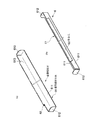
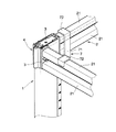
一方、棚受部材6は、例えばスチール等の金属性素材からなり、図16等に示すように、棚受支柱5間に略水平姿勢で取り付けられる長尺のものである。この棚受部材6は、棚受部材本体61と、前記スリット51Sの傾斜角度に対応する角度をなして棚受部材本体61から突出する本発明の被案内部たる係合爪62とを備えたものである。棚受部材本体61は、棚板B1の一部を載置し得る載置部611と、載置部611の長手方向両端部を起立させてなる第1起立部612と、載置部611の長手方向に沿った一端部を起立させてなる第2起立部613とを有するものである。この第2起立部613の上端部に前記係合爪62を一体に設けている。係合爪62は、第2起立部613の上端部から斜め後下方に向かって延出するものである。この斜め後下方に向かって延出する係合爪62の延出寸法を、斜め方向に延びる前記棚受支柱5のスリット51Sの延出寸法と略同一又は若干短く設定している。また、係合爪62の長手寸法を、棚受部材本体61の長手寸法より短く設定し、第2起立部613の長手方向両端部に係合爪62を設けていない領域を形成している。係合爪62の長手寸法62xは、対向配置された棚受支柱5の対向面部51間の離間距離51xより大きく、且つ第2のスリット52Sの延出方向の開口縁部52Sa間の離間距離52xより若干小さく設定されている(図18参照)。   On the other hand, the shelf receiving member 6 is made of a metal material such as steel, for example, and is a long one that is attached between the shelf receiving columns 5 in a substantially horizontal posture as shown in FIG. The shelf receiving member 6 includes a shelf receiving member main body 61 and an engaging claw 62 as a guided portion of the present invention that protrudes from the shelf receiving member main body 61 at an angle corresponding to the inclination angle of the slit 51S. Is. The shelf receiving member main body 61 includes a placement portion 611 on which a part of the shelf board B1 can be placed, a first standing portion 612 formed by raising both longitudinal ends of the placement portion 611, and the placement portion 611. It has the 2nd standing part 613 which stands up the one end part along a longitudinal direction. The engaging claw 62 is integrally provided at the upper end portion of the second upright portion 613. The engagement claw 62 extends obliquely rearward and downward from the upper end portion of the second upright portion 613. The extension dimension of the engaging claw 62 extending obliquely rearward and downward is set to be substantially the same as or slightly shorter than the extension dimension of the slit 51S of the shelf support column 5 extending in the oblique direction. Further, the longitudinal dimension of the engaging claw 62 is set to be shorter than the longitudinal dimension of the shelf receiving member main body 61, and a region where the engaging claw 62 is not provided is formed at both longitudinal ends of the second upright part 613. The longitudinal dimension 62x of the engagement claw 62 is larger than the separation distance 51x between the opposed surface portions 51 of the shelf support columns 5 arranged opposite to each other, and the separation distance 52x between the opening edge portions 52Sa in the extending direction of the second slit 52S. It is set slightly smaller (see FIG. 18).

この棚受支柱5に設けたスリット51Sと、棚受部材6に設けた係合爪62とから構成される案内手段を介して、棚受支柱5間に棚受部材6を取付可能に構成している。   The shelf support member 6 is configured to be attachable between the shelf support posts 5 via a guide means including a slit 51S provided in the shelf support post 5 and an engaging claw 62 provided in the shelf support member 6. ing.

案内手段を用いて棚受支柱5間に棚受部材6を取り付ける手順、及び棚受部材6を利用して棚板Bを配設する手順を図17を参照して説明する。なお、この棚板B1は、木質のもの、又はスチール素材のもの等、周知のものを採用している。   A procedure for attaching the shelf receiving member 6 between the shelf receiving columns 5 using the guide means and a procedure for arranging the shelf board B using the shelf receiving member 6 will be described with reference to FIG. In addition, this shelf board B1 employ | adopts a well-known thing, such as a thing of a wooden thing, or a steel material.

棚受支柱5間に棚受部材6を取り付けるには、先ず、棚受部材6を所望の取付高さ位置に形成したスリット51Sの近傍に持ち来る(同図(a))。次いで、棚受部材6の係合爪62をスリット51Sに斜め上方から挿入する。係合爪62をスリット51Sに挿入するにあたっては、係合爪62の長手方向両端部を直行面部52に形成した第2のスリット52Sに挿入する(同図(b))。このように、直交面部52に形成した第2のスリット52Sは、係合爪62の挿入口(導入口)としての役割を担う。引き続き、係合爪62をスリット51Sに案内させるようにして棚受部材6を棚受支柱5の起立方向に対して斜め下方にスライド移動させる。このスライド動作に伴って棚受部材6の棚受支柱5に対する係合深さが漸次深くなる。また、棚受部材6を所定距離スライド移動させると、棚受部材6の第2起立部613の長手方向両端部近傍領域が、棚受支柱5の直交面部52及び支柱1(第1支柱要素11)に当接する(同図(c))。つまり、第2起立部613の一部が本発明の当たり部として機能する。以上の手順を経て対向位置に起立姿勢で配置された一対の棚受支柱5間に棚受部材6を取り付ける。この取付状態において係合爪62とスリット52との係合深さが最も深くなるように設定している。また、この取付状態においては、図18に示すように、係合爪62の長手方向両端部と、第2のスリット52Sの延出方向の開口縁部52Saとが当接又は近接し、各棚受支柱5が互いに相寄る方向に移動することを規制している。そして、平面視矩形の板状の棚板B1の一部を棚受部材6の載置部611に載置するようにして棚受部材6に支持させる。これにより、ラックRの所定の高さ位置に棚板B1が配設される。また、棚受支柱5間に取り付けた棚受部材6を取り外すには、係合爪62をスリット51Sに案内させながら棚受部材6を棚受支柱5の起立方向に対して斜め上方にスライド移動させる。このスライド動作に伴って、係合爪62とスリット51Sとの係合が解除され、棚受部材6を取り外すことができる。   In order to attach the shelf support member 6 between the shelf support columns 5, first, the shelf support member 6 is brought in the vicinity of the slit 51S formed at a desired mounting height position ((a) in the figure). Next, the engaging claws 62 of the shelf receiving member 6 are inserted into the slit 51S from obliquely above. In inserting the engaging claw 62 into the slit 51S, both end portions in the longitudinal direction of the engaging claw 62 are inserted into the second slit 52S formed in the orthogonal surface portion 52 ((b) in the figure). As described above, the second slit 52S formed in the orthogonal surface portion 52 plays a role as an insertion port (introduction port) of the engagement claw 62. Subsequently, the shelf receiving member 6 is slid and moved obliquely downward with respect to the standing direction of the shelf receiving column 5 so that the engaging claw 62 is guided to the slit 51S. With this sliding operation, the engagement depth of the shelf receiving member 6 with respect to the shelf receiving column 5 gradually increases. Further, when the shelf receiving member 6 is slid and moved by a predetermined distance, the regions in the vicinity of both ends in the longitudinal direction of the second upright portion 613 of the shelf receiving member 6 become the orthogonal surface portion 52 of the shelf receiving support column 5 and the support column 1 (the first support column element 11). (Fig. 3C). That is, a part of the second upright part 613 functions as a hit part of the present invention. The shelf receiving member 6 is attached between the pair of shelf receiving columns 5 arranged in a standing posture at the opposite position through the above procedure. In this mounted state, the engagement depth between the engagement claw 62 and the slit 52 is set to be the deepest. Further, in this attached state, as shown in FIG. 18, both end portions in the longitudinal direction of the engaging claws 62 and the opening edge portion 52Sa in the extending direction of the second slit 52S are in contact with or close to each other. The receiving struts 5 are restricted from moving in the direction of mutual approach. And a part of plate-shaped shelf board B1 of a planar view rectangle is supported by the shelf receiving member 6 so that it may be mounted in the mounting part 611 of the shelf receiving member 6. FIG. Thereby, the shelf board B1 is disposed at a predetermined height position of the rack R. In addition, in order to remove the shelf receiving member 6 attached between the shelf receiving posts 5, the shelf receiving member 6 is slid and moved obliquely upward with respect to the standing direction of the shelf receiving posts 5 while guiding the engaging claws 62 to the slits 51 </ b> S. Let With this sliding operation, the engagement between the engagement claw 62 and the slit 51S is released, and the shelf receiving member 6 can be removed.

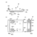
なお、本実施形態においては、ラックRの上端部に天板B2を配設するとともに、下端部に底板B3を配設している(図1参照)。天板B2又は底板B3を配設するために、ラックRの平面視短手方向に対向する横架材2間に、各板材支持用の支持部材7を架け渡すようにして取り付けている。   In the present embodiment, the top plate B2 is disposed at the upper end portion of the rack R, and the bottom plate B3 is disposed at the lower end portion (see FIG. 1). In order to dispose the top plate B2 or the bottom plate B3, the support members 7 for supporting the respective plate materials are attached so as to be bridged between the horizontal members 2 facing the rack R in the short side view in the plan view.

支持部材7は、図19に示すように、一枚の金属製素材を折曲成形してなるものである。長尺の基部71と、基部71の長手方向両端部を略コ字形に折り曲げてなる掛止部72とを備えたものである。この掛止部72は、横架材2を構成する横架材要素21の外周面に添接し得るように設定したものである。そして、各掛止部72を横架材要素21に引っ掛けるようにして横架材2間に支持部材7を取り付ける。このようにして複数の支持部材7を横架材2間に取り付け、各支持部材7の基部71上に天板B2又は底板B3を載置するようにして配設する。なお、本実施形態においては、ラックRの平面視短手方向に対向する横架材2間に支持部材7を取り付けているが、ラックRの平面視長手方向に対向する横架材2間に支持部材7を取り付けてもよい。このように、本実施形態においては、対向する横架材2間に支持部材7を取付可能に構成している。また、ラックRの組立強度を向上させるために、図20に示すように、コーナー部材4を介して直交する横架材2(横架材要素21)間を跨ぐ位置に支持部材7を取り付けるようにしても構わない。支持部材7は上記各取付位置に合わせて基部71の長手寸法等を適宜変更しているのはもちろんである。また、支持部材7の取付位置を選択することによって、天板B2または底板B3の高さ位置を変更することができるように構成している。具体的には、横架材2を構成する一方の横架材要素21に取り付けている支持部材7を、他方の横架材要素21に取り付けることにより、天板B2または底板B3の高さ位置を変更することができる。なお、棚板B1、天板B2又は底板B3の替わりに、複数の紙管を敷設しても構わない。この紙管として例えば架材要素や第2支柱要素12を用いるようにしてもよい。   As shown in FIG. 19, the support member 7 is formed by bending a single metal material. A long base portion 71 and a hooking portion 72 formed by bending both longitudinal ends of the base portion 71 into a substantially U shape are provided. This latching portion 72 is set so as to be able to contact the outer peripheral surface of the horizontal member 21 constituting the horizontal member 2. Then, the support member 7 is attached between the horizontal members 2 so that the hooks 72 are hooked on the horizontal member 21. In this way, the plurality of support members 7 are attached between the horizontal members 2, and the top plate B <b> 2 or the bottom plate B <b> 3 is placed on the base 71 of each support member 7. In the present embodiment, the support member 7 is attached between the horizontal members 2 facing in the short side direction of the rack R in the plan view, but between the horizontal members 2 facing the longitudinal direction of the rack R in the plan view. A support member 7 may be attached. Thus, in this embodiment, it is comprised so that attachment of the supporting member 7 is possible between the horizontal members 2 which oppose. Further, in order to improve the assembly strength of the rack R, as shown in FIG. 20, the support member 7 is attached at a position straddling between the horizontal members 2 (horizontal member elements 21) orthogonal to each other via the corner members 4. It doesn't matter. Of course, the support member 7 appropriately changes the longitudinal dimension and the like of the base portion 71 in accordance with the respective mounting positions. Further, the height position of the top plate B2 or the bottom plate B3 can be changed by selecting the mounting position of the support member 7. Specifically, the height position of the top plate B2 or the bottom plate B3 is obtained by attaching the support member 7 attached to one horizontal member 21 constituting the horizontal member 2 to the other horizontal member 21. Can be changed. A plurality of paper tubes may be laid instead of the shelf board B1, the top board B2 or the bottom board B3. As the paper tube, for example, a frame member or the second support column element 12 may be used.

このように、本実施形態に係る棚受部材の取付構造は、対向配置される棚受支柱5の相対向する対向面部51に、棚受支柱5の起立方向に対して斜めに設けたスリット51Sと、棚受部材6に設けられスリット51Sに案内され得る係合爪62とからなる案内手段を備え、この案内手段を利用して棚受部材6を棚受支柱5の起立方向に対して斜め下方にスライド移動させることにより棚受部材6の棚受支柱5に対する係合深さが漸次深くなるように構成しているため、棚受部材5を斜め下方に落とし込むという操作のみで案内手段を介して棚受部材5を支柱に係合させることが可能となり、ビスや係合ピン等を用いることなく、棚受部材6を棚受支柱5間に簡単に取り付けることができる。また、上記実施形態においては、棚受部材6を棚受支柱5間に取り付けた状態において棚受部材6と棚受支柱5との係合深さが最も深くなるように設定しているため、棚受部材6と棚受支柱5との取付状態もより良好なものとなる。また、棚受支柱5間に取り付けた棚受部材6を斜め上方にスライドさせることによって棚受部材6を取り外すことができる。このように、棚受支柱5間に棚受部材6を取り付ける作業、及び棚受支柱5間から棚受部材を取り外す作業をワンアクションで行うことができ、極めて操作性に優れたものである。   Thus, the mounting structure of the shelf receiving member according to the present embodiment has the slits 51S provided obliquely with respect to the standing direction of the shelf receiving support column 5 on the opposed surface portions 51 of the shelf receiving support columns 5 that are arranged to face each other. And an engaging claw 62 provided on the shelf receiving member 6 and capable of being guided by the slit 51S. The shelf receiving member 6 is inclined with respect to the standing direction of the shelf receiving column 5 by using this guiding means. Since the engaging depth of the shelf receiving member 6 with respect to the shelf receiving support column 5 is gradually increased by sliding downward, only the operation of dropping the shelf receiving member 5 obliquely downward is performed via the guide means. Thus, the shelf support member 5 can be engaged with the support column, and the shelf support member 6 can be easily attached between the shelf support support columns 5 without using screws or engagement pins. Moreover, in the said embodiment, since it has set so that the engagement depth of the shelf receiving member 6 and the shelf receiving support | pillar 5 may become the deepest in the state which attached the shelf receiving member 6 between the shelf receiving support | pillars 5, The mounting state of the shelf receiving member 6 and the shelf receiving column 5 is also better. Further, the shelf receiving member 6 can be removed by sliding the shelf receiving member 6 attached between the shelf receiving columns 5 obliquely upward. Thus, the operation | work which attaches the shelf receiving member 6 between the shelf receiving support | pillars 5, and the operation | work which removes a shelf receiving member from between the shelf receiving support | pillars 5 can be performed by one action, and it is excellent in operability.

前記棚受支柱5が、対向面部51と、この対向面部51に略直交する直交面部52とを備え、対向面部51の長手方向に沿った縁部に連続して直交面部52を設けたものであり、各スリット51Sの一端を直交面部52に開口させるとともに、この直交面部52に、各スリット51Sに連続する第2のスリット52Sを設けているため、第2のスリット52Sを、係合爪62をスリット51Sに挿入する際の目印として視認することができるとともに、係合爪62を第2のスリット52Sから挿入してそのままスリットに係合させることが可能となり、取付作業性の向上に資する。   The shelf support column 5 includes an opposing surface portion 51 and an orthogonal surface portion 52 substantially orthogonal to the opposing surface portion 51, and the orthogonal surface portion 52 is provided continuously to the edge portion along the longitudinal direction of the opposing surface portion 51. Yes, one end of each slit 51S is opened to the orthogonal surface portion 52, and the second surface 52S is provided in the orthogonal surface portion 52 so as to be continuous with each slit 51S. Can be visually recognized as a mark at the time of insertion into the slit 51S, and the engaging claw 62 can be inserted from the second slit 52S and can be engaged with the slit as it is, which contributes to improvement in mounting workability.

加えて、第2のスリット52Sが、各スリット51Sに連続して略水平方向に延ばしたものであり、棚受支柱5間に棚受部材6を取り付けた状態において、係合爪62の一部と、第2のスリット52Sの延出方向の開口縁部52Saとが当接又は近接し、各棚受支柱5が互いに相寄る方向に移動することを規制するように構成しているため、良好な取付状態を維持することができる。   In addition, the second slit 52S extends in a substantially horizontal direction continuously to each slit 51S, and a part of the engagement claw 62 is attached in a state where the shelf support member 6 is attached between the shelf support columns 5. And the opening edge portion 52Sa in the extending direction of the second slit 52S is in contact with or close to each other, and the shelf receiving support columns 5 are configured to be restricted from moving in the direction of mutual contact. Can be maintained.

また、スリット51Sを、対向面部51の長手方向に沿って間欠的に複数設けているため、所望の高さ位置に位置するスリット51Sに棚受部材6を取り付けることができる。このように、棚受部材6の取付位置を選択可能に構成しているため、棚板B1の配置変更も容易に行うことができる。また、棚受支柱5の起立方向に沿って複数の棚受部材6を取り付けることも可能であり、実用的である。   Moreover, since the plurality of slits 51S are intermittently provided along the longitudinal direction of the facing surface portion 51, the shelf support member 6 can be attached to the slit 51S located at a desired height position. Thus, since the attachment position of the shelf receiving member 6 can be selected, the arrangement of the shelf board B1 can be easily changed. Further, it is possible to attach a plurality of shelf receiving members 6 along the standing direction of the shelf receiving support column 5, which is practical.

さらに、スリット51Sを棚受支柱5の起立方向に沿って2列に設け、一方の列のスリット51S又は両列のスリット51Sを利用して、棚受部材6を棚受支柱5間に取付可能に構成しているため、一対の棚受支柱5に対して2方向からそれぞれ棚受部材6を取り付けることもでき、種々の使用態様に柔軟に対応させることができる。   Furthermore, the slits 51S are provided in two rows along the standing direction of the shelf support columns 5, and the shelf support members 6 can be attached between the shelf support columns 5 using the slits 51S of one column or the slits 51S of both columns. Therefore, the shelf support members 6 can be attached to the pair of shelf support posts 5 from two directions, respectively, and can be flexibly adapted to various usage modes.

2列に形成したスリット51Sを、対向面部51の起立方向に沿った所定の仮想直線mに関して対称となるように設けているため、一対の棚受支柱5に対して2方向からそれぞれ棚受部材6を取り付けた場合、各棚受部材6の取付高さ位置を揃えることができる。   Since the slits 51 </ b> S formed in two rows are provided so as to be symmetric with respect to a predetermined virtual straight line m along the standing direction of the facing surface portion 51, the shelf receiving members from the two directions with respect to the pair of shelf receiving columns 5 respectively When 6 is attached, the attachment height position of each shelf receiving member 6 can be aligned.

棚受部材6が、棚板B1を支持する棚受部材本体61と、スリット51Sの傾斜角度に対応する角度をなして棚受部材本体61から突出する係合爪62とを備えたものであり、棚受部材本体61に、棚受部材6を棚受支柱5間に取り付けた状態において直交面部51に当接または近接する当たり部(上記実施形態における第2起立部613の長手方向両端部近傍領域)を設けているため、当たり部が直交面部52に当たることにより、棚受部材6を棚受支柱5間に取り付けた状態において棚受部材6がガタつくことなく、取付状態をより良好なものとすることができる。   The shelf receiving member 6 includes a shelf receiving member main body 61 that supports the shelf board B1 and an engaging claw 62 that protrudes from the shelf receiving member main body 61 at an angle corresponding to the inclination angle of the slit 51S. In the state in which the shelf receiving member 6 is mounted between the shelf receiving columns 5 on the shelf receiving member main body 61, the contact portions that are in contact with or close to the orthogonal surface portion 51 (in the vicinity of both longitudinal ends of the second upright portion 613 in the above embodiment) Since the contact portion hits the orthogonal surface portion 52, the shelf receiving member 6 does not rattle in the state in which the shelf receiving member 6 is attached between the shelf receiving columns 5 and the mounting state is better. It can be.

また、棚受支柱5が、対向位置に起立姿勢で配置された支柱1に取付可能に構成したものであるため、対向配置された各支柱1にそれぞれ棚受支柱5を取り付けて、この棚受支柱5間に棚受部材6を取り付けることにより支柱1間に棚受部材6を架設することができる。この場合、支柱1自体にスリット等を形成する必要はなく、例えば既存の支柱1を利用することができる。   Further, since the shelf support column 5 is configured to be attachable to the column 1 arranged in the standing position at the opposite position, the shelf column support column 5 is attached to each column 1 arranged opposite to the shelf column. By attaching the shelf receiving member 6 between the columns 5, the shelf receiving member 6 can be installed between the columns 1. In this case, it is not necessary to form a slit or the like in the support column 1 itself, and for example, the existing support column 1 can be used.

特に、棚受支柱5及び棚受部材6が金属製素材からなるものであるため、棚受支柱5及び棚受部材6の剛性を強くすることができる。これにより、スリットの開口縁がちぎれる等して開口幅が拡がる等の不具合が生じることなく、スリット51Sと係合爪62との係合状態を良好なものにすることができる。また、分別廃棄にも適するものとなる。   In particular, since the shelf receiving column 5 and the shelf receiving member 6 are made of a metal material, the rigidity of the shelf receiving column 5 and the shelf receiving member 6 can be increased. Thereby, the engagement state of the slit 51S and the engagement claw 62 can be made favorable without causing problems such as the opening edge of the slit being broken to widen the opening width. It is also suitable for sorting and disposal.

なお、本発明は、以上に詳述した実施形態に限られるものではない。   The present invention is not limited to the embodiment described in detail above.

例えば、案内部として、溝や突状のものを用いて構わない。案内部に合わせて被案内部も係合爪に替えて適宜のものを採用してもよい。   For example, a groove or a protrusion may be used as the guide portion. In accordance with the guide portion, the guided portion may be replaced with an appropriate one instead of the engaging claw.

また、案内部を棚受支柱の起立方向に沿って1列のみに設けたものであってもよい。   Moreover, the guide part may be provided in only one row along the standing direction of the shelf support column.

また、縦材間に棚受部材を取り付けた状態において、棚受部材本体の長手方向両端部によって各縦材の外周面を抱え込むように設定し、各縦材が互いに相離反する方向に移動することを規制するように構成してもよい。   Further, in a state in which the shelf support member is attached between the longitudinal members, the longitudinal member is set so as to hold the outer peripheral surface of each longitudinal member by the longitudinal ends of the shelf support member main body, and the longitudinal members are moved away from each other. You may comprise so that this may be controlled.

上記実施形態においては、縦材として、支柱1に添接するように配設される棚受支柱6を明示したが、縦材が支柱そのものとして機能するものであっても構わない。このようなものであれば、上記実施形態と比較して部品点数の削減を図ることができる。また、支柱に添接するように取り付けられ縦材自体は支柱として機能しないものであっても構わない。   In the above-described embodiment, the shelf support column 6 disposed so as to be in contact with the column 1 is clearly shown as the vertical member. However, the vertical member may function as the column itself. If it is such, reduction of a number of parts can be aimed at compared with the said embodiment. Further, the vertical member attached so as to be in contact with the support may not function as a support.

本願に係る棚受部材の取付構造を前記ラックR以外の構造体に適用してもよいのはもちろんである。   Of course, the mounting structure of the shelf receiving member according to the present application may be applied to a structure other than the rack R.

その他、各部の具体的構成についても上記実施形態に限られるものではなく、本発明の趣旨を逸脱しない範囲で種々変形が可能である。   In addition, the specific configuration of each part is not limited to the above embodiment, and various modifications can be made without departing from the spirit of the present invention.

本発明の一実施形態におけるラックの全体斜視図。The whole perspective view of the rack in one embodiment of the present invention. 図1におけるX領域の拡大分解斜視図を一部省略して示す図。The figure which abbreviate | omits and shows the expansion exploded perspective view of X area | region in FIG. 図1におけるA−A線断面における支柱を拡大して示す図。The figure which expands and shows the support | pillar in the AA cross section in FIG. 同実施形態におけるエンド部材の全体斜視図。The whole perspective view of the end member in the embodiment. 同エンド部材を示す図。The figure which shows the end member. 同実施形態におけるコーナー部材の全体斜視図。The whole corner member perspective view in the embodiment. 同実施形態における第1半割部材を示す図。The figure which shows the 1st half member in the embodiment. 同実施形態における第2半割部材を示す図。The figure which shows the 2nd half member in the embodiment. 同実施形態におけるコーナー部材の作用説明図。Action | operation explanatory drawing of the corner member in the embodiment. 同実施形態における係合手段の作用説明図。Action | operation explanatory drawing of the engagement means in the embodiment. 同実施形態における押圧手段の作用説明図。Action | operation explanatory drawing of the press means in the same embodiment. 同実施形態におけるオプション部材の取付説明図。The attachment explanatory view of the option member in the embodiment. 図1におけるY領域の拡大分解斜視図。FIG. 2 is an enlarged exploded perspective view of a Y region in FIG. 1. 同実施形態における棚受支柱を一部省略して示す全体斜視図。The whole perspective view which abbreviate | omits and shows the shelf receiving support | pillar in the same embodiment. 同棚受支柱を示す図。The figure which shows the same shelf receiving support | pillar. 同実施形態における棚受部材を一部省略して示す全体斜視図。The whole perspective view which abbreviate | omits and shows the shelf receiving member in the embodiment partially. 同実施形態における棚受部材の取付説明図。The attachment explanatory view of the shelf receiving member in the embodiment. 同棚受部材を棚受支柱間に取り付けた状態を図1におけるP方向から見た図。The figure which looked at the state which attached the shelf receiving member between the shelf support pillars from the P direction in FIG. 図1におけるB−B線端面を模式的に示す図。The figure which shows typically the BB line end surface in FIG. 同実施形態における支持部材の変形例を示す図。The figure which shows the modification of the supporting member in the embodiment.

符号の説明Explanation of symbols

5…棚受支柱
51…対向面部
51S…案内部(スリット)
52…直交面部
52S…第2のスリット
52Sa…開口縁部
6…棚受部材
62…被案内部(係合爪)
5 ... Shelf support column 51 ... Opposite surface part 51S ... Guide part (slit)
52 ... Orthogonal surface portion 52S ... Second slit 52Sa ... Opening edge portion 6 ... Shelf receiving member 62 ... Guided portion (engaging claw)

Claims (12)

対向位置に起立姿勢で配置された一対の縦材間に、棚板支持用の棚受部材を係わり合わせて取り付ける際に適用される棚受部材の取付構造であって、
前記両縦材の相互に対向する対向面部に縦材の起立方向に対して斜めに設けた案内部と、前記棚受部材に設けられ前記案内部に案内され得る被案内部とからなる案内手段を備え、当該案内手段を利用して前記棚受部材を前記縦材の起立方向に対して斜め下方にスライド移動させることにより棚受部材の縦材に対する係合深さが漸次深くなるように構成したことを特徴とする棚受部材の取付構造。
A shelf support member mounting structure applied when a shelf support member for supporting a shelf plate is engaged and installed between a pair of vertical members arranged in an upright position at opposite positions,
Guide means comprising a guide portion provided obliquely with respect to the standing direction of the vertical member on the opposing surface portions of the two vertical members facing each other, and a guided portion provided on the shelf receiving member and capable of being guided by the guide portion And by using the guide means to slide the shelf receiving member obliquely downward with respect to the vertical direction of the vertical member, the depth of engagement of the shelf receiving member with the vertical member is gradually increased. A mounting structure for a shelf receiving member, characterized in that
前記案内部が前記対向面部に形成したスリットであり、前記棚受部材に設けた被案内部が前記スリットに係合可能な係合爪である請求項1記載の棚受部材の取付構造。 The shelf receiving member mounting structure according to claim 1, wherein the guide portion is a slit formed in the facing surface portion, and the guided portion provided in the shelf receiving member is an engaging claw that can engage with the slit. 前記縦材が、前記対向面部と、当該対向面部に略直交する直交面部とを備え、前記対向面部の長手方向に沿った縁部に連続して前記直交面部を設けたものであり、前記各スリットの一端を前記直交面部に開口させるとともに、当該直交面部に、前記各スリットに連続する第2のスリットを設けている請求項2記載の棚受部材の取付構造。 The vertical member includes the facing surface portion and an orthogonal surface portion substantially orthogonal to the facing surface portion, and the orthogonal surface portion is provided continuously to an edge along the longitudinal direction of the facing surface portion. The shelf receiving member mounting structure according to claim 2, wherein one end of the slit is opened in the orthogonal surface portion, and a second slit is provided in the orthogonal surface portion so as to be continuous with each of the slits. 前記第2のスリットが、前記各スリットに連続して所定方向に延ばしたものであり、前記縦材間に前記棚受部材を取り付けた状態において、前記係合爪の一部と、前記第2のスリットの延出方向の開口縁部とが当接又は近接し、各縦材が互いに相寄る方向に移動することを規制するように構成している請求項3記載の棚受部材の取付構造。 The second slit extends in a predetermined direction continuously to each slit, and in a state where the shelf support member is attached between the longitudinal members, a part of the engaging claw, and the second The shelf receiving member mounting structure according to claim 3, wherein the longitudinal edges of the slits are in contact with or close to each other and are restricted from moving in the direction in which the vertical members are close to each other. . 前記案内部を、前記対向面部の長手方向に沿って間欠的に複数設けている請求項1、2、3又は4記載の棚受部材の取付構造。 The shelf receiving member mounting structure according to claim 1, 2, 3, or 4, wherein a plurality of the guide portions are provided intermittently along the longitudinal direction of the facing surface portion. 前記案内部を前記縦材の起立方向に沿って2列に設け、一方の案内部又は両方の案内部を利用して、前記棚受部材を前記縦材間に取付可能に構成している請求項1、2、3、4又は5記載の棚受部材の取付構造。 The said guide part is provided in 2 rows along the standing direction of the said vertical member, The said shelf receiving member is comprised so that attachment between the said vertical members is possible using one guide part or both guide parts. Item 6. The structure for mounting a shelf receiving member according to Item 1, 2, 3, 4 or 5. 前記2列の案内部を、前記対向面部の起立方向に沿った所定の仮想直線に関して対称となるように設けている請求項6記載の棚受部材の取付構造。 The shelf receiving member mounting structure according to claim 6, wherein the two rows of guide portions are provided so as to be symmetric with respect to a predetermined virtual straight line along the rising direction of the facing surface portion. 前記棚受部材が、前記縦材間に略水平姿勢で取り付けられる長尺のものであり、棚板を支持する棚受部材本体と、前記案内部の傾斜角度に対応する角度をなして前記棚受部材本体から突出する被案内部とを備えたものである請求項1、2、3、4、5、6又は7記載の棚受部材の取付構造。 The shelf support member is a long one attached between the vertical members in a substantially horizontal posture, and the shelf support member main body that supports the shelf board and the shelf at an angle corresponding to the inclination angle of the guide portion The shelf receiving member mounting structure according to claim 1, further comprising a guided portion protruding from the receiving member main body. 前記棚受部材本体に、棚受部材を縦材間に取り付けた状態において前記直交面部に当接または近接する当たり部を設けている請求項8記載の棚受部材の取付構造。 The shelf receiving member mounting structure according to claim 8, wherein the shelf receiving member main body is provided with a contact portion in contact with or close to the orthogonal surface portion in a state in which the shelf receiving member is attached between the vertical members. 前記縦材が、支柱として使用されるものである請求項1、2、3、4、5、6、7、8又は9記載の棚受部材の取付構造。 The shelf support member mounting structure according to claim 1, wherein the longitudinal member is used as a support column. 前記縦材が、対向位置に起立姿勢で配置された支柱に取付可能に構成したものである請求項1、2、3、4、5、6、7、8又は9記載の棚受部材の取付構造。 The shelf support member according to claim 1, 2, 3, 4, 5, 6, 7, 8 or 9, wherein the longitudinal member is configured to be attachable to a support column disposed in an upright position at an opposing position. Construction. 前記縦材及び前記棚受部材が金属製素材からなる請求項1、2、3、4、5、6、7、8、9、10又は11記載の棚受部材の取付構造。 The shelf support member mounting structure according to claim 1, 2, 3, 4, 5, 6, 7, 8, 9, 10 or 11, wherein the vertical member and the shelf support member are made of a metal material.
JP2003305495A 2003-08-28 2003-08-28 Attachment structure of rack receiving member Pending JP2005073791A (en)

Priority Applications (1)

Application Number Priority Date Filing Date Title
JP2003305495A JP2005073791A (en) 2003-08-28 2003-08-28 Attachment structure of rack receiving member

Applications Claiming Priority (1)

Application Number Priority Date Filing Date Title
JP2003305495A JP2005073791A (en) 2003-08-28 2003-08-28 Attachment structure of rack receiving member

Publications (1)

Publication Number Publication Date
JP2005073791A true JP2005073791A (en) 2005-03-24

Family

ID=34408838

Family Applications (1)

Application Number Title Priority Date Filing Date
JP2003305495A Pending JP2005073791A (en) 2003-08-28 2003-08-28 Attachment structure of rack receiving member

Country Status (1)

Country Link
JP (1) JP2005073791A (en)

Similar Documents

Publication Publication Date Title
US11375812B2 (en) Wall-mounted, configurable storage system
US20200323340A1 (en) Wall-Mounted, Configurable Storage System
US7243887B2 (en) Suspension system
US20130063003A1 (en) Upper Corner Cabinet
US20170190046A1 (en) Adjustable tool holder
JP2008062011A (en) Furniture
JP2005073791A (en) Attachment structure of rack receiving member
US20030037712A1 (en) Vertical support panel for use with a wire shelf
JP6715202B2 (en) Shelf board fixture and shelf mounted by using it
JP3135217U (en) Book shelf and shelf locker used therefor
KR200483664Y1 (en) Support a document be installed on a shelf shelves
JP5203678B2 (en) Desk equipment
CN201097828Y (en) Triangular support frame
US20130334153A1 (en) Organizational structure for supporting an object in a vertical manner
JP2012245244A (en) Book falling prevention device
KR100715759B1 (en) Furniture Type Paper Cutting Machine
WO2005020753A1 (en) A system for detachable suspension of shelves
CN222548776U (en) A kind of splicable table
JP3817917B2 (en) Curtain plate mounting device for furniture
JP7084597B2 (en) Assembled rack
JP5148193B2 (en) Desk with shelf
JPH0350745Y2 (en)
KR20040038942A (en) A set book-shelf using rail and fix-pin
JP6925662B1 (en) Wall fixture
CN215920641U (en) Cutting device is used in processing of LED lamp strip

Legal Events

Date Code Title Description
A621 Written request for application examination

Free format text: JAPANESE INTERMEDIATE CODE: A621

Effective date: 20051114

A977 Report on retrieval

Free format text: JAPANESE INTERMEDIATE CODE: A971007

Effective date: 20081128

A131 Notification of reasons for refusal

Free format text: JAPANESE INTERMEDIATE CODE: A131

Effective date: 20090113

A02 Decision of refusal

Free format text: JAPANESE INTERMEDIATE CODE: A02

Effective date: 20090512