JP2005073785A - tennis racket - Google Patents
tennis racket Download PDFInfo
- Publication number
- JP2005073785A JP2005073785A JP2003305347A JP2003305347A JP2005073785A JP 2005073785 A JP2005073785 A JP 2005073785A JP 2003305347 A JP2003305347 A JP 2003305347A JP 2003305347 A JP2003305347 A JP 2003305347A JP 2005073785 A JP2005073785 A JP 2005073785A
- Authority
- JP
- Japan
- Prior art keywords
- frame
- racket
- recess
- tennis racket
- clock
- Prior art date
- Legal status (The legal status is an assumption and is not a legal conclusion. Google has not performed a legal analysis and makes no representation as to the accuracy of the status listed.)
- Granted
Links
Images

Landscapes
- Golf Clubs (AREA)
Abstract
【課題】 テニスラケットの剛性を損なうことなく飛び性能と高める。
【解決手段】プリプレグ積層体のスリーブからなる繊維強化樹脂製のラケットフレームを備え、該ラケットフレームの打球面を囲むヘッド部にガット穴がフレーム長手方向に間隔をかけて設けられ、該ガット孔は上記ヘッド部の内周部側に穿設された内側ガッ穴と外周部側に穿設された外側ガット孔とがフレーム長手方向と垂直に貫通されているテニスラケットであって、上記ヘッド部の内周部側には、一部の上記内側ガット穴を中心とする凹部が設けられ、 上記凹部は、打球面と直交するフレーム厚み方向の両端側におけるフレーム長さ方向の寸法が、フレーム厚み方向の中央部におけるフレーム長さ方向の寸法よりも短く設定している。
【選択図】 図1PROBLEM TO BE SOLVED: To improve flight performance without impairing the rigidity of a tennis racket.
A racket frame made of a fiber reinforced resin composed of a sleeve of a prepreg laminate is provided, and gut holes are provided in the head portion surrounding the striking surface of the racquet frame with a gap in the longitudinal direction of the frame. A tennis racket in which an inner gut hole drilled on the inner peripheral side of the head portion and an outer gut hole drilled on the outer peripheral side are penetrated perpendicularly to the longitudinal direction of the frame, On the inner peripheral side, there are provided recesses centered on some of the inner gut holes, and the recesses have dimensions in the frame length direction at both ends in the frame thickness direction orthogonal to the ball striking surface. It is set to be shorter than the dimension in the frame length direction at the center of the frame.
[Selection] Figure 1
Description
本発明は、テニスラケットに関し、特に、ラケットフレームの剛性を損なうことなく軽量化し、かつ、高反発でスイートエリアを広くしているものである。 The present invention relates to a tennis racket, and in particular, reduces the weight without impairing the rigidity of the racket frame, and widens the sweet area with high resilience.
近年、特に女性やシニア層のために、非力でも高い飛び性能が得られるラケットへの要望が高まっている。特に、軽量性を維持しながら、ラケットの反発性を高めて飛距離を増大させることや、スイートエリアを拡大してスピンのかかりを良くし操作性を高めることが求められている。さらに、競技者向けには打球面の安定性を得るために面内剛性も重要視されている。 In recent years, there has been a growing demand for rackets that can achieve high flight performance even with little effort, especially for women and seniors. In particular, it is required to increase the rebound of the racket to increase the flight distance while maintaining the light weight, and to increase the spin area by expanding the sweet area to improve the operability. In addition, in-plane rigidity is regarded as important for athletes in order to obtain stability of the ball striking face.
これらの要望に対して従来より様々な提案がなされている。例えば、実用新案登録第3090850号(特許文献1)では、図12(A)(B)に示すように、ラケットフレームのフェース部(ヘッド部)Fの内周面側Faのガット穴Hの部分に、周囲よりも窪んだ凹部1を形成し、隣接する凹部1の間には盛り上がった凸部2を形成することによって、ガットの可動範囲を拡大し、反発性を高めることが提案されている。
しかしながら、特許文献1については、凹部1の形成がフレーム強度に与える影響や成形上の問題点について考慮されておらず、凹部1をヘッド部の全周に形成した場合、面内方向の剛性が低下し、面安定性が低下することが考えられる。また、凹部1の形状は矩形が好ましいと記されているが、矩形では凹部1に応力が集中しやすく、耐久性の低下が問題となる。
Various proposals have been made for these demands. For example, in Utility Model Registration No. 3090850 (Patent Document 1), as shown in FIGS. 12A and 12B, the portion of the gut hole H on the inner peripheral surface side Fa of the face portion (head portion) F of the racket frame. In addition, it has been proposed to form a
However,
また、特許第2991129号(特許文献2)では、図13に示すように、ラケットフレームのフェース部Fの内周面側Faの少なくとも一部に、フレーム長手方向に延在する溝部3を形成し、フェース部Fを打球面に沿って切断したときの断面形状において半径150mmの円弧よりも直線に近い曲線部分を設けることによって、ガット長さを揃え、スイートエリアを拡大することが提案されている。
しかしながら、特許文献2に示す構成では、フェース部Fの断面周長が大きくなることによりフレーム重量の増加を招いて操作性が低下するうえ、フレーム長手方向に溝部3を延在させることによる耐久性の低下が問題となる。特に、溝部3の形成は、フレーム断面形状に急激な変化をつけることになって破損しやすくなり、軽量化した際にこの傾向は一層顕著になる。さらに、成形上、スリーブ状の積層体をフレーム形状にわせて湾曲させるため、フェース部の内周長と外周長の差が大きい場合、内周側には必ず折れ曲がったシワが発生し、このシワからクラックやひび割れが発生しやすい問題がある。
Further, in Japanese Patent No. 2991129 (Patent Document 2), as shown in FIG. 13, a
However, in the configuration shown in
さらに、特開2000−61004号(特許文献3)では、図14に示すように、ラケットフレームのフェース部Fの外側ガット穴4の径r1を内側ガット穴5の径r2よりも小さく形成することによって、ガット有効長さを伸長してスイートエリアを拡大することが提案されている。
しかしながら、特許文献3に示す構成では、軽量化の要請から内側ガット穴5の径r2を一層大きくする必要が生じた場合、該内側ガット穴5の周囲の強度が低下する恐れがある。
Furthermore, in Japanese Patent Laid-Open No. 2000-61004 (Patent Document 3), as shown in FIG. 14, the diameter r1 of the outer gut hole 4 of the face part F of the racket frame is formed smaller than the diameter r2 of the inner gut hole 5. It is proposed to extend the sweet area by extending the gut effective length.
However, in the configuration shown in
さらに、特開平7−155407号(特許文献4)では、ラケットフレームのフェース部の内周面側に沿って、断面U字状、断面V字状、あるいは断面コの字状の溝部6を形成することによって、空気抵抗を小さくしてスムーズなスイングを可能にするものが提案されている。しかしながら、特許文献4の構成とすると、前記特許文献2と同様な問題を有する。
Further, in Japanese Patent Application Laid-Open No. 7-155407 (Patent Document 4), a
上記のように打球面を囲むフェース部の内周面に溝や凹部を設ける方法以外に、反発性能を高めるために、下記の方法が採用される場合がある。
(1)重量を付加して慣性モーメントを増大させる。
(2)打球面を広げる。
(3)面外剛性を上げて一方、面外剛性を下げる。
しかしながら、(1)の方法では、操作性が低下すると共に軽量化の要請に反する。(2)の方法では打球面を大きくすると重量および慣性モーメントが増大する。(3)の方法ではラケットフレームを構成するプリプレグの積層構造、断面形状の変更を伴い、高弾性にすると強度が低下し、強度を考慮すれば重量増加を来す問題がある。
In addition to the method of providing grooves and recesses on the inner peripheral surface of the face portion surrounding the ball striking surface as described above, the following method may be adopted in order to improve the resilience performance.
(1) Increase the moment of inertia by adding weight.
(2) Widen the hitting surface.
(3) Increase out-of-plane rigidity while decreasing out-of-plane rigidity.
However, in the method (1), the operability is lowered and it is against the request for weight reduction. In the method (2), when the striking surface is increased, the weight and the moment of inertia increase. The method (3) involves a change in the laminated structure and cross-sectional shape of the prepreg constituting the racket frame, and there is a problem that the strength decreases when the elasticity is increased, and the weight increases when the strength is taken into consideration.
また、振動吸収性を高めるためには、従来、以下の手段が講じられている。
(1)フレームを構成する繊維強化樹脂として、振動吸収性に優れた熱可塑性樹脂を用いる。(2)ダイナミックダンパーを取り付ける。
(3)フレームを構成するプリプレグの積層体において、層間に振動減衰材を介在させる。
(4)ラバーグロメット等のストリング減衰材を装着する。
しかしながら、(1)では材料強度の関係で軽量化が難しく、かつ、環境依存性が大きい。(2)は重量増加を伴う。(3)はフレームの剛性が低下する。(4)は従来用いられているストリング減衰材ではストリングのみの振動が減衰されるだけでフレームの振動減衰にはあまり寄与しない。
In order to improve vibration absorption, the following means have been conventionally taken.
(1) A thermoplastic resin excellent in vibration absorption is used as the fiber reinforced resin constituting the frame. (2) Install the dynamic damper.
(3) In the laminate of prepregs constituting the frame, a vibration damping material is interposed between the layers.
(4) Wear a string damping material such as rubber grommet.
However, in (1), it is difficult to reduce the weight due to the strength of the material, and the environment dependency is large. (2) is accompanied by an increase in weight. (3) reduces the rigidity of the frame. In (4), the string damping material used in the past only attenuates the vibration of the string alone and does not contribute much to the vibration damping of the frame.
このように、剛性、強度を低下させずに軽量化が図れ、かつ、反発性も良好で、しかも振動減衰性も優れたテニスラケットとするには改良の余地が多い。
本発明は上記問題に鑑みてなされたもので、高剛性、高強度を備えながら、高い飛び性能を実現させるテニスラケットの提供を主たる課題とし、さらに高い振動減衰性をも併せ持つテニスラケットの提供を従たる課題としている。 The present invention has been made in view of the above-mentioned problems. The main object of the present invention is to provide a tennis racket that achieves high flight performance while having high rigidity and high strength, and further provides a tennis racket that has high vibration damping properties. It is a subject to be followed.
上記課題を解決するため、本発明は、プリプレグ積層体のスリーブからなる繊維強化樹脂製のラケットフレームを備え、該ラケットフレームの打球面を囲むヘッド部にガット穴がフレーム長手方向に間隔をかけて設けられ、該ガット孔は上記ヘッド部の内周部側に穿設された内側ガット穴と外周部側に穿設された外側ガット孔とがフレーム長手方向と垂直に貫通されているテニスラケットであって、
上記ヘッド部の内周部側には、一部の上記内側ガット穴を中心とする凹部が設けられ、 上記凹部は、打球面と直交するフレーム厚み方向の両端側におけるフレーム長さ方向の寸法が、フレーム厚み方向の中央部におけるフレーム長さ方向の寸法よりも短く設定していることを特徴とするテニスラケットを提供している。
In order to solve the above-described problems, the present invention includes a fiber reinforced resin racket frame formed of a sleeve of a prepreg laminate, and a gut hole is provided in the longitudinal direction of the frame with a head portion surrounding the hitting surface of the racket frame. The gut hole is a tennis racket in which an inner gut hole drilled on the inner peripheral side of the head portion and an outer gut hole drilled on the outer peripheral side are penetrated perpendicularly to the longitudinal direction of the frame. There,
On the inner peripheral side of the head portion, a recess centered on a part of the inner gut hole is provided, and the recess has dimensions in the frame length direction on both ends in the frame thickness direction orthogonal to the striking surface. The tennis racket is characterized by being set shorter than the dimension in the frame length direction at the center in the frame thickness direction.
上記のように、内側ガット穴を中心として凹部を形成することにより、ストリングの有効長さを伸長し、ストリングの可動面積を拡大できるため、反発性が向上してボールの飛距離が伸びると共に、スイートエリアが拡大して操作性も向上させることができる。
また、ラケットフレームは、複数枚のプリプレグをマンドレルに巻き付けて積層体からなるスリーブをレイアップし、これを金型のキャビテイに充填してラケットレーム形状に合わせて湾曲し、加圧加熱して成形されている。上記スリーブをキャビテイ内に湾曲させて充填しているため、特に、打球面を囲むヘッド部では、内周長と外周長との差によって内周側に折れ曲がりや皺が不可避的に形成され、これがクラックやひび割れの原因となりやすい。
本発明では、上記のように凹部をフレーム厚み方向の中央側と両端側とで寸法を異ならせることにより、ヘッド部の内周長と外周長の差を小さくすることができ、成形時の皺等の発生を抑制してラケットフレームの耐久性を高めることができる。特に、上記凹部のフレーム厚み方向の両端側は、反発性能や反発領域拡大に対する寄与が小さいため、この厚み方向の両端側の幅寸法を小さくすることで、反発性能と耐久性とをバランスよく共に向上させることができる。さらに、凹部を上記形状とすることにより、凹部が矩形状の場合と異なり、フレーム断面形状に急激な変化がつかず、応力集中によるフレーム破損を防止することができる。
As described above, by forming the recess around the inner gut hole, the effective length of the string can be extended and the movable area of the string can be expanded, so the resilience is improved and the flight distance of the ball is extended. The sweet area can be expanded to improve operability.
Also, the racket frame is formed by winding a plurality of prepregs around a mandrel and laying up a laminated sleeve, filling it into a mold cavity, bending it according to the shape of the racket frame, pressurizing and heating. Has been. Since the sleeve is curved and filled in the cavity, in particular, in the head portion surrounding the ball striking face, bending and wrinkles are inevitably formed on the inner peripheral side due to the difference between the inner peripheral length and the outer peripheral length. It tends to cause cracks and cracks.
In the present invention, as described above, the difference between the inner peripheral length and the outer peripheral length of the head portion can be reduced by changing the size of the concave portion between the center side and both end sides in the frame thickness direction. It is possible to improve the durability of the racket frame by suppressing the occurrence of the above. In particular, since both ends of the recess in the frame thickness direction have little contribution to the resilience performance and rebound area expansion, by reducing the width dimension on both ends in the thickness direction, both the resilience performance and durability are balanced. Can be improved. Furthermore, by making the recess have the above shape, unlike the case where the recess has a rectangular shape, the frame cross-sectional shape does not change rapidly, and frame damage due to stress concentration can be prevented.
上記凹部を設ける位置は、略楕円形状、長円形状のコーナ部、即ち、打球面を時計面と見てトップ位置を12時とした場合において、1時から2時の範囲、10時から11時の範囲、4時から5時の範囲、7時から8時の範囲の計4領域のガット穴に上記凹部を形成すると、ストリングの有効長さが揃い、効果的に反発性を高め、スイートスポットを拡大させることができる。
また、3時と9時のヘッド部の最大横幅部分、および12時と6時の最大縦幅部分に当たるヘッド部に上記凹部を形成すると、該凹部内に設けたガット穴に通すストリングがスイートエリアを通るために、スイートエリアの反発性を効果的に高めることができる。
The positions where the recesses are provided are substantially elliptical and oval corners, that is, when the top surface is 12 o'clock when the ball striking surface is viewed as a clock face, the range from 1 o'clock to 2 o'clock, and 10 o'clock to 11 o'clock. When the recesses are formed in the gut holes in the four areas, the time range, 4 o'clock to 5 o'clock, and 7 o'clock to 8 o'clock, the effective length of the strings is aligned, effectively increasing the resilience, The spot can be enlarged.
Further, when the concave portion is formed in the head portion corresponding to the maximum horizontal width portion of the head portion at 3 o'clock and 9 o'clock and the maximum vertical width portion at 12 o'clock and 6 o'clock, the string passing through the gut hole provided in the concave portion is a sweet area In order to pass through, the resilience of the sweet area can be effectively increased.
上記凹部は、フレーム長手方向の最大幅がフレーム厚み方向の最大幅よりも短い略楕円形状としている。
このように凹部を略楕円形状とすると、真円形状の場合に比してフレーム断面形状の変化を緩和することができ、応力集中を抑制してフレームの耐久性を高めることができる。また、該凹部の長径をフレーム厚み方向とすることにより、フレーム成形時に特にフレーム厚み方向に生じやすい皺を効果的に吸収できる。一方、凹部の短径をフレーム長手方向とすることにより、ガット穴ごとに形成する凹部が溝状に連続することが回避でき、フレームの剛性や強度の低下を抑制することができる。
具体的には、凹部の長径は10mm以上20mm以下とし、短径は5mm以上10mm以下とすることが好ましい。
The concave portion has a substantially elliptical shape in which the maximum width in the frame longitudinal direction is shorter than the maximum width in the frame thickness direction.
When the concave portion has a substantially elliptical shape as described above, the change in the cross-sectional shape of the frame can be relaxed compared to the case of a perfect circle shape, and stress concentration can be suppressed and the durability of the frame can be enhanced. Further, by setting the major axis of the concave portion in the frame thickness direction, it is possible to effectively absorb wrinkles that are likely to occur particularly in the frame thickness direction during frame molding. On the other hand, by setting the minor axis of the concave portion in the longitudinal direction of the frame, it is possible to avoid the concave portion formed for each gut hole from continuing in a groove shape, and to suppress a decrease in rigidity and strength of the frame.
Specifically, the major axis of the recess is preferably 10 mm or more and 20 mm or less, and the minor axis is preferably 5 mm or more and 10 mm or less.
上記凹部の形成箇所以外の上記フェース部の内周面に、打球面側に隆起した湾曲面を形成していることが好ましい。
即ち、凹部形成方向とは反対方向に隆起する湾曲面を形成すると、少なくとも凹部の形成領域の内側面ではフレーム長手方向に凹凸が連続的に形成されてフレーム内周長が長くなり、外周長との差が一層小さくなる。その結果、クラックやひび割れの原因となる皺の発生を抑制することができる。
It is preferable that a curved surface that protrudes toward the ball striking surface is formed on the inner peripheral surface of the face portion other than the portion where the concave portion is formed.
That is, when a curved surface that protrudes in the direction opposite to the concave portion forming direction is formed, at least on the inner surface of the concave portion forming region, irregularities are continuously formed in the longitudinal direction of the frame to increase the inner peripheral length of the frame. The difference becomes even smaller. As a result, generation of wrinkles that cause cracks and cracks can be suppressed.
上記凹部の深さは、内側ガット穴の位置を最深位置として、該最深位置へと凹部の周縁より深さを漸減している。
さらに、該凹部の深さは、凹部のフレーム厚み方向の断面形状が、曲率半径を50mm以上とする略直線状となる程度が好ましい。
なお、上記凹部の深さとは、凹部を形成していない箇所のフェース部内側面と連続する仮想内側面からの深さを指す。
このように、フレーム内面側に極端に深い凹部を形成せず、むしろ凹部のラケット厚み方向の断面形状が略直線状となるほどに浅く形成することにより、応力集中の発生を防止できる。従って、ストリングの有効長さを大することによる飛び性能の向上、およびフレーム内周長を長くすることによる皺発生の防止を図りながらも、適度なバランスで剛性を保つことができる。
The depth of the recess is gradually reduced from the periphery of the recess to the deepest position, with the position of the inner gut hole being the deepest position.
Furthermore, the depth of the recess is preferably such that the cross-sectional shape of the recess in the frame thickness direction is substantially linear with a radius of curvature of 50 mm or more.
The depth of the concave portion refers to a depth from a virtual inner side surface that is continuous with the inner side surface of the face portion where no concave portion is formed.
Thus, by not forming an extremely deep recess on the inner surface side of the frame but rather forming it as shallow as the cross-sectional shape of the recess in the racket thickness direction becomes substantially linear, it is possible to prevent stress concentration. Accordingly, it is possible to maintain rigidity with an appropriate balance while improving flying performance by increasing the effective length of the string and preventing wrinkles by increasing the inner peripheral length of the frame.
上記凹部形成箇所以外の上記ヘッド部の厚み方向中央部における断面幅を12mm以上18mm以下の範囲内とし、上記凹部の最大深さを1mm以上7mm以下の範囲内として、上記ヘッド部のフレーム幅と凹部の最大深さとの差を10mm以上としている。
これは、ヘッド部のフレーム幅が12mm未満では剛性が低く、18mmを越えると重量増加を招く。また、凹部の深さが1mm未満では反発性の向上がほとんど見られず、7mmを越えると形状変化が急激となり強度低下を招くことに因る。さらに、上記ヘッド部のフレーム幅と凹部の最大深さとの差を10mm以上とすることにより、ストリングの自由度を高めることによる飛び性能の向上とフレームの剛性確保とを、バランスをとりながら共に実現することができる。
The cross-sectional width at the central portion in the thickness direction of the head portion other than the recessed portion forming portion is within the range of 12 mm or more and 18 mm or less, and the maximum depth of the recessed portion is within the range of 1 mm or more and 7 mm or less. The difference from the maximum depth of the recess is 10 mm or more.
If the frame width of the head portion is less than 12 mm, the rigidity is low, and if it exceeds 18 mm, the weight increases. Further, when the depth of the recess is less than 1 mm, improvement in resilience is hardly observed, and when the depth exceeds 7 mm, the shape change is abrupt and causes a decrease in strength. Furthermore, by making the difference between the frame width of the head part and the maximum depth of the
上記ヘッド部のフレーム外周部表面には、少なくとも上記凹部形成箇所の反対側に長手方向の溝部を設け、該溝部に粘弾性部材を取り付けることが好ましい。
このように粘弾性部材を取り付けることにより、打球時のストリングの振動と接触するフレームの振動とを吸収することができる。また、ヘッド部の1時から2時の範囲、10時から11時の範囲、4時から5時の範囲、7時から8時の範囲は、フレームの曲率が大きく、耐久性・剛性維持の観点から上記凹部を深く形成することができず、ストリング有効長さの伸長に限界があるが、この4領域の外面に上記粘弾性部材を取り付けることにより、その弾性を利用したバネ効果により反発性を補うことができ、飛び性能と振動減衰性を共に高めることができる。
It is preferable that a groove in the longitudinal direction is provided on the surface of the outer peripheral part of the frame of the head part at least on the side opposite to the recessed part forming portion, and a viscoelastic member is attached to the groove.
By attaching the viscoelastic member in this way, it is possible to absorb the vibration of the string at the time of hitting the ball and the vibration of the frame in contact with the string. In addition, the head has a large curvature in the range from 1 o'clock to 2 o'clock, from 10 o'clock to 11 o'clock, from 4 o'clock to 5 o'clock, and from 7 o'clock to 8 o'clock. From the viewpoint, the concave portion cannot be formed deeply, and there is a limit to the extension of the effective length of the string. However, by attaching the viscoelastic member to the outer surface of these four regions, the resilience is achieved by the spring effect utilizing the elasticity. Can be supplemented, and both flight performance and vibration damping can be improved.
上記粘弾性部材は、ストリングを挿通する複数の筒部と、該筒部を連結する帯部とを備え、帯部に筒部と挿通する複数の穴を穿設した形状とし、上記帯部をフレーム外周面に設けた上記溝内に装着し、剛性を有する帯状のグロメット・カバーとフレームとの間に介在させている。
粘弾性部材は、ゴム材料が好ましいが、HYBRAR+PPや天然ゴムでもよい。
該粘弾性部材の帯部の厚みは、弾性確保と重量増加抑制の観点から1mm以上6mm以下が好ましい。また、該粘弾性部材は、10Hzの周波数で、温度が0℃〜10℃の測定条件下で測定された複素弾性率が2.0×10⁷dyn/cm2以上1.0×1010dyn/cm2の範囲内であることが好ましい。これは、2.0×107dyn/cm2未満では、ラケットフレームへの応力集中が発生し、フレームが破損しやすくなり、1.0×1010dyn/cm2より大きくなると、十分なバネ効果が得られないために反発性が向上しないうえ、固有振動数が大きくなりすぎて振動減衰性が低下することに因る。
The viscoelastic member includes a plurality of cylindrical portions that pass through the string and a band portion that connects the cylindrical portions, and has a shape in which a plurality of holes that pass through the cylindrical portion are formed in the band portion, and the band portion is It is mounted in the groove provided on the outer peripheral surface of the frame, and is interposed between the band-shaped grommet cover having rigidity and the frame.
The viscoelastic member is preferably a rubber material, but may be HYBRAR + PP or natural rubber.
The thickness of the band portion of the viscoelastic member is preferably 1 mm or more and 6 mm or less from the viewpoint of securing elasticity and suppressing weight increase. The viscoelastic member has a complex elastic modulus of 2.0 × 10 7 dyn / cm 2 or more and 1.0 × 10 10 dyn measured under a measurement condition of a frequency of 10 Hz and a temperature of 0 ° C. to 10 ° C. / Cm 2 is preferable. If this is less than 2.0 × 10 7 dyn / cm 2 , stress concentration occurs on the racket frame, and the frame tends to be damaged. If the frame is larger than 1.0 × 10 10 dyn / cm 2 , a sufficient spring This is because the resilience is not improved because the effect cannot be obtained, and the natural frequency becomes too high, resulting in a decrease in vibration damping.
上述した如く、本発明に係わるテニスラケットによれば、ラケットフレームのヘッド部の内周面に所要位置にガット穴を中心とする凹部を形成することにより、ストリングの可動領域が拡大するため、打球時の反発性が向上し、飛び性能が高くなると共に、スイートエリアの拡大や、スイートエリアにおける反発性を更に高めることができる。また、凹部を矩形状に形成せず、フレーム厚み方向の両端側におけるフレーム長手方向の幅がフレーム厚み方向の中央側におけるフレーム長手方向の幅よりも短い形状、例えば、楕円形状に形成することにより、フレーム成形時の皺の原因となるフレーム内外周長の差が小さくなり、クラックやひび割れを防止して耐久性・強度を高めることができる。従って、テニスラケットの飛び性能・操作性と剛性・強度を共にバランスよく向上させることができる。 As described above, according to the tennis racket according to the present invention, by forming the recess centered on the gut hole at the required position on the inner peripheral surface of the head portion of the racket frame, the movable area of the string is expanded. The resilience at the time is improved, the flying performance is improved, and the expansion of the sweet area and the resilience in the sweet area can be further enhanced. In addition, by forming the recesses in a rectangular shape, the width in the frame longitudinal direction on both ends in the frame thickness direction is shorter than the width in the frame longitudinal direction on the center side in the frame thickness direction, for example, an elliptical shape. The difference between the inner and outer peripheral lengths of the frame, which causes wrinkles at the time of frame molding, is reduced, and cracks and cracks can be prevented to increase durability and strength. Therefore, it is possible to improve both the flying performance / operability and the rigidity / strength of the tennis racket in a well-balanced manner.
さらに、上記凹部を楕円形状とし、深さを1mm以上7mm以下とし、該凹部をフレーム厚み方向に切断した断面形状を曲率半径50mm以上の略直線状とすることにより、極端な剛性変化を防止して、応力集中による耐久性低下を抑制することができる。また、凹部の深さとフレーム断面幅との差を10mm以上とすることにより、フレームの剛性低下を抑制することができる。
Furthermore, the above-mentioned concave portion has an elliptical shape, the depth is not less than 1 mm and not more than 7 mm, and the sectional shape obtained by cutting the concave portion in the frame thickness direction is a substantially linear shape having a curvature radius of 50 mm or more, thereby preventing an extreme change in rigidity. Thus, a decrease in durability due to stress concentration can be suppressed. Moreover, the rigidity fall of a flame | frame can be suppressed by making the difference of the depth of a recessed part and frame
加えて、フレームの上記凹部形成箇所の外面側に粘弾性部材を取り付けることにより、打球時の不快な振動を減衰しながら、高い飛び性能と剛性を確保することができる。 In addition, by attaching a viscoelastic member to the outer surface side of the recessed portion forming portion of the frame, it is possible to ensure high flight performance and rigidity while attenuating unpleasant vibration during hitting.
以下、本発明のテニスラケットの実施形態を図面を参照して説明する。
なお、以下に説明する実施形態はいずれも硬式のテニスラケット10で、プリプレグの積層体からならるスリーブでラケットフレーム11を成形したものである。
Hereinafter, an embodiment of a tennis racket of the present invention will be described with reference to the drawings.
In all of the embodiments described below, the
上記ラケットフレーム11は、本実施形態では、炭素繊維を強化繊維とし、マトリクス樹脂をエポキシとしたCFプリプレグ(東レT300、700、800、M46J))を、66ナイロンからなる内圧チューブを被覆したマンドレル(φ14.5)上に、軸線方向にプリプレグ角度を0°、22°、30°、90°に傾斜させて積層し、レイアップを作製し、該レイアップをマンドレルを抜き取って金型にセットし型締し、150℃に昇温し、30分間の加熱を行うと同時に内圧チューブ内に9kgf/cm2の空気圧を付加し、加圧保持して作製している。
In the present embodiment, the
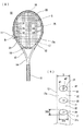
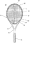
図1乃至図3は第一実施形態のテニスラケットを示し、ラケットフレーム11は、図1(A)に示すように、ヘッド部12、スロート部13、シャフト部14、グリップ部15を連続して形成し、両側のスロート部13にヨーク部16の両端を連結して、ヘッド部12と共に打球面21を囲むガット張架部を形成している。上記ヘッド部12には、ストリングSを挿通する複数のガット穴25をフレーム長手方向に対して垂直な幅方向に貫通させて設けている。詳しくは、ガット穴25は内周部12aに穿設した内側ガット穴20、外周部12bに穿設した外側ガット穴19とからなり、ガット穴20と19とを同一線上に貫通させて設けている。ヘッド部12の外周部12bの表面には、ガット用溝部17を周方向に連続して形成すると共に、粘弾性部材22を装着する領域には幅広の保護材用溝部18を形成している。
1 to 3 show the tennis racket according to the first embodiment. As shown in FIG. 1A, the
ヘッド部12では、打球面21と直交方向の厚みDを28mm、フレーム厚み方向の中央部での断面幅Wを13mm〜18mm(第一実施形態では13mm)とし、打球面21の面積が116平方インチとなるように成形し、上記ガット穴25(外側ガット19および内側ガット穴20)の穴径は3.6mm〜4.0mmの範囲内に設定している。
In the
また、上記粘弾性部材22は、ストリングSを挿通するガット穴22cを貫通させた複数の筒部22aと、該筒部22aを連結する帯部22bとを備えた形状とし、11ナイロンで成形している。
The
上記ラケットフレーム11のヘッド部12を時計面としてトップを12時とすると、3時、9時の領域の内周部12aに、内側ガット穴20の回りに最大深さdを2mmとする複数の凹部31を間隔をあけて形成している。なお、「深さd」とは、凹部31を形成していない箇所の内側面12aと連続する仮想内側面からの深さをいい、以下のすべての実施形態、実施例、比較例についても同様である。
When the
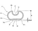
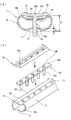
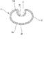
上記凹部31は、図1(B)に示すように、各内側ガット穴20を中心とし、長径31aをフレーム厚みD方向、短径31bをフレーム長手方向とする楕円形状とし、本実施形態では、長径31aを20mm、短径31bを10mmとしている。この凹部31をフレーム長さ方向に垂直に切断した断面形状は、図2に示すように、曲率半径100mmの略直線状となるように形成している。
As shown in FIG. 1 (B), the
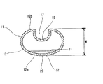
上記ラケットフレーム11のヘッド部12の内周部12aのうち、凹部31を形成していない箇所の内周部12aは、図3に示すように、打球面側の内側に隆起させた湾曲面としている。これにより、凹部31を形成した3時、9時領域の内周部12aには、図1(A)に示すように、相隣接する凹部31の間に湾曲した円弧状の凸部32を形成している。
Of the inner
上記構成からなるテニスラケットでは、ラケットフレーム11の3時、9時領域の内周部12aに、各ガット穴20を中心とする凹部31を形成することにより、3時、9時領域のストリングSの実質可動長さが大となり、打球面21のスイートエリアにおける反発力を高めて、効果的にボールの飛距離を伸ばすことができる。
In the tennis racket having the above-described configuration, a
一方で、凹部31の形状を厚さ方に長く、フレーム長さ方向が短い楕円形状とすることにより、複数の凹部31をフレーム長さ方向に間隔をあけて形成することができ、内周部12aに凹部31と凸部32が交互に形成され、フレーム11の内周長を長くすることができる。従って、成形時の皺の原因である内外周長の差を小さくすることができるため、クラックやひび割れを防止してフレーム11の強度を高めることができる。
また、長径31aをフレーム厚みD方向に配置して、厚みD方向に発生しやすい上記皺を効果的にカバーしながら、フレーム長手方向には短径31bを配置して凹み領域を極力縮小しているため、フレーム11の剛性低下を抑制できる。
さらに、凹部31が楕円形状であることから、図1(B)に示すように、凹部31のフレーム厚みD方向の両端側におけるフレーム長手方向の幅w1が、フレーム厚みD方向の中央部におけるフレーム長手方向の幅w2よりも短くなり、この点からも、フレーム11の内外周長の差を小さくすることができるため、クラック等の原因となる皺の発生を抑制することができる。
さらにまた、凹部31の断面形状を略直線状とすることにより、図2に示すように、内側ガット穴20から凹部31の周縁31cに向かって形状変化を伴わないため、極端な剛性変化による応力集中を抑制して、フレーム11の強度、耐久性を高めることができる。
On the other hand, by forming the
Further, the
Further, since the
Furthermore, since the cross-sectional shape of the
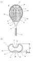
図4(A)(B)は本発明の第二実施形態のテニスラケットを示し、断面幅Wを13mmとするラケットフレーム11のヘッド部12の4箇所のコーナ部、即ち、1時から2時の領域、4時から5時の領域、7時から8時の領域、10時から11時の領域の計4箇所の領域の内周部12aに、各内側ガット穴20を中心とし最大深さdを4mmとする複数の凹部31を間隔をあけて形成している。その他の構成は上記第一実施形態と同様であるため、同一符号を付して説明を省略する。
4A and 4B show a tennis racket according to a second embodiment of the present invention, in which four corner portions of the
本実施形態では、ストリングSの有効長さが最も短くなる上記4領域の内側ガット穴20の周囲に凹部31を形成することにより、ストリングSの有効長さが揃い、ストリング可動面積を効果的に拡大することができる。これにより、反発性が向上して飛距離が伸びると共に、スイートスポットが拡大して操作性も向上する。
また、凹部31のフレーム厚みD方向の断面形状は、図4(B)に示すように円弧形状であるが、曲率半径は50mmであり、剛性変化が極端に表れないため、応力集中を防止して強度低下を抑制できる。
In the present embodiment, the
Further, the cross-sectional shape of the
図5は本発明の第三実施形態のテニスラケットを示し、断面幅Wを13mmとするラケットフレーム11のヘッド部12の12時、6時の領域の内周部12aに、各内側ガット穴20を中心とし最大深さdを4mmとする複数の凹部31を間隔をあけて形成している。上記凹部31の形状および他の構成は上記第一実施形態と同様であるため、同一符号を付して説明を省略する。
上記第三実施形態においても、打球面21のスイートエリアにおける反発力を効果的に高めることができる。
FIG. 5 shows a tennis racket according to a third embodiment of the present invention. Each
Also in the third embodiment, the repulsive force in the sweet area of the
図6(A)(B)は本発明の第四実施形態のテニスラケットの要部を示す。
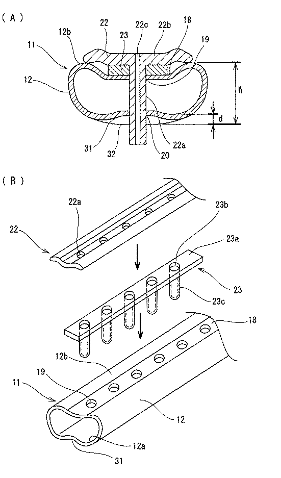
断面幅Wを13mmとするラケットフレーム11のヘッド部12の3時、9時の領域の内周部12aに、各内側ガット穴20を中心とし最大深さdを4mmとする複数の凹部31を間隔をあけて形成している。かつ、凹部31の形成領域と対応する位置の外周部12bの保護材用溝部18に粘弾性部材23を装着し、該粘弾性部材23をフレーム11とグロメットカバー22との間に装着している。
上記粘弾性部材23は、帯部23aに間隔をあけて設けた挿通穴23aの周縁より筒部23cを突出させた形状で、シリコンゴムで成形し、帯板23aの厚さを5mmとしている。該粘弾性部材23に被せるグロメットカバー22には挿通穴23と対応する位置に挿通孔22aをあけている。
6A and 6B show the main part of a tennis racket according to the fourth embodiment of the present invention.
A plurality of
The
本実施形態では、ヘッド部12の3時、9時領域の内側面12aに凹部31を形成することによる反発性向上に加え、同領域の外周部12bに粘弾性部材23を取り付けることにより、粘弾性部材23の弾性を利用して一層反発性を高めることができ、ボールの飛び性能を効果的に上げることができる。同時に、粘弾性部材23により打球時のストリングSとフレームの振動・衝撃を共に吸収して減衰させることができる、よって、良好な打球感が得られ、テニスエルボーの発症も予防することができる。
In the present embodiment, in addition to improving the resilience by forming the
以下の表1に示すとおり、実施例1〜12と比較例1〜3を作製し、テニスラケットの剛性、破壊強度、耐久性、反発係数、振動減衰性について測定し、実打テストも行った。 これら実施例および比較例は、ヘッド部の内周部に穿設されるガット穴20の周りの形状、凹部31の深さ、凹部31の形成位置、フレーム11の断面幅W、および粘弾性部材23の有無または種類等を異ならせた。その他のラケットフレーム11の構成については、いずれの実施例、比較例も上記実施形態のテニスラケットのラケットフレーム11と同一とし、フレーム重量およびフレームバランスは表1に示すとおり設定した。
As shown in Table 1 below, Examples 1 to 12 and Comparative Examples 1 to 3 were prepared, and the tennis racket was measured for rigidity, breaking strength, durability, coefficient of restitution, vibration damping, and an actual hit test was also performed. . In these examples and comparative examples, the shape around the
表1中の複素弾性率は、レオロジ製のFTレオスペクトラーを使用して以下の条件下で測定した 数値のうち、温度5℃で測定した数値を代表して示したものである。
試料:幅5mm×長さ30mm×厚み2mm
試料における変形部位の長さ:20mm(長さ30mmのうち両端5mmを挟持)
初期歪み:10%(2mm)
振幅:12μm
周波数10Hz
温度:0℃〜10℃
モード:引張モード
The complex elastic modulus in Table 1 is representative of the values measured at a temperature of 5 ° C. among the values measured under the following conditions using a FT Rheospectr made by Rheology.
Sample: width 5 mm x length 30 mm x
Length of the deformed part in the sample: 20 mm (5 mm between both ends of 30 mm in length)
Initial strain: 10% (2mm)
Amplitude: 12 μm
10Hz frequency
Temperature: 0 ° C to 10 ° C
Mode: Tensile mode
(実施例1)
凹部31の深さdを2mmとし、フレーム11の断面幅Wを13mmとし、その他の点では上記第一実施形態と同一構成とした。即ち、凹部31は、ヘッド部12の3時、9時の領域に、内側ガット穴20を中心として長径を20mm、短径を10mmとする楕円形状に形成し、凹部31の深さdとフレーム11の断面幅Wとの差を11mmとした。
(実施例2)
上記第一実施形態と同一構成とした。即ち、凹部31の深さdを実施例1と異ならせて4mmとし、フレーム11の断面幅Wを13mmとし、凹部31の深さdとフレーム11の断面幅Wとの差を9mmとした。
(実施例3)
凹部31の深さdを6mmとし、フレーム11の断面幅Wを13mmとし、凹部31の深さdとフレーム11の断面幅Wとの差を7mmとした。その他の点では実施例1と同一構成とした。
(実施例4)
凹部31の深さdは6mmとし、フレーム11の断面幅Wを18mmとし、該凹部31の深さdとフレーム11の断面幅Wとの差を12mmとした。その他の点では実施例1と同一構成とした。
(Example 1)
The depth d of the
(Example 2)
The configuration is the same as that of the first embodiment. That is, the depth d of the
(Example 3)
The depth d of the
Example 4
The depth d of the
(実施例5)
上記第二実施形態と同一構成とした。即ち、フレーム11の断面幅Wを13mmとし、凹部31は、ヘッド部12の1時〜2時、4時〜5時、7時〜8時、10時〜11時の領域に、内側ガット穴20を中心として長径を20mm、短径を10mmとし、深さdを4mmとする楕円形状に形成し、凹部31の深さdとフレーム11の断面幅Wとの差を9mmとした。
(Example 5)
The configuration is the same as that of the second embodiment. That is, the cross-sectional width W of the
(実施例6)
上記第三実施形態と同一構成とした。即ち、フレーム11の断面幅Wを13mmとし、凹部31は、ヘッド部12の12時、6時の領域に、内側ガット穴20を中心として長径を20mm、短径を10mmとし、深さdを4mmとする楕円形状に形成し、凹部31の深さdとフレーム11の断面幅Wとの差を9mmとした。
(Example 6)
The configuration is the same as that of the third embodiment. That is, the cross-sectional width W of the
(実施例7)
上記第四実施形態と同一構成とした。即ち、実施例2と同一構成のフレーム11の3時、9時領域の外面側に粘弾性部材23を取り付けた。該粘弾性部材23は、シリコンゴムで成形し、帯部23aの厚さを5ミリとし、上記条件下で測定された複素弾性率を1.41×10⁷dyn/cm2とした。
(実施例8)
粘弾性部材23をSBRで成形し、上記条件下で測定された複素弾性率を5.07×10⁷dyn/cm2とした。その他の構成は実施例7と同一とした。
(実施例9)
粘弾性部材23を、SBR100部、カーボンブラック40部、硫黄1.5部とを配合して成形し、帯部23aの厚さを2mmとし、上記条件下で測定された複素弾性率を3.86×10⁸dyn/cm2とした。その他の構成は実施例7と同一とした。
(実施例10)
粘弾性部材23を、SBR100部、カーボンブラック40部、硫黄1.5部とを配合して成形し、帯部23aの厚さを5mmとし、上記条件下で測定された複素弾性率を3.86×10⁸dyn/cm2とした。その他の構成は実施例7と同一とした。
(実施例11)
粘弾性部材23を、SBR100部、カーボンブラック40部、硫黄1.5部とを配合して成形し、帯部23aの厚さを8mmとし、上記条件下で測定された複素弾性率を3.86×10⁸dyn/cm2とした。その他の構成は実施例7と同一とした。
(実施例12)
粘弾性部材23を11−ナイロンで成形し、帯部23aの厚さを5mmとし、上記条件下で測定された複素弾性率を1.45×10¹⁰dyn/cm2とした。その他の構成は実施例7と同一とした。
(Example 7)
The configuration is the same as that of the fourth embodiment. That is, the
(Example 8)
The
Example 9
The
(Example 10)
The
(Example 11)
The
(Example 12)
The
(比較例1)
断面幅W13mmのラケットフレーム11に凹部31を形成せず、粘弾性部材23も装着しなかった。
(比較例2)
断面幅W13mmのフレーム11のヘッド部12の3時、9時の領域において、図7に示すように、内側ガット穴20の直径を5mmとし、凹部は形成しなかった。粘弾性部材23も取り付けなかった。
(比較例3)
断面幅W13mmのフレーム11のヘッド部12の内側面12aの全周にわたって、内側ガット穴20を中心とする長径を20mm、短径を10mm、深さdを4mmとする楕円形状の凹部31を形成した。
(Comparative Example 1)
The
(Comparative Example 2)
In the 3 o'clock and 9 o'clock regions of the
(Comparative Example 3)
An
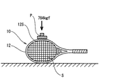
(側圧剛性の測定)
側圧剛性の測定は、図8に示すように、実施例及び比較例のテニスラケット10を横向きで打球面21を垂直方向として、テニスラケットを保持している。この状態で上方のヘッド部12のサイド12sに対して、平板Pにより、784Nの荷重を加えて、荷重時の変位から、バネ定数を算出し、側圧剛性を測定した。
(Measurement of lateral pressure stiffness)
As shown in FIG. 8, the side pressure stiffness is measured by holding the tennis racket with the
(打球面剛性の測定)
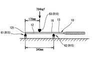
打球面剛性(面外方向の剛性)測定は、図9に示すように、実施例及び比較例のテニスラケット10を水平に配置し、そのヘッド部12のトップ12tを受け治具61(R15)で支持すると共に、トップ12tから340mm離れた位置で、スロート部13の両側からヨーク部16にかけた位置を受け治具62(R15)で支持した。この状態で、受け治具61より受け治具62の方向へ170mm離れた位置に対して、加圧具63(R10)により上方より784Nの荷重を加えて、荷重時の変位から、バネ定数を算出し、打球面剛性を測定した。
(Measurement of ball striking surface stiffness)
As shown in FIG. 9, the ball striking surface stiffness (out-of-plane stiffness) is measured by placing the
(最大反発係数の測定)
反発係数は、図10に示すように、実施例および比較例のテニスラケット10に、ガットを縦60ポンド、横55ポンドの張力で張架し、各テニスラケット10を垂直状態でフリーとなるようにグリップ部15を柔らかく固定し、その打球面21にボール打出機から一定速度V1(30m/sec)でテニスボールを打球面に衝突させ、跳ね返ったボールの速度V2を測定した。反発係数は発射速度V1、反発速度V2の比(V2/V1)であり、反発係数が大きいほどボールの飛びが良いことを示している。
(Measurement of maximum coefficient of restitution)
As shown in FIG. 10, the coefficient of restitution is such that the
(面外1次振動減衰率の測定)
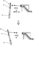
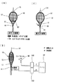
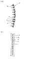
各実施例および比較例のラケットフレーム11を図11(A)に示すようにヘッド部12の上端を紐51で吊り上げ、ヘッド部12とスロート部13との一方の連続点に加速度ピックアップ計53を打球面に垂直に固定した。この状態で、図11(B)に示すように、ヘッド部12とスロート部13の他方の連続点をインパクトハンマー55で加振した。インパクトハンマー55に取り付けられたフォースピックアップ計で計測した入力振動(F)と加速度ピックアップ計53で計測した応答振動(α)をアンプ56A、56Bを介して周波数解析装置57(ヒューレットパッカード社製、ダイナミックシングルアナライザーHP3562A)に入力して解析した。解析で得た周波数領域での伝達関数を求め、テニスラケットの振動数を得た。振動減衰比(ζ)は下式より求め、面外1次振動減衰率とした。各実施例および比較例のラケットフレームについて測定された平均値を上記表1に示す。
(Measurement of out-of-plane primary vibration damping rate)
As shown in FIG. 11 (A), the upper end of the
ζ=(1/2)×(△ω/ωn)
To=Tn×√2
ζ = (1/2) × (Δω / ωn)
To = Tn × √2
(面外2次振動減衰率の測定)
ラケットフレーム11を図12(C)に示すようにヘッド部12上端を紐51で吊り下げ、スロート部13とシャフト部14との連続点に加速度ピックアップ計53を打球面に垂直に固定した。この状態で、加速度ピックアップ計53の裏側のフレーム11をインパクトハンマー55で加振した。そして、面外1次振動減衰率と同等の方法で減衰率を算出し、面外2次振動減衰率とした。各実施例および比較例のラケットフレームについて測定された平均値を上記表1に示す。
(Measurement of out-of-plane secondary vibration attenuation rate)
As shown in FIG. 12C, the upper end of the
(破壊強度の測定)
破壊強度は前記側圧剛性の測定と同一試験条件とし、フレームサイドが破壊するまで荷重をかけ、破壊発生時の荷重を測定した。
(Measurement of fracture strength)
The breaking strength was set to the same test conditions as the measurement of the lateral pressure rigidity, a load was applied until the frame side broke, and the load at the time of occurrence of breaking was measured.
(耐久性の測定)
球速55m/sのボールを打球面21のトップ位置から18cmのところにあてて、フレーム11が破損するかどうかを確認した。
(Durability measurement)
A ball with a ball speed of 55 m / s was placed at a
(実打評価)
ラケットの飛び、コントロール、操作性についてアンケート調査を行った。5点満点で(点が多い程良いと評価)、中・上級者(テニス歴10年以上、現在も週3日以上プレーする条件を満たす女性)43名の採点結果の平均値を表1に示した。
(Actual hit evaluation)
A questionnaire survey was conducted on racket flight, control, and operability. Table 1 shows the average score of 43 middle and advanced players (women who meet the requirements of playing tennis for more than 10 years and currently playing for more than 3 days a week), with a maximum score of 5. Indicated.
表1から確認できるように、フレームの所要箇所に楕円形または真円形の凹部を形成した実施例1〜12のテニスラケットは、いずれも高い剛性、破壊強度、耐久性を備えながら、反発係数も高く、実打評価においても飛びと操作性が共に良いという評価が得られた。また、粘弾性部材を取り付けた実施例7〜12のうち、実施例12を除く各実施例は、振動減衰率も高く、実打評価からも振動・衝撃が少ないことが分かった。
一方、凹部を全く形成しなかった比較例1は、剛性や強度に問題はないが、反発係数が低く、飛び性能が悪いことが分かった。また、ガット穴の穴径を大きくした比較例2や凹部をフレーム全周に形成した比較例3は、反発係数は高いが、剛性、強度、耐久性が低いという結果が得られた。
As can be seen from Table 1, the tennis rackets of Examples 1 to 12 in which the oval or perfect circular recesses are formed in the required portions of the frame all have high rigidity, breaking strength and durability, but also have a coefficient of restitution. High evaluation was obtained that both flying and operability were good in the actual hit evaluation. Moreover, it turned out that each Example except Example 12 among Examples 7-12 which attached the viscoelastic member has a high vibration damping factor, and there are few vibrations and impacts also from actual hit | damage evaluation.
On the other hand, it was found that Comparative Example 1 in which no concave portion was formed had no problem in rigidity and strength, but had a low coefficient of restitution and poor flying performance. Further, Comparative Example 2 in which the diameter of the gut hole was increased and Comparative Example 3 in which the recesses were formed on the entire periphery of the frame had a high coefficient of restitution but a low rigidity, strength, and durability.
また、粘弾性部材の複素弾性率が1.0×10¹⁰dyn/cm2より大きい実施例12の振動減衰率は、粘弾性部材を取り付けていない他の実施例1〜6と殆ど変わらず、実打評価においても振動・衝撃が特に少ないという結果は得られなかった。また、粘弾性部材の帯状基板の厚さが6mm以上の実施例11は、実打評価において操作性が低いという結果が得られた。 Further, the vibration damping rate of Example 12 in which the complex elastic modulus of the viscoelastic member is larger than 1.0 × 10 10 dyn / cm 2 is almost the same as those of other Examples 1 to 6 in which no viscoelastic member is attached, Even in the actual hit evaluation, the result that vibration and impact were particularly small was not obtained. Further, in Example 11 in which the thickness of the band-shaped substrate of the viscoelastic member was 6 mm or more, the result that the operability was low in the actual hit evaluation was obtained.
10 テニスラケット
11 ラケットフレーム
12 ヘッド部
12a 内周部
12b 外周部
18 ガット穴
19 外側ガット穴
20 内側ガット穴
21 打球面
23 粘弾性部材
23a 帯部
31 凹部
31a 長径
31b 短径
23 粘弾性部材
W フレーム断面幅
D フレーム厚み
DESCRIPTION OF
Claims (7)
上記ヘッド部の内周部側には、一部の上記内側ガット穴を中心とする凹部が設けられ、 上記凹部は、打球面と直交するフレーム厚み方向の両端側におけるフレーム長さ方向の寸法が、フレーム厚み方向の中央部におけるフレーム長さ方向の寸法よりも短く設定していることを特徴とするテニスラケット。 A racket frame made of fiber reinforced resin composed of a sleeve of a prepreg laminate is provided, and a gut hole is provided in the head portion surrounding the striking surface of the racquet frame with a gap in the longitudinal direction of the frame. A tennis racket in which an inner gut hole drilled on the inner peripheral side and an outer gut hole drilled on the outer peripheral side are penetrated perpendicularly to the longitudinal direction of the frame,
On the inner peripheral side of the head portion, a recess centered on a part of the inner gut hole is provided, and the recess has dimensions in the frame length direction on both ends in the frame thickness direction orthogonal to the striking surface. The tennis racket is characterized by being set shorter than the dimension in the frame length direction at the center in the frame thickness direction.
Priority Applications (1)
| Application Number | Priority Date | Filing Date | Title |
|---|---|---|---|
| JP2003305347A JP4318989B2 (en) | 2003-08-28 | 2003-08-28 | tennis racket |
Applications Claiming Priority (1)
| Application Number | Priority Date | Filing Date | Title |
|---|---|---|---|
| JP2003305347A JP4318989B2 (en) | 2003-08-28 | 2003-08-28 | tennis racket |
Publications (2)
| Publication Number | Publication Date |
|---|---|
| JP2005073785A true JP2005073785A (en) | 2005-03-24 |
| JP4318989B2 JP4318989B2 (en) | 2009-08-26 |
Family
ID=34408792
Family Applications (1)
| Application Number | Title | Priority Date | Filing Date |
|---|---|---|---|
| JP2003305347A Expired - Fee Related JP4318989B2 (en) | 2003-08-28 | 2003-08-28 | tennis racket |
Country Status (1)
| Country | Link |
|---|---|
| JP (1) | JP4318989B2 (en) |
Cited By (1)
| Publication number | Priority date | Publication date | Assignee | Title |
|---|---|---|---|---|
| US20220134190A1 (en) * | 2019-03-08 | 2022-05-05 | Yonex Co., Ltd. | Grommet and racket |
-
2003
- 2003-08-28 JP JP2003305347A patent/JP4318989B2/en not_active Expired - Fee Related
Cited By (2)
| Publication number | Priority date | Publication date | Assignee | Title |
|---|---|---|---|---|
| US20220134190A1 (en) * | 2019-03-08 | 2022-05-05 | Yonex Co., Ltd. | Grommet and racket |
| US12594468B2 (en) * | 2019-03-08 | 2026-04-07 | Yonex Co., Ltd. | Grommet and racket |
Also Published As
| Publication number | Publication date |
|---|---|
| JP4318989B2 (en) | 2009-08-26 |
Similar Documents
| Publication | Publication Date | Title |
|---|---|---|
| JP4143725B2 (en) | tennis racket | |
| JP3970865B2 (en) | Racket frame | |
| JP4041031B2 (en) | Racket frame | |
| JP4049631B2 (en) | Racket frame | |
| JP4318989B2 (en) | tennis racket | |
| JP4778216B2 (en) | racket | |
| JP3734008B2 (en) | Racket frame | |
| JP2000061004A (en) | tennis racket | |
| JP2005065842A (en) | Racket frame | |
| JP3738276B2 (en) | Tennis racket frame | |
| JP4737360B2 (en) | Racket frame | |
| JP3820215B2 (en) | tennis racket | |
| JP4362743B2 (en) | Racket frame | |
| JP4064763B2 (en) | racket | |
| JP2004357982A (en) | tennis racket | |
| JP4456379B2 (en) | tennis racket | |
| JP2004073507A (en) | racket | |
| JP4444429B2 (en) | Soft tennis racket frame | |
| JP3508910B2 (en) | Racket frame | |
| JP2005328925A (en) | Racket frame | |
| JP4218871B2 (en) | String protector and tennis racket provided with the string protector | |
| JP4371399B2 (en) | Racket frame and vibration damping material attached to the racket frame | |
| JP2002078834A (en) | Golf club shaft | |
| JP4097189B2 (en) | racket | |
| JP2007054232A (en) | racket |
Legal Events
| Date | Code | Title | Description |
|---|---|---|---|
| A711 | Notification of change in applicant |
Free format text: JAPANESE INTERMEDIATE CODE: A711 Effective date: 20050523 |
|
| RD02 | Notification of acceptance of power of attorney |
Free format text: JAPANESE INTERMEDIATE CODE: A7422 Effective date: 20050603 |
|
| A621 | Written request for application examination |
Free format text: JAPANESE INTERMEDIATE CODE: A621 Effective date: 20060322 |
|
| A977 | Report on retrieval |
Free format text: JAPANESE INTERMEDIATE CODE: A971007 Effective date: 20081217 |
|
| A131 | Notification of reasons for refusal |
Free format text: JAPANESE INTERMEDIATE CODE: A131 Effective date: 20090113 |
|
| A521 | Written amendment |
Free format text: JAPANESE INTERMEDIATE CODE: A523 Effective date: 20090311 |
|
| TRDD | Decision of grant or rejection written | ||
| A01 | Written decision to grant a patent or to grant a registration (utility model) |
Free format text: JAPANESE INTERMEDIATE CODE: A01 Effective date: 20090526 |
|
| A01 | Written decision to grant a patent or to grant a registration (utility model) |
Free format text: JAPANESE INTERMEDIATE CODE: A01 |
|
| A61 | First payment of annual fees (during grant procedure) |
Free format text: JAPANESE INTERMEDIATE CODE: A61 Effective date: 20090527 |
|
| FPAY | Renewal fee payment (event date is renewal date of database) |
Free format text: PAYMENT UNTIL: 20120605 Year of fee payment: 3 |
|
| R150 | Certificate of patent or registration of utility model |
Ref document number: 4318989 Country of ref document: JP Free format text: JAPANESE INTERMEDIATE CODE: R150 Free format text: JAPANESE INTERMEDIATE CODE: R150 |
|
| FPAY | Renewal fee payment (event date is renewal date of database) |
Free format text: PAYMENT UNTIL: 20120605 Year of fee payment: 3 |
|
| FPAY | Renewal fee payment (event date is renewal date of database) |
Free format text: PAYMENT UNTIL: 20130605 Year of fee payment: 4 |
|
| R250 | Receipt of annual fees |
Free format text: JAPANESE INTERMEDIATE CODE: R250 |
|
| R250 | Receipt of annual fees |
Free format text: JAPANESE INTERMEDIATE CODE: R250 |
|
| R250 | Receipt of annual fees |
Free format text: JAPANESE INTERMEDIATE CODE: R250 |
|
| R250 | Receipt of annual fees |
Free format text: JAPANESE INTERMEDIATE CODE: R250 |
|
| R250 | Receipt of annual fees |
Free format text: JAPANESE INTERMEDIATE CODE: R250 |
|
| R250 | Receipt of annual fees |
Free format text: JAPANESE INTERMEDIATE CODE: R250 |
|
| R250 | Receipt of annual fees |
Free format text: JAPANESE INTERMEDIATE CODE: R250 |
|
| R250 | Receipt of annual fees |
Free format text: JAPANESE INTERMEDIATE CODE: R250 |
|
| LAPS | Cancellation because of no payment of annual fees |