JP2005073746A - Ultrasonic treatment apparatus - Google Patents
Ultrasonic treatment apparatus Download PDFInfo
- Publication number
- JP2005073746A JP2005073746A JP2003304709A JP2003304709A JP2005073746A JP 2005073746 A JP2005073746 A JP 2005073746A JP 2003304709 A JP2003304709 A JP 2003304709A JP 2003304709 A JP2003304709 A JP 2003304709A JP 2005073746 A JP2005073746 A JP 2005073746A
- Authority
- JP
- Japan
- Prior art keywords
- ultrasonic
- ultrasonic transducer
- cover member
- flexible sheath
- signal cable
- Prior art date
- Legal status (The legal status is an assumption and is not a legal conclusion. Google has not performed a legal analysis and makes no representation as to the accuracy of the status listed.)
- Granted
Links
- 238000009210 therapy by ultrasound Methods 0.000 title claims abstract description 46
- 238000011282 treatment Methods 0.000 claims abstract description 61
- 230000001112 coagulating effect Effects 0.000 abstract description 2
- 230000003902 lesion Effects 0.000 abstract 1
- 238000005452 bending Methods 0.000 description 10
- 238000005286 illumination Methods 0.000 description 5
- 230000023597 hemostasis Effects 0.000 description 4
- 239000010410 layer Substances 0.000 description 4
- 230000010355 oscillation Effects 0.000 description 4
- 239000000523 sample Substances 0.000 description 4
- 210000000078 claw Anatomy 0.000 description 3
- 230000015271 coagulation Effects 0.000 description 3
- 238000005345 coagulation Methods 0.000 description 3
- 238000010586 diagram Methods 0.000 description 3
- 230000002093 peripheral effect Effects 0.000 description 3
- 206010028980 Neoplasm Diseases 0.000 description 2
- 239000004020 conductor Substances 0.000 description 2
- 238000004945 emulsification Methods 0.000 description 2
- 230000020169 heat generation Effects 0.000 description 2
- 238000000034 method Methods 0.000 description 2
- 238000003466 welding Methods 0.000 description 2
- 210000004204 blood vessel Anatomy 0.000 description 1
- 239000011248 coating agent Substances 0.000 description 1
- 238000000576 coating method Methods 0.000 description 1
- 230000000694 effects Effects 0.000 description 1
- 230000005611 electricity Effects 0.000 description 1
- 238000005516 engineering process Methods 0.000 description 1
- 239000011810 insulating material Substances 0.000 description 1
- 239000002184 metal Substances 0.000 description 1
- 238000012986 modification Methods 0.000 description 1
- 230000004048 modification Effects 0.000 description 1
- 239000011241 protective layer Substances 0.000 description 1
- 238000010298 pulverizing process Methods 0.000 description 1
- 230000003014 reinforcing effect Effects 0.000 description 1
- 238000005245 sintering Methods 0.000 description 1
Images

Classifications
-
- A—HUMAN NECESSITIES
- A61—MEDICAL OR VETERINARY SCIENCE; HYGIENE
- A61B—DIAGNOSIS; SURGERY; IDENTIFICATION
- A61B17/00—Surgical instruments, devices or methods
- A61B17/22—Implements for squeezing-off ulcers or the like on inner organs of the body; Implements for scraping-out cavities of body organs, e.g. bones; for invasive removal or destruction of calculus using mechanical vibrations; for removing obstructions in blood vessels, not otherwise provided for
- A61B17/22004—Implements for squeezing-off ulcers or the like on inner organs of the body; Implements for scraping-out cavities of body organs, e.g. bones; for invasive removal or destruction of calculus using mechanical vibrations; for removing obstructions in blood vessels, not otherwise provided for using mechanical vibrations, e.g. ultrasonic shock waves
- A61B17/22012—Implements for squeezing-off ulcers or the like on inner organs of the body; Implements for scraping-out cavities of body organs, e.g. bones; for invasive removal or destruction of calculus using mechanical vibrations; for removing obstructions in blood vessels, not otherwise provided for using mechanical vibrations, e.g. ultrasonic shock waves in direct contact with, or very close to, the obstruction or concrement
- A61B17/2202—Implements for squeezing-off ulcers or the like on inner organs of the body; Implements for scraping-out cavities of body organs, e.g. bones; for invasive removal or destruction of calculus using mechanical vibrations; for removing obstructions in blood vessels, not otherwise provided for using mechanical vibrations, e.g. ultrasonic shock waves in direct contact with, or very close to, the obstruction or concrement the ultrasound transducer being inside patient's body at the distal end of the catheter
-
- A—HUMAN NECESSITIES
- A61—MEDICAL OR VETERINARY SCIENCE; HYGIENE
- A61B—DIAGNOSIS; SURGERY; IDENTIFICATION
- A61B17/00—Surgical instruments, devices or methods
- A61B17/32—Surgical cutting instruments
- A61B17/320016—Endoscopic cutting instruments, e.g. arthroscopes, resectoscopes
-
- A—HUMAN NECESSITIES
- A61—MEDICAL OR VETERINARY SCIENCE; HYGIENE
- A61B—DIAGNOSIS; SURGERY; IDENTIFICATION
- A61B17/00—Surgical instruments, devices or methods
- A61B17/22—Implements for squeezing-off ulcers or the like on inner organs of the body; Implements for scraping-out cavities of body organs, e.g. bones; for invasive removal or destruction of calculus using mechanical vibrations; for removing obstructions in blood vessels, not otherwise provided for
- A61B17/22004—Implements for squeezing-off ulcers or the like on inner organs of the body; Implements for scraping-out cavities of body organs, e.g. bones; for invasive removal or destruction of calculus using mechanical vibrations; for removing obstructions in blood vessels, not otherwise provided for using mechanical vibrations, e.g. ultrasonic shock waves
- A61B2017/22027—Features of transducers
-
- A—HUMAN NECESSITIES
- A61—MEDICAL OR VETERINARY SCIENCE; HYGIENE
- A61B—DIAGNOSIS; SURGERY; IDENTIFICATION
- A61B17/00—Surgical instruments, devices or methods
- A61B17/32—Surgical cutting instruments
- A61B17/320068—Surgical cutting instruments using mechanical vibrations, e.g. ultrasonic
- A61B2017/320089—Surgical cutting instruments using mechanical vibrations, e.g. ultrasonic node location
-
- A—HUMAN NECESSITIES
- A61—MEDICAL OR VETERINARY SCIENCE; HYGIENE
- A61B—DIAGNOSIS; SURGERY; IDENTIFICATION
- A61B17/00—Surgical instruments, devices or methods
- A61B17/32—Surgical cutting instruments
- A61B17/320068—Surgical cutting instruments using mechanical vibrations, e.g. ultrasonic
- A61B17/320092—Surgical cutting instruments using mechanical vibrations, e.g. ultrasonic with additional movable means for clamping or cutting tissue, e.g. with a pivoting jaw
- A61B2017/320094—Surgical cutting instruments using mechanical vibrations, e.g. ultrasonic with additional movable means for clamping or cutting tissue, e.g. with a pivoting jaw additional movable means performing clamping operation
-
- A—HUMAN NECESSITIES
- A61—MEDICAL OR VETERINARY SCIENCE; HYGIENE
- A61B—DIAGNOSIS; SURGERY; IDENTIFICATION
- A61B90/00—Instruments, implements or accessories specially adapted for surgery or diagnosis and not covered by any of the groups A61B1/00 - A61B50/00, e.g. for luxation treatment or for protecting wound edges
- A61B90/36—Image-producing devices or illumination devices not otherwise provided for
- A61B90/37—Surgical systems with images on a monitor during operation
- A61B2090/373—Surgical systems with images on a monitor during operation using light, e.g. by using optical scanners
Landscapes
- Health & Medical Sciences (AREA)
- Surgery (AREA)
- Engineering & Computer Science (AREA)
- Life Sciences & Earth Sciences (AREA)
- Biomedical Technology (AREA)
- Molecular Biology (AREA)
- Vascular Medicine (AREA)
- Orthopedic Medicine & Surgery (AREA)
- Mechanical Engineering (AREA)
- Heart & Thoracic Surgery (AREA)
- Medical Informatics (AREA)
- Nuclear Medicine, Radiotherapy & Molecular Imaging (AREA)
- Animal Behavior & Ethology (AREA)
- General Health & Medical Sciences (AREA)
- Public Health (AREA)
- Veterinary Medicine (AREA)
- Surgical Instruments (AREA)
- Ultra Sonic Daignosis Equipment (AREA)
Abstract
Description
本発明は、内視鏡とともに用いられる超音波処置装置に関する。 The present invention relates to an ultrasonic treatment apparatus used with an endoscope.
内視鏡用超音波処置具が、[特許文献1]に開示されている。これは、処置部先端にループを持つ超音波振動自在要素としての可撓性ワイヤを備え、アクチュエータを操作することにより前記ループを開放構造と閉鎖構造との間で移動自在としている。前記可撓性ワイヤを内視鏡のチャンネルに挿入し、操作部に内蔵された超音波振動子から発生する超音波振動を可撓性ワイヤに伝達させて被検体の処置を行う。たとえば、ポリープ等の切除に最適である。 An ultrasonic treatment instrument for an endoscope is disclosed in [Patent Document 1]. This is provided with a flexible wire as an ultrasonic vibration free element having a loop at the distal end of the treatment portion, and the loop is movable between an open structure and a closed structure by operating an actuator. The flexible wire is inserted into the channel of the endoscope, and ultrasonic vibration generated from the ultrasonic vibrator built in the operation unit is transmitted to the flexible wire to treat the subject. For example, it is most suitable for excision of polyps and the like.
一方、[特許文献2]に開示される超音波手術装置は、先端にブレード(刃)を取付けた超音波振動子を保持棒に固定し、これらをトラカールに挿入してなるものであって、先端ブレードにより被検体の処置を行う。前記超音波振動子と手術用ブレードを一体化し、使い捨てに適した構成であるとともに、超音波損失が大幅に減るので無駄な発熱が減り、手術操作の自由度が大幅に向上する、とある。
しかしながら、[特許文献1]に開示される技術では、処置部がループ形状であるため、ループより大きい腫瘍を切除することができないうえに、突出していない腫瘍、血管の切断・止血等は処置できず、適用範囲が極めて限られている。そして、超音波振動子に発生する超音波振動を長尺の可撓性プローブに伝達させるので、発熱などで振動エネルギーが損失し、先端処置部では所望の振動振幅を得られない可能性もある。 However, in the technique disclosed in [Patent Document 1], since the treatment portion has a loop shape, it is not possible to excise a tumor larger than the loop, and it is possible to treat a tumor that does not protrude, blood vessel cutting and hemostasis, and the like. However, the scope of application is extremely limited. Then, since the ultrasonic vibration generated in the ultrasonic transducer is transmitted to the long flexible probe, vibration energy is lost due to heat generation, etc., and there is a possibility that a desired vibration amplitude cannot be obtained in the distal treatment section. .
さらに、軟性内視鏡と組み合わせて使用する可撓性プローブは、内視鏡を湾曲させた状態で超音波振動を行うため、軟性内視鏡の先端湾曲部に対応した部分以外においても超音波プローブにかかる振動的応力が大きく、耐性が劣るうえに、チャンネル内径を傷つける恐れがある。 Furthermore, since the flexible probe used in combination with the flexible endoscope performs ultrasonic vibration while the endoscope is curved, the ultrasonic probe is also used in a portion other than the portion corresponding to the tip bending portion of the flexible endoscope. The vibration stress applied to the probe is large, the resistance is inferior, and the channel inner diameter may be damaged.
これに対して、[特許文献2]に開示される技術では、前記[特許文献1]の不具合を解決できる可能性はあるが、保持棒は剛体であって可撓性を備えていないので、軟性鏡では使用できない。また、保持棒は超音波振動子における超音波振動の節位置以外の部分に接続されているので、振動エネルギーが損失して、先端ブレードに所望の振動振幅が得られない。 On the other hand, in the technology disclosed in [Patent Document 2], there is a possibility that the problem of [Patent Document 1] may be solved, but the holding rod is a rigid body and does not have flexibility. Cannot be used with flexible endoscopes. Further, since the holding rod is connected to a portion other than the ultrasonic vibration node position in the ultrasonic vibrator, vibration energy is lost, and a desired vibration amplitude cannot be obtained in the tip blade.
仮に、前記保持棒を可撓性のガイドワイヤに換えた場合でも、患者に対する安全性に大いに問題がある。すなわち、超音波振動子に使用される圧電素子、もしくは磁歪素子は人体に有害である場合が多いが、[特許文献2]では基本的に超音波振動子が被検体に対して露出する構成になっている。 Even if the holding rod is replaced with a flexible guide wire, there is a great problem in safety for the patient. That is, the piezoelectric element or magnetostrictive element used in the ultrasonic transducer is often harmful to the human body, but [Patent Document 2] basically has a configuration in which the ultrasonic transducer is exposed to the subject. It has become.
本発明は、上述した点に鑑みてなされたものであり、その目的とするところは、内視鏡とともに用いて被検体の管腔部に挿入し、内視鏡による患部の観察をしながら、超音波振動による生体組織の切開・凝固処置等が可能な超音波処置装置を提供しようとするものである。 The present invention has been made in view of the above-described points, and its purpose is to use it together with an endoscope and insert it into the lumen of a subject while observing the affected area with an endoscope. It is an object of the present invention to provide an ultrasonic treatment apparatus capable of incising and coagulating biological tissue by ultrasonic vibration.
請求項1の発明は、生体組織を処置するための超音波振動を発生可能な超音波振動子をカバー部材で覆い、このカバー部材に中空の可撓性シースの一端を連結し、カバー部材に覆われた超音波振動子に信号ケーブルの一端を接続して可撓性シースの内部に挿通し、信号ケーブルの他端に超音波駆動手段を接続し、可撓性シースの他端部に操作者の操作に応じてカバー部材とともに超音波振動子を変位可能な操作部を具備する。 According to the first aspect of the present invention, an ultrasonic transducer capable of generating ultrasonic vibration for treating living tissue is covered with a cover member, and one end of a hollow flexible sheath is connected to the cover member, and the cover member is connected to the cover member. Connect one end of the signal cable to the covered ultrasonic transducer and insert it into the flexible sheath, connect the ultrasonic drive to the other end of the signal cable, and operate the other end of the flexible sheath And an operation unit capable of displacing the ultrasonic transducer together with the cover member in accordance with the operation of the person.
請求項2の発明は、生体組織を処置するための超音波振動を発生可能な超音波振動子をカバー部材で覆い、カバー部材の後方に中空の可撓性シースの一端を連結し、カバー部材に覆われた超音波振動子に信号ケーブルの一端を接続して可撓性シース内部に挿通し、信号ケーブルの他端に超音波駆動手段に接続可能なコネクタ手段を設け、可撓性シースの他端部に操作者の操作に応じてカバー部材とともに超音波振動子を変位可能な操作部を具備する。
The invention according to
請求項3の発明は、生体組織を処置するための超音波振動を発生可能な超音波振動子をカバー部材で覆い、カバー部材の後方に中空の可撓性シースの一端を連結し、超音波振動子に信号ケーブルの一端を接続して可撓性シースの内部に挿通し、信号ケーブルの他端を取出し可能なケーブル取出し口を有し、可撓性シースの他端に操作者の操作に応じてカバー部材とともに超音波振動子を変位可能な操作部を備え、ケーブル取出し口から取出された信号ケーブルの他端に超音波駆動手段を接続して超音波振動子を駆動する駆動信号を発生させる。 According to a third aspect of the present invention, an ultrasonic transducer capable of generating ultrasonic vibration for treating living tissue is covered with a cover member, one end of a hollow flexible sheath is connected to the rear of the cover member, One end of the signal cable is connected to the vibrator and inserted into the flexible sheath, and the other end of the signal cable can be taken out, and the other end of the flexible sheath can be operated by the operator. Correspondingly, an operation unit that can displace the ultrasonic transducer along with the cover member is provided, and an ultrasonic drive means is connected to the other end of the signal cable taken out from the cable outlet to generate a drive signal for driving the ultrasonic transducer. Let
請求項4の発明は、生体組織を処置するための超音波振動を発生可能な超音波振動子をカバー部材で覆い、カバー部材の後方に中空の可撓性シースの一端を連結して内部に超音波振動子から延出された信号ケーブルを挿通可能とし、可撓性シースの他端に操作者の操作に応じてカバー部材とともに超音波振動子を変位可能な操作部を設け、信号ケーブルの端部を取出し可能なケーブル取出し口を操作部に設け、ケーブル取出し口から取出された信号ケーブルの端部に超音波駆動手段に接続可能なコネクタ手段を具備する。
In the invention of
請求項5の発明は、生体組織を処置するための超音波振動を発生可能な超音波振動子を有し、超音波振動子を駆動するための駆動装置に接続可能な超音波処置装置において、超音波振動子をカバー部材で覆い、カバー部材の後方に中空の可撓性シースの一端を連結して内部に超音波振動子から延出される信号ケーブルを挿通し、信号ケーブルを駆動装置に接続するためのケーブル取出し口を有し、可撓性シースの他端に操作者の操作に応じてカバー部材とともに超音波振動子を変位可能な操作部を具備する。
The invention according to
請求項1ないし請求項5の発明によれば、振動子カバーに覆われた超音波振動子および可撓性シースを内視鏡のチャンネル内に挿通して、超音波振動子先端を内視鏡先端から突没操作できるとともに、超音波振動による被検体の切開・凝固などができる。 According to the first to fifth aspects of the present invention, the ultrasonic transducer and the flexible sheath covered with the transducer cover are inserted into the channel of the endoscope, and the tip of the ultrasonic transducer is inserted into the endoscope. In addition to being able to project and retract from the tip, incision and coagulation of the subject can be performed by ultrasonic vibration.
請求項6の発明は、生体組織を処置するための超音波振動を発生可能な超音波振動子をカバー部材で覆い、カバー部材の後方に中空の可撓性シースの一端を連結し、カバー部材に覆われる超音波振動子に信号ケーブルの一端を接続して可撓性シースの内部に挿通させ、信号ケーブルの他端に超音波振動子を駆動する駆動信号を発生するための超音波駆動手段を接続し、可撓性シースの他端部に操作者の操作に応じてカバー部材とともに超音波振動子を変位可能な操作部を設け、カバー部材に鉗子部材を回動自在に設け、鉗子部材に操作ワイヤの一端を接続して可撓性シースの内部に挿通させ、操作ワイヤの他端に操作部に対して移動可能なハンドル手段を具備する。 According to the sixth aspect of the present invention, an ultrasonic transducer capable of generating ultrasonic vibration for treating a living tissue is covered with a cover member, and one end of a hollow flexible sheath is connected to the rear of the cover member. One end of the signal cable is connected to the ultrasonic transducer covered with the ultrasonic wave, and is inserted into the flexible sheath, and an ultrasonic drive means for generating a drive signal for driving the ultrasonic transducer at the other end of the signal cable An operation portion capable of displacing the ultrasonic transducer together with the cover member according to the operation of the operator is provided at the other end portion of the flexible sheath, and the forceps member is rotatably provided on the cover member. One end of the operation wire is connected to the inside of the flexible sheath, and a handle means is provided at the other end of the operation wire that is movable with respect to the operation portion.
請求項7の発明は、生体組織を処置するための超音波振動を発生可能な超音波振動子をカバー部材で覆い、カバー部材の後方に中空の可撓性シースの一端を連結し、カバー部材に覆われた超音波振動子に信号ケーブルの一端を接続して可撓性シースの内部に挿通し、信号ケーブルの他端に超音波駆動手段に接続可能なコネクタ手段を設け、可撓性シースの他端部に操作者の操作に応じてカバー部材とともに超音波振動子を変位可能な操作部を設け、カバー部材に鉗子部材を回動自在に設け、鉗子部材に操作ワイヤの一端を接続して可撓性シースの内部に挿通し、操作ワイヤの他端に操作部に対して移動可能なハンドル手段を具備する。
According to the invention of
請求項8の発明は、請求項6および請求項7のいずれかに記載の前記鉗子部材は、超音波振動子の先端部との間に生体組織を挟持するように支持されている。 According to an eighth aspect of the present invention, the forceps member according to any one of the sixth and seventh aspects is supported so as to sandwich a living tissue between a distal end portion of an ultrasonic transducer.
請求項9の発明は、請求項6および請求項7のいずれかに記載の前記鉗子部材は一対備えられ、超音波振動子の先端部に対向する部位の生体組織を挟持するように支持されている。 According to a ninth aspect of the present invention, a pair of the forceps members according to any one of the sixth and seventh aspects is provided, and is supported so as to sandwich a living tissue at a portion facing the tip of the ultrasonic transducer. Yes.
請求項6ないし請求項9の発明によれば、超音波振動子の先端部に対向した状態で鉗子部材で生体組織を確実に挟持し、超音波処置が行える。 According to the sixth to ninth aspects of the present invention, ultrasonic treatment can be performed by securely holding the living tissue with the forceps member in a state of facing the distal end portion of the ultrasonic transducer.
本発明によれば、内視鏡とともに用いて被検体の管腔部に挿入され、内視鏡による患部の観察を行いながら、超音波振動による生体組織の切開・凝固処置等ができるという効果を奏する。 Advantageous Effects of Invention According to the present invention, it is possible to perform an incision / coagulation treatment of a living tissue by ultrasonic vibration while being used together with an endoscope and inserted into a lumen portion of a subject and observing an affected part with an endoscope. Play.
図1〜図17は本発明の実施例1に係る。図1は超音波処置装置を備えた内視鏡の全体構成を示す図、図2は図1のA部を拡大した断面図、図3(A)は超音波処置装置と内視鏡の先端の斜視図、図3(B)はホーン先端の正面図、図4はホーンのフランジ部と振動子カバーとの嵌合い部の断面図、図5は図2のB−B’線に沿う断面図、図6〜図8は互いに異なる超音波振動子の構成を示す図、図9は振動子カバーの変形した断面図、図10はさらに異なる超音波振動子の構成を示す図、図11(A)(B)は積層圧電体の構成を示す斜視図、図12〜図14は屈曲(横)振動する超音波振動子の構成を示す断面図と斜視図、図15はねじり振動する超音波振動子の構成を示す断面図、図16はねじり振動する超音波振動子の構成を示す斜視図、図17はねじり圧電素子の構成を示す斜視図である。
1 to 17 relate to
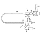
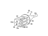
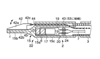
図1に示す内視鏡1は、手元操作部1Aと、この手元操作部1Aに連設される可撓管部1Bと、この可撓管部1Bの先端に一体に設けられる先端部1Cとから構成される。図2および図3(A)に示すように、先端部1C内部には、観察系レンズ(観察手段)13と、照明系レンズ(照明手段)50が収容固定される。先端部1Cから可撓管部1Bに亘って、イメージガイド14および複数の湾曲駒12が収容され、これら湾曲駒12によって可撓管部1Bが湾曲変形自在となっている。
The
手元操作部1Aから可撓管部1Bを介して先端部1Cまで、チャンネル23が収容される。このチャンネル23には手元操作部1Aから鉗子等の処置具が挿入可能であるとともに、後述する超音波処置装置2を構成する超音波振動子22が挿入可能である。手元操作部1Aには、処置具あるいは超音波振動子22を外部から出し入れ可能な口金部4が設けられる。さらに、手元操作部1Aには、図示しない光源およびビデオに接続されるビデオ端子10が設けられる。
The
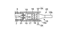
図1、図2および図3(A)に示す内視鏡1の観察下で超音波による処置を行う機能を備えた超音波処置装置2は、超音波振動子22と、この超音波振動子22を駆動する駆動信号を送る信号ケーブル7と、超音波振動子22に接続され、かつ超音波振動子22から延出された信号ケーブル7を内部に挿通する中空の可撓性シース3と、この可撓性シース3の端部に設けられた操作部6と、信号ケーブル7の端部を取出し可能な信号ケーブル取出口5と、信号ケーブル7の一端に設けられるコネクタ(コネクタ手段)8と、このコネクタ8に着脱自在に接続される超音波発振装置(超音波駆動手段)9から構成される。
The
前記可撓性シース3は、内層3aと外層3bとの2重構造であり、これらの間に補強部材を介在あるいは埋設する2重チューブシースが用いられる。前記超音波振動子22の先端部と可撓性シース3の外径寸法は前記チャンネル23の内径寸法よりも小さく形成され、これら超音波振動子22と可撓性シース3はチャンネル23内に挿通可能となっている。そして、可撓性シース3の全長はチャンネル23全長よりも若干長く形成されていて、可撓性シース3の端部に設けられる前記操作部6を前後方向に移動操作することで、内視鏡先端部1Cに対して超音波振動子22の突没移動が可能である。
The
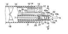
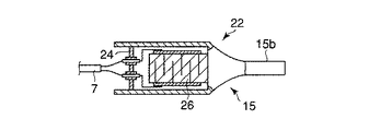
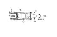
図2に示す前記超音波振動子22は、振動の節に位置するフランジ部15aおよび先端面bが振動の腹に位置する先端処置部15bを有するホーン15と、このホーン15のフランジ部15a側端面に取付けられ軸方向に沿って縦振動する圧電素子16と、この圧電素子16をホーン15端面に強固に取付け固定する金属部材である裏打板17を備えている。
The
さらに、超音波振動子22は、ホーン15以外の超音波振動子22全体を覆う円筒形の振動子カバー18と、圧電素子16における−電極49aおよび+電極49bに接続され圧電素子16に電気を供給する導線19と、これら導線19と接続され振動子カバー(カバー部材)18後端に設けられる2つの孔にそれぞれ挿入固定される導電ピン20と、各導電ピン20の周囲を被覆し振動子カバー18後端の孔との隙間を埋める絶縁材からなる絶縁被覆21を備えている。
Further, the
前記振動子カバー18に可撓性シース3が接続されていて、これら振動子カバー18と可撓性シース3の外径寸法は互いに略同一に設定されチャンネル23内に挿通可能であることは、先に説明したとおりである。前記導電ピン20の一端に信号ケーブル7が接続されていて、この信号ケーブル7は可撓性シース3内に挿通される。そして、信号ケーブル7はケーブル取出し口5から延出して超音波発振装置9に接続され、超音波振動子22は前記超音波発振装置9が発生する駆動信号を受けるようになっている。
The
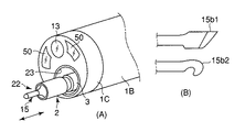
前記ホーン15の先端処置部15bの形状は、図3(B)に示すようにメス型15b1であったり、フック型15b2であったり、その他多様な形状を選択できる。図2に示すように、ホーン15において、振動の腹である先端処置部15bの先端面bは、振動子カバー18に固定される振動の節であるフランジ部15aから 1/4 波長の距離に位置するように設定されている。
The
つぎに、図4〜図8を用いて、振動子カバー18に対するホーン15の取付け構造について説明する。
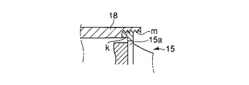
図4に示すように、フランジ部15aの周端部分をホーン15の軸方向に沿ってある程度長く成形し、この周面に軸方向に沿ってねじ部kを設け、振動子カバー18の先端部内周面に設けられるねじ孔mに螺合することにより、ホーン15のフランジ部15aを振動子カバー18に取付け固定できる。
Next, a structure for attaching the
As shown in FIG. 4, the peripheral end portion of the
あるいは、フランジ部15aと振動子カバー18の互いに嵌め込まれる周面をレーザー等で溶接して、ホーン15を振動子カバー18に取付け固定してもよい。この場合、図5に示すように、互いの嵌合面一部を平坦面とすることにより、溶接時の位置決めが容易になる。あるいは、図6に示すように、振動子カバー18とフランジ部15aに取付けねじ54を挿通して取付け固定してもよい。
Alternatively, the
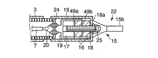
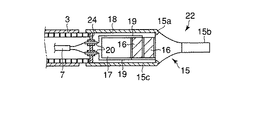
あるいは、図7に示すように、振動子カバー18の先端を折曲げて、この折曲げ部18aをホーン15と圧電素子16との間に挟持する構成としてもよい。そして、ホーン15、振動子カバー18、圧電素子16、電極49a、49bおよび裏打板17を埋込ボルト25で固定することにより、超音波振動子22の構成部品の締結と、振動子カバー18の固定を一本のボルトで行うことができる。あるいは、図8に示すように、ホーン15の後端部に円筒状のカバー部15cを一体に設けることで、ホーン15と振動子カバー18の機能を一部品に集約させ構造の単純化を図ることもできる。その際、ホーン15のカバー部15cの後端は導電ピン20挿通用の2つの孔を有する遮蔽板24で塞がれる。
Alternatively, as shown in FIG. 7, the tip of the
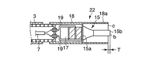
なお、手技によってはホーン15の先端処置部15bを所定深さの範囲内で処置したい場合がある。このような要求を満たすために、図9に示すように、振動子カバー18をホーン15のフランジ部15aよりもさらに先端処置部15b側に延出する延出部18aを一体に設ける。この振動子カバー延出部18aの先端縁cとホーン15の先端処置部15bの先端面bとの距離Tを適宜調整することで、常に所望の処置深さを保持できる。
Depending on the procedure, it may be desired to treat the
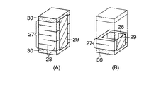
これまで説明したように超音波振動子22は、ホーン15と、圧電素子16と、電極49a,49bおよび裏打板17を、ボルトで一体に締結固定するボルト締めランジュバン型振動子が一般的であるが、図10に示すように、積層圧電体26をホーン15に接着する超音波振動子22の構成とすれば、さらなる構造の単純化を図れる。前記積層圧電体26は、図11(A)および(B)に示すように、圧電層27と、内部電極28と、外部電極29と、絶縁保護層30が一体に焼結形成されたものであり、外部電極29への電気信号により超音波振動する。
As described above, the
なお、上述の超音波振動子22は軸方向に沿って振動する縦振動であるが、処置対象の形状や、状態によっては縦以外の振動が有効な場合もある。図12〜図14に示す超音波振動子22は、軸方向に対して垂直な方向に振動する屈曲(横)振動を発生させることができる。
The
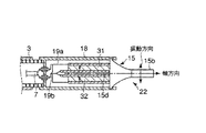
すなわち、図12および図13に示す超音波振動子22は、ホーン15の後端面に軸芯に沿って板状の素子支持部15dが一体に設けられ、この素子支持部15dの上下両面に板状の平板振動子31,32が取付けられて構成される。したがって、平板振動子31、32は素子支持部15dを挟んで対向配置され、平板振動子31、32は図12および図13に示す矢印の方向に分極されることになる。
That is, in the
素子支持部15dに接する−電極31b、32aに−導線19bが接続され、振動子カバー18と向き合う+電極31a、32bに+導線19aが接続されることで、屈曲振動が発生する。このような屈曲振動を得ることができれば、たとえば結石の粉砕に極めて有効である。
Bending vibration is generated by connecting the -
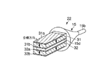
図14に示す超音波振動子22は、対向配置した2つの積層圧電体33、34をホーン15に接着した構成である。積層圧電体33、34は図に矢印に示すように、それぞれ反対方向に分極されている。各積層圧電体33、34における一方の外部電極35、36に+導線19aを接続し、図示しない反対側の外部電極には−導線19bを接続することで屈曲振動が発生する。
The
図15および図16に示す超音波振動子22では、外周方向にねじり振動を発生させることができる。
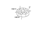
すなわち、図15に示す超音波振動子22は、図17に示すように圧電素子37を径方向に分割して、各分割片fを図中矢印に示す方向に分極したあと、再び貼り合わせてねじり振動子37を構成している。このねじり振動子37をホーン15に取付けることにより、超音波振動子22のねじり振動を可能にしている。
In the
That is, the
図16に示す超音波振動子22は、図中矢印方向に分極した4つの積層圧電体38、39、40、41を互いに対向して配置させることにより、超音波振動子22のねじり振動を可能にしている。なお、積層圧電体38、39および40、41に設けられる外部電極51は+導線19aに接続され、積層圧電体38、39および40、41間に挟まれた−電極52は−導線19bに接続される。
The
つぎに、実施例1に記載の内視鏡1の作用を説明する。
被検体の管腔部内に図1に示す内視鏡1を先端部1Cから挿入し、照明系レンズ50で周囲を照らしながら、観察系レンズ13を介してビデオで観察する。患部を確認したら、内視鏡1の口金部4から超音波処置装置2を構成する超音波振動子22を挿入する。すなわち、ホーン15、振動子カバー18および可撓性シース3の順で、口金部4からチャンネル23内に挿入する。観察を継続しながら操作部6を前後方向に移動操作して、超音波による処置を行うとする処置部位にホーン15の先端処置部15bを当てる。
Next, the operation of the
The
そして、図示しない超音波発生操作手段(例えばフットスイッチやハンドスイッチ)を操作し、超音波発振装置9から信号ケーブル7を通じて駆動信号を圧電素子16に印加する。圧電素子16の作用が超音波振動子22で機械的振動に変換されて超音波振動が発生し、ホーン15の先端処置部15b側に伝達される。したがって、内視鏡1による観察を継続したまま、ホーン15の先端処置部15bに発生する超音波振動によって生体組織の粉砕・乳化・止血等の処置を行える。
Then, an ultrasonic generation operation means (for example, a foot switch or a hand switch) (not shown) is operated, and a drive signal is applied to the
このようにして、ホーン15を覆う振動子カバー18と、この振動子カバー18の後方に一端が連結された中空の可撓性シース3の外径寸法を、内視鏡1を構成するチャンネル23の内径寸法よりも小さく形成してチャンネル23内に挿通し、可撓性シース3の他端に接続された操作部6を前後方向に操作することにより、ホーン15の先端処置部15bがチャンネル23先端から突没自在となり、超音波振動による生体組織の切開・凝固などの処置ができる。可撓管部1Bの湾曲状態に可撓性シース3が追従変形して、可撓管部1Bの動作の円滑性を保持でき、しかも超音波振動子22におけるホーン先端処置部15bの内視鏡先端部1Cに対する突没操作が容易である。
In this way, the outer diameter of the
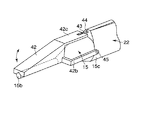
図18〜図20は本発明の実施例2に係る。図18は超音波処置装置における超音波振動子の断面図、図19は超音波振動子の斜視図、図20は超音波処置装置の操作部およびハンドルの一部を切欠した側面図である。なお、先に説明した実施例1と同一部品については同番号を付して新たな説明は省略する。ここでは、実施例1との相違点についてのみ説明する。 18 to 20 relate to the second embodiment of the present invention. 18 is a cross-sectional view of an ultrasonic transducer in the ultrasonic treatment apparatus, FIG. 19 is a perspective view of the ultrasonic transducer, and FIG. 20 is a side view in which a part of an operation unit and a handle of the ultrasonic treatment apparatus are cut out. The same parts as those in the first embodiment described above are denoted by the same reference numerals, and a new description is omitted. Here, only differences from the first embodiment will be described.
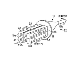
図18および図19に示すように、超音波振動子22はホーン15等の他、鉗子42を備えている。この鉗子42は、ホーン15の先端処置部15bに接する把持面fを有する把持部42aと、この把持部42aの後端に一体に設けられる後端突出部42cおよび、把持部42aの側部に一体に設けられる支持部42bから構成される。
As shown in FIGS. 18 and 19, the
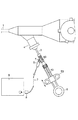
前記後端突起部42cには操作ワイヤ43の一端部が接続されていて、この操作ワイヤ43はホーン15に設けられる操作ワイヤ孔44に挿通する。この操作ワイヤ孔44は、ホーン先端処置部15bの後方に一体に設けられるカバー部15cに開口されている。カバー部15cは、先に図2で説明した振動子カバー18の代用をなす。当然、振動子カバー18を備えて操作ワイヤ43を挿通するようにしてもよい。操作ワイヤ43は、図21に示すように内視鏡1の口金部4を介して操作部6に設けられるハンドル53に接続される。
One end of an
前記鉗子42の支持部42bは、図19に示すように支持ピン45を介してホーン15のカバー部15cに回転自在に支持される。前記ハンドル53は、操作部6に沿ってスライド自在である。ハンドル53を前後方向に移動操作することにより、操作ワイヤ43は鉗子後端突起部42cを前後方向に移動させ、支持ピン45を支点として鉗子42を回動させる。すなわち、ホーン15の先端処置部15bに対し鉗子42の把持部42aが開閉可能となっている。
The
つぎに、実施例2の作用を説明する。
被検体の管腔部内に図1に示す内視鏡1を先端部1Cから挿入し、照明系レンズ50で周囲を照らしながら、観察系レンズ13を介してビデオで観察する。患部を確認したら、内視鏡1の口金部4から超音波処置装置2を構成する超音波振動子22を挿入する。すなわち、ホーン15、振動子カバー18および可撓性シース3の順で、口金部4からチャンネル23内に挿入する。観察を継続しながら操作部6を前後方向に移動操作して、超音波による処置を行うとする処置部位にホーン15の先端処置部15bを当てる。
Next, the operation of the second embodiment will be described.
The
つぎに、ハンドル53を引いて鉗子42を回動し、この把持部42aをホーン15の先端処置部15bに対して開放する。開放状態のまま操作部6を押し込み、処置対象部位となる生体組織を先端処置部15bと把持部42aとの間に介在させる。図示しない超音波発生操作手段(例えばフットスイッチやハンドスイッチ)を操作し、超音波発振装置9から信号ケーブル7を通じて駆動信号を圧電素子16に印加する。
Next, the
圧電素子16の作用が超音波振動子22で機械的振動に変換されて超音波振動が発生し、ホーン15の先端処置部15b側に伝達する。内視鏡1による観察を継続し、ホーン15の先端処置部15bを超音波振動させながらハンドル53を押す。鉗子42が回動してホーン先端処置部15bと鉗子把持部42aとの間に生体組織を挟持し、その状態を保持して粉砕・乳化・止血等の処置が行える。
The action of the
このようにして、可撓管部1Bの湾曲状態に可撓性シース3が追従変形して、可撓管部1Bの動作の円滑性を保持でき、しかも超音波振動子22におけるホーン先端処置部15bの内視鏡先端部1Cに対する突没操作が容易であるとともに、鉗子42と先端処置部15bとで生体組織を挟持しながら超音波処置でき、より確実な処置が可能となる。
In this way, the
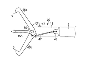
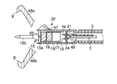
図21、図22は本発明の実施例3に係る。図21は超音波処置装置における超音波振動子先端の正面図、図22は超音波振動子先端の断面図である。なお、先に説明した実施例1と同一部品については同番号を付して新たな説明は省略する。ここでは、実施例1との相違点についてのみ説明する。
21 and 22 relate to
超音波振動子22はホーン15等の他、2つ(一対)の鉗子46a,46bを備えている。それぞれの鉗子46a,46bは先端爪部gを自由端とし、後端部が支持ピン55を介して振動子カバー18に回動自在に支持される。鉗子46a,46bの後端部には操作ワイヤ47の一端部が接続されていて、この操作ワイヤ47は振動子カバー18に設けられるワイヤ用切欠部48を介して、先に[実施例2」で説明したハンドル53に接続されている。前記ハンドル53は、操作部6に沿ってスライド可能であり、ハンドル53を前後方向に移動操作することにより一対の鉗子46a,46bは支持ピン45を支点として互いに反対方向に回動し、ホーン15の先端処置部15bに対して鉗子42a,42bの先端爪部gを開閉可能としている。
The
つぎに、実施例3の作用を説明する。
被検体の管腔部内に図1に示す内視鏡1を先端部1Cから挿入し、照明系レンズ50で周囲を照らしながら、観察系レンズ13を介してビデオで観察する。患部を確認したら、内視鏡1の口金部4から超音波処置装置2を構成する超音波振動子22を挿入する。すなわち、ホーン15、振動子カバー18および可撓性シース3の順で、口金部4からチャンネル23内に挿入する。観察を継続しながら操作部6を前後方向に移動操作して、超音波による処置を行うとする処置部位にホーン15の先端処置部15bを当てる。
Next, the operation of the third embodiment will be described.
The
そして、ハンドル53を押して鉗子46a,46bを回動させ、ホーン15の先端処置部15bに対して鉗子46a,46bを開放する。この状態を保持したまま操作部6を押し込み、処置対象部位を鉗子46a,46b相互の先端爪部g間に介在させる。つぎに、図示しない超音波発生操作手段(例えばフットスイッチやハンドスイッチ)を操作し、超音波発振装置9から信号ケーブル7を通じて駆動信号を圧電素子16に印加する。
Then, the
超音波発振装置9が駆動されホーン15の先端処置部15bを超音波振動させながら、ハンドル53を後ろに引き鉗子46a,46bの先端相互を閉める。そうすることで、処置対象となる生体組織を鉗子46a,46bの爪部gで摘んだまま、切断・止血などの超音波処置を行える。
The
このようにして、可撓管部1Bの湾曲状態に可撓性シース3が追従変形して、可撓管部1Bの動作の円滑性を保持でき、しかも超音波振動子22におけるホーン先端処置部15bの内視鏡先端部1Cに対する突没操作が容易であるとともに、一対の鉗子46a,46bで生体組織を確実に挟持しながら超音波処置することができ、より確実な処置が可能となる。
In this way, the
さらに、本発明は前記実施例の形態に限定されるものではなく、本発明の要旨を逸脱しない範囲で種々変形実施できることは勿論である。
つぎに、本発明の他の特徴的な技術事項を下記の通り付記する。
記
(付記項1) 超音波振動を発生させ、その超音波振動を先端処置部に伝達させることで被検体の処置をする超音波振動子と、超音波振動子の処置部以外を覆う振動子カバーと、前記振動子カバーの後端に接続された長尺の可撓性シースと、前記可撓性シースの一端に接続された操作部と、前記可撓性シースの内部に埋設され、前記超音波振動子に電気信号を伝達する配線ケーブルと、電気信号を発生して前記超音波振動子を駆動させる電源とを備えることを特徴とする超音波処置装置。
Furthermore, the present invention is not limited to the embodiment described above, and various modifications can be made without departing from the scope of the present invention.
Next, other characteristic technical matters of the present invention are appended as follows.
(Additional Item 1) An ultrasonic transducer that generates ultrasonic vibration and transmits the ultrasonic vibration to the distal treatment section to treat the subject, and a vibrator that covers the ultrasonic vibrator other than the treatment section A cover, a long flexible sheath connected to the rear end of the vibrator cover, an operation unit connected to one end of the flexible sheath, and embedded in the flexible sheath, An ultrasonic treatment apparatus comprising: a wiring cable that transmits an electrical signal to an ultrasonic transducer; and a power source that generates the electrical signal and drives the ultrasonic transducer.
(付記項2) 付記項1記載の超音波処置装置において、前記振動子カバー及び可撓性シースの外径は、内視鏡のチャンネル内径より小さく、前記振動子カバーに覆われた超音波振動子は、一端がシースに接続された操作部を前後することにより、内視鏡のチャンネル内を出し入れ可能であることを特徴とする超音波処置装置。
(Additional Item 2) In the ultrasonic treatment apparatus according to
(付記項3) 付記項1記載の超音波処置装置において、前記振動子カバーは、前記超音波振動子の振動の節位置に固定されたことを特徴とする超音波処置装置。
(Additional Item 3) The ultrasonic treatment apparatus according to
(付記項4) 付記項1記載の超音波処置装置において、前記超音波振動子の処置部先端は、前記振動子カバーが固定される節位置から、1/4波長の距離にあることを特徴とする超音波処置装置。
(Additional Item 4) In the ultrasonic treatment device according to
(付記項5) 付記項1記載の超音波処置装置において、前記超音波振動子は、先端処置部を含むホーンと、電気信号を機械的振動に変換する複数の圧電素子と、圧電素子に電気信号を供給する複数の電極と、裏打板とから構成され、前記振動子カバーを振動の節位置にあたるホーンと圧電素子との間に挟持し、ホーン、振動子カバー、圧電素子、電極、及び裏打板を埋め込みボルトで固定したことを特徴とする超音波処置装置。
(Additional Item 5) In the ultrasonic treatment apparatus according to
(付記項6) 付記項1記載の超音波処置装置において、前記超音波振動子のホーンと振動子カバーが一体に形成されていることを特徴とする超音波処置装置。
(Additional Item 6) The ultrasonic treatment device according to
(付記項7) 付記項1記載の超音波処置装置において、前記超音波振動子は、先端処置部を含むホーンと、圧電層と内部電極を交互に積層した積層圧電体とから構成されることを特徴とする超音波処置装置。
(Additional Item 7) In the ultrasonic treatment apparatus according to
(付記項8) 付記項1記載の超音波処置装置において、前記超音波振動子は、振動子の中心軸に対して垂直方向に振動する屈曲(横)振動することを特徴とする超音波処置装置。
(Additional Item 8) The ultrasonic treatment apparatus according to
(付記項9) 付記項1記載の超音波処置装置において、前記超音波振動子は、振動子の中心軸に対して円周方向に振動するねじり振動することを特徴とする超音波処置装置。
(Additional Item 9) The ultrasonic treatment device according to
(付記項10) 超音波振動を発生させ、その超音波振動を先端処置部に伝達させることで被検体の処置をする超音波振動子と、超音波振動子の処置部以外を覆う振動子カバーと、振動子カバーに回転自由に固定され、一端が操作ワイヤに接続されている鉗子と、操作ワイヤの一端に接続されたハンドルと、前記振動子カバーの後端に接続された長尺の可撓性シースと、前記可撓性シースの一端に接続された操作部と、前記可撓性シースの内部に埋設され、前記超音波振動子に電気信号を伝達する配線ケーブルと、電気信号を発生して前記超音波振動子を駆動させる電源とを備えることを特徴とする超音波処置装置。 (Additional Item 10) An ultrasonic vibrator that treats a subject by generating ultrasonic vibration and transmitting the ultrasonic vibration to the distal treatment section, and a vibrator cover that covers other than the treatment section of the ultrasonic vibrator A forceps that is rotatably fixed to the transducer cover and that has one end connected to the operation wire, a handle that is connected to one end of the operation wire, and a long length that is connected to the rear end of the transducer cover. A flexible sheath, an operation unit connected to one end of the flexible sheath, a wiring cable embedded in the flexible sheath and transmitting an electrical signal to the ultrasonic transducer, and an electrical signal are generated And a power source for driving the ultrasonic transducer.
(付記項11) 付記項10記載の超音波処置装置において、前記鉗子、振動子カバー及び可撓性シースの外形は、内視鏡のチャンネル内径より小さく、前記振動子カバーに覆われた超音波振動子と、振動子カバーに回転自由に固定された鉗子は、一端がシースに接続された操作部を前後することにより、内視鏡のチャンネル内を出し入れ可能であることを特徴とする超音波処置装置。
(Additional Item 11) In the ultrasonic treatment device according to
(付記項12) 付記項10記載の超音波処置装置において、操作ワイヤの一端に接続されているハンドルを前後することで、鉗子が開閉自在になることを特徴とする超音波処置装置。
(Additional Item 12) The ultrasonic treatment device according to
(付記項13) 付記項10記載の超音波処置装置において、複数の鉗子を有することを特徴とする超音波処置装置。
(Additional Item 13) The ultrasonic treatment device according to
22…超音波振動子、18…振動子カバー(カバー部材)、3…可撓性シース、7…信号ケーブル、9…超音波発振装置(超音波駆動手段)、6…操作部、8…コネクタ(コネクタ手段)、5…ケーブル取出し口、42,46…鉗子(鉗子部材)、43,47…操作ワイヤ、53…ハンドル(ハンドル手段)。
DESCRIPTION OF
Claims (9)
前記超音波振動子を覆うカバー部材と、
前記カバー部材に一端が連結される中空の可撓性シースと、
前記カバー部材に覆われた前記超音波振動子に一端が接続され、前記可撓性シースの内部に挿通される信号ケーブルと、
前記信号ケーブルの他端に接続され、前記超音波振動子を駆動する駆動信号を発生するための超音波駆動手段と、
前記可撓性シースの他端部に設けられ、操作者の操作に応じて前記カバー部材とともに前記超音波振動子を変位可能な操作部と
を具備することを特徴とする超音波処置装置。 An ultrasonic transducer capable of generating ultrasonic vibration for treating living tissue;
A cover member covering the ultrasonic transducer;
A hollow flexible sheath having one end connected to the cover member;
One end of the ultrasonic transducer covered with the cover member is connected, and a signal cable inserted into the flexible sheath;
An ultrasonic drive means connected to the other end of the signal cable for generating a drive signal for driving the ultrasonic transducer;
An ultrasonic treatment apparatus, comprising: an operation unit provided at the other end of the flexible sheath and capable of displacing the ultrasonic transducer together with the cover member according to an operation of an operator.
前記超音波振動子を覆うカバー部材と、
前記カバー部材の後方に一端が連結される中空の可撓性シースと、
前記カバー部材に覆われる前記超音波振動子に一端が接続され、前記可撓性シースの内部に挿通される信号ケーブルと、
前記信号ケーブルの他端に設けられ、前記超音波振動子を駆動する駆動信号を発生するための超音波駆動手段に接続可能なコネクタ手段と、
前記可撓性シースの他端部に設けられ、操作者の操作に応じて前記カバー部材とともに前記超音波振動子を変位可能な操作部と
を具備することを特徴とする超音波処置装置。 An ultrasonic transducer capable of generating ultrasonic vibration for treating living tissue;
A cover member covering the ultrasonic transducer;
A hollow flexible sheath having one end connected to the rear of the cover member;
One end of the ultrasonic transducer covered by the cover member is connected, and a signal cable inserted into the flexible sheath;
Connector means provided at the other end of the signal cable and connectable to an ultrasonic drive means for generating a drive signal for driving the ultrasonic transducer;
An ultrasonic treatment apparatus, comprising: an operation unit provided at the other end of the flexible sheath and capable of displacing the ultrasonic transducer together with the cover member according to an operation of an operator.
前記カバー部材の後方に一端が連結される中空の可撓性シースと、
前記カバー部材に覆われた前記超音波振動子に一端が接続され、前記可撓性シースの内部に挿通される信号ケーブルと、
前記可撓性シースに挿通される前記信号ケーブルの他端を取出し可能なケーブル取出し口を有し、前記可撓性シースの他端に設けられ、操作者の操作に応じて前記カバー部材とともに前記超音波振動子を変位可能な操作部と、
前記操作部の前記ケーブル取出し口から取出された信号ケーブルの他端に接続され、前記超音波振動子を駆動する駆動信号を発生するための超音波駆動手段と
を具備することを特徴とする超音波処置装置。 A cover member covering an ultrasonic transducer capable of generating ultrasonic vibration for treating a living tissue;
A hollow flexible sheath having one end connected to the rear of the cover member;
One end of the ultrasonic transducer covered with the cover member is connected, and a signal cable inserted into the flexible sheath;
A cable outlet through which the other end of the signal cable inserted into the flexible sheath can be taken out; provided at the other end of the flexible sheath; and together with the cover member according to the operation of the operator An operation unit capable of displacing the ultrasonic transducer;
Ultrasonic drive means for generating a drive signal connected to the other end of the signal cable taken out from the cable outlet of the operation section and driving the ultrasonic transducer Sonic treatment device.
前記カバー部材の後方に一端が連結され、内部に前記超音波振動子から延出された信号ケーブルを挿通可能な中空の可撓性シースと、
前記可撓性シースの他端に設けられ、操作者の操作に応じて前記カバー部材とともに前記超音波振動子を変位可能な操作部と、
前記操作部に設けられ、前記可撓性シースに挿通される前記信号ケーブルの端部を取出し可能なケーブル取出し口と、
前記ケーブル取出し口から取出された前記信号ケーブルの端部に設けられ、前記超音波振動子を駆動する駆動信号を発生するための超音波駆動手段に接続可能なコネクタ手段とを具備することを特徴とする超音波処置装置。 A cover member for covering an ultrasonic transducer capable of generating ultrasonic vibration for treating a biological tissue;
A hollow flexible sheath, one end of which is connected to the rear of the cover member and into which a signal cable extending from the ultrasonic transducer can be inserted;
An operating portion that is provided at the other end of the flexible sheath and is capable of displacing the ultrasonic transducer together with the cover member in accordance with an operation of an operator;
A cable outlet provided in the operation portion and capable of taking out an end portion of the signal cable inserted through the flexible sheath;
Connector means provided at an end portion of the signal cable taken out from the cable outlet, and connectable to an ultrasonic driving means for generating a driving signal for driving the ultrasonic transducer. An ultrasonic treatment device.
前記超音波振動子を覆うカバー部材と、
前記カバー部材の後方に一端が連結され、内部に前記超音波振動子から延出される信号ケーブルを挿通する中空の可撓性シースと、
前記可撓性シース内部に挿通される前記信号ケーブルを前記駆動装置に接続するためのケーブル取出し口を有し、前記可撓性シースの他端に設けられ操作者の操作に応じて前記カバー部材とともに前記超音波振動子を変位可能な操作部と
を具備することを特徴とする超音波処置装置。 In an ultrasonic treatment apparatus having an ultrasonic transducer capable of generating ultrasonic vibration for treating a biological tissue and connectable to a drive device for driving the ultrasonic transducer,
A cover member covering the ultrasonic transducer;
A hollow flexible sheath having one end connected to the rear of the cover member and inserting a signal cable extending from the ultrasonic transducer inside;
The cover member has a cable outlet for connecting the signal cable inserted into the flexible sheath to the driving device, and is provided at the other end of the flexible sheath according to the operation of the operator. And an operation unit capable of displacing the ultrasonic transducer.
前記超音波振動子を覆うカバー部材と、
前記カバー部材の後方に一端が連結される中空の可撓性シースと、
前記カバー部材に覆われる前記超音波振動子に一端が接続され、前記可撓性シースの内部に挿通される信号ケーブルと、
前記信号ケーブルの他端に接続され、前記超音波振動子を駆動する駆動信号を発生するための超音波駆動手段と、
前記可撓性シースの他端部に設けられ、操作者の操作に応じて前記カバー部材とともに前記超音波振動子を変位可能な操作部と、
前記カバー部材に回動自在に設けられた鉗子部材と、
前記鉗子部材に一端が接続され、前記可撓性シースの内部に挿通される操作ワイヤと、
前記操作ワイヤの他端に接続され、前記操作部に対して移動可能なハンドル手段と
を具備することを特徴とする超音波処置装置。 An ultrasonic transducer capable of generating ultrasonic vibration for treating living tissue;
A cover member covering the ultrasonic transducer;
A hollow flexible sheath having one end connected to the rear of the cover member;
One end of the ultrasonic transducer covered by the cover member is connected, and a signal cable inserted into the flexible sheath;
An ultrasonic drive means connected to the other end of the signal cable for generating a drive signal for driving the ultrasonic transducer;
An operating portion that is provided at the other end of the flexible sheath and is capable of displacing the ultrasonic transducer together with the cover member in accordance with an operation of an operator;
A forceps member provided rotatably on the cover member;
One end of the forceps member is connected, and an operation wire inserted into the flexible sheath;
An ultrasonic treatment apparatus comprising: handle means connected to the other end of the operation wire and movable with respect to the operation unit.
前記超音波振動子を覆うためのカバー部材と、
前記カバー部材の後方に一端が連結される中空の可撓性シースと、
前記カバー部材に覆われる前記超音波振動子に一端が接続され、前記可撓性シースの内部に挿通される信号ケーブルと、
前記信号ケーブルの他端に設けられ、前記超音波振動子を駆動する駆動信号を発生するための超音波駆動手段に接続可能なコネクタ手段と、
前記可撓性シースの他端部に設けられ、操作者の操作に応じて前記カバー部材とともに前記超音波振動子を変位可能な操作部と、
前記カバー部材に回動自在に設けられた鉗子部材と、
前記鉗子部材に一端が接続され、可撓性シースの内部に挿通される操作ワイヤと、
前記操作ワイヤの他端に接続され、前記操作部に対して移動可能なハンドル手段と
を具備することを特徴とする超音波処置装置。 An ultrasonic transducer capable of generating ultrasonic vibration for treating living tissue;
A cover member for covering the ultrasonic transducer;
A hollow flexible sheath having one end connected to the rear of the cover member;
One end of the ultrasonic transducer covered by the cover member is connected, and a signal cable inserted into the flexible sheath;
Connector means provided at the other end of the signal cable and connectable to an ultrasonic drive means for generating a drive signal for driving the ultrasonic transducer;
An operating portion that is provided at the other end of the flexible sheath and is capable of displacing the ultrasonic transducer together with the cover member in accordance with an operation of an operator;
A forceps member provided rotatably on the cover member;
One end is connected to the forceps member, an operation wire inserted into the flexible sheath,
An ultrasonic treatment apparatus comprising: handle means connected to the other end of the operation wire and movable with respect to the operation unit.
Priority Applications (4)
| Application Number | Priority Date | Filing Date | Title |
|---|---|---|---|
| JP2003304709A JP3999715B2 (en) | 2003-08-28 | 2003-08-28 | Ultrasonic treatment device |
| US10/925,374 US7449004B2 (en) | 2003-08-28 | 2004-08-24 | Ultrasonic treatment device and ultrasonic treatment system |
| AT04020181T ATE511802T1 (en) | 2003-08-28 | 2004-08-25 | ULTRASONIC DEVICE AND ULTRASONIC TREATMENT SYSTEM |
| EP04020181A EP1510178B1 (en) | 2003-08-28 | 2004-08-25 | Ultrasonic treatment device and ultrasonic treatment system |
Applications Claiming Priority (1)
| Application Number | Priority Date | Filing Date | Title |
|---|---|---|---|
| JP2003304709A JP3999715B2 (en) | 2003-08-28 | 2003-08-28 | Ultrasonic treatment device |
Publications (2)
| Publication Number | Publication Date |
|---|---|
| JP2005073746A true JP2005073746A (en) | 2005-03-24 |
| JP3999715B2 JP3999715B2 (en) | 2007-10-31 |
Family
ID=34101222
Family Applications (1)
| Application Number | Title | Priority Date | Filing Date |
|---|---|---|---|
| JP2003304709A Expired - Fee Related JP3999715B2 (en) | 2003-08-28 | 2003-08-28 | Ultrasonic treatment device |
Country Status (4)
| Country | Link |
|---|---|
| US (1) | US7449004B2 (en) |
| EP (1) | EP1510178B1 (en) |
| JP (1) | JP3999715B2 (en) |
| AT (1) | ATE511802T1 (en) |
Cited By (7)
| Publication number | Priority date | Publication date | Assignee | Title |
|---|---|---|---|---|
| WO2013061738A1 (en) * | 2011-10-24 | 2013-05-02 | Olympus Corporation | Ultrasonic vibration apparatus |
| WO2015001822A1 (en) * | 2013-07-03 | 2015-01-08 | オリンパス株式会社 | Ultrasonic vibration device, ultrasonic vibration device manufacturing method, and ultrasonic medical apparatus |
| JP2015524683A (en) * | 2012-06-29 | 2015-08-27 | エシコン・エンド−サージェリィ・インコーポレイテッドEthicon Endo−Surgery,Inc. | Ultrasonic surgical instrument having a distally disposed jaw assembly |
| WO2016051486A1 (en) * | 2014-09-30 | 2016-04-07 | オリンパス株式会社 | Ultrasonic vibrator and ultrasonic medical apparatus |
| JP2018167075A (en) * | 2012-09-19 | 2018-11-01 | エシコン・エンド−サージェリィ・インコーポレイテッドEthicon Endo−Surgery,Inc. | Micromachined ultrasonic scalpel with embedded piezoelectric actuator |
| JP2019534058A (en) * | 2016-08-25 | 2019-11-28 | エシコン エルエルシーEthicon LLC | Acoustic coupling, connection and configuration of ultrasonic transducers to waveguides |
| KR20200037777A (en) * | 2017-06-30 | 2020-04-09 | 인라이튼뷰 엘엘씨 | Endoscopy system and how to use it |
Families Citing this family (187)
| Publication number | Priority date | Publication date | Assignee | Title |
|---|---|---|---|---|
| US11229472B2 (en) | 2001-06-12 | 2022-01-25 | Cilag Gmbh International | Modular battery powered handheld surgical instrument with multiple magnetic position sensors |
| US8182501B2 (en) | 2004-02-27 | 2012-05-22 | Ethicon Endo-Surgery, Inc. | Ultrasonic surgical shears and method for sealing a blood vessel using same |
| EP3162309B1 (en) | 2004-10-08 | 2022-10-26 | Ethicon LLC | Ultrasonic surgical instrument |
| US20060116610A1 (en) * | 2004-11-30 | 2006-06-01 | Omnisonics Medical Technologies, Inc. | Apparatus and method for an ultrasonic medical device with variable frequency drive |
| US20070191713A1 (en) | 2005-10-14 | 2007-08-16 | Eichmann Stephen E | Ultrasonic device for cutting and coagulating |
| US7621930B2 (en) | 2006-01-20 | 2009-11-24 | Ethicon Endo-Surgery, Inc. | Ultrasound medical instrument having a medical ultrasonic blade |
| US20080200940A1 (en) * | 2007-01-16 | 2008-08-21 | Eichmann Stephen E | Ultrasonic device for cutting and coagulating |
| US8226675B2 (en) | 2007-03-22 | 2012-07-24 | Ethicon Endo-Surgery, Inc. | Surgical instruments |
| US8057498B2 (en) | 2007-11-30 | 2011-11-15 | Ethicon Endo-Surgery, Inc. | Ultrasonic surgical instrument blades |
| US8911460B2 (en) | 2007-03-22 | 2014-12-16 | Ethicon Endo-Surgery, Inc. | Ultrasonic surgical instruments |
| US8142461B2 (en) | 2007-03-22 | 2012-03-27 | Ethicon Endo-Surgery, Inc. | Surgical instruments |
| JP2008264253A (en) * | 2007-04-20 | 2008-11-06 | Olympus Medical Systems Corp | Medical treatment tool and endoscope treatment system |
| US20090044880A1 (en) * | 2007-06-16 | 2009-02-19 | Jody Jones | Log cutting |
| US8187168B2 (en) * | 2007-07-09 | 2012-05-29 | David George Wuchinich | Retractable ultrasonic endoscopic aspirator |
| US8882791B2 (en) | 2007-07-27 | 2014-11-11 | Ethicon Endo-Surgery, Inc. | Ultrasonic surgical instruments |
| US8523889B2 (en) | 2007-07-27 | 2013-09-03 | Ethicon Endo-Surgery, Inc. | Ultrasonic end effectors with increased active length |
| US8808319B2 (en) | 2007-07-27 | 2014-08-19 | Ethicon Endo-Surgery, Inc. | Surgical instruments |
| US8512365B2 (en) | 2007-07-31 | 2013-08-20 | Ethicon Endo-Surgery, Inc. | Surgical instruments |
| US9044261B2 (en) | 2007-07-31 | 2015-06-02 | Ethicon Endo-Surgery, Inc. | Temperature controlled ultrasonic surgical instruments |
| US8430898B2 (en) | 2007-07-31 | 2013-04-30 | Ethicon Endo-Surgery, Inc. | Ultrasonic surgical instruments |
| AU2008308606B2 (en) | 2007-10-05 | 2014-12-18 | Ethicon Endo-Surgery, Inc. | Ergonomic surgical instruments |
| US10010339B2 (en) | 2007-11-30 | 2018-07-03 | Ethicon Llc | Ultrasonic surgical blades |
| US9089360B2 (en) | 2008-08-06 | 2015-07-28 | Ethicon Endo-Surgery, Inc. | Devices and techniques for cutting and coagulating tissue |
| US8974477B2 (en) * | 2008-08-29 | 2015-03-10 | Olympus Medical Systems Corp. | Ultrasonic operating apparatus |
| US9700339B2 (en) | 2009-05-20 | 2017-07-11 | Ethicon Endo-Surgery, Inc. | Coupling arrangements and methods for attaching tools to ultrasonic surgical instruments |
| US8334635B2 (en) | 2009-06-24 | 2012-12-18 | Ethicon Endo-Surgery, Inc. | Transducer arrangements for ultrasonic surgical instruments |
| US8663220B2 (en) | 2009-07-15 | 2014-03-04 | Ethicon Endo-Surgery, Inc. | Ultrasonic surgical instruments |
| US9039695B2 (en) | 2009-10-09 | 2015-05-26 | Ethicon Endo-Surgery, Inc. | Surgical generator for ultrasonic and electrosurgical devices |
| US10441345B2 (en) | 2009-10-09 | 2019-10-15 | Ethicon Llc | Surgical generator for ultrasonic and electrosurgical devices |
| US9168054B2 (en) | 2009-10-09 | 2015-10-27 | Ethicon Endo-Surgery, Inc. | Surgical generator for ultrasonic and electrosurgical devices |
| US11090104B2 (en) | 2009-10-09 | 2021-08-17 | Cilag Gmbh International | Surgical generator for ultrasonic and electrosurgical devices |
| USRE47996E1 (en) | 2009-10-09 | 2020-05-19 | Ethicon Llc | Surgical generator for ultrasonic and electrosurgical devices |
| US10172669B2 (en) | 2009-10-09 | 2019-01-08 | Ethicon Llc | Surgical instrument comprising an energy trigger lockout |
| US8376970B2 (en) * | 2009-10-29 | 2013-02-19 | Eilaz Babaev | Ultrasound apparatus and methods for mitigation of neurological damage |
| US8961547B2 (en) | 2010-02-11 | 2015-02-24 | Ethicon Endo-Surgery, Inc. | Ultrasonic surgical instruments with moving cutting implement |
| US8579928B2 (en) | 2010-02-11 | 2013-11-12 | Ethicon Endo-Surgery, Inc. | Outer sheath and blade arrangements for ultrasonic surgical instruments |
| US8469981B2 (en) | 2010-02-11 | 2013-06-25 | Ethicon Endo-Surgery, Inc. | Rotatable cutting implement arrangements for ultrasonic surgical instruments |
| US8951272B2 (en) | 2010-02-11 | 2015-02-10 | Ethicon Endo-Surgery, Inc. | Seal arrangements for ultrasonically powered surgical instruments |
| US8486096B2 (en) | 2010-02-11 | 2013-07-16 | Ethicon Endo-Surgery, Inc. | Dual purpose surgical instrument for cutting and coagulating tissue |
| US8834518B2 (en) | 2010-04-12 | 2014-09-16 | Ethicon Endo-Surgery, Inc. | Electrosurgical cutting and sealing instruments with cam-actuated jaws |
| GB2480498A (en) | 2010-05-21 | 2011-11-23 | Ethicon Endo Surgery Inc | Medical device comprising RF circuitry |
| US8795327B2 (en) | 2010-07-22 | 2014-08-05 | Ethicon Endo-Surgery, Inc. | Electrosurgical instrument with separate closure and cutting members |
| US9192431B2 (en) | 2010-07-23 | 2015-11-24 | Ethicon Endo-Surgery, Inc. | Electrosurgical cutting and sealing instrument |
| US8979890B2 (en) | 2010-10-01 | 2015-03-17 | Ethicon Endo-Surgery, Inc. | Surgical instrument with jaw member |
| US9259265B2 (en) | 2011-07-22 | 2016-02-16 | Ethicon Endo-Surgery, Llc | Surgical instruments for tensioning tissue |
| JP5851147B2 (en) * | 2011-08-05 | 2016-02-03 | オリンパス株式会社 | Ultrasonic vibration device |
| US9044243B2 (en) | 2011-08-30 | 2015-06-02 | Ethcon Endo-Surgery, Inc. | Surgical cutting and fastening device with descendible second trigger arrangement |
| US10085762B2 (en) | 2011-10-21 | 2018-10-02 | Ethicon Llc | Ultrasonic device for cutting and coagulating |
| US9421060B2 (en) | 2011-10-24 | 2016-08-23 | Ethicon Endo-Surgery, Llc | Litz wire battery powered device |
| JP6165780B2 (en) | 2012-02-10 | 2017-07-19 | エシコン・エンド−サージェリィ・インコーポレイテッドEthicon Endo−Surgery,Inc. | Robot-controlled surgical instrument |
| US9226766B2 (en) | 2012-04-09 | 2016-01-05 | Ethicon Endo-Surgery, Inc. | Serial communication protocol for medical device |
| US9724118B2 (en) | 2012-04-09 | 2017-08-08 | Ethicon Endo-Surgery, Llc | Techniques for cutting and coagulating tissue for ultrasonic surgical instruments |
| US9439668B2 (en) | 2012-04-09 | 2016-09-13 | Ethicon Endo-Surgery, Llc | Switch arrangements for ultrasonic surgical instruments |
| US9237921B2 (en) | 2012-04-09 | 2016-01-19 | Ethicon Endo-Surgery, Inc. | Devices and techniques for cutting and coagulating tissue |
| US9241731B2 (en) | 2012-04-09 | 2016-01-26 | Ethicon Endo-Surgery, Inc. | Rotatable electrical connection for ultrasonic surgical instruments |
| US20140005705A1 (en) | 2012-06-29 | 2014-01-02 | Ethicon Endo-Surgery, Inc. | Surgical instruments with articulating shafts |
| US9198714B2 (en) | 2012-06-29 | 2015-12-01 | Ethicon Endo-Surgery, Inc. | Haptic feedback devices for surgical robot |
| US9820768B2 (en) | 2012-06-29 | 2017-11-21 | Ethicon Llc | Ultrasonic surgical instruments with control mechanisms |
| US9393037B2 (en) | 2012-06-29 | 2016-07-19 | Ethicon Endo-Surgery, Llc | Surgical instruments with articulating shafts |
| US9226767B2 (en) | 2012-06-29 | 2016-01-05 | Ethicon Endo-Surgery, Inc. | Closed feedback control for electrosurgical device |
| US9326788B2 (en) | 2012-06-29 | 2016-05-03 | Ethicon Endo-Surgery, Llc | Lockout mechanism for use with robotic electrosurgical device |
| US9283045B2 (en) | 2012-06-29 | 2016-03-15 | Ethicon Endo-Surgery, Llc | Surgical instruments with fluid management system |
| US9408622B2 (en) | 2012-06-29 | 2016-08-09 | Ethicon Endo-Surgery, Llc | Surgical instruments with articulating shafts |
| US20140005702A1 (en) | 2012-06-29 | 2014-01-02 | Ethicon Endo-Surgery, Inc. | Ultrasonic surgical instruments with distally positioned transducers |
| WO2014052181A1 (en) | 2012-09-28 | 2014-04-03 | Ethicon Endo-Surgery, Inc. | Multi-function bi-polar forceps |
| US10201365B2 (en) | 2012-10-22 | 2019-02-12 | Ethicon Llc | Surgeon feedback sensing and display methods |
| US9095367B2 (en) | 2012-10-22 | 2015-08-04 | Ethicon Endo-Surgery, Inc. | Flexible harmonic waveguides/blades for surgical instruments |
| DE102012219354A1 (en) * | 2012-10-23 | 2014-04-24 | Olympus Winter & Ibe Gmbh | Actuator for a surgical instrument |
| US20140135804A1 (en) | 2012-11-15 | 2014-05-15 | Ethicon Endo-Surgery, Inc. | Ultrasonic and electrosurgical devices |
| US10265119B2 (en) * | 2013-02-15 | 2019-04-23 | Covidien Lp | Electrosurgical forceps |
| US10226273B2 (en) | 2013-03-14 | 2019-03-12 | Ethicon Llc | Mechanical fasteners for use with surgical energy devices |
| US9241728B2 (en) | 2013-03-15 | 2016-01-26 | Ethicon Endo-Surgery, Inc. | Surgical instrument with multiple clamping mechanisms |
| DE102013011964A1 (en) * | 2013-07-15 | 2015-01-15 | SRH Wald-Klinikum Gera gGmbH | Arrangement and method for in vitro and in vivo treatment of lung tumors |
| GB201315755D0 (en) * | 2013-09-04 | 2013-10-16 | Univ Glasgow | Device and method for causing aggregation of blood cells and method of treating bleeding from an injury. |
| US9814514B2 (en) | 2013-09-13 | 2017-11-14 | Ethicon Llc | Electrosurgical (RF) medical instruments for cutting and coagulating tissue |
| US9265926B2 (en) | 2013-11-08 | 2016-02-23 | Ethicon Endo-Surgery, Llc | Electrosurgical devices |
| GB2521229A (en) | 2013-12-16 | 2015-06-17 | Ethicon Endo Surgery Inc | Medical device |
| GB2521228A (en) | 2013-12-16 | 2015-06-17 | Ethicon Endo Surgery Inc | Medical device |
| US9795436B2 (en) | 2014-01-07 | 2017-10-24 | Ethicon Llc | Harvesting energy from a surgical generator |
| US9554854B2 (en) | 2014-03-18 | 2017-01-31 | Ethicon Endo-Surgery, Llc | Detecting short circuits in electrosurgical medical devices |
| US10463421B2 (en) | 2014-03-27 | 2019-11-05 | Ethicon Llc | Two stage trigger, clamp and cut bipolar vessel sealer |
| US10092310B2 (en) | 2014-03-27 | 2018-10-09 | Ethicon Llc | Electrosurgical devices |
| US10524852B1 (en) | 2014-03-28 | 2020-01-07 | Ethicon Llc | Distal sealing end effector with spacers |
| US9737355B2 (en) | 2014-03-31 | 2017-08-22 | Ethicon Llc | Controlling impedance rise in electrosurgical medical devices |
| US9913680B2 (en) | 2014-04-15 | 2018-03-13 | Ethicon Llc | Software algorithms for electrosurgical instruments |
| US9757186B2 (en) | 2014-04-17 | 2017-09-12 | Ethicon Llc | Device status feedback for bipolar tissue spacer |
| US9700333B2 (en) | 2014-06-30 | 2017-07-11 | Ethicon Llc | Surgical instrument with variable tissue compression |
| US10285724B2 (en) | 2014-07-31 | 2019-05-14 | Ethicon Llc | Actuation mechanisms and load adjustment assemblies for surgical instruments |
| US9877776B2 (en) | 2014-08-25 | 2018-01-30 | Ethicon Llc | Simultaneous I-beam and spring driven cam jaw closure mechanism |
| US10194976B2 (en) | 2014-08-25 | 2019-02-05 | Ethicon Llc | Lockout disabling mechanism |
| US10194972B2 (en) | 2014-08-26 | 2019-02-05 | Ethicon Llc | Managing tissue treatment |
| US10639092B2 (en) | 2014-12-08 | 2020-05-05 | Ethicon Llc | Electrode configurations for surgical instruments |
| US10092348B2 (en) | 2014-12-22 | 2018-10-09 | Ethicon Llc | RF tissue sealer, shear grip, trigger lock mechanism and energy activation |
| US9848937B2 (en) | 2014-12-22 | 2017-12-26 | Ethicon Llc | End effector with detectable configurations |
| US10111699B2 (en) | 2014-12-22 | 2018-10-30 | Ethicon Llc | RF tissue sealer, shear grip, trigger lock mechanism and energy activation |
| US10159524B2 (en) | 2014-12-22 | 2018-12-25 | Ethicon Llc | High power battery powered RF amplifier topology |
| US10245095B2 (en) | 2015-02-06 | 2019-04-02 | Ethicon Llc | Electrosurgical instrument with rotation and articulation mechanisms |
| US10342602B2 (en) | 2015-03-17 | 2019-07-09 | Ethicon Llc | Managing tissue treatment |
| US10321950B2 (en) | 2015-03-17 | 2019-06-18 | Ethicon Llc | Managing tissue treatment |
| US10595929B2 (en) | 2015-03-24 | 2020-03-24 | Ethicon Llc | Surgical instruments with firing system overload protection mechanisms |
| US10314638B2 (en) | 2015-04-07 | 2019-06-11 | Ethicon Llc | Articulating radio frequency (RF) tissue seal with articulating state sensing |
| US10117702B2 (en) | 2015-04-10 | 2018-11-06 | Ethicon Llc | Surgical generator systems and related methods |
| US10130410B2 (en) | 2015-04-17 | 2018-11-20 | Ethicon Llc | Electrosurgical instrument including a cutting member decouplable from a cutting member trigger |
| US9872725B2 (en) | 2015-04-29 | 2018-01-23 | Ethicon Llc | RF tissue sealer with mode selection |
| US10034684B2 (en) | 2015-06-15 | 2018-07-31 | Ethicon Llc | Apparatus and method for dissecting and coagulating tissue |
| US11020140B2 (en) | 2015-06-17 | 2021-06-01 | Cilag Gmbh International | Ultrasonic surgical blade for use with ultrasonic surgical instruments |
| US10357303B2 (en) | 2015-06-30 | 2019-07-23 | Ethicon Llc | Translatable outer tube for sealing using shielded lap chole dissector |
| US10765470B2 (en) | 2015-06-30 | 2020-09-08 | Ethicon Llc | Surgical system with user adaptable techniques employing simultaneous energy modalities based on tissue parameters |
| US10034704B2 (en) | 2015-06-30 | 2018-07-31 | Ethicon Llc | Surgical instrument with user adaptable algorithms |
| US11051873B2 (en) | 2015-06-30 | 2021-07-06 | Cilag Gmbh International | Surgical system with user adaptable techniques employing multiple energy modalities based on tissue parameters |
| US10898256B2 (en) | 2015-06-30 | 2021-01-26 | Ethicon Llc | Surgical system with user adaptable techniques based on tissue impedance |
| US11129669B2 (en) | 2015-06-30 | 2021-09-28 | Cilag Gmbh International | Surgical system with user adaptable techniques based on tissue type |
| US10154852B2 (en) | 2015-07-01 | 2018-12-18 | Ethicon Llc | Ultrasonic surgical blade with improved cutting and coagulation features |
| US9913570B2 (en) | 2015-08-07 | 2018-03-13 | Enlightenvue Llc | Endoscope with variable profile tip |
| US10687884B2 (en) | 2015-09-30 | 2020-06-23 | Ethicon Llc | Circuits for supplying isolated direct current (DC) voltage to surgical instruments |
| US10595930B2 (en) | 2015-10-16 | 2020-03-24 | Ethicon Llc | Electrode wiping surgical device |
| US10959771B2 (en) | 2015-10-16 | 2021-03-30 | Ethicon Llc | Suction and irrigation sealing grasper |
| EP3313301A1 (en) * | 2015-10-23 | 2018-05-02 | Boston Scientific Scimed, Inc. | Ultrasonic treatment devices and systems |
| US10179022B2 (en) | 2015-12-30 | 2019-01-15 | Ethicon Llc | Jaw position impedance limiter for electrosurgical instrument |
| US10959806B2 (en) | 2015-12-30 | 2021-03-30 | Ethicon Llc | Energized medical device with reusable handle |
| US10575892B2 (en) | 2015-12-31 | 2020-03-03 | Ethicon Llc | Adapter for electrical surgical instruments |
| US11229471B2 (en) | 2016-01-15 | 2022-01-25 | Cilag Gmbh International | Modular battery powered handheld surgical instrument with selective application of energy based on tissue characterization |
| US12193698B2 (en) | 2016-01-15 | 2025-01-14 | Cilag Gmbh International | Method for self-diagnosing operation of a control switch in a surgical instrument system |
| US11058448B2 (en) | 2016-01-15 | 2021-07-13 | Cilag Gmbh International | Modular battery powered handheld surgical instrument with multistage generator circuits |
| US10716615B2 (en) | 2016-01-15 | 2020-07-21 | Ethicon Llc | Modular battery powered handheld surgical instrument with curved end effectors having asymmetric engagement between jaw and blade |
| US11129670B2 (en) | 2016-01-15 | 2021-09-28 | Cilag Gmbh International | Modular battery powered handheld surgical instrument with selective application of energy based on button displacement, intensity, or local tissue characterization |
| US10555769B2 (en) | 2016-02-22 | 2020-02-11 | Ethicon Llc | Flexible circuits for electrosurgical instrument |
| US10987156B2 (en) | 2016-04-29 | 2021-04-27 | Ethicon Llc | Electrosurgical instrument with electrically conductive gap setting member and electrically insulative tissue engaging members |
| US10702329B2 (en) | 2016-04-29 | 2020-07-07 | Ethicon Llc | Jaw structure with distal post for electrosurgical instruments |
| US10485607B2 (en) | 2016-04-29 | 2019-11-26 | Ethicon Llc | Jaw structure with distal closure for electrosurgical instruments |
| US10856934B2 (en) | 2016-04-29 | 2020-12-08 | Ethicon Llc | Electrosurgical instrument with electrically conductive gap setting and tissue engaging members |
| US10646269B2 (en) | 2016-04-29 | 2020-05-12 | Ethicon Llc | Non-linear jaw gap for electrosurgical instruments |
| US10456193B2 (en) | 2016-05-03 | 2019-10-29 | Ethicon Llc | Medical device with a bilateral jaw configuration for nerve stimulation |
| US10543013B2 (en) | 2016-05-19 | 2020-01-28 | Ethicon Llc | Passive dissection features for ultrasonic surgical instrument |
| US10245064B2 (en) | 2016-07-12 | 2019-04-02 | Ethicon Llc | Ultrasonic surgical instrument with piezoelectric central lumen transducer |
| US10893883B2 (en) | 2016-07-13 | 2021-01-19 | Ethicon Llc | Ultrasonic assembly for use with ultrasonic surgical instruments |
| US10842522B2 (en) | 2016-07-15 | 2020-11-24 | Ethicon Llc | Ultrasonic surgical instruments having offset blades |
| US10376305B2 (en) | 2016-08-05 | 2019-08-13 | Ethicon Llc | Methods and systems for advanced harmonic energy |
| US10285723B2 (en) | 2016-08-09 | 2019-05-14 | Ethicon Llc | Ultrasonic surgical blade with improved heel portion |
| USD847990S1 (en) | 2016-08-16 | 2019-05-07 | Ethicon Llc | Surgical instrument |
| US10952759B2 (en) | 2016-08-25 | 2021-03-23 | Ethicon Llc | Tissue loading of a surgical instrument |
| US10751117B2 (en) | 2016-09-23 | 2020-08-25 | Ethicon Llc | Electrosurgical instrument with fluid diverter |
| US10603064B2 (en) | 2016-11-28 | 2020-03-31 | Ethicon Llc | Ultrasonic transducer |
| US11266430B2 (en) | 2016-11-29 | 2022-03-08 | Cilag Gmbh International | End effector control and calibration |
| US11033325B2 (en) | 2017-02-16 | 2021-06-15 | Cilag Gmbh International | Electrosurgical instrument with telescoping suction port and debris cleaner |
| US10799284B2 (en) | 2017-03-15 | 2020-10-13 | Ethicon Llc | Electrosurgical instrument with textured jaws |
| US11497546B2 (en) | 2017-03-31 | 2022-11-15 | Cilag Gmbh International | Area ratios of patterned coatings on RF electrodes to reduce sticking |
| US10603117B2 (en) | 2017-06-28 | 2020-03-31 | Ethicon Llc | Articulation state detection mechanisms |
| US10820920B2 (en) | 2017-07-05 | 2020-11-03 | Ethicon Llc | Reusable ultrasonic medical devices and methods of their use |
| CN107320156B (en) * | 2017-07-31 | 2021-04-13 | 成都博恩思医学机器人有限公司 | A control device for an ultrasonic knife and a minimally invasive surgical robot |
| US11490951B2 (en) | 2017-09-29 | 2022-11-08 | Cilag Gmbh International | Saline contact with electrodes |
| US11484358B2 (en) | 2017-09-29 | 2022-11-01 | Cilag Gmbh International | Flexible electrosurgical instrument |
| US11033323B2 (en) | 2017-09-29 | 2021-06-15 | Cilag Gmbh International | Systems and methods for managing fluid and suction in electrosurgical systems |
| US10327736B1 (en) * | 2018-04-17 | 2019-06-25 | William L. Puskas | Ultrasound transducer arrays and associated systems and methods |
| US10687698B2 (en) | 2018-09-12 | 2020-06-23 | Enlightenvue Llc | Direct endoluminal- and/or endovascular-illumination systems and methods of use thereof |
| JP7297489B2 (en) * | 2019-03-26 | 2023-06-26 | キヤノン株式会社 | Vibration type actuator and driving device for vibration type actuator |
| US11986201B2 (en) | 2019-12-30 | 2024-05-21 | Cilag Gmbh International | Method for operating a surgical instrument |
| US11452525B2 (en) | 2019-12-30 | 2022-09-27 | Cilag Gmbh International | Surgical instrument comprising an adjustment system |
| US12053224B2 (en) | 2019-12-30 | 2024-08-06 | Cilag Gmbh International | Variation in electrode parameters and deflectable electrode to modify energy density and tissue interaction |
| US12262937B2 (en) | 2019-12-30 | 2025-04-01 | Cilag Gmbh International | User interface for surgical instrument with combination energy modality end-effector |
| US12082808B2 (en) | 2019-12-30 | 2024-09-10 | Cilag Gmbh International | Surgical instrument comprising a control system responsive to software configurations |
| US12064109B2 (en) | 2019-12-30 | 2024-08-20 | Cilag Gmbh International | Surgical instrument comprising a feedback control circuit |
| US12343063B2 (en) | 2019-12-30 | 2025-07-01 | Cilag Gmbh International | Multi-layer clamp arm pad for enhanced versatility and performance of a surgical device |
| US11950797B2 (en) | 2019-12-30 | 2024-04-09 | Cilag Gmbh International | Deflectable electrode with higher distal bias relative to proximal bias |
| US11779387B2 (en) | 2019-12-30 | 2023-10-10 | Cilag Gmbh International | Clamp arm jaw to minimize tissue sticking and improve tissue control |
| US20210196361A1 (en) | 2019-12-30 | 2021-07-01 | Ethicon Llc | Electrosurgical instrument with monopolar and bipolar energy capabilities |
| US11779329B2 (en) | 2019-12-30 | 2023-10-10 | Cilag Gmbh International | Surgical instrument comprising a flex circuit including a sensor system |
| US12023086B2 (en) | 2019-12-30 | 2024-07-02 | Cilag Gmbh International | Electrosurgical instrument for delivering blended energy modalities to tissue |
| US11707318B2 (en) | 2019-12-30 | 2023-07-25 | Cilag Gmbh International | Surgical instrument with jaw alignment features |
| US12349961B2 (en) | 2019-12-30 | 2025-07-08 | Cilag Gmbh International | Electrosurgical instrument with electrodes operable in bipolar and monopolar modes |
| US12336747B2 (en) | 2019-12-30 | 2025-06-24 | Cilag Gmbh International | Method of operating a combination ultrasonic / bipolar RF surgical device with a combination energy modality end-effector |
| US11660089B2 (en) | 2019-12-30 | 2023-05-30 | Cilag Gmbh International | Surgical instrument comprising a sensing system |
| US12076006B2 (en) | 2019-12-30 | 2024-09-03 | Cilag Gmbh International | Surgical instrument comprising an orientation detection system |
| US11696776B2 (en) | 2019-12-30 | 2023-07-11 | Cilag Gmbh International | Articulatable surgical instrument |
| US11786291B2 (en) | 2019-12-30 | 2023-10-17 | Cilag Gmbh International | Deflectable support of RF energy electrode with respect to opposing ultrasonic blade |
| US11911063B2 (en) | 2019-12-30 | 2024-02-27 | Cilag Gmbh International | Techniques for detecting ultrasonic blade to electrode contact and reducing power to ultrasonic blade |
| US11944366B2 (en) | 2019-12-30 | 2024-04-02 | Cilag Gmbh International | Asymmetric segmented ultrasonic support pad for cooperative engagement with a movable RF electrode |
| US11986234B2 (en) | 2019-12-30 | 2024-05-21 | Cilag Gmbh International | Surgical system communication pathways |
| US12114912B2 (en) | 2019-12-30 | 2024-10-15 | Cilag Gmbh International | Non-biased deflectable electrode to minimize contact between ultrasonic blade and electrode |
| US11937863B2 (en) | 2019-12-30 | 2024-03-26 | Cilag Gmbh International | Deflectable electrode with variable compression bias along the length of the deflectable electrode |
| US11723716B2 (en) | 2019-12-30 | 2023-08-15 | Cilag Gmbh International | Electrosurgical instrument with variable control mechanisms |
| US11812957B2 (en) | 2019-12-30 | 2023-11-14 | Cilag Gmbh International | Surgical instrument comprising a signal interference resolution system |
| EP4101416A1 (en) * | 2020-02-05 | 2022-12-14 | Olympus Corporation | Ultrasonic probe and treatment system |
| US12471982B2 (en) | 2020-12-02 | 2025-11-18 | Cilag Gmbh International | Method for tissue treatment by surgical instrument |
| CN112603468A (en) * | 2020-12-16 | 2021-04-06 | 刘奇为 | Ultrasonic knife for flexible endoscope |
| US12508021B2 (en) | 2021-11-01 | 2025-12-30 | Cilag Gmbh International | Devices, systems, and methods for detecting tissue and foreign objects during a surgical operation |
| US11957342B2 (en) | 2021-11-01 | 2024-04-16 | Cilag Gmbh International | Devices, systems, and methods for detecting tissue and foreign objects during a surgical operation |
Family Cites Families (9)
| Publication number | Priority date | Publication date | Assignee | Title |
|---|---|---|---|---|
| US5139496A (en) | 1990-12-20 | 1992-08-18 | Hed Aharon Z | Ultrasonic freeze ablation catheters and probes |
| JPH08117240A (en) | 1994-10-20 | 1996-05-14 | Alps Electric Co Ltd | Treatment equipment |
| US6056735A (en) * | 1996-04-04 | 2000-05-02 | Olympus Optical Co., Ltd. | Ultrasound treatment system |
| FR2764516B1 (en) | 1997-06-11 | 1999-09-03 | Inst Nat Sante Rech Med | ULTRASONIC INTRATISSULAIRE APPLICATOR FOR HYPERTHERMIA |
| JPH1156867A (en) | 1997-08-12 | 1999-03-02 | Yasuto Takeuchi | Ultrasonic medical operation system |
| US6231578B1 (en) | 1998-08-05 | 2001-05-15 | United States Surgical Corporation | Ultrasonic snare for excising tissue |
| JP3699846B2 (en) | 1998-12-24 | 2005-09-28 | オリンパス株式会社 | Ultrasonic treatment device |
| JP2003052711A (en) | 2001-08-09 | 2003-02-25 | Olympus Optical Co Ltd | Ultrasonic treatment tool |
| JP2004000336A (en) | 2002-05-31 | 2004-01-08 | Olympus Corp | Ultrasonic treatment apparatus |
-
2003
- 2003-08-28 JP JP2003304709A patent/JP3999715B2/en not_active Expired - Fee Related
-
2004
- 2004-08-24 US US10/925,374 patent/US7449004B2/en not_active Expired - Lifetime
- 2004-08-25 AT AT04020181T patent/ATE511802T1/en not_active IP Right Cessation
- 2004-08-25 EP EP04020181A patent/EP1510178B1/en not_active Expired - Lifetime
Cited By (15)
| Publication number | Priority date | Publication date | Assignee | Title |
|---|---|---|---|---|
| JP2013090695A (en) * | 2011-10-24 | 2013-05-16 | Olympus Corp | Ultrasonic vibration apparatus |
| WO2013061738A1 (en) * | 2011-10-24 | 2013-05-02 | Olympus Corporation | Ultrasonic vibration apparatus |
| JP2015524683A (en) * | 2012-06-29 | 2015-08-27 | エシコン・エンド−サージェリィ・インコーポレイテッドEthicon Endo−Surgery,Inc. | Ultrasonic surgical instrument having a distally disposed jaw assembly |
| JP2018167075A (en) * | 2012-09-19 | 2018-11-01 | エシコン・エンド−サージェリィ・インコーポレイテッドEthicon Endo−Surgery,Inc. | Micromachined ultrasonic scalpel with embedded piezoelectric actuator |
| JPWO2015001822A1 (en) * | 2013-07-03 | 2017-02-23 | オリンパス株式会社 | Ultrasonic vibration device, method of manufacturing ultrasonic vibration device, and ultrasonic medical device |
| WO2015001822A1 (en) * | 2013-07-03 | 2015-01-08 | オリンパス株式会社 | Ultrasonic vibration device, ultrasonic vibration device manufacturing method, and ultrasonic medical apparatus |
| WO2016051486A1 (en) * | 2014-09-30 | 2016-04-07 | オリンパス株式会社 | Ultrasonic vibrator and ultrasonic medical apparatus |
| JP2019534058A (en) * | 2016-08-25 | 2019-11-28 | エシコン エルエルシーEthicon LLC | Acoustic coupling, connection and configuration of ultrasonic transducers to waveguides |
| JP2022008423A (en) * | 2016-08-25 | 2022-01-13 | エシコン エルエルシー | Ultrasonic transducer to waveguide acoustic coupling, connection and configuration |
| JP7234321B2 (en) | 2016-08-25 | 2023-03-07 | エシコン エルエルシー | Acoustic coupling, connection and configuration of ultrasonic transducers to waveguides |
| KR20200037777A (en) * | 2017-06-30 | 2020-04-09 | 인라이튼뷰 엘엘씨 | Endoscopy system and how to use it |
| JP2020526278A (en) * | 2017-06-30 | 2020-08-31 | エンライトンビュー エルエルシーEnlightenvue Llc | Endoscopic system and how to use it |
| JP7197179B2 (en) | 2017-06-30 | 2022-12-27 | エンライトンビュー エルエルシー | Endoscope system and method of use |
| US11812985B2 (en) | 2017-06-30 | 2023-11-14 | Enlightenvue, Inc. | Endoscopy systems and methods of use thereof |
| KR102651931B1 (en) * | 2017-06-30 | 2024-03-29 | 인라이튼뷰 엘엘씨 | Endoscopic system and its method of use |
Also Published As
| Publication number | Publication date |
|---|---|
| US20050049525A1 (en) | 2005-03-03 |
| EP1510178B1 (en) | 2011-06-08 |
| EP1510178A1 (en) | 2005-03-02 |
| JP3999715B2 (en) | 2007-10-31 |
| ATE511802T1 (en) | 2011-06-15 |
| US7449004B2 (en) | 2008-11-11 |
Similar Documents
| Publication | Publication Date | Title |
|---|---|---|
| JP3999715B2 (en) | Ultrasonic treatment device | |
| JP4128496B2 (en) | Ultrasonic treatment device | |
| EP3484382B1 (en) | Ultrasonic assembly for use with ultrasonic surgical instruments | |
| JP4896056B2 (en) | Ultrasonic surgical instrument | |
| JP4284179B2 (en) | Long ultrasonic cutting blades formed from stacked small blades | |
| US6893434B2 (en) | Ultrasonic soft tissue cutting and coagulation systems including a retractable grasper | |
| JP4398406B2 (en) | Surgical instruments | |
| JP6615861B2 (en) | Ultrasonic blade overmold | |
| JP2010005460A (en) | Ultrasonic soft tissue cutting and coagulation system | |
| JPWO2010076873A1 (en) | Surgical equipment | |
| JPH1147143A (en) | Ultrasonic trocar assembly | |
| CN108472054A (en) | Hand-held apparatus for endoscopic surgery | |
| CN100522086C (en) | Ultrasonic wave disposal apparatus | |
| CN101277653B (en) | Ultrasonic therapy device | |
| US20170258487A1 (en) | Surgical treatment instrument and surgical treatment instrument apparatus | |
| JP6965263B2 (en) | Ultrasonic surgical instrument with tubular acoustic waveguide segment | |
| JPH10248854A (en) | Ultrasonic treatment device | |
| JP2003116863A (en) | Ultrasonic treating apparatus | |
| CN108472065A (en) | medical instrument and medical instrument system | |
| JP6084100B2 (en) | Ultrasonic treatment device | |
| JPH03155853A (en) | Ultrasonic medical treatment device | |
| JPH09276274A (en) | Probe for ultrasonic treatment | |
| JP2001037771A (en) | Ultrasonic treatment device | |
| JP2001087278A (en) | Ultrasonic operation device | |
| WO2003103504A2 (en) | Ultrasonic cutter |
Legal Events
| Date | Code | Title | Description |
|---|---|---|---|
| A621 | Written request for application examination |
Free format text: JAPANESE INTERMEDIATE CODE: A621 Effective date: 20050524 |
|
| A977 | Report on retrieval |
Free format text: JAPANESE INTERMEDIATE CODE: A971007 Effective date: 20070129 |
|
| A131 | Notification of reasons for refusal |
Free format text: JAPANESE INTERMEDIATE CODE: A131 Effective date: 20070424 |
|
| A521 | Request for written amendment filed |
Free format text: JAPANESE INTERMEDIATE CODE: A523 Effective date: 20070625 |
|
| TRDD | Decision of grant or rejection written | ||
| A01 | Written decision to grant a patent or to grant a registration (utility model) |
Free format text: JAPANESE INTERMEDIATE CODE: A01 Effective date: 20070731 |
|
| A61 | First payment of annual fees (during grant procedure) |
Free format text: JAPANESE INTERMEDIATE CODE: A61 Effective date: 20070809 |
|
| R151 | Written notification of patent or utility model registration |
Ref document number: 3999715 Country of ref document: JP Free format text: JAPANESE INTERMEDIATE CODE: R151 |
|
| FPAY | Renewal fee payment (event date is renewal date of database) |
Free format text: PAYMENT UNTIL: 20100817 Year of fee payment: 3 |
|
| FPAY | Renewal fee payment (event date is renewal date of database) |
Free format text: PAYMENT UNTIL: 20100817 Year of fee payment: 3 |
|
| FPAY | Renewal fee payment (event date is renewal date of database) |
Free format text: PAYMENT UNTIL: 20110817 Year of fee payment: 4 |
|
| FPAY | Renewal fee payment (event date is renewal date of database) |
Free format text: PAYMENT UNTIL: 20120817 Year of fee payment: 5 |
|
| FPAY | Renewal fee payment (event date is renewal date of database) |
Free format text: PAYMENT UNTIL: 20130817 Year of fee payment: 6 |
|
| S531 | Written request for registration of change of domicile |
Free format text: JAPANESE INTERMEDIATE CODE: R313531 |
|
| R350 | Written notification of registration of transfer |
Free format text: JAPANESE INTERMEDIATE CODE: R350 |
|
| R250 | Receipt of annual fees |
Free format text: JAPANESE INTERMEDIATE CODE: R250 |
|
| LAPS | Cancellation because of no payment of annual fees |